EP3640411A1 - Connection assembly for formwork - Google Patents
Connection assembly for formwork Download PDFInfo
- Publication number
- EP3640411A1 EP3640411A1 EP19203244.9A EP19203244A EP3640411A1 EP 3640411 A1 EP3640411 A1 EP 3640411A1 EP 19203244 A EP19203244 A EP 19203244A EP 3640411 A1 EP3640411 A1 EP 3640411A1
- Authority
- EP
- European Patent Office
- Prior art keywords
- bolt
- waler
- counterplate
- formwork
- connection assembly
- Prior art date
- Legal status (The legal status is an assumption and is not a legal conclusion. Google has not performed a legal analysis and makes no representation as to the accuracy of the status listed.)
- Granted
Links
Images



Classifications
-
- E—FIXED CONSTRUCTIONS
- E04—BUILDING
- E04G—SCAFFOLDING; FORMS; SHUTTERING; BUILDING IMPLEMENTS OR AIDS, OR THEIR USE; HANDLING BUILDING MATERIALS ON THE SITE; REPAIRING, BREAKING-UP OR OTHER WORK ON EXISTING BUILDINGS
- E04G17/00—Connecting or other auxiliary members for forms, falsework structures, or shutterings
- E04G17/001—Corner fastening or connecting means for forming or stiffening elements
-
- E—FIXED CONSTRUCTIONS
- E04—BUILDING
- E04G—SCAFFOLDING; FORMS; SHUTTERING; BUILDING IMPLEMENTS OR AIDS, OR THEIR USE; HANDLING BUILDING MATERIALS ON THE SITE; REPAIRING, BREAKING-UP OR OTHER WORK ON EXISTING BUILDINGS
- E04G11/00—Forms, shutterings, or falsework for making walls, floors, ceilings, or roofs
- E04G11/06—Forms, shutterings, or falsework for making walls, floors, ceilings, or roofs for walls, e.g. curved end panels for wall shutterings; filler elements for wall shutterings; shutterings for vertical ducts
- E04G11/08—Forms, which are completely dismantled after setting of the concrete and re-built for next pouring
- E04G11/12—Forms, which are completely dismantled after setting of the concrete and re-built for next pouring of elements and beams which are mounted during erection of the shuttering to brace or couple the elements
-
- E—FIXED CONSTRUCTIONS
- E04—BUILDING
- E04G—SCAFFOLDING; FORMS; SHUTTERING; BUILDING IMPLEMENTS OR AIDS, OR THEIR USE; HANDLING BUILDING MATERIALS ON THE SITE; REPAIRING, BREAKING-UP OR OTHER WORK ON EXISTING BUILDINGS
- E04G17/00—Connecting or other auxiliary members for forms, falsework structures, or shutterings
- E04G17/04—Connecting or fastening means for metallic forming or stiffening elements, e.g. for connecting metallic elements to non-metallic elements
- E04G17/042—Connecting or fastening means for metallic forming or stiffening elements, e.g. for connecting metallic elements to non-metallic elements being tensioned by threaded elements
-
- E—FIXED CONSTRUCTIONS
- E04—BUILDING
- E04G—SCAFFOLDING; FORMS; SHUTTERING; BUILDING IMPLEMENTS OR AIDS, OR THEIR USE; HANDLING BUILDING MATERIALS ON THE SITE; REPAIRING, BREAKING-UP OR OTHER WORK ON EXISTING BUILDINGS
- E04G17/00—Connecting or other auxiliary members for forms, falsework structures, or shutterings
- E04G17/04—Connecting or fastening means for metallic forming or stiffening elements, e.g. for connecting metallic elements to non-metallic elements
- E04G17/047—Connecting or fastening means for metallic forming or stiffening elements, e.g. for connecting metallic elements to non-metallic elements simultaneously tying two facing forms
-
- E—FIXED CONSTRUCTIONS
- E04—BUILDING
- E04G—SCAFFOLDING; FORMS; SHUTTERING; BUILDING IMPLEMENTS OR AIDS, OR THEIR USE; HANDLING BUILDING MATERIALS ON THE SITE; REPAIRING, BREAKING-UP OR OTHER WORK ON EXISTING BUILDINGS
- E04G9/00—Forming or shuttering elements for general use
- E04G9/02—Forming boards or similar elements
- E04G9/06—Forming boards or similar elements the form surface being of metal
-
- F—MECHANICAL ENGINEERING; LIGHTING; HEATING; WEAPONS; BLASTING
- F16—ENGINEERING ELEMENTS AND UNITS; GENERAL MEASURES FOR PRODUCING AND MAINTAINING EFFECTIVE FUNCTIONING OF MACHINES OR INSTALLATIONS; THERMAL INSULATION IN GENERAL
- F16B—DEVICES FOR FASTENING OR SECURING CONSTRUCTIONAL ELEMENTS OR MACHINE PARTS TOGETHER, e.g. NAILS, BOLTS, CIRCLIPS, CLAMPS, CLIPS OR WEDGES; JOINTS OR JOINTING
- F16B21/00—Means for preventing relative axial movement of a pin, spigot, shaft or the like and a member surrounding it; Stud-and-socket releasable fastenings
- F16B21/02—Releasable fastening devices locking by rotation
-
- F—MECHANICAL ENGINEERING; LIGHTING; HEATING; WEAPONS; BLASTING
- F16—ENGINEERING ELEMENTS AND UNITS; GENERAL MEASURES FOR PRODUCING AND MAINTAINING EFFECTIVE FUNCTIONING OF MACHINES OR INSTALLATIONS; THERMAL INSULATION IN GENERAL
- F16B—DEVICES FOR FASTENING OR SECURING CONSTRUCTIONAL ELEMENTS OR MACHINE PARTS TOGETHER, e.g. NAILS, BOLTS, CIRCLIPS, CLAMPS, CLIPS OR WEDGES; JOINTS OR JOINTING
- F16B37/00—Nuts or like thread-engaging members
- F16B37/16—Wing-nuts
-
- E—FIXED CONSTRUCTIONS
- E04—BUILDING
- E04G—SCAFFOLDING; FORMS; SHUTTERING; BUILDING IMPLEMENTS OR AIDS, OR THEIR USE; HANDLING BUILDING MATERIALS ON THE SITE; REPAIRING, BREAKING-UP OR OTHER WORK ON EXISTING BUILDINGS
- E04G9/00—Forming or shuttering elements for general use
- E04G9/02—Forming boards or similar elements
- E04G2009/028—Forming boards or similar elements with reinforcing ribs on the underside
Definitions
- connection assemblies for formwork The present disclosure relates to connection assemblies for formwork.
- Certain formwork systems of the prior art use bolts to engage formwork elements with one another. During assembly and disassembly of the formwork system, the bolt may need to be removing or replaced depending on the circumstances. This can be a difficult process or can require the use of additional tools and thus be inconvenient.
- Such formwork systems may also have a fixed connection assembly that is specific to particular types of bolts. This can be inconvenient where various types of bolts are used on a site, thus requiring specific formwork assemblies to match.
- connection assembly reduces the difficulty in removing a bolt from a formwork system and provides a removable bolt block assembly for conveniently removing and replacing bolt block assemblies having different parameters without requirement the user of additional specific formwork assemblies.
- connection assembly for connecting formwork elements, comprising: a counterplate comprising a plurality of surfaces having differing heights, the counterplate defining a counterplate aperture; a bolt block insert comprising a bolt block plate defining at least one recess; a bolt configured to pass through the counterplate aperture and removably engage with the at least one recess of the bolt block plate.
- connection assembly further includes a wingnut that engages with a threaded shaft of the bolt.
- connection assembly further includes a sleeve that surrounds a portion of the threaded shaft of the bolt.
- the plurality of surfaces having differing heights are configured to selectively engage with a front face of a waler of a formwork element.
- the plurality of surfaces having differing heights selectively engage with the front face of the waler based upon rotational position of the counterplate.
- the plurality of surfaces comprise a first surface having a first height and a second surface having a second height greater than the first height.
- the first surface engages with the front face of the waler when the formwork elements are securely engaged with one another.
- the second surface engages with the front face of the waler when the bolt is being removed from the bolt block insert.
- the bolt block insert is removably engagable with at least one of the formwork elements.
- the bolt block insert defines a pinhole for removably receiving a pin.
- connection assembly further includes a cotter pin that engages with the pin.
- One or more aspects of the disclosure provide a formwork system, including: a first formwork element comprising a first waler; a second formwork element comprising a second waler, wherein at least one of the first waler and the second waler comprises a J-shaped profile; and a connection assembly configured to connect the first formwork element and the second formwork element, the connection assembly including: a counterplate comprising a plurality of surfaces having differing heights, the counterplate defining a counterplate aperture; a bolt block insert comprising a bolt block plate defining at least one recess; a bolt configured to pass through the counterplate aperture and removably engage with the at least one recess of the bolt block plate.
- the plurality of surfaces having differing heights are configured to selectively engage with a front face of at least one of the first waler or the second waler.
- the plurality of surfaces having differing heights selectively engage with the front face of the first waler or the second waler based upon rotational position of the counterplate.
- the plurality of surfaces comprise a first surface having a first height and a second surface having a second height greater than the first height.
- the first surface engages with the front face of the first waler or the second waler when the first formwork element and the second formwork element are securely engaged with one another.
- the second surface engages with the front face of the first waler or the second waler when the bolt is being removed from the bolt block insert.
- One or more aspects of the disclosure provide a method of disengaging a bolt from a formwork element, including: unthreading a nut with respect to the bolt; rotating a counterplate comprising a plurality of surfaces having differing heights such that at least one of the plurality of surfaces disengages with a waler of the formwork element and another of the plurality of surfaces engages with the waler of the formwork element; and threading the nut with respect to the bolt; and removing the counterplate and the bolt from the formwork element.
- the method further includes disengaging a T-shaped head of the bolt from a bolt block.
- the method further includes removing the bolt block from the formwork element.
- Fig. 1 is a partial perspective view of a plurality of formwork elements 100a, 100b connected via a connection assembly 150 according to one or more aspects of the disclosure.
- the formwork element 100a can include a top rail 102a, a bottom rail 104a that opposes and is parallel or substantially parallel to the top rail 102a, a first side rail 106a, and a second side rail (not shown) that opposes and is parallel or substantially parallel to the first side rail 106a.
- the formwork element 100a can be of any size, shape or dimension in order to achieve the task of forming fresh concrete.
- the formwork element 100a can be rectangular or substantially rectangular, with the top rail 102a and the bottom rail 104a having equal length and the first side rail 106a and the second side rail (not shown) having equal length.
- the top rail 102a, the bottom rail 104a, and the side rail 106 a can be formed of any type of metal, such as steel, steel alloy, aluminum, aluminum alloy, or the like.
- the first side rail 106a of formwork element 100a can define at least one side aperture 116a for engaging with adjacent formwork elements.
- a second side rail (not shown) of formwork element 100a can also define an identical side aperture (not shown) that is opposed to the side aperture 116a.
- the formwork element 100a can be a wall formwork element, a column formwork element, or any other type of formwork element produced by PERI® Formwork Systems, Inc or PERI® GmbH.
- the formwork element can be formed of any type of material, including metals such as steel, steel alloy, aluminum, aluminum alloy or the like.
- the formwork element can have withstand a fresh concrete pressure of up to approximately 60 kN/m 2 .
- the formwork element 100a can include one or more stiffeners 108a connected to a steel face 110a.
- the one or more stiffeners 108a can be welded directly or indirectly to the steel face 110a and can extend perpendicularly or substantially perpendicularly from a surface of the steel face 110a.
- the stiffeners 108a on the steel face 110a can both be made of any type of metal, such as steel, steel alloy, aluminum, aluminum alloy, or the like.
- the formwork element 110a can also include a pair of walers 112a.
- the walers can be formed of any type of metal such as aluminum, aluminum alloy, steel, steel alloy, or the like.
- the walers 112b can be an integrally-formed piece or can comprise a plurality of segments that are welded together to ultimately form the J-shaped profile.
- the walers can extend perpendicularly or substantially perpendicularly from the surface of the steel face 110a and can be welded directly or indirectly to the steel face 110a.
- the walers 112a can have a J-shaped profile (as shown in Fig. 4 ) with the "hook" of the J-shape curving away from an opposed waler 112b.
- This shape allows for a worker to more easily establish a foothold within the formwork element 100a when the worker is climbing a series of formwork elements on a construction site.
- the J-shaped profile allows for objects to be hung from the walers, such as walk access bracket(s), ladder(s), guy and brace connector(s), hold down bracket(s), strut connection(s), and other accessories.
- the J-shaped profile of the walers 112a allows for a planar (or substantially planar) portion defined at least in part by front face 112c. This shape defines an interior space between the walers 112a defined at least in part by the walers 112a, the steel face 110a, and a plane that is coplanar with the front faces 112c of the respective walers 112a.
- the walers 112a can also define a plurality of waler apertures 114a that can be used during connection of formwork elements 100a, b in conjunction with the connection assembly 150, as will be described in greater detail below. While the walers 112a are depicted with a J-shaped profile, it is contemplated that the walers can also have an L-shaped profile that provides a similar front face 112c.
- the formwork element 100b that is connected with formwork element 100a can be the same type of formwork element as formwork element 100a and can have a top rail 102b, a bottom rail 104b, a first side rail 106b, a second side rail (not shown), steel face 110b, walers 112b, front faces 112d, waler apertures 114b, and one or more side apertures 116b (shown in Fig. 4 ).
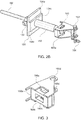
- Fig. 2A is an exploded view of components of the connection assembly 150 and Fig. 2B is a perspective view of components of the connection assembly 150 according to one or more aspects of the disclosure.
- the connection assembly 150 can include a wingnut 152, a counterplate 154, a sleeve 156, a bolt 158 (e.g., T-bolt), and a bolt block insert 160.
- the wingnut 152 can be any type of wingnut capable of engaging a threaded bolt 158, such as a T-Bolt with a DW20 Euro Thread.
- the wingnut can comprises any type of nut that can be threaded and unthreaded either by hand or using a tool.
- the counterplate 154 can be made of any material, including a metal such as aluminum, aluminum alloy, steel, steel alloy, or the like.
- the counterplate 154 has a first surface 154a (e.g., lower surface 154a) and a second surface 154b (e.g., raised surface 154b), with the raised surface 154b having a greater height with respect to front face 154c relative to the first (lower) surface 154a and the counterplate 154 having a greater thickness in the region of the raised surface 154b relative to the first surface 154a.
- the front face 154c of the counterplate 154 can have a substantially planar profile, defining a counterplate aperture 154d in the center thereof for receiving the sleeve 156.
- the raised surface 154b can have a substantially rectangular profile, also defining the counterplate aperture 154d in the center thereof.
- the first surfaces 154a can have planar profiles.
- the counterplate aperture 154d can define a plurality of inner diameters, with the raised surface having a larger diameter than a diameter corresponding to the first surface. This provides a stop from the sleeve advancing completely and freely through the aperture 154d.
- the wingnut 152 engages with the threading of the bolt 158 and is tightened snugly against a front face 154c of the counterplate 154.
- the bolt 158 passes through the sleeve 156 and through the counterplate 154 and engages with the bolt block plate 160a.
- the sleeve 156 engages with the counterplate aperture 154d.
- Fig. 3 is a view of a bolt block insert according to one or more aspects of the disclosure.
- the bolt block 160 (and any components thereof) can be made of any material, including a metal such as aluminum, aluminum alloy, steel, steel alloy, or the like.
- the bolt block insert 160 can include a bolt block plate 160a that defines a rectangular or substantially rectangular slot 160b.
- the substantially rectangular slot can include rounded or chamfered edges.
- the slot 160b can the T-shaped head 158a of the bolt 158.
- the bolt block insert 160 can also define a pair of pinholes 160d for receiving the pin 162.
- the cotter pin 164 can securely engage with the pin 162 and allow for engagement and disengagement with waler apertures 114a, b of the walers (e.g., walers 112a, 112b) of a formwork element 100a,b.
- the bolt block plate 160a defines at least one recess 160c (e.g., a pair of recesses 160c) for receiving the T-shaped head 158a of the bolt 158 once the T-shaped head passes through the slot 160b.
- the recesses 160c can have a rectangular or substantially rectangular two-dimensional profile.
- the substantially rectangular profile can include rounded or chamfered edges.
- the bolt block plate 160a can also include a planar or substantially planar face 160e. The face 160e can be substantially planar and while being partially defined by the slot 160b and the recesses 160c.
- Fig. 4 is a partial cross-sectional view along A-A of the formwork elements 100a, 100b of Fig. 1 with the connection assembly 150 according to one or more aspects of the disclosure.
- connection and disconnection of the formwork elements 100a, b via attachment and disengagement of the connection assembly 150 will described below with reference to Fig. 4 . While the attachment and disengagement are described below in a series of steps or processes, it should be understood that the steps need not necessarily be performed in the order presented below. That is to say, the order of steps can be modified, steps can be added, or steps can be omitted according to various implementations contemplated by the present application.
- a user can place formwork elements 100a and 100b adjacent to one another such that the steel face 110a of formwork element 100a is adjacent to side rail 106b of formwork element 100b.
- an aperture 110c defined by steel face 110a is in alignment with the side aperture 116b of the side rail 106b.
- the bolt block insert 160 can be inserted in a space between the walers 112b of formwork element 100b.
- a pin 162 can be inserted into the pinholes 160d of bolt block insert 160 and threaded through a waler aperture 114a, b, and a cotter pin 164 can be engaged with the pin 162 to allow for removable engagement of the bolt block insert 160 with the walers 112b of the formwork element 100b.
- a bearing 166 can be inserted in a pressure fit relationship between the bolt block insert 160 (and in particular bolt block plate 160a) and the side rail 106b.
- the bolt 158 can be inserted into and through the sleeve 156 and both can be inserted through the steel face 110a aperture 110c and the side aperture 116c until the reduced diameter portion 156a of sleeve 156 engages with a corresponding reduced diameter portion of bearing 166 and the T-shaped head 158a of the bolt 158 passes through the slot 160b defined by the bolt block plate 160a.
- the reduced diameter portion 156a can be a linearly reducing diameter or can be curved or can be curvilinear in profile.
- the bolt 158 can be rotated so that the T-shaped head engages with the recesses 160c rather than the planar face 160e.
- the counterplate 154 can then be advanced along the shaft of the bolt 158 such that the raised surface 154b is disposed between the walers 112b and the first surfaces 154a are flush against the front faces 112c.
- the wingnut 152 can then be threaded onto the shaft of the bolt 158 toward the counterplate 154 until it advances to the front face 154c of the counter plate 154. With the wingnut 152 snug against the front face 154c of the counterplate 154 and the T-shaped head 158a of the bolt secured firmly in the recesses 160c, the formwork elements 100a, b are securely engaged with one another.
- a user can first unthread the wingnut 152 along the thread of bolt 158 and away from the front face 154c of the counter plate 154.
- the wingnut can be unthreaded enough to allow the counterplate 154 to be advanced away from the walers 112 and allow the counterplate 154, and in particular the raised surface 154b, to rotate freely without interference from the walers 112b. In this position, the raised surfaces 154b are no longer disposed between the walers 112b.
- the counterplate 154 is then rotated such that the raised surfaces 154b engage with respective front faces 112c of the j-shaped walers 112b. This can be accomplished by rotating the counterplate 154 90°, 270°, or any rotational multiple thereof.
- the unthreading of the wingnut 152 allows for the bolt 158 to be rotated by 90 degrees, 270 degrees, or rotational multiples thereof to allow for the T-shaped head 158a to be advanced further into the slot 160b, rotated, and subsequently disengaged from the recesses 160c.
- the T-shaped head 158a of the bolt 158 can move freely in and/or out of the slot 160b.
- the wingnut 152 can be retightened to be snug against the front face 154c of the counterplate 154.
- the bolt 158, wingnut 152, counterplate 154 and sleeve 156 can be removed from the bolt block insert 160 and the formwork elements 110a,b.
- the elements 152, 154, 156, and 158 can be removed simultaneously as a singled unit. This advantageously provides additional leverage for the user and allows easier removal.
- the formwork elements 100a, b can be disengaged from one another.
- the bolt block insert 160 can also be removed from the formwork element 110b by removing the cotter pin 164, removing the pin 162 from the pinholes 160d of bolt block insert 160 and the waler aperture 114a,b, and removing the bolt block insert 160 and optionally the bearing 166 from the space between the walers 112b.
- the bolt block insert 160 is removable and replaceable in either of the formwork elements 100a 100b, which allows for greater flexibility of use of the formwork element on a construction site.
- a bolt block insert can be removed from a formwork element 100b and replaced with a bolt block insert of different specifications as required by the particular task on-site without the need to acquire an entire new formwork element.
Landscapes
- Engineering & Computer Science (AREA)
- Architecture (AREA)
- Mechanical Engineering (AREA)
- Civil Engineering (AREA)
- Structural Engineering (AREA)
- General Engineering & Computer Science (AREA)
- Forms Removed On Construction Sites Or Auxiliary Members Thereof (AREA)
Abstract
Description
- The present disclosure relates to connection assemblies for formwork.
- Certain formwork systems of the prior art use bolts to engage formwork elements with one another. During assembly and disassembly of the formwork system, the bolt may need to be removing or replaced depending on the circumstances. This can be a difficult process or can require the use of additional tools and thus be inconvenient. Such formwork systems may also have a fixed connection assembly that is specific to particular types of bolts. This can be inconvenient where various types of bolts are used on a site, thus requiring specific formwork assemblies to match.
- The present application overcomes the disadvantages of the prior art by providing a connection assembly reduces the difficulty in removing a bolt from a formwork system and provides a removable bolt block assembly for conveniently removing and replacing bolt block assemblies having different parameters without requirement the user of additional specific formwork assemblies.
- One or more aspects of the disclosure provide a connection assembly for connecting formwork elements, comprising: a counterplate comprising a plurality of surfaces having differing heights, the counterplate defining a counterplate aperture; a bolt block insert comprising a bolt block plate defining at least one recess; a bolt configured to pass through the counterplate aperture and removably engage with the at least one recess of the bolt block plate.
- In one example, the connection assembly further includes a wingnut that engages with a threaded shaft of the bolt.
- In one example, the connection assembly further includes a sleeve that surrounds a portion of the threaded shaft of the bolt.
- In one example, the plurality of surfaces having differing heights are configured to selectively engage with a front face of a waler of a formwork element.
- In one example, the plurality of surfaces having differing heights selectively engage with the front face of the waler based upon rotational position of the counterplate.
- In one example, the plurality of surfaces comprise a first surface having a first height and a second surface having a second height greater than the first height.
- In one example, the first surface engages with the front face of the waler when the formwork elements are securely engaged with one another.
- In one example, the second surface engages with the front face of the waler when the bolt is being removed from the bolt block insert.
- In one example, the bolt block insert is removably engagable with at least one of the formwork elements.
- In one example, the bolt block insert defines a pinhole for removably receiving a pin.
- In one example, the connection assembly further includes a cotter pin that engages with the pin.
- One or more aspects of the disclosure provide a formwork system, including: a first formwork element comprising a first waler; a second formwork element comprising a second waler, wherein at least one of the first waler and the second waler comprises a J-shaped profile; and a connection assembly configured to connect the first formwork element and the second formwork element, the connection assembly including: a counterplate comprising a plurality of surfaces having differing heights, the counterplate defining a counterplate aperture; a bolt block insert comprising a bolt block plate defining at least one recess; a bolt configured to pass through the counterplate aperture and removably engage with the at least one recess of the bolt block plate.
- In one example, the plurality of surfaces having differing heights are configured to selectively engage with a front face of at least one of the first waler or the second waler.
- In one example, the plurality of surfaces having differing heights selectively engage with the front face of the first waler or the second waler based upon rotational position of the counterplate.
- In one example, the plurality of surfaces comprise a first surface having a first height and a second surface having a second height greater than the first height.
- In one example, the first surface engages with the front face of the first waler or the second waler when the first formwork element and the second formwork element are securely engaged with one another.
- In one example, the second surface engages with the front face of the first waler or the second waler when the bolt is being removed from the bolt block insert.
- One or more aspects of the disclosure provide a method of disengaging a bolt from a formwork element, including: unthreading a nut with respect to the bolt; rotating a counterplate comprising a plurality of surfaces having differing heights such that at least one of the plurality of surfaces disengages with a waler of the formwork element and another of the plurality of surfaces engages with the waler of the formwork element; and threading the nut with respect to the bolt; and removing the counterplate and the bolt from the formwork element.
- In one example, the method further includes disengaging a T-shaped head of the bolt from a bolt block.
- In one example, the method further includes removing the bolt block from the formwork element.
- The invention description below refers to the accompanying drawings, of which:
-
Fig. 1 is a partial perspective view of a plurality of formwork elements connected via a connection assembly according to one or more aspects of the disclosure; -
Fig. 2A is an exploded view of components of the connection assembly; -
Fig. 2B is a perspective view of components of the connection assembly according to one or more aspects of the disclosure; -
Fig. 3 is a view of a bolt block insert according to one or more aspects of the disclosure; and -
Fig. 4 is a partial cross-sectional view along A-A of the formwork elements ofFig. 1 with the connection assembly according to one or more aspects of the disclosure. -
Fig. 1 is a partial perspective view of a plurality offormwork elements connection assembly 150 according to one or more aspects of the disclosure. - The
formwork element 100a can include atop rail 102a, abottom rail 104a that opposes and is parallel or substantially parallel to thetop rail 102a, afirst side rail 106a, and a second side rail (not shown) that opposes and is parallel or substantially parallel to thefirst side rail 106a. Theformwork element 100a can be of any size, shape or dimension in order to achieve the task of forming fresh concrete. For example, theformwork element 100a can be rectangular or substantially rectangular, with thetop rail 102a and thebottom rail 104a having equal length and thefirst side rail 106a and the second side rail (not shown) having equal length. - The
top rail 102a, thebottom rail 104a, and theside rail 106 a can be formed of any type of metal, such as steel, steel alloy, aluminum, aluminum alloy, or the like. Thefirst side rail 106a offormwork element 100a can define at least oneside aperture 116a for engaging with adjacent formwork elements. A second side rail (not shown) offormwork element 100a can also define an identical side aperture (not shown) that is opposed to theside aperture 116a. - The
formwork element 100a can be a wall formwork element, a column formwork element, or any other type of formwork element produced by PERI® Formwork Systems, Inc or PERI® GmbH. The formwork element can be formed of any type of material, including metals such as steel, steel alloy, aluminum, aluminum alloy or the like. In one example, the formwork element can have withstand a fresh concrete pressure of up to approximately 60 kN/m2. - The
formwork element 100a can include one ormore stiffeners 108a connected to asteel face 110a. The one ormore stiffeners 108a can be welded directly or indirectly to thesteel face 110a and can extend perpendicularly or substantially perpendicularly from a surface of thesteel face 110a. Thestiffeners 108a on thesteel face 110a can both be made of any type of metal, such as steel, steel alloy, aluminum, aluminum alloy, or the like. Theformwork element 110a can also include a pair ofwalers 112a. The walers can be formed of any type of metal such as aluminum, aluminum alloy, steel, steel alloy, or the like. Thewalers 112b can be an integrally-formed piece or can comprise a plurality of segments that are welded together to ultimately form the J-shaped profile. The walers can extend perpendicularly or substantially perpendicularly from the surface of thesteel face 110a and can be welded directly or indirectly to thesteel face 110a. - The
walers 112a can have a J-shaped profile (as shown inFig. 4 ) with the "hook" of the J-shape curving away from anopposed waler 112b. This shape allows for a worker to more easily establish a foothold within theformwork element 100a when the worker is climbing a series of formwork elements on a construction site. Further, the J-shaped profile allows for objects to be hung from the walers, such as walk access bracket(s), ladder(s), guy and brace connector(s), hold down bracket(s), strut connection(s), and other accessories. The J-shaped profile of thewalers 112a allows for a planar (or substantially planar) portion defined at least in part byfront face 112c. This shape defines an interior space between thewalers 112a defined at least in part by thewalers 112a, thesteel face 110a, and a plane that is coplanar with thefront faces 112c of therespective walers 112a. - The
walers 112a can also define a plurality ofwaler apertures 114a that can be used during connection offormwork elements 100a, b in conjunction with theconnection assembly 150, as will be described in greater detail below. While thewalers 112a are depicted with a J-shaped profile, it is contemplated that the walers can also have an L-shaped profile that provides a similarfront face 112c. - The
formwork element 100b that is connected withformwork element 100a can be the same type of formwork element asformwork element 100a and can have atop rail 102b, abottom rail 104b, afirst side rail 106b, a second side rail (not shown),steel face 110b,walers 112b,front faces 112d,waler apertures 114b, and one ormore side apertures 116b (shown inFig. 4 ). -
Fig. 2A is an exploded view of components of theconnection assembly 150 andFig. 2B is a perspective view of components of theconnection assembly 150 according to one or more aspects of the disclosure. - The
connection assembly 150 can include awingnut 152, acounterplate 154, asleeve 156, a bolt 158 (e.g., T-bolt), and abolt block insert 160. Thewingnut 152 can be any type of wingnut capable of engaging a threadedbolt 158, such as a T-Bolt with a DW20 Euro Thread. In other examples, the wingnut can comprises any type of nut that can be threaded and unthreaded either by hand or using a tool. - The
counterplate 154 can be made of any material, including a metal such as aluminum, aluminum alloy, steel, steel alloy, or the like. Thecounterplate 154 has afirst surface 154a (e.g.,lower surface 154a) and asecond surface 154b (e.g., raisedsurface 154b), with the raisedsurface 154b having a greater height with respect tofront face 154c relative to the first (lower)surface 154a and thecounterplate 154 having a greater thickness in the region of the raisedsurface 154b relative to thefirst surface 154a. - The
front face 154c of thecounterplate 154 can have a substantially planar profile, defining acounterplate aperture 154d in the center thereof for receiving thesleeve 156. The raisedsurface 154b can have a substantially rectangular profile, also defining thecounterplate aperture 154d in the center thereof. Thefirst surfaces 154a can have planar profiles. - The
counterplate aperture 154d can define a plurality of inner diameters, with the raised surface having a larger diameter than a diameter corresponding to the first surface. This provides a stop from the sleeve advancing completely and freely through theaperture 154d. - As shown in
Fig. 2B , thewingnut 152 engages with the threading of thebolt 158 and is tightened snugly against afront face 154c of thecounterplate 154. In this configuration, thebolt 158 passes through thesleeve 156 and through thecounterplate 154 and engages with thebolt block plate 160a. Thesleeve 156 engages with thecounterplate aperture 154d. -
Fig. 3 is a view of a bolt block insert according to one or more aspects of the disclosure. - The bolt block 160 (and any components thereof) can be made of any material, including a metal such as aluminum, aluminum alloy, steel, steel alloy, or the like. The
bolt block insert 160 can include abolt block plate 160a that defines a rectangular or substantiallyrectangular slot 160b. In this regard, the substantially rectangular slot can include rounded or chamfered edges. Theslot 160b can the T-shapedhead 158a of thebolt 158. Thebolt block insert 160 can also define a pair ofpinholes 160d for receiving thepin 162. Thecotter pin 164 can securely engage with thepin 162 and allow for engagement and disengagement with waler apertures 114a, b of the walers (e.g., walers 112a, 112b) of aformwork element 100a,b. - As shown in
Fig. 3 , thebolt block plate 160a defines at least onerecess 160c (e.g., a pair ofrecesses 160c) for receiving the T-shapedhead 158a of thebolt 158 once the T-shaped head passes through theslot 160b. In this regard, therecesses 160c can have a rectangular or substantially rectangular two-dimensional profile. In this regard, the substantially rectangular profile can include rounded or chamfered edges. Thebolt block plate 160a can also include a planar or substantiallyplanar face 160e. Theface 160e can be substantially planar and while being partially defined by theslot 160b and therecesses 160c. -
Fig. 4 is a partial cross-sectional view along A-A of theformwork elements Fig. 1 with theconnection assembly 150 according to one or more aspects of the disclosure. - Connection and disconnection of the
formwork elements 100a, b via attachment and disengagement of theconnection assembly 150 will described below with reference toFig. 4 . While the attachment and disengagement are described below in a series of steps or processes, it should be understood that the steps need not necessarily be performed in the order presented below. That is to say, the order of steps can be modified, steps can be added, or steps can be omitted according to various implementations contemplated by the present application. - A user can place
formwork elements steel face 110a offormwork element 100a is adjacent toside rail 106b offormwork element 100b. In this arrangement, anaperture 110c defined bysteel face 110a is in alignment with theside aperture 116b of theside rail 106b. Thebolt block insert 160 can be inserted in a space between the walers 112b offormwork element 100b. Apin 162 can be inserted into thepinholes 160d ofbolt block insert 160 and threaded through awaler aperture 114a, b, and acotter pin 164 can be engaged with thepin 162 to allow for removable engagement of thebolt block insert 160 with the walers 112b of theformwork element 100b. During engagement of thebolt block insert 160, abearing 166 can be inserted in a pressure fit relationship between the bolt block insert 160 (and in particularbolt block plate 160a) and theside rail 106b. - The
bolt 158 can be inserted into and through thesleeve 156 and both can be inserted through thesteel 110c and the side aperture 116c until the reducedface 110a aperturediameter portion 156a ofsleeve 156 engages with a corresponding reduced diameter portion of bearing 166 and the T-shapedhead 158a of thebolt 158 passes through theslot 160b defined by thebolt block plate 160a. The reduceddiameter portion 156a can be a linearly reducing diameter or can be curved or can be curvilinear in profile. Thebolt 158 can be rotated so that the T-shaped head engages with therecesses 160c rather than theplanar face 160e. - The
counterplate 154 can then be advanced along the shaft of thebolt 158 such that the raisedsurface 154b is disposed between the walers 112b and thefirst surfaces 154a are flush against the front faces 112c. Thewingnut 152 can then be threaded onto the shaft of thebolt 158 toward thecounterplate 154 until it advances to thefront face 154c of thecounter plate 154. With thewingnut 152 snug against thefront face 154c of thecounterplate 154 and the T-shapedhead 158a of the bolt secured firmly in therecesses 160c, theformwork elements 100a, b are securely engaged with one another. - To remove the
bolt 158, a user can first unthread thewingnut 152 along the thread ofbolt 158 and away from thefront face 154c of thecounter plate 154. The wingnut can be unthreaded enough to allow thecounterplate 154 to be advanced away from the walers 112 and allow thecounterplate 154, and in particular the raisedsurface 154b, to rotate freely without interference from thewalers 112b. In this position, the raisedsurfaces 154b are no longer disposed between the walers 112b. Thecounterplate 154 is then rotated such that the raisedsurfaces 154b engage with respective front faces 112c of the j-shapedwalers 112b. This can be accomplished by rotating thecounterplate 154 90°, 270°, or any rotational multiple thereof. In this way, the unthreading of thewingnut 152 allows for thebolt 158 to be rotated by 90 degrees, 270 degrees, or rotational multiples thereof to allow for the T-shapedhead 158a to be advanced further into theslot 160b, rotated, and subsequently disengaged from therecesses 160c. In this alignment, the T-shapedhead 158a of thebolt 158 can move freely in and/or out of theslot 160b. - Once aligned, the
wingnut 152 can be retightened to be snug against thefront face 154c of thecounterplate 154. Once retightened, thebolt 158,wingnut 152,counterplate 154 andsleeve 156 can be removed from thebolt block insert 160 and theformwork elements 110a,b. In this regard, theelements formwork elements 100a, b can be disengaged from one another. - The
bolt block insert 160 can also be removed from theformwork element 110b by removing thecotter pin 164, removing thepin 162 from thepinholes 160d ofbolt block insert 160 and thewaler aperture 114a,b, and removing thebolt block insert 160 and optionally the bearing 166 from the space between the walers 112b. In this regard, thebolt block insert 160 is removable and replaceable in either of theformwork elements 100a 100b, which allows for greater flexibility of use of the formwork element on a construction site. For example, a bolt block insert can be removed from aformwork element 100b and replaced with a bolt block insert of different specifications as required by the particular task on-site without the need to acquire an entire new formwork element. - The foregoing has been a detailed description of illustrative embodiments of the invention. Various modifications and additions can be made without departing from the spirit and scope of this invention. Features of each of the various embodiments described above may be combined with features of other described embodiments as appropriate in order to provide a multiplicity of feature combinations in associated new embodiments. Furthermore, while the foregoing describes a number of separate embodiments of the apparatus and method of the present invention, what has been described herein is merely illustrative of the application of the principles of the present invention. Accordingly, this description is meant to be taken only by way of example, and not to otherwise limit the scope of this invention.
Claims (15)
- A connection assembly for connecting formwork elements, comprising:a counterplate comprising a plurality of surfaces having differing heights, the counterplate defining a counterplate aperture;a bolt block insert comprising a bolt block plate defining at least one recess;a bolt configured to pass through the counterplate aperture and removably engage with the at least one recess of the bolt block plate.
- The connection assembly of claim 1, further comprising a wingnut that engages with a threaded shaft of the bolt, wherein in particular the connection assembly further comprises a sleeve that surrounds a portion of the threaded shaft of the bolt.
- The connection assembly of claim 1, wherein the plurality of surfaces having differing heights are configured to selectively engage with a front face of a waler of a formwork element.
- The connection assembly of claim 3, wherein the plurality of surfaces having differing heights either selectively engage with the front face of the waler based upon rotational position of the counterplate or comprise a first surface having a first height and a second surface having a second height greater than the first height.
- The connection assembly of claim 4, wherein the first surface engages with the front face of the waler when the formwork elements are securely engaged with one another, wherein in particular the second surface engages with the front face of the waler when the bolt is being removed from the bolt block insert.
- The connection assembly of claim 1, wherein the bolt block insert is removably engagable with at least one of the formwork elements.
- The connection assembly of claim 6, wherein the bolt block insert defines a pinhole for removably receiving a pin, wherein in particular the connection assembly further comprises a cotter pin that engages with the pin.
- A formwork system, comprising:a first formwork element comprising a first waler;a second formwork element comprising a second waler, wherein at least one of the first waler and the second waler comprises a J-shaped profile; anda connection assembly configured to connect the first formwork element and the second formwork element, the connection assembly comprising:a counterplate comprising a plurality of surfaces having differing heights, the counterplate defining a counterplate aperture;a bolt block insert comprising a bolt block plate defining at least one recess;a bolt configured to pass through the counterplate aperture and removably engage with the at least one recess of the bolt block plate.
- The formwork system of claim 8, wherein the plurality of surfaces having differing heights are configured to selectively engage with a front face of at least one of the first waler or the second waler.
- The formwork system of claim 9, wherein the plurality of surfaces having differing heights selectively engage with the front face of the first waler or the second waler based upon rotational position of the counterplate.
- The formwork system of claim 10, wherein the plurality of surfaces comprise a first surface having a first height and a second surface having a second height greater than the first height.
- The formwork system of claim 11, wherein the first surface engages with the front face of the first waler or the second waler when the first formwork element and the second formwork element are securely engaged with one another.
- The formwork system of claim 12, wherein the second surface engages with the front face of the first waler or the second waler when the bolt is being removed from the bolt block insert.
- A method of disengaging a bolt from a formwork element, comprising:unthreading a nut with respect to the bolt;rotating a counterplate comprising a plurality of surfaces having differing heights such that at least one of the plurality of surfaces disengages with a waler of the formwork element and another of the plurality of surfaces engages with the waler of the formwork element;threading the nut with respect to the bolt; andremoving the counterplate and the bolt from the formwork element.
- The method of claim 14, further comprising disengaging a T-shaped head of the bolt from a bolt block, wherein in particular the method further comprises removing the bolt block from the formwork element.
Applications Claiming Priority (1)
| Application Number | Priority Date | Filing Date | Title |
|---|---|---|---|
| US16/160,898 US10975585B2 (en) | 2018-10-15 | 2018-10-15 | Connection assembly for formwork |
Publications (2)
| Publication Number | Publication Date |
|---|---|
| EP3640411A1 true EP3640411A1 (en) | 2020-04-22 |
| EP3640411B1 EP3640411B1 (en) | 2023-12-20 |
Family
ID=68281031
Family Applications (1)
| Application Number | Title | Priority Date | Filing Date |
|---|---|---|---|
| EP19203244.9A Active EP3640411B1 (en) | 2018-10-15 | 2019-10-15 | Connection assembly for formwork |
Country Status (4)
| Country | Link |
|---|---|
| US (1) | US10975585B2 (en) |
| EP (1) | EP3640411B1 (en) |
| CA (1) | CA3058752C (en) |
| MY (1) | MY200643A (en) |
Families Citing this family (2)
| Publication number | Priority date | Publication date | Assignee | Title |
|---|---|---|---|---|
| CN213359167U (en) * | 2020-09-08 | 2021-06-04 | 青岛长淮机械有限公司 | Adjusting part and glass clamp |
| CN113250444A (en) * | 2021-06-02 | 2021-08-13 | 晟通科技集团有限公司 | Connecting fastener and support frame |
Citations (5)
| Publication number | Priority date | Publication date | Assignee | Title |
|---|---|---|---|---|
| GB2091332A (en) * | 1981-01-15 | 1982-07-28 | Harsco Corp | Tie rod connector plate |
| BE905030A (en) * | 1986-07-02 | 1986-11-03 | Cometal Nv | Concrete formwork coupling piece - has two parts with positioning devices engaging together in different settings |
| GB2179697A (en) * | 1985-08-16 | 1987-03-11 | Rapid Metal Developments Ltd | Formwork support system and clamp device for use therein |
| US5137250A (en) * | 1990-01-05 | 1992-08-11 | Economy Forms Corporation | Tie rod bearing unit for use in concrete form assemblies |
| EP1887163A2 (en) * | 2006-08-07 | 2008-02-13 | All Bast, Naamloze vennootschap | Coupling-device for panel shuttering |
Family Cites Families (104)
| Publication number | Priority date | Publication date | Assignee | Title |
|---|---|---|---|---|
| US1779908A (en) * | 1929-06-07 | 1930-10-28 | Graziano Nicholas | Wall mold |
| ES237075A1 (en) | 1956-09-11 | 1958-02-01 | Siemens Ag | Procedure to introduce thermal contactors in the rolling of appliances or electrical machines (Machine-translation by Google Translate, not legally binding) |
| US3795393A (en) | 1971-12-03 | 1974-03-05 | S Melfi | Concrete form and clamp therefore |
| US3899152A (en) | 1971-12-12 | 1975-08-12 | Aluma Building Syst Inc | Concrete form including extruded aluminum support structure |
| US3945601A (en) | 1973-03-23 | 1976-03-23 | Rowley Edward C | Knock-down reusable column form |
| US4044987A (en) * | 1975-11-06 | 1977-08-30 | Dusan Tausanovitch | Externally controlled spreader system |
| US4033544A (en) | 1976-06-03 | 1977-07-05 | Aluma Building Systems Incorporated | Wall forming structure for poured concrete walls |
| DE2635565A1 (en) | 1976-08-06 | 1978-02-09 | Marijan Dipl Ing Kresic | Reinforced concrete building skeleton frame formwork - has constant grid ceiling rectangular and triangular panel segments and intervening screens |
| ES457186A1 (en) | 1977-03-16 | 1978-03-01 | Encofrados J Alsina Sa | FORMWORK SYSTEM FOR FLOOR FORGES. |
| US4144690A (en) | 1977-12-19 | 1979-03-20 | Aluma Building Systems Incorporated | Concrete forming structures |
| ES471247A1 (en) | 1978-06-29 | 1979-01-16 | Encofrados J Alsina Sa | System of formwork for forged jacques, floors and similar (Machine-translation by Google Translate, not legally binding) |
| EP0048624A3 (en) | 1980-09-24 | 1982-09-29 | Aluma Systems Incorporated | Lightweight, welded aluminium shoring frame |
| EP0049096B1 (en) | 1980-09-29 | 1985-12-27 | Aluma Systems Incorporated | Bolted aluminium shoring frame |
| CA1159274A (en) | 1981-03-27 | 1983-12-27 | Ronald J. Johnston | Concrete forming structures |
| CA1242591A (en) | 1984-12-27 | 1988-10-04 | Ronald J. Johnston | Truss arrangement |
| JP2657390B2 (en) | 1988-04-30 | 1997-09-24 | 東急建設株式会社 | Construction method of inclined concrete structure |
| US4930937A (en) | 1988-07-26 | 1990-06-05 | Symons Corporation | Box culvert traveler for use with concrete forming systems |
| US4976401A (en) | 1989-02-07 | 1990-12-11 | Western Forms, Inc. | Adjustable corner squaring strip for a concrete column form |
| GB2229419A (en) | 1989-03-21 | 1990-09-26 | Aluma Systems | Jacks for building supports. |
| JP2920308B2 (en) | 1990-04-04 | 1999-07-19 | 鹿島建設株式会社 | Formwork method and formwork equipment |
| JPH03295979A (en) | 1990-04-16 | 1991-12-26 | Nikkei Aruma Syst Kk | Frame and construction method using frame thereof |
| US5240089A (en) * | 1991-07-17 | 1993-08-31 | Speral Aluminum Inc. | Modular scaffolding assembly |
| US5263296A (en) * | 1991-07-17 | 1993-11-23 | Speral Aluminium Inc. | Modular scaffolding assembly |
| JP2975211B2 (en) * | 1992-03-17 | 1999-11-10 | 慶文 松村 | Concrete formwork |
| CA2110342C (en) | 1993-11-30 | 1998-02-10 | Clarence Pangsum Au | Wall form support system |
| DE4417466A1 (en) | 1994-04-15 | 1995-10-19 | Asmussen Karl Heinz | Shuttering for concrete casting |
| US5644889A (en) | 1994-08-05 | 1997-07-08 | Dur-O-Wal, Inc. | Remedial wall anchor system |
| CA2141463C (en) | 1995-01-31 | 2006-08-01 | Clarence Pangsum Au | Modular concrete wallform |
| US6223482B1 (en) * | 1995-08-17 | 2001-05-01 | Herman Zohar | Portable, easily composable supporting skeleton |
| CA2178031A1 (en) | 1996-06-03 | 1997-12-04 | Peter John Rogers | Wallform panel with modified side rails |
| CA2179084C (en) | 1996-06-13 | 2008-04-15 | Paul James Hannigan | Captured clamp for wallform panel |
| US5927038A (en) * | 1996-07-22 | 1999-07-27 | Goldberg; William S. | Expandable self-locking frame |
| US5816562A (en) | 1996-10-11 | 1998-10-06 | Symons Corporation | Sand jack apparatus |
| ATE269468T1 (en) | 1997-04-04 | 2004-07-15 | Encofrados J Alsina Sa | FORMWORK SUPPORT |
| CA2205154C (en) | 1997-05-16 | 2002-07-02 | Aluma Enterprises Inc. | Integrated frame and post support system |
| CA2206191C (en) | 1997-05-27 | 2007-08-07 | Aluma Enterprises Inc. | Wallform panel and side rail |
| DE19758276A1 (en) | 1997-12-31 | 1999-07-01 | Dingler Gerhard | Device for concrete shuttering |
| FR2780743B1 (en) | 1998-07-01 | 2003-08-08 | Emmanuel Antoine Leonce Terron | FORMWORK FOR REALIZING REINFORCED CONCRETE PILLARS |
| ES1042559Y (en) | 1999-04-13 | 2000-02-01 | Encofrados J Alsina Sa | FORMWORK FOR PILLARS. |
| US6715729B2 (en) | 2000-02-18 | 2004-04-06 | Symons Corporation | Overhanging form system and method of using the same |
| US6676102B1 (en) | 2000-02-18 | 2004-01-13 | Symons Corporation | Adjustable modular form system and method for rectilinear concrete column form |
| RU15745U1 (en) | 2000-05-26 | 2000-11-10 | Блохин Валерий Евгеньевич | COLUMN FORMWORK FORMWORK |
| US6502802B2 (en) | 2001-02-23 | 2003-01-07 | Wilian Holding Company | Double bias corner form |
| US20020158184A1 (en) | 2001-02-23 | 2002-10-31 | Mccracken Robert | Concrete form using face sheet as tension flange for stiffeners |
| US6581898B2 (en) | 2001-02-23 | 2003-06-24 | Wilian Holding Company | Bearing block for alignment and handling of concrete forms |
| DE10114161A1 (en) | 2001-03-22 | 2002-09-26 | Thyssen Huennebeck Gmbh | Shell element used for constructing concrete building components comprises a plate-like support covered on one side with a foil removably fixed to the support by a heat-deactivatable adhesive |
| ES1049094Y (en) | 2001-04-27 | 2002-03-16 | Encofrados J Alsina Sa | DEVICE FOR THE FORMATION OF CHAFLANES IN ENCOFRADOS. |
| ES2178604B1 (en) | 2001-04-27 | 2004-10-01 | Encofrados J. Alsina, S.A. | CURVED FORMWORK. |
| ES1049093Y (en) | 2001-04-27 | 2002-03-16 | Encofrados J Alsina Sa | AMOVIBLE HANDLE FOR CONCRETE CONCRETE |
| ES1049092Y (en) | 2001-04-27 | 2002-03-16 | Encofrados J Alsina Sa | ALIGNMENT DEVICE FOR CONCRETE CONCRETE. |
| ES2178610B1 (en) | 2001-06-04 | 2004-09-01 | Encofrados J. Alsina, S.A. | SAFETY DEVICE FOR WORK ON HORIZONTAL SURFACES IN CONSTRUCTION WORKS. |
| ES1049390Y (en) | 2001-06-13 | 2002-04-16 | Encofrados J Alsina Sa | ANCHORING DEVICE FOR CONCRETE CONCRETE. |
| US20020189175A1 (en) | 2001-06-15 | 2002-12-19 | Lancelot Harry B. | End anchors |
| ES1049674Y (en) | 2001-06-20 | 2002-05-16 | Encofrados J Alsina Sa | SUPPLEMENTARY ELEMENT FOR PLACEMENT PLATES. |
| ITRM20010377A1 (en) | 2001-07-02 | 2003-01-02 | Caluisi Anna | REMAINING STRUCTURAL FORMWORKS FOR REINFORCED AND NON-REINFORCED CONCRETE CASTINGS. |
| CA2372358C (en) | 2002-02-20 | 2006-05-09 | Aluma Enterprises Inc. | Column hung truss system |
| DE60308488D1 (en) | 2002-02-20 | 2006-11-02 | Aluma Entpr Inc | ON THE SUPPORT HANGING FACHWERKSYSTEM |
| US20030208969A1 (en) | 2002-05-10 | 2003-11-13 | Dayton Superior Corporation | Lift anchor for concrete panel |
| ES2229899B1 (en) | 2003-05-19 | 2006-02-16 | Ingenieria De Encofrados Y Servicios, S.L. | DEVICE FOR THE FORMATION OF CHAFLANES IN PILLARS OF ARMED CONCRETE. |
| ES1056678Y (en) | 2004-02-09 | 2004-08-01 | Encofrados J Alsina Sa | SECURITY DEVICE FOR CONSTRUCTION WORKS. |
| ES1054856Y (en) | 2003-05-26 | 2003-12-16 | Encofrados J Alsina Sa | SAFETY DEVICE FOR WORK IN CONSTRUCTION WORKS |
| ES1055827Y (en) | 2003-10-28 | 2004-05-01 | Encofrados J Alsina Sa | POINT WITH SAFETY DEVICE. |
| ES2231036B1 (en) | 2003-10-31 | 2006-07-01 | Encofrados J. Alsina, S.A. | STRUT. |
| CN100447363C (en) | 2003-11-13 | 2008-12-31 | 古斯塔沃·塞拉诺罗德里格斯 | Metal mould with accessories for casting concrete |
| ES2265211B1 (en) | 2004-02-09 | 2008-01-01 | Encofrados J. Alsina, S.A. | HOOK FOR FORMWORK. |
| ES2275374B1 (en) | 2004-06-10 | 2008-05-01 | Encofrados J. Alsina, S.A. | SECURITY DEVICE APPLICABLE TO STRUCTURES USED FOR CONSTRUCTION HELP. |
| US8042786B2 (en) | 2004-06-18 | 2011-10-25 | Dayton Superior Corporation | Locking system having mounting block with mounting arm and slide member for securing concrete form panels |
| ES2294874B1 (en) | 2004-09-20 | 2009-02-01 | Encofrados J. Alsina, S.A. | DEVICE TO FACILITATE THE DOWNLOAD OF SUPPORT ELEMENTS, SUCH AS POINTS OR CIMBRAS. |
| JP4361049B2 (en) | 2004-12-06 | 2009-11-11 | コリア ナショナル ハウジング コーポレーション | Assembled box-type steel pipe column for filling concrete and method for producing the same |
| ES2274699B1 (en) | 2005-07-06 | 2008-05-01 | Encofrados J. Alsina, S.A. | SECURITY SYSTEM FOR WORK ON SURFACES IN CONSTRUCTION WORKS. |
| US20070101666A1 (en) * | 2005-10-21 | 2007-05-10 | Munch James A | Corrugated plastic storm shutter system |
| FR2897376B1 (en) | 2006-02-13 | 2008-05-16 | Mesa Imalat Sanayii Ve Ticaret | IMPROVED FORMWORK SYSTEM FOR BUILDING OR PUBLIC WORKS. |
| ES2303434B1 (en) | 2006-03-28 | 2009-06-03 | Inveral, S.A. | PROCEDURE FOR THE MANUFACTURE OF A UNION DEVICE FOR COOLED PANELS AND DEVICE OBTAINED ACCORDING TO SUCH PROCEDURE. |
| US7387470B2 (en) | 2006-05-12 | 2008-06-17 | Mccracken Robert | Stackable concrete forming apparatus components |
| CA2549260C (en) | 2006-06-01 | 2013-12-03 | Aluma Systems Inc. | Toeboard clamp system |
| US7938380B2 (en) | 2007-02-28 | 2011-05-10 | Brand Services, Llc | Column hung overhang bracket for concrete forming systems |
| ES2284414B1 (en) | 2007-05-11 | 2008-06-16 | Sistemas Tecnicos De Encofrados, S.A. | "PANEL FOR THE WALLING OF WALLS AND PILLARS". |
| US20090084930A1 (en) | 2007-09-28 | 2009-04-02 | Sonoco Development, Inc. | Concrete form for pouring polygonal columns |
| JP4164117B1 (en) | 2008-01-26 | 2008-10-08 | 株式会社高長建設 | Formwork apparatus for prismatic concrete structure and construction method of prismatic concrete structure using the same |
| ES2349602B1 (en) | 2008-10-01 | 2011-11-21 | Inveral, S.A. | VIGA PORTA - SOPANDAS FOR THE WRAPPING OF FORGED |
| WO2010074550A1 (en) | 2008-12-23 | 2010-07-01 | Nan San Lee | Assemblage formwork |
| CA2668598C (en) | 2009-06-11 | 2012-05-15 | Aluma Systems Inc. | Concrete forming panel |
| KR101035423B1 (en) | 2009-06-25 | 2011-05-20 | (주)블루폼 | Reinforcement beam for formwork and system panel using the same |
| CO6290099A1 (en) * | 2009-12-10 | 2011-06-20 | Pimiento Efrain Rojas | GRADUABLE METALLIC FORMWORK SYSTEM FOR CONCRETE STRUCTURES |
| CA135247S (en) | 2010-04-29 | 2010-12-16 | Abzac Canada Inc | Formwork |
| CN202441052U (en) | 2012-03-01 | 2012-09-19 | 青岛两仪环保工程有限公司 | Column mould system |
| US9611663B2 (en) | 2012-06-13 | 2017-04-04 | Norton Baum | Self-lifting concrete form adapted to accommodate horizontal reinforcing steel |
| US20140008511A1 (en) | 2012-07-06 | 2014-01-09 | Inveral, S.A. | Fall protection device |
| DE102012212607A1 (en) * | 2012-07-18 | 2014-02-06 | Harsco Infrastructure Services Gmbh | Fastenable anchor system of a wall formwork and method |
| DE102012217689A1 (en) | 2012-09-28 | 2014-04-03 | Harsco Infrastructure Services Gmbh | Wall formwork and wall formwork system |
| DE102012217688A1 (en) | 2012-09-28 | 2014-04-03 | Harsco Infrastructure Services Gmbh | Wall formwork with optional anchor point |
| DE102012217827A1 (en) | 2012-09-28 | 2014-04-03 | Harsco Infrastructure Services Gmbh | Chalkboard with corner recess and component |
| CN102877643B (en) | 2012-10-19 | 2015-07-15 | 天津住宅集团建设工程总承包有限公司 | Pillar plastic formwork construction method for buildings |
| CN104675108A (en) | 2013-12-03 | 2015-06-03 | 黑龙江融德建筑技术开发有限公司 | Column formwork structural design |
| ES1105580Y (en) | 2014-03-25 | 2014-07-01 | Encofrados J Alsina Sa | SQUARE FOR FIXING ELEMENTS OF FORMWORK |
| ES1117930Y (en) | 2014-05-09 | 2014-10-20 | Encofrados J Alsina Sa | DEVICE FOR FIXING AND SECURING MODULAR FORMWORK STRUCTURES |
| ES2561907B1 (en) | 2014-08-27 | 2016-12-07 | Encofrados J. Alsina, S.A. | Leveling accessory to maintain the level of a horizontal formwork panel and formwork system comprising it |
| PH22014000755U3 (en) | 2014-12-19 | 2015-07-10 | Encofrados J Alsina Sa | Supporting girder for floor slab formwork |
| WO2016139513A1 (en) | 2015-03-05 | 2016-09-09 | Andamios Y Encofrados S.A.S. | Universal modular panel for formwork systems for the construction of pillars or columns |
| ES2594344B1 (en) | 2015-06-16 | 2017-09-26 | Encofrados J. Alsina, S.A. | Device for fixing and securing a formwork structure |
| ITUB20155637A1 (en) | 2015-11-17 | 2017-05-17 | Faresin Building S P A | PERFECT CASSERATURE STRUCTURE |
| CN106907002A (en) | 2017-03-28 | 2017-06-30 | 中铁建设集团有限公司 | A kind of adjustable shaped steel fixed system |
| CN206903213U (en) | 2017-07-11 | 2018-01-19 | 青岛恒生源集团建设有限公司 | A kind of pillar structure for being easy to filling concrete and adjustable height |
| US10920433B2 (en) | 2018-06-13 | 2021-02-16 | Wilian Holding Co. | Heavy duty spanning forms and related systems and methods |
-
2018
- 2018-10-15 US US16/160,898 patent/US10975585B2/en not_active Expired - Fee Related
-
2019
- 2019-10-14 MY MYPI2019006082A patent/MY200643A/en unknown
- 2019-10-15 CA CA3058752A patent/CA3058752C/en active Active
- 2019-10-15 EP EP19203244.9A patent/EP3640411B1/en active Active
Patent Citations (5)
| Publication number | Priority date | Publication date | Assignee | Title |
|---|---|---|---|---|
| GB2091332A (en) * | 1981-01-15 | 1982-07-28 | Harsco Corp | Tie rod connector plate |
| GB2179697A (en) * | 1985-08-16 | 1987-03-11 | Rapid Metal Developments Ltd | Formwork support system and clamp device for use therein |
| BE905030A (en) * | 1986-07-02 | 1986-11-03 | Cometal Nv | Concrete formwork coupling piece - has two parts with positioning devices engaging together in different settings |
| US5137250A (en) * | 1990-01-05 | 1992-08-11 | Economy Forms Corporation | Tie rod bearing unit for use in concrete form assemblies |
| EP1887163A2 (en) * | 2006-08-07 | 2008-02-13 | All Bast, Naamloze vennootschap | Coupling-device for panel shuttering |
Also Published As
| Publication number | Publication date |
|---|---|
| US20200115913A1 (en) | 2020-04-16 |
| CA3058752A1 (en) | 2020-04-15 |
| CA3058752C (en) | 2022-05-03 |
| MY200643A (en) | 2024-01-08 |
| US10975585B2 (en) | 2021-04-13 |
| EP3640411B1 (en) | 2023-12-20 |
Similar Documents
| Publication | Publication Date | Title |
|---|---|---|
| US12595657B2 (en) | Formwork panel of a formwork system | |
| US7152843B2 (en) | Gripping ribs fastening system for concrete forming panels | |
| US20080173788A1 (en) | Lightweight Crane-Set Forming Panel | |
| US9068363B2 (en) | Adjustable metal formwork system for concrete structures | |
| EP3640411B1 (en) | Connection assembly for formwork | |
| US12195961B2 (en) | Formwork system | |
| US9435128B2 (en) | Overlap arrangement of at least two decking planks | |
| JP2013076315A (en) | Wedge framed clamp | |
| WO2001061126A9 (en) | Overhanging form system and method of using the same | |
| US5388666A (en) | Support scaffold | |
| WO2003058008A1 (en) | Method and apparatus for forming construction panels and structures | |
| KR100905506B1 (en) | Hull Block Clamp | |
| KR100924522B1 (en) | Hull Block Clamp | |
| GB2539371A (en) | Railway shuttering apparatus | |
| CN104912333A (en) | Wall construction system and construction method | |
| US10137454B2 (en) | Maintenance platform of jaw crusher | |
| JP6695591B2 (en) | Wrench tool | |
| US20190264454A1 (en) | Concrete Form Lock | |
| KR200439786Y1 (en) | Hull Block Clamp | |
| US12024905B2 (en) | Concrete form construction apparatus and system | |
| EP3875706A1 (en) | Scaffolding | |
| KR101498956B1 (en) | Scaffolding clamp | |
| JP3066281B2 (en) | Hydraulic jack connection method and connection device | |
| KR930006808Y1 (en) | Connection of concrete formwork | |
| NL2008545C2 (en) | DEVICE FOR ANCHORING A BUILDING SCAFFOLDING. |
Legal Events
| Date | Code | Title | Description |
|---|---|---|---|
| PUAI | Public reference made under article 153(3) epc to a published international application that has entered the european phase |
Free format text: ORIGINAL CODE: 0009012 |
|
| STAA | Information on the status of an ep patent application or granted ep patent |
Free format text: STATUS: THE APPLICATION HAS BEEN PUBLISHED |
|
| AK | Designated contracting states |
Kind code of ref document: A1 Designated state(s): AL AT BE BG CH CY CZ DE DK EE ES FI FR GB GR HR HU IE IS IT LI LT LU LV MC MK MT NL NO PL PT RO RS SE SI SK SM TR |
|
| AX | Request for extension of the european patent |
Extension state: BA ME |
|
| STAA | Information on the status of an ep patent application or granted ep patent |
Free format text: STATUS: REQUEST FOR EXAMINATION WAS MADE |
|
| STAA | Information on the status of an ep patent application or granted ep patent |
Free format text: STATUS: EXAMINATION IS IN PROGRESS |
|
| 17P | Request for examination filed |
Effective date: 20201022 |
|
| RBV | Designated contracting states (corrected) |
Designated state(s): AL AT BE BG CH CY CZ DE DK EE ES FI FR GB GR HR HU IE IS IT LI LT LU LV MC MK MT NL NO PL PT RO RS SE SI SK SM TR |
|
| 17Q | First examination report despatched |
Effective date: 20201130 |
|
| GRAP | Despatch of communication of intention to grant a patent |
Free format text: ORIGINAL CODE: EPIDOSNIGR1 |
|
| STAA | Information on the status of an ep patent application or granted ep patent |
Free format text: STATUS: GRANT OF PATENT IS INTENDED |
|
| INTG | Intention to grant announced |
Effective date: 20230714 |
|
| GRAS | Grant fee paid |
Free format text: ORIGINAL CODE: EPIDOSNIGR3 |
|
| GRAA | (expected) grant |
Free format text: ORIGINAL CODE: 0009210 |
|
| STAA | Information on the status of an ep patent application or granted ep patent |
Free format text: STATUS: THE PATENT HAS BEEN GRANTED |
|
| RAP3 | Party data changed (applicant data changed or rights of an application transferred) |
Owner name: PERI SE |
|
| AK | Designated contracting states |
Kind code of ref document: B1 Designated state(s): AL AT BE BG CH CY CZ DE DK EE ES FI FR GB GR HR HU IE IS IT LI LT LU LV MC MK MT NL NO PL PT RO RS SE SI SK SM TR |
|
| REG | Reference to a national code |
Ref country code: GB Ref legal event code: FG4D |
|
| REG | Reference to a national code |
Ref country code: CH Ref legal event code: EP |
|
| REG | Reference to a national code |
Ref country code: DE Ref legal event code: R096 Ref document number: 602019043506 Country of ref document: DE |
|
| REG | Reference to a national code |
Ref country code: IE Ref legal event code: FG4D |
|
| P01 | Opt-out of the competence of the unified patent court (upc) registered |
Effective date: 20231229 |
|
| PG25 | Lapsed in a contracting state [announced via postgrant information from national office to epo] |
Ref country code: GR Free format text: LAPSE BECAUSE OF FAILURE TO SUBMIT A TRANSLATION OF THE DESCRIPTION OR TO PAY THE FEE WITHIN THE PRESCRIBED TIME-LIMIT Effective date: 20240321 |
|
| REG | Reference to a national code |
Ref country code: LT Ref legal event code: MG9D |
|
| PG25 | Lapsed in a contracting state [announced via postgrant information from national office to epo] |
Ref country code: LT Free format text: LAPSE BECAUSE OF FAILURE TO SUBMIT A TRANSLATION OF THE DESCRIPTION OR TO PAY THE FEE WITHIN THE PRESCRIBED TIME-LIMIT Effective date: 20231220 |
|
| REG | Reference to a national code |
Ref country code: NL Ref legal event code: MP Effective date: 20231220 |
|
| PG25 | Lapsed in a contracting state [announced via postgrant information from national office to epo] |
Ref country code: ES Free format text: LAPSE BECAUSE OF FAILURE TO SUBMIT A TRANSLATION OF THE DESCRIPTION OR TO PAY THE FEE WITHIN THE PRESCRIBED TIME-LIMIT Effective date: 20231220 |
|
| PG25 | Lapsed in a contracting state [announced via postgrant information from national office to epo] |
Ref country code: LT Free format text: LAPSE BECAUSE OF FAILURE TO SUBMIT A TRANSLATION OF THE DESCRIPTION OR TO PAY THE FEE WITHIN THE PRESCRIBED TIME-LIMIT Effective date: 20231220 Ref country code: GR Free format text: LAPSE BECAUSE OF FAILURE TO SUBMIT A TRANSLATION OF THE DESCRIPTION OR TO PAY THE FEE WITHIN THE PRESCRIBED TIME-LIMIT Effective date: 20240321 Ref country code: FI Free format text: LAPSE BECAUSE OF FAILURE TO SUBMIT A TRANSLATION OF THE DESCRIPTION OR TO PAY THE FEE WITHIN THE PRESCRIBED TIME-LIMIT Effective date: 20231220 Ref country code: ES Free format text: LAPSE BECAUSE OF FAILURE TO SUBMIT A TRANSLATION OF THE DESCRIPTION OR TO PAY THE FEE WITHIN THE PRESCRIBED TIME-LIMIT Effective date: 20231220 Ref country code: BG Free format text: LAPSE BECAUSE OF FAILURE TO SUBMIT A TRANSLATION OF THE DESCRIPTION OR TO PAY THE FEE WITHIN THE PRESCRIBED TIME-LIMIT Effective date: 20240320 |
|
| REG | Reference to a national code |
Ref country code: AT Ref legal event code: MK05 Ref document number: 1642565 Country of ref document: AT Kind code of ref document: T Effective date: 20231220 |
|
| PG25 | Lapsed in a contracting state [announced via postgrant information from national office to epo] |
Ref country code: NL Free format text: LAPSE BECAUSE OF FAILURE TO SUBMIT A TRANSLATION OF THE DESCRIPTION OR TO PAY THE FEE WITHIN THE PRESCRIBED TIME-LIMIT Effective date: 20231220 |
|
| PG25 | Lapsed in a contracting state [announced via postgrant information from national office to epo] |
Ref country code: SE Free format text: LAPSE BECAUSE OF FAILURE TO SUBMIT A TRANSLATION OF THE DESCRIPTION OR TO PAY THE FEE WITHIN THE PRESCRIBED TIME-LIMIT Effective date: 20231220 Ref country code: RS Free format text: LAPSE BECAUSE OF FAILURE TO SUBMIT A TRANSLATION OF THE DESCRIPTION OR TO PAY THE FEE WITHIN THE PRESCRIBED TIME-LIMIT Effective date: 20231220 Ref country code: NO Free format text: LAPSE BECAUSE OF FAILURE TO SUBMIT A TRANSLATION OF THE DESCRIPTION OR TO PAY THE FEE WITHIN THE PRESCRIBED TIME-LIMIT Effective date: 20240320 Ref country code: NL Free format text: LAPSE BECAUSE OF FAILURE TO SUBMIT A TRANSLATION OF THE DESCRIPTION OR TO PAY THE FEE WITHIN THE PRESCRIBED TIME-LIMIT Effective date: 20231220 Ref country code: LV Free format text: LAPSE BECAUSE OF FAILURE TO SUBMIT A TRANSLATION OF THE DESCRIPTION OR TO PAY THE FEE WITHIN THE PRESCRIBED TIME-LIMIT Effective date: 20231220 Ref country code: HR Free format text: LAPSE BECAUSE OF FAILURE TO SUBMIT A TRANSLATION OF THE DESCRIPTION OR TO PAY THE FEE WITHIN THE PRESCRIBED TIME-LIMIT Effective date: 20231220 |
|
| PG25 | Lapsed in a contracting state [announced via postgrant information from national office to epo] |
Ref country code: IS Free format text: LAPSE BECAUSE OF FAILURE TO SUBMIT A TRANSLATION OF THE DESCRIPTION OR TO PAY THE FEE WITHIN THE PRESCRIBED TIME-LIMIT Effective date: 20240420 |
|
| PG25 | Lapsed in a contracting state [announced via postgrant information from national office to epo] |
Ref country code: AT Free format text: LAPSE BECAUSE OF FAILURE TO SUBMIT A TRANSLATION OF THE DESCRIPTION OR TO PAY THE FEE WITHIN THE PRESCRIBED TIME-LIMIT Effective date: 20231220 Ref country code: CZ Free format text: LAPSE BECAUSE OF FAILURE TO SUBMIT A TRANSLATION OF THE DESCRIPTION OR TO PAY THE FEE WITHIN THE PRESCRIBED TIME-LIMIT Effective date: 20231220 |
|
| PG25 | Lapsed in a contracting state [announced via postgrant information from national office to epo] |
Ref country code: SK Free format text: LAPSE BECAUSE OF FAILURE TO SUBMIT A TRANSLATION OF THE DESCRIPTION OR TO PAY THE FEE WITHIN THE PRESCRIBED TIME-LIMIT Effective date: 20231220 |
|
| PG25 | Lapsed in a contracting state [announced via postgrant information from national office to epo] |
Ref country code: SM Free format text: LAPSE BECAUSE OF FAILURE TO SUBMIT A TRANSLATION OF THE DESCRIPTION OR TO PAY THE FEE WITHIN THE PRESCRIBED TIME-LIMIT Effective date: 20231220 Ref country code: SK Free format text: LAPSE BECAUSE OF FAILURE TO SUBMIT A TRANSLATION OF THE DESCRIPTION OR TO PAY THE FEE WITHIN THE PRESCRIBED TIME-LIMIT Effective date: 20231220 Ref country code: RO Free format text: LAPSE BECAUSE OF FAILURE TO SUBMIT A TRANSLATION OF THE DESCRIPTION OR TO PAY THE FEE WITHIN THE PRESCRIBED TIME-LIMIT Effective date: 20231220 Ref country code: IT Free format text: LAPSE BECAUSE OF FAILURE TO SUBMIT A TRANSLATION OF THE DESCRIPTION OR TO PAY THE FEE WITHIN THE PRESCRIBED TIME-LIMIT Effective date: 20231220 Ref country code: IS Free format text: LAPSE BECAUSE OF FAILURE TO SUBMIT A TRANSLATION OF THE DESCRIPTION OR TO PAY THE FEE WITHIN THE PRESCRIBED TIME-LIMIT Effective date: 20240420 Ref country code: EE Free format text: LAPSE BECAUSE OF FAILURE TO SUBMIT A TRANSLATION OF THE DESCRIPTION OR TO PAY THE FEE WITHIN THE PRESCRIBED TIME-LIMIT Effective date: 20231220 Ref country code: CZ Free format text: LAPSE BECAUSE OF FAILURE TO SUBMIT A TRANSLATION OF THE DESCRIPTION OR TO PAY THE FEE WITHIN THE PRESCRIBED TIME-LIMIT Effective date: 20231220 Ref country code: AT Free format text: LAPSE BECAUSE OF FAILURE TO SUBMIT A TRANSLATION OF THE DESCRIPTION OR TO PAY THE FEE WITHIN THE PRESCRIBED TIME-LIMIT Effective date: 20231220 |
|
| PG25 | Lapsed in a contracting state [announced via postgrant information from national office to epo] |
Ref country code: PL Free format text: LAPSE BECAUSE OF FAILURE TO SUBMIT A TRANSLATION OF THE DESCRIPTION OR TO PAY THE FEE WITHIN THE PRESCRIBED TIME-LIMIT Effective date: 20231220 Ref country code: PT Free format text: LAPSE BECAUSE OF FAILURE TO SUBMIT A TRANSLATION OF THE DESCRIPTION OR TO PAY THE FEE WITHIN THE PRESCRIBED TIME-LIMIT Effective date: 20240422 |
|
| PG25 | Lapsed in a contracting state [announced via postgrant information from national office to epo] |
Ref country code: PT Free format text: LAPSE BECAUSE OF FAILURE TO SUBMIT A TRANSLATION OF THE DESCRIPTION OR TO PAY THE FEE WITHIN THE PRESCRIBED TIME-LIMIT Effective date: 20240422 Ref country code: PL Free format text: LAPSE BECAUSE OF FAILURE TO SUBMIT A TRANSLATION OF THE DESCRIPTION OR TO PAY THE FEE WITHIN THE PRESCRIBED TIME-LIMIT Effective date: 20231220 |
|
| REG | Reference to a national code |
Ref country code: DE Ref legal event code: R097 Ref document number: 602019043506 Country of ref document: DE |
|
| PG25 | Lapsed in a contracting state [announced via postgrant information from national office to epo] |
Ref country code: DK Free format text: LAPSE BECAUSE OF FAILURE TO SUBMIT A TRANSLATION OF THE DESCRIPTION OR TO PAY THE FEE WITHIN THE PRESCRIBED TIME-LIMIT Effective date: 20231220 |
|
| PLBE | No opposition filed within time limit |
Free format text: ORIGINAL CODE: 0009261 |
|
| STAA | Information on the status of an ep patent application or granted ep patent |
Free format text: STATUS: NO OPPOSITION FILED WITHIN TIME LIMIT |
|
| PG25 | Lapsed in a contracting state [announced via postgrant information from national office to epo] |
Ref country code: SI Free format text: LAPSE BECAUSE OF FAILURE TO SUBMIT A TRANSLATION OF THE DESCRIPTION OR TO PAY THE FEE WITHIN THE PRESCRIBED TIME-LIMIT Effective date: 20231220 |
|
| PG25 | Lapsed in a contracting state [announced via postgrant information from national office to epo] |
Ref country code: SI Free format text: LAPSE BECAUSE OF FAILURE TO SUBMIT A TRANSLATION OF THE DESCRIPTION OR TO PAY THE FEE WITHIN THE PRESCRIBED TIME-LIMIT Effective date: 20231220 Ref country code: DK Free format text: LAPSE BECAUSE OF FAILURE TO SUBMIT A TRANSLATION OF THE DESCRIPTION OR TO PAY THE FEE WITHIN THE PRESCRIBED TIME-LIMIT Effective date: 20231220 |
|
| 26N | No opposition filed |
Effective date: 20240923 |
|
| REG | Reference to a national code |
Ref country code: DE Ref legal event code: R119 Ref document number: 602019043506 Country of ref document: DE |
|
| REG | Reference to a national code |
Ref country code: CH Ref legal event code: PL |
|
| GBPC | Gb: european patent ceased through non-payment of renewal fee |
Effective date: 20241015 |
|
| PG25 | Lapsed in a contracting state [announced via postgrant information from national office to epo] |
Ref country code: MC Free format text: LAPSE BECAUSE OF FAILURE TO SUBMIT A TRANSLATION OF THE DESCRIPTION OR TO PAY THE FEE WITHIN THE PRESCRIBED TIME-LIMIT Effective date: 20231220 |
|
| PG25 | Lapsed in a contracting state [announced via postgrant information from national office to epo] |
Ref country code: DE Free format text: LAPSE BECAUSE OF NON-PAYMENT OF DUE FEES Effective date: 20250501 |
|
| PG25 | Lapsed in a contracting state [announced via postgrant information from national office to epo] |
Ref country code: GB Free format text: LAPSE BECAUSE OF NON-PAYMENT OF DUE FEES Effective date: 20241015 |
|
| PG25 | Lapsed in a contracting state [announced via postgrant information from national office to epo] |
Ref country code: BE Free format text: LAPSE BECAUSE OF NON-PAYMENT OF DUE FEES Effective date: 20241031 Ref country code: LU Free format text: LAPSE BECAUSE OF NON-PAYMENT OF DUE FEES Effective date: 20241015 |
|
| PG25 | Lapsed in a contracting state [announced via postgrant information from national office to epo] |
Ref country code: FR Free format text: LAPSE BECAUSE OF NON-PAYMENT OF DUE FEES Effective date: 20241031 |
|
| PG25 | Lapsed in a contracting state [announced via postgrant information from national office to epo] |
Ref country code: CH Free format text: LAPSE BECAUSE OF NON-PAYMENT OF DUE FEES Effective date: 20241031 |
|
| REG | Reference to a national code |
Ref country code: BE Ref legal event code: MM Effective date: 20241031 |
|
| PG25 | Lapsed in a contracting state [announced via postgrant information from national office to epo] |
Ref country code: IE Free format text: LAPSE BECAUSE OF NON-PAYMENT OF DUE FEES Effective date: 20241015 |
|
| PG25 | Lapsed in a contracting state [announced via postgrant information from national office to epo] |
Ref country code: CY Free format text: LAPSE BECAUSE OF FAILURE TO SUBMIT A TRANSLATION OF THE DESCRIPTION OR TO PAY THE FEE WITHIN THE PRESCRIBED TIME-LIMIT; INVALID AB INITIO Effective date: 20191015 |
|
| PG25 | Lapsed in a contracting state [announced via postgrant information from national office to epo] |
Ref country code: HU Free format text: LAPSE BECAUSE OF FAILURE TO SUBMIT A TRANSLATION OF THE DESCRIPTION OR TO PAY THE FEE WITHIN THE PRESCRIBED TIME-LIMIT; INVALID AB INITIO Effective date: 20191015 |