EP3639362B1 - Procédé de détermination de courants de phase d'une machine électrique rotative à polyphases entraînée par un pwm-onduleur - Google Patents
Procédé de détermination de courants de phase d'une machine électrique rotative à polyphases entraînée par un pwm-onduleur Download PDFInfo
- Publication number
- EP3639362B1 EP3639362B1 EP18718456.9A EP18718456A EP3639362B1 EP 3639362 B1 EP3639362 B1 EP 3639362B1 EP 18718456 A EP18718456 A EP 18718456A EP 3639362 B1 EP3639362 B1 EP 3639362B1
- Authority
- EP
- European Patent Office
- Prior art keywords
- current
- method step
- determined
- phase
- phase currents
- Prior art date
- Legal status (The legal status is an assumption and is not a legal conclusion. Google has not performed a legal analysis and makes no representation as to the accuracy of the status listed.)
- Active
Links
- 238000000034 method Methods 0.000 title claims description 86
- 238000005259 measurement Methods 0.000 claims description 54
- 238000011156 evaluation Methods 0.000 claims description 26
- 238000002347 injection Methods 0.000 claims description 18
- 239000007924 injection Substances 0.000 claims description 18
- 238000005070 sampling Methods 0.000 claims description 9
- 230000009466 transformation Effects 0.000 claims description 8
- FGUUSXIOTUKUDN-IBGZPJMESA-N C1(=CC=CC=C1)N1C2=C(NC([C@H](C1)NC=1OC(=NN=1)C1=CC=CC=C1)=O)C=CC=C2 Chemical compound C1(=CC=CC=C1)N1C2=C(NC([C@H](C1)NC=1OC(=NN=1)C1=CC=CC=C1)=O)C=CC=C2 FGUUSXIOTUKUDN-IBGZPJMESA-N 0.000 claims description 7
- 230000001419 dependent effect Effects 0.000 description 4
- 238000010586 diagram Methods 0.000 description 2
- 238000012935 Averaging Methods 0.000 description 1
- 230000006978 adaptation Effects 0.000 description 1
- 238000006243 chemical reaction Methods 0.000 description 1
- 230000006866 deterioration Effects 0.000 description 1
- 238000012545 processing Methods 0.000 description 1
- 230000001360 synchronised effect Effects 0.000 description 1
Images

Classifications
-
- H—ELECTRICITY
- H02—GENERATION; CONVERSION OR DISTRIBUTION OF ELECTRIC POWER
- H02P—CONTROL OR REGULATION OF ELECTRIC MOTORS, ELECTRIC GENERATORS OR DYNAMO-ELECTRIC CONVERTERS; CONTROLLING TRANSFORMERS, REACTORS OR CHOKE COILS
- H02P6/00—Arrangements for controlling synchronous motors or other dynamo-electric motors using electronic commutation dependent on the rotor position; Electronic commutators therefor
- H02P6/14—Electronic commutators
- H02P6/16—Circuit arrangements for detecting position
- H02P6/18—Circuit arrangements for detecting position without separate position detecting elements
- H02P6/183—Circuit arrangements for detecting position without separate position detecting elements using an injected high frequency signal
-
- H—ELECTRICITY
- H02—GENERATION; CONVERSION OR DISTRIBUTION OF ELECTRIC POWER
- H02P—CONTROL OR REGULATION OF ELECTRIC MOTORS, ELECTRIC GENERATORS OR DYNAMO-ELECTRIC CONVERTERS; CONTROLLING TRANSFORMERS, REACTORS OR CHOKE COILS
- H02P25/00—Arrangements or methods for the control of AC motors characterised by the kind of AC motor or by structural details
- H02P25/02—Arrangements or methods for the control of AC motors characterised by the kind of AC motor or by structural details characterised by the kind of motor
- H02P25/022—Synchronous motors
- H02P25/024—Synchronous motors controlled by supply frequency
- H02P25/026—Synchronous motors controlled by supply frequency thereby detecting the rotor position
-
- H—ELECTRICITY
- H02—GENERATION; CONVERSION OR DISTRIBUTION OF ELECTRIC POWER
- H02P—CONTROL OR REGULATION OF ELECTRIC MOTORS, ELECTRIC GENERATORS OR DYNAMO-ELECTRIC CONVERTERS; CONTROLLING TRANSFORMERS, REACTORS OR CHOKE COILS
- H02P27/00—Arrangements or methods for the control of AC motors characterised by the kind of supply voltage
- H02P27/04—Arrangements or methods for the control of AC motors characterised by the kind of supply voltage using variable-frequency supply voltage, e.g. inverter or converter supply voltage
- H02P27/06—Arrangements or methods for the control of AC motors characterised by the kind of supply voltage using variable-frequency supply voltage, e.g. inverter or converter supply voltage using dc to ac converters or inverters
- H02P27/08—Arrangements or methods for the control of AC motors characterised by the kind of supply voltage using variable-frequency supply voltage, e.g. inverter or converter supply voltage using dc to ac converters or inverters with pulse width modulation
-
- H—ELECTRICITY
- H02—GENERATION; CONVERSION OR DISTRIBUTION OF ELECTRIC POWER
- H02P—CONTROL OR REGULATION OF ELECTRIC MOTORS, ELECTRIC GENERATORS OR DYNAMO-ELECTRIC CONVERTERS; CONTROLLING TRANSFORMERS, REACTORS OR CHOKE COILS
- H02P6/00—Arrangements for controlling synchronous motors or other dynamo-electric motors using electronic commutation dependent on the rotor position; Electronic commutators therefor
- H02P6/28—Arrangements for controlling current
Definitions
- the invention relates to a method for determining phase currents in a rotating, multi-phase electrical machine fed by means of a PWM-controlled inverter.
- Such a method is for example in the scientific article by P. Landsmann et al. ["Silent injection for slaiency based sensorless control by means of current oversampling", Industrial Technology (ICIT), 2013 IEEE International Conference, pp. 398-403 ] disclosed.
- This shows an encoderless control which attempts to determine the rotor position of the electrical machine without using a position sensor by determining the phase currents of the electrical machine.
- a so-called anisotropy-based method is used, which determines the rotor position via the magnetic anisotropy of the machine.
- an inverter with pulse width modulation is usually used to generate the adjustable phase voltage of the electrical machines.
- the control signals of the inverter are calculated with the help of a space vector modulation, which converts the voltage vector determined by a control system to be applied into PWM duty cycles.
- a space vector modulation which converts the voltage vector determined by a control system to be applied into PWM duty cycles.
- PWM Switching Frequency Singal Injection Sensorless Method in IPMSM, 2012, IEEE Transactions on Industry Applications is revealed by deliberately changing the voltage vector produces a position-dependent change in current, which is recorded by current measurements at suitable times.
- the voltages required to regulate the manipulated variables are superimposed with a high-frequency voltage, for example.
- the high-frequency current changes generated by the high-frequency voltage contain corresponding rotor position information.
- the phase currents per PWM period can be recorded PWM-synchronously in one or in both passive switching states of the inverter. Can the phase currents be measured in only one of the two passive switching states, which z. B. is the case with a shunt measurement in the lowside path of the inverter, it makes sense to maximally exhaust this one passive switching state in terms of time in order to be able to carry out as many current measurements as possible. If, on the other hand, the phase currents can be measured in both passive switching states, then both passive switching states should be set for the same length.
- oversampling is understood to mean that the phase currents are measured several times in succession within a passive switching state of the inverter and then the measured current values are averaged in order to obtain a final value for the respective phase current.
- the determined phase currents can then be transformed into a two-dimensional equivalent system, which can be configured, for example, as a stator-fixed, rotor-flux-oriented or injection-voltage-oriented coordinate system.
- a demodulation process can then be carried out.
- the rotor position for example, can then be determined as a function of the high-frequency current component.
- phase currents usually have a different information content.
- This information content is to be viewed as direction-dependent in a two-dimensional coordinate system.
- the information content is in the high-frequency current change caused by the injection voltages, depending on which, for example, conclusions can be drawn about the rotor position of the electrical machine.
- the phase current vector correlates, for example, with a rotor position error.
- the phase current with the greatest information content can be measured most frequently.
- the signal-to-noise ratio for this phase current can in turn be improved and the information contained in this phase current can thus be determined with a lower error.
- the evaluation direction is determined in such a way that it corresponds to the direction of the phase current which has the greatest information content. This is, for example, the phase current in the direction of which the high-frequency current change is most significant.
- the signal-to-noise ratio can be improved by choosing an evaluation direction in which the phase current vector has the greatest possible temperature dependency.
- the controller sampling period is to be understood as the time between two controller sampling steps which are used to determine the injection voltages to be applied to the electrical machine.
- the injection voltages are determined by means of a controller.
- the injection voltages are composed of voltages specified by the controller for controlling the electrical machine, which generate a corresponding fundamental wave current, and additional high-frequency voltages.
- the fundamental wave current ensures the desired operation of the machine, for example at a predetermined speed or also a predetermined torque.
- the high-frequency voltages can also be used to achieve a position-dependent change in current, for example, and this change in current can be used to draw conclusions about the rotor position of the electrical machine, for example.
- the number of current measurements for each of the phase currents is determined as a function of the previously determined evaluation direction and, for example, using a general Clarke transformation. As a result, the largest number of current measurements is determined for the phase current with the greatest information content.
- Current measurement is understood to mean that a phase current is detected by means of at least one current sensor and this current sensor is then scanned by at least one analog-to-digital converter (AD converter) in order to obtain a current value for the respective phase current.
- AD converter analog-to-digital converter
- every AD converter can scan every current sensor.
- the passive switching state of the inverter is understood to mean a state in which all of the high-side transistors of the inverter or all of the low-side transistors of the inverter are conductive.
- the number of current measurements which is determined in method step c for each phase current, corresponds in total for all phase currents to a maximum possible number of current measurements within the at least one passive switching state of the inverter. It is advantageous here that the time period for possible current measurements is used to the maximum in order to further optimize the signal-to-noise ratio of the corresponding phase currents.
- the maximum possible number of current measurements within the at least one passive switching state depends, among other things, on the duration of the passive switching state itself, but also on the duration of the scanning speed of the AD converters and their dead times.
- phase currents is determined by means of a plurality of AD converters. It is advantageous here that overall more current measurements can be carried out than with just one AD converter, as a result of which the signal-to-noise ratio of the respective phase current can be further improved.
- the at least one phase current is determined by the multiple AD converters sampling the at least one phase current offset in time with respect to one another.
- the advantage here is that any disturbances that may be present in the current measurement are not recorded twice. Staggered in time is to be understood here as meaning that the points in time for the acquisition of the respective phase current by means of the multiple AD converters are not identical. An offset of the sampling times by a fraction of a conversion time of the respective AD converter is sufficient here.
- the current measurements take place in the middle of the at least one passive switching state.
- the middle of the at least one passive switching state is to be understood as meaning that the measurement times of the current measurements are carried out around the middle time of the passive switching state.
- the current measurements of the respective phase currents are carried out mirror-symmetrically to one another. It is advantageous here that it is assumed that the phase currents drop almost linearly in a passive switching state.
- the phase currents for all phases are determined which were flowing at the mean measurement time.
- Mirror symmetry means that if, for example, a first and a second phase current are to be measured, the first phase current is measured once, then the second phase current is measured once and then the first phase current is measured once again.
- phase current in method step d for the phase current which deviates the most from the evaluation direction in terms of direction, zero is determined as the number of current measurements, this phase current in method step d depending on the other phase currents by means of the first Kirchhoff's law is determined. It is advantageous here that the phase current which deviates the most from the evaluation direction in terms of direction also has the lowest information content. This phase current is then not measured at all, but is calculated from the other phase currents. This means that more current measurements can be carried out for the remaining, more information-rich phase currents, as a result of which the signal-to-noise ratio for these phase currents can be further improved.
- phase current which deviates the most from the evaluation direction in terms of direction, is defined by the fact that for this phase current the amount of the scalar product of a unit vector, which points in the evaluation direction, and a unit vector, which points in the phase current direction, on smallest is.
- a method step e and a method step f run after method step d, with a Clarke transformation depending on the number of current measurements determined in method step c for each phase current and / or depending on the in Method step b determined evaluation direction is determined, and in method step f the phase current vector in evaluation direction depending on the Clarke transformation and the phase currents determined in method step d, the number of current measurements is greater than zero, is determined. It is advantageous here that the current component in the evaluation direction is calculated particularly efficiently, since the phase currents, the number of current measurements of which is equal to zero, are not used in the calculation.
- the invention also relates to an electrical machine, the electrical machine being designed to be rotating and multi-phase and being fed by means of a PWM-controlled inverter.
- the electrical machine is set up to carry out a method according to the invention.
- Fig. 1 shows a first embodiment of a method according to the invention.
- the method is used to determine the phase currents i a , i b , i c of a three-phase rotating electrical machine fed by a PWM-controlled inverter.
- Using the determined phase currents i a , i b , i c it is possible, for example, to estimate the rotor position of the electrical machine.
- injection voltages are determined at a point in time during a controller sampling period, which injection voltages are applied in at least one PWM period after this point in time to control the electrical machine.
- the injection voltages are determined by means of a controller.
- the injection voltages are composed of voltages specified by the controller for controlling the electrical machine, which generate a corresponding fundamental wave current, and additional high-frequency voltages.
- the fundamental wave current ensures the desired operation of the machine, for example at a predetermined speed or also a predetermined torque.
- the high-frequency voltages can also be used to achieve a position-dependent change in current, for example, and this change in current can be used to draw conclusions about the rotor position of the electrical machine, for example.
- an evaluation direction can then be determined as a function of the injection voltages determined in method step a.
- the evaluation direction is based, for example, on the direction of the high-frequency voltage injection, which is fed in in addition to the voltages required to regulate the manipulated variables. The reason for this is that the high-frequency current changes generated by the high-frequency voltage contain corresponding rotor position information, the direction of the current change correlating with the direction of the high-frequency voltage injection. If, for example, it is now assumed that the entire rotor position information is contained in the phase current i a , the direction of the phase current i a is determined as the evaluation direction for the phase current vector.
- a method step c determines how many current measurements are to be carried out for each of the three phase currents i a , i b , i c in at least one passive switching state of the inverter within the at least one PWM period. This is determined as a function of the evaluation direction determined in method step b. Since in method step b the evaluation direction is exemplified in Direction of the phase current i a has been determined, the number of current measurements for the phase current i a is maximized in order to optimize the signal-to-noise ratio for the phase current i a.
- the phase current i b can furthermore only be assigned a one as the number of current measurements and the phase current i c as the number of current measurements can even be assigned a zero.
- the maximum number of current measurements depends, for example, on the sampling time of the AD converters and their dead time. Thus, overall, only a limited number of current measurements can be carried out per passive switching state, which can then be appropriately divided between the individual phase currents i a , i b , i c .
- phase currents i a , i b , i c are then determined in a method step d, this determination taking place as a function of the respective number of current measurements determined in method step c.
- the one-time current measurements of the phase current i b are necessary in order to be able to clearly determine the phase current vector.
- a method step e and a method step f can also run after method step d.
- a Clarke transformation is determined as a function of the number of current measurements determined in method step c for each of the phase currents or also as a function of the evaluation direction determined in method step b.
- the phase current vector in the evaluation direction is then determined as a function of the Clarke transformation determined in method step f and the phase currents determined in method step d, the number of current measurements of which is greater than zero.
- the Clarke transformation used for the evaluation therefore only has a dependency on the phase currents i a and i b .
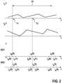
- Fig. 2 shows an exemplary phase current-time diagram for the in Fig. 1 illustrated method and the times of the current measurements of the respective phase currents carried out by means of the AD converter.
- the curves of the phase currents i a and i b over time t are shown.
- the duration of a PWM period 10 is shown, the PWM period 10 having a PWM start 11 and a PWM middle 12.
- the sampling behavior of a first AD converter AD1 and a second AD converter AD2 is shown, the first and second AD converter AD1 and AD2 each being able to sample all phase currents i a , i b and i c via current sensors if required.
- the current measurements are carried out both around the PWM start 11 and around the PWM middle 12.
- the phase current i a should be measured as often as possible, since this has the greatest information content. For this reason, the phase current i a two-fold and the phase current b i is performed by the first AD converter AD1 sampled only once by the PWM top 11 around, leading to the current values i a (0), i b (0) and i a (1) leads.
- the phase current i a around the PWM start 11 is measured by means of the second AD converter AD2, which accordingly leads to the current values i a (2), i a (3) and i a (4).
- phase currents i a and i b are sampled mirror-symmetrically to one another by the first AD converter AD1.
- the two measurements of the phase current i a thus frame the measurement of the phase current i b .
- the AD converters AD1 and AD2 scan slightly offset from one another.
- the division and implementation of the current measurements by the AD converters AD1 and AD2 is correspondingly repeated around the PWM center 12 and around the PWM start of the subsequent PWM period.
- phase current i a, i b and i c then finally to determine be necessary for the phase current i a detected current values i a (0), i a (1) i a (2) i a (3), and i a (4) averaged.
- phase current i of the detected current value b i b (0) are used and the phase current i c i calculated b means of the first Kirchhoff's law from the averaged phase current i a and the phase current.
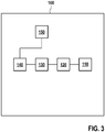
- Fig. 3 shows an exemplary embodiment of a multiphase electrical machine (100) which is set up to carry out a method according to the invention.
- the electrical machine 100 here has a stator-rotor unit 110.
- This stator-rotor unit 110 is fed by an inverter 120, which can be configured, for example, as a B6 bridge.
- the inverter 120 is in turn controlled by a PWM generating unit 130, which converts the specifications received from a current regulator 140 into corresponding PWM pulse duty factors.
- the current regulator 140 is set up to sample the phase currents i a , i b and i c of the stator-rotor unit 110, but this is not shown here.
- the electrical machine 100 can have a processing unit 150 which is set up to control the current regulation in such a way that the phase currents i a , i b and i c by means of the method according to the invention, for example in accordance with Fig. 1 , be determined.
Landscapes
- Engineering & Computer Science (AREA)
- Power Engineering (AREA)
- Control Of Ac Motors In General (AREA)
- Inverter Devices (AREA)
- Control Of Motors That Do Not Use Commutators (AREA)
Claims (9)
- Procédé de détermination de courants de phase (ia, ib, ic) d'une machine électrique rotative polyphasée, alimentée par un onduleur commandé par modulation de largeur d'impulsions (PWM), comprenant les étapes de procédé consistant à :a. déterminer des tensions d'injection à un instant pendant une période d'échantillonnage de régulateur, qui sont appliquées dans au moins une période PWM (10) après cet instant pour piloter la machine électrique, les tensions d'injection étant composées de tensions prédéfinies qui produisent un courant d'onde fondamentale correspondant et de tensions haute fréquence supplémentaires,b. déterminer une direction d'évaluation d'un vecteur de courant de phase de la machine électrique en fonction des tensions d'injection déterminées à l'étape a et/ou d'un point de fonctionnement de la machine électrique et/ou d'une dépendance par rapport à la température du vecteur de courant de phase,c. déterminer respectivement un nombre de mesures de courant pour chacun des courants de phase (ia, ib, ic) qui sont à effectuer dans au moins un état de commutation passif de l'onduleur à l'intérieur de ladite au moins une période PWM (10) en fonction de la direction d'évaluation déterminée à l'étape de procédé b,d. établir les courants de phase (ia, ib, ic) qui circulent dans ladite au moins une période PWM (10) dans la machine électrique en fonction du nombre de mesures de courant respectif déterminé à l'étape de procédé c.
- Procédé selon la revendication 1, caractérisé en ce que le nombre de mesures de courant qui est déterminé à l'étape de procédé c pour chaque courant de phase (ia, ib, ic) est déterminé, en somme pour tous les courants de phase (ia, ib, ic) d'un nombre possible au maximum de mesures de courant à l'intérieur de l'au moins un état de commutation passif de l'onduleur.
- Procédé selon l'une quelconque des revendications 1 ou 2, caractérisé en ce qu'à l'étape de procédé d, au moins l'un des courants de phase (ia, ib, ic) est déterminé au moyen de plusieurs convertisseurs A/D.
- Procédé selon la revendication 3, caractérisé en ce que l'établissement de l'au moins un courant de phase (ia, ib, ic) est effectué en ce que les plusieurs convertisseurs A/D échantillonnent ledit au moins un courant de phase (ia, ib, ic) en décalage dans le temps les uns par rapport aux autres.
- Procédé selon l'une quelconque des revendications 1 à 4, caractérisé en ce qu'à l'étape de procédé d, les mesures de courant sont effectuées au milieu de l'au moins un état de commutation passif.
- Procédé selon l'une quelconque des revendications 1 à 5, caractérisé en ce qu'à l'étape de procédé d, les mesures de courant des courants de phase respectifs (ia, ib, ic) sont effectuées de manière symétrique les unes par rapport aux autres.
- Procédé selon l'une quelconque des revendications 1 à 6, caractérisé en ce qu'à l'étape de procédé c, pour le courant de phase (ia, ib, ic) qui dévie, par rapport à la direction, le plus de la direction d'évaluation, le zéro est déterminé comme le nombre des mesures de courant, ce courant de phase (ia, ib, ic) étant établi à l'étape de procédé d en fonction des autres courants de phase (ia, ib, ic) au moyen de la première loi de Kirchhoff.
- Procédé selon l'une quelconque des revendications 1 à 7, caractérisé en ce qu'après l'étape de procédé d, une étape de procédé e et une étape de procédé f ont lieu, dans lequel, à l'étape de procédé e, une transformation de Clarke est déterminée en fonction du nombre des mesures de courant déterminé à l'étape de procédé c pour chacun des courants de phase (ia, ib, ic) et/ou en fonction de la direction d'évaluation déterminée à l'étape de procédé b, et dans lequel, à l'étape de procédé f, le vecteur de courant de phase est déterminé dans la direction d'évaluation en fonction de la transformation de Clarke et des courants de phase (ia, ib, ic) déterminés à l'étape de procédé d dont le nombre de mesures de courant est supérieur à zéro.
- Machine électrique (100), la machine électrique étant configurée de manière rotative et polyphasée et étant alimentée au moyen d'un onduleur commandé par PWM (120), caractérisée en ce que la machine électrique (100) est aménagée pour effectuer un procédé selon l'une quelconque des revendications 1 à 8.
Applications Claiming Priority (2)
| Application Number | Priority Date | Filing Date | Title |
|---|---|---|---|
| DE102017210071.0A DE102017210071A1 (de) | 2017-06-14 | 2017-06-14 | Verfahren zur Ermittlung von Phasenströmen einer mittels eines PWM-gesteuerten Wechselrichters gespeisten, rotierenden, mehrphasigen, elektrischen Maschine |
| PCT/EP2018/059865 WO2018228741A1 (fr) | 2017-06-14 | 2018-04-18 | Procédé de détermination de courants de phase d'une machine électrique, polyphasée, tournante et alimentée au moyen d'un onduleur à commande par modulation de largeur d'impulsions |
Publications (2)
| Publication Number | Publication Date |
|---|---|
| EP3639362A1 EP3639362A1 (fr) | 2020-04-22 |
| EP3639362B1 true EP3639362B1 (fr) | 2021-12-15 |
Family
ID=62002669
Family Applications (1)
| Application Number | Title | Priority Date | Filing Date |
|---|---|---|---|
| EP18718456.9A Active EP3639362B1 (fr) | 2017-06-14 | 2018-04-18 | Procédé de détermination de courants de phase d'une machine électrique rotative à polyphases entraînée par un pwm-onduleur |
Country Status (7)
| Country | Link |
|---|---|
| US (1) | US11283378B2 (fr) |
| EP (1) | EP3639362B1 (fr) |
| JP (1) | JP2020524971A (fr) |
| KR (1) | KR102549052B1 (fr) |
| CN (1) | CN110720174B (fr) |
| DE (1) | DE102017210071A1 (fr) |
| WO (1) | WO2018228741A1 (fr) |
Families Citing this family (4)
| Publication number | Priority date | Publication date | Assignee | Title |
|---|---|---|---|---|
| DE102019208497A1 (de) * | 2019-06-12 | 2020-12-17 | Robert Bosch Gmbh | Verfahren zur Bestimmung einer Rotorlage einer elektrischen, rotierenden Maschine sowie eine elektrische, rotierende Maschine zur Durchführung eines solchen Verfahrens |
| US11332029B2 (en) | 2020-01-31 | 2022-05-17 | Lear Corporation | Method and system for producing an active short circuit condition in an electric motor of a hybrid electric vehicle |
| US11167644B2 (en) | 2020-01-31 | 2021-11-09 | Lear Corporation | Method and system for notification of an active short circuit condition in an electric motor of a hybrid electric vehicle |
| US11462920B2 (en) | 2020-01-31 | 2022-10-04 | Lear Corporation | Method and system for producing an active short circuit condition in an electric motor of a hybrid electric vehicle |
Family Cites Families (21)
| Publication number | Priority date | Publication date | Assignee | Title |
|---|---|---|---|---|
| JP2728499B2 (ja) * | 1989-05-19 | 1998-03-18 | 株式会社日立製作所 | 電動機の速度制御装置 |
| JP3531701B2 (ja) * | 1996-04-11 | 2004-05-31 | 株式会社富士通ゼネラル | ブラシレスモータの制御方法 |
| KR100322256B1 (ko) * | 1998-09-18 | 2002-07-03 | 이종훈 | 공간전압벡터방식을이용한정지형여자시스템 |
| US20060071627A1 (en) * | 2002-03-28 | 2006-04-06 | Ho Eddy Y Y | Motor current reconstruction via DC bus current measurement |
| CN1639957A (zh) * | 2002-03-28 | 2005-07-13 | 国际整流器公司 | 经过直流总线电流测量的电动机电流重建 |
| FR2855677B1 (fr) * | 2003-05-30 | 2016-11-04 | Valeo Equip Electr Moteur | Circuit de commande a modulation en largeur d'impulsions pour machine electrique multi mode et machine electrique multi mode equipee d'un tel circuit de commande |
| US7525269B2 (en) | 2005-12-14 | 2009-04-28 | Gm Global Technology Operations, Inc. | Method and apparatus for sensorless position control of a permanent magnet synchronous motor (PMSM) drive system |
| JP4722002B2 (ja) * | 2006-09-26 | 2011-07-13 | 三菱電機株式会社 | Pwmインバータ制御装置及びpwmインバータ制御方法並びに冷凍空調装置 |
| KR100839074B1 (ko) * | 2006-12-26 | 2008-06-19 | 삼성전자주식회사 | 단일 전류센서를 사용한 3상 피더블유엠 인버터 시스템 |
| JP4895121B2 (ja) * | 2007-05-28 | 2012-03-14 | 本田技研工業株式会社 | インバータ装置 |
| EP2405570B1 (fr) * | 2010-07-07 | 2018-03-21 | Technische Universität Wien | Procédé et système pour suivre les saillances inhérentes des machines à courant alternatif |
| EP2603971B1 (fr) * | 2010-08-10 | 2014-12-10 | Ebm-Papst St. Georgen GmbH & CO. KG | Moteur à commutation électronique |
| JP5505259B2 (ja) * | 2010-10-28 | 2014-05-28 | 株式会社豊田中央研究所 | 回転電機制御システム |
| JP5615671B2 (ja) * | 2010-11-09 | 2014-10-29 | 株式会社コロナ | モータ制御装置およびモータ制御システム |
| JP5968805B2 (ja) * | 2013-02-28 | 2016-08-10 | 日立オートモティブシステムズ株式会社 | モータ装置およびモータ駆動装置 |
| GB2512078A (en) * | 2013-03-19 | 2014-09-24 | Control Tech Ltd | Control system for multi-phase rotary machines |
| JP6124723B2 (ja) * | 2013-07-23 | 2017-05-10 | 三菱電機株式会社 | 三相インバータの電流検出装置 |
| JP6390489B2 (ja) * | 2015-03-30 | 2018-09-19 | 株式会社デンソー | インバータの制御装置 |
| CN104767433B (zh) * | 2015-04-16 | 2016-04-27 | 曾菊阳 | 用于识别无感无刷电机初始位置的时变信号采样方法 |
| JP6590457B2 (ja) * | 2015-07-27 | 2019-10-16 | 株式会社Soken | 車両駆動制御装置及び車両駆動制御方法 |
| JP6341165B2 (ja) * | 2015-09-01 | 2018-06-13 | 株式会社安川電機 | 電力変換装置、相電流検出装置および相電流検出方法 |
-
2017
- 2017-06-14 DE DE102017210071.0A patent/DE102017210071A1/de not_active Withdrawn
-
2018
- 2018-04-18 WO PCT/EP2018/059865 patent/WO2018228741A1/fr unknown
- 2018-04-18 CN CN201880039476.2A patent/CN110720174B/zh active Active
- 2018-04-18 JP JP2019569487A patent/JP2020524971A/ja active Pending
- 2018-04-18 EP EP18718456.9A patent/EP3639362B1/fr active Active
- 2018-04-18 US US16/613,903 patent/US11283378B2/en active Active
- 2018-04-18 KR KR1020197036805A patent/KR102549052B1/ko active IP Right Grant
Also Published As
| Publication number | Publication date |
|---|---|
| CN110720174A (zh) | 2020-01-21 |
| WO2018228741A1 (fr) | 2018-12-20 |
| KR102549052B1 (ko) | 2023-06-30 |
| US11283378B2 (en) | 2022-03-22 |
| CN110720174B (zh) | 2023-03-07 |
| EP3639362A1 (fr) | 2020-04-22 |
| JP2020524971A (ja) | 2020-08-20 |
| DE102017210071A1 (de) | 2018-12-20 |
| KR20200014785A (ko) | 2020-02-11 |
| US20210408948A1 (en) | 2021-12-30 |
Similar Documents
| Publication | Publication Date | Title |
|---|---|---|
| EP3639362B1 (fr) | Procédé de détermination de courants de phase d'une machine électrique rotative à polyphases entraînée par un pwm-onduleur | |
| DE102009051923B4 (de) | Steuerungseinrichtung zum Berechnen einer elektrischen Leistungsaufnahme einer Industriemaschine | |
| EP2421148B1 (fr) | Dispositif et procédé d'identification des paramètres de référence mécaniques d'un moteur asynchrone triphasé sans utilisation d'encodeur de vitesse | |
| DE10243602B4 (de) | Leistungsumrichter, der zum Minimieren von Schaltungsverlusten entworfen ist | |
| EP3288179B1 (fr) | Procédé de détermination sans capteur de l'orientation du rotor d'un moteur pmsm sans fer | |
| DE102007054050A1 (de) | Halbleiter-Leistungsumsetzer | |
| DE102008018950A1 (de) | Verfahren und System zur Impulspositionsplanung bei Elektroantrieben | |
| DE112008001649T5 (de) | Pseudowechselrichter mit Stromzwischenkreis mit Leitung für 120 Grad | |
| WO2017045810A1 (fr) | Procédé d'identification de l'anisotropie magnétique d'une machine électrique à champ tournant | |
| EP2596577B1 (fr) | Procédé et dispositif de commande d'une machine électrique polyphasée, et système moteur | |
| EP2538547B1 (fr) | Dispositif et procédé d'identification de paramètres mécaniques d'un moteur linéaire asynchrone sans capteur de position | |
| DE102008052933A1 (de) | Verfahren zum Betreiben eines Elektromotors | |
| WO2007080004A1 (fr) | Procédé et dispositif de mesure de courant | |
| EP2577862A2 (fr) | Procédé et dispositif pour la détermination d'un passage par zéro d'un courant de phase d'une machine électrique commutée électroniquement, en particulier pour la détermination d'une position du rotor de la machine électrique | |
| EP1856792B2 (fr) | Détection de la position d'un rotor | |
| EP3984127B1 (fr) | Procédé de détermination d'une position de rotor d'une machine rotative électrique et machine rotative électrique pour la mise en oeuvre d'un tel procédé | |
| WO2019072327A1 (fr) | Procédé de démarrage et de fonctionnement d'un moteur sans balais et moteur sans balais | |
| EP1950882A2 (fr) | Procédé et dispositif de commande d'une machine à courant alternatif pouvant être commandée par modulation en largeur d'impulsion dotée de plusieurs enroulements de phase | |
| DE102008018075B4 (de) | Umrichter und Verfahren zur Bestimmung eines Stromraumzeigers | |
| DE102017220682A1 (de) | Steuereinrichtung für rotierende elektrische Wechselstrommaschine | |
| DE102013204382A1 (de) | Steuereinrichtung und Verfahren zum Ansteuern einer Drehfeldmaschine | |
| DE102020112913A1 (de) | Prädiktive Deadbeat-Regelung von Motorphasenströmen mit Modellfehlerkompensation und einstellbarer Regeldynamik | |
| EP0313929B1 (fr) | Méthode pour éviter une interruption de courant dans un toron, non utilisé pour la commutation d'une machine synchrone triphasée avec alimentation à bloc de courant et circuit d'utilisation pour cette méthode | |
| EP3297153B1 (fr) | Procédé et dispositif de détermination d'une position de rotor d'un rotor d'une machine électrique à commutation électronique | |
| EP1988402A2 (fr) | Procédé de détermination de travail/puissance |
Legal Events
| Date | Code | Title | Description |
|---|---|---|---|
| STAA | Information on the status of an ep patent application or granted ep patent |
Free format text: STATUS: UNKNOWN |
|
| STAA | Information on the status of an ep patent application or granted ep patent |
Free format text: STATUS: THE INTERNATIONAL PUBLICATION HAS BEEN MADE |
|
| PUAI | Public reference made under article 153(3) epc to a published international application that has entered the european phase |
Free format text: ORIGINAL CODE: 0009012 |
|
| STAA | Information on the status of an ep patent application or granted ep patent |
Free format text: STATUS: REQUEST FOR EXAMINATION WAS MADE |
|
| 17P | Request for examination filed |
Effective date: 20200114 |
|
| AK | Designated contracting states |
Kind code of ref document: A1 Designated state(s): AL AT BE BG CH CY CZ DE DK EE ES FI FR GB GR HR HU IE IS IT LI LT LU LV MC MK MT NL NO PL PT RO RS SE SI SK SM TR |
|
| AX | Request for extension of the european patent |
Extension state: BA ME |
|
| RAP1 | Party data changed (applicant data changed or rights of an application transferred) |
Owner name: ROBERT BOSCH GMBH |
|
| DAV | Request for validation of the european patent (deleted) | ||
| DAX | Request for extension of the european patent (deleted) | ||
| GRAP | Despatch of communication of intention to grant a patent |
Free format text: ORIGINAL CODE: EPIDOSNIGR1 |
|
| STAA | Information on the status of an ep patent application or granted ep patent |
Free format text: STATUS: GRANT OF PATENT IS INTENDED |
|
| INTG | Intention to grant announced |
Effective date: 20210913 |
|
| RIN1 | Information on inventor provided before grant (corrected) |
Inventor name: BENDEL, MICHAEL Inventor name: VOLLMER, ULRICH Inventor name: ROETZER, MARCO |
|
| GRAS | Grant fee paid |
Free format text: ORIGINAL CODE: EPIDOSNIGR3 |
|
| GRAA | (expected) grant |
Free format text: ORIGINAL CODE: 0009210 |
|
| STAA | Information on the status of an ep patent application or granted ep patent |
Free format text: STATUS: THE PATENT HAS BEEN GRANTED |
|
| AK | Designated contracting states |
Kind code of ref document: B1 Designated state(s): AL AT BE BG CH CY CZ DE DK EE ES FI FR GB GR HR HU IE IS IT LI LT LU LV MC MK MT NL NO PL PT RO RS SE SI SK SM TR |
|
| REG | Reference to a national code |
Ref country code: GB Ref legal event code: FG4D Free format text: NOT ENGLISH Ref country code: CH Ref legal event code: EP |
|
| REG | Reference to a national code |
Ref country code: IE Ref legal event code: FG4D Free format text: LANGUAGE OF EP DOCUMENT: GERMAN Ref country code: DE Ref legal event code: R096 Ref document number: 502018008208 Country of ref document: DE |
|
| REG | Reference to a national code |
Ref country code: AT Ref legal event code: REF Ref document number: 1456233 Country of ref document: AT Kind code of ref document: T Effective date: 20220115 |
|
| REG | Reference to a national code |
Ref country code: LT Ref legal event code: MG9D |
|
| REG | Reference to a national code |
Ref country code: NL Ref legal event code: MP Effective date: 20211215 |
|
| PG25 | Lapsed in a contracting state [announced via postgrant information from national office to epo] |
Ref country code: RS Free format text: LAPSE BECAUSE OF FAILURE TO SUBMIT A TRANSLATION OF THE DESCRIPTION OR TO PAY THE FEE WITHIN THE PRESCRIBED TIME-LIMIT Effective date: 20211215 Ref country code: LT Free format text: LAPSE BECAUSE OF FAILURE TO SUBMIT A TRANSLATION OF THE DESCRIPTION OR TO PAY THE FEE WITHIN THE PRESCRIBED TIME-LIMIT Effective date: 20211215 Ref country code: FI Free format text: LAPSE BECAUSE OF FAILURE TO SUBMIT A TRANSLATION OF THE DESCRIPTION OR TO PAY THE FEE WITHIN THE PRESCRIBED TIME-LIMIT Effective date: 20211215 Ref country code: BG Free format text: LAPSE BECAUSE OF FAILURE TO SUBMIT A TRANSLATION OF THE DESCRIPTION OR TO PAY THE FEE WITHIN THE PRESCRIBED TIME-LIMIT Effective date: 20220315 |
|
| PG25 | Lapsed in a contracting state [announced via postgrant information from national office to epo] |
Ref country code: SE Free format text: LAPSE BECAUSE OF FAILURE TO SUBMIT A TRANSLATION OF THE DESCRIPTION OR TO PAY THE FEE WITHIN THE PRESCRIBED TIME-LIMIT Effective date: 20211215 Ref country code: NO Free format text: LAPSE BECAUSE OF FAILURE TO SUBMIT A TRANSLATION OF THE DESCRIPTION OR TO PAY THE FEE WITHIN THE PRESCRIBED TIME-LIMIT Effective date: 20220315 Ref country code: LV Free format text: LAPSE BECAUSE OF FAILURE TO SUBMIT A TRANSLATION OF THE DESCRIPTION OR TO PAY THE FEE WITHIN THE PRESCRIBED TIME-LIMIT Effective date: 20211215 Ref country code: HR Free format text: LAPSE BECAUSE OF FAILURE TO SUBMIT A TRANSLATION OF THE DESCRIPTION OR TO PAY THE FEE WITHIN THE PRESCRIBED TIME-LIMIT Effective date: 20211215 Ref country code: GR Free format text: LAPSE BECAUSE OF FAILURE TO SUBMIT A TRANSLATION OF THE DESCRIPTION OR TO PAY THE FEE WITHIN THE PRESCRIBED TIME-LIMIT Effective date: 20220316 |
|
| PG25 | Lapsed in a contracting state [announced via postgrant information from national office to epo] |
Ref country code: NL Free format text: LAPSE BECAUSE OF FAILURE TO SUBMIT A TRANSLATION OF THE DESCRIPTION OR TO PAY THE FEE WITHIN THE PRESCRIBED TIME-LIMIT Effective date: 20211215 |
|
| PG25 | Lapsed in a contracting state [announced via postgrant information from national office to epo] |
Ref country code: SM Free format text: LAPSE BECAUSE OF FAILURE TO SUBMIT A TRANSLATION OF THE DESCRIPTION OR TO PAY THE FEE WITHIN THE PRESCRIBED TIME-LIMIT Effective date: 20211215 Ref country code: SK Free format text: LAPSE BECAUSE OF FAILURE TO SUBMIT A TRANSLATION OF THE DESCRIPTION OR TO PAY THE FEE WITHIN THE PRESCRIBED TIME-LIMIT Effective date: 20211215 Ref country code: RO Free format text: LAPSE BECAUSE OF FAILURE TO SUBMIT A TRANSLATION OF THE DESCRIPTION OR TO PAY THE FEE WITHIN THE PRESCRIBED TIME-LIMIT Effective date: 20211215 Ref country code: PT Free format text: LAPSE BECAUSE OF FAILURE TO SUBMIT A TRANSLATION OF THE DESCRIPTION OR TO PAY THE FEE WITHIN THE PRESCRIBED TIME-LIMIT Effective date: 20220418 Ref country code: ES Free format text: LAPSE BECAUSE OF FAILURE TO SUBMIT A TRANSLATION OF THE DESCRIPTION OR TO PAY THE FEE WITHIN THE PRESCRIBED TIME-LIMIT Effective date: 20211215 Ref country code: EE Free format text: LAPSE BECAUSE OF FAILURE TO SUBMIT A TRANSLATION OF THE DESCRIPTION OR TO PAY THE FEE WITHIN THE PRESCRIBED TIME-LIMIT Effective date: 20211215 Ref country code: CZ Free format text: LAPSE BECAUSE OF FAILURE TO SUBMIT A TRANSLATION OF THE DESCRIPTION OR TO PAY THE FEE WITHIN THE PRESCRIBED TIME-LIMIT Effective date: 20211215 |
|
| PG25 | Lapsed in a contracting state [announced via postgrant information from national office to epo] |
Ref country code: PL Free format text: LAPSE BECAUSE OF FAILURE TO SUBMIT A TRANSLATION OF THE DESCRIPTION OR TO PAY THE FEE WITHIN THE PRESCRIBED TIME-LIMIT Effective date: 20211215 |
|
| REG | Reference to a national code |
Ref country code: DE Ref legal event code: R097 Ref document number: 502018008208 Country of ref document: DE |
|
| PG25 | Lapsed in a contracting state [announced via postgrant information from national office to epo] |
Ref country code: IS Free format text: LAPSE BECAUSE OF FAILURE TO SUBMIT A TRANSLATION OF THE DESCRIPTION OR TO PAY THE FEE WITHIN THE PRESCRIBED TIME-LIMIT Effective date: 20220415 |
|
| PLBE | No opposition filed within time limit |
Free format text: ORIGINAL CODE: 0009261 |
|
| STAA | Information on the status of an ep patent application or granted ep patent |
Free format text: STATUS: NO OPPOSITION FILED WITHIN TIME LIMIT |
|
| PG25 | Lapsed in a contracting state [announced via postgrant information from national office to epo] |
Ref country code: DK Free format text: LAPSE BECAUSE OF FAILURE TO SUBMIT A TRANSLATION OF THE DESCRIPTION OR TO PAY THE FEE WITHIN THE PRESCRIBED TIME-LIMIT Effective date: 20211215 Ref country code: AL Free format text: LAPSE BECAUSE OF FAILURE TO SUBMIT A TRANSLATION OF THE DESCRIPTION OR TO PAY THE FEE WITHIN THE PRESCRIBED TIME-LIMIT Effective date: 20211215 |
|
| 26N | No opposition filed |
Effective date: 20220916 |
|
| PG25 | Lapsed in a contracting state [announced via postgrant information from national office to epo] |
Ref country code: SI Free format text: LAPSE BECAUSE OF FAILURE TO SUBMIT A TRANSLATION OF THE DESCRIPTION OR TO PAY THE FEE WITHIN THE PRESCRIBED TIME-LIMIT Effective date: 20211215 |
|
| REG | Reference to a national code |
Ref country code: CH Ref legal event code: PL |
|
| GBPC | Gb: european patent ceased through non-payment of renewal fee |
Effective date: 20220418 |
|
| REG | Reference to a national code |
Ref country code: BE Ref legal event code: MM Effective date: 20220430 |
|
| PG25 | Lapsed in a contracting state [announced via postgrant information from national office to epo] |
Ref country code: MC Free format text: LAPSE BECAUSE OF FAILURE TO SUBMIT A TRANSLATION OF THE DESCRIPTION OR TO PAY THE FEE WITHIN THE PRESCRIBED TIME-LIMIT Effective date: 20211215 Ref country code: LU Free format text: LAPSE BECAUSE OF NON-PAYMENT OF DUE FEES Effective date: 20220418 Ref country code: LI Free format text: LAPSE BECAUSE OF NON-PAYMENT OF DUE FEES Effective date: 20220430 Ref country code: GB Free format text: LAPSE BECAUSE OF NON-PAYMENT OF DUE FEES Effective date: 20220418 Ref country code: CH Free format text: LAPSE BECAUSE OF NON-PAYMENT OF DUE FEES Effective date: 20220430 |
|
| PG25 | Lapsed in a contracting state [announced via postgrant information from national office to epo] |
Ref country code: BE Free format text: LAPSE BECAUSE OF NON-PAYMENT OF DUE FEES Effective date: 20220430 |
|
| PG25 | Lapsed in a contracting state [announced via postgrant information from national office to epo] |
Ref country code: IE Free format text: LAPSE BECAUSE OF NON-PAYMENT OF DUE FEES Effective date: 20220418 |
|
| PGFP | Annual fee paid to national office [announced via postgrant information from national office to epo] |
Ref country code: IT Payment date: 20230428 Year of fee payment: 6 Ref country code: FR Payment date: 20230417 Year of fee payment: 6 Ref country code: DE Payment date: 20230627 Year of fee payment: 6 |
|
| PG25 | Lapsed in a contracting state [announced via postgrant information from national office to epo] |
Ref country code: MK Free format text: LAPSE BECAUSE OF FAILURE TO SUBMIT A TRANSLATION OF THE DESCRIPTION OR TO PAY THE FEE WITHIN THE PRESCRIBED TIME-LIMIT Effective date: 20211215 Ref country code: CY Free format text: LAPSE BECAUSE OF FAILURE TO SUBMIT A TRANSLATION OF THE DESCRIPTION OR TO PAY THE FEE WITHIN THE PRESCRIBED TIME-LIMIT Effective date: 20211215 |