EP3638534B1 - Systems and methods for reducing parasitic power losses by an energy source - Google Patents
Systems and methods for reducing parasitic power losses by an energy source Download PDFInfo
- Publication number
- EP3638534B1 EP3638534B1 EP18818761.1A EP18818761A EP3638534B1 EP 3638534 B1 EP3638534 B1 EP 3638534B1 EP 18818761 A EP18818761 A EP 18818761A EP 3638534 B1 EP3638534 B1 EP 3638534B1
- Authority
- EP
- European Patent Office
- Prior art keywords
- voltage
- battery
- power
- battery pack
- systems
- Prior art date
- Legal status (The legal status is an assumption and is not a legal conclusion. Google has not performed a legal analysis and makes no representation as to the accuracy of the status listed.)
- Active
Links
- 230000003071 parasitic effect Effects 0.000 title claims description 46
- 238000000034 method Methods 0.000 title claims description 9
- 238000007726 management method Methods 0.000 description 21
- 238000010586 diagram Methods 0.000 description 19
- 238000004891 communication Methods 0.000 description 9
- 238000006243 chemical reaction Methods 0.000 description 7
- 238000009826 distribution Methods 0.000 description 6
- 230000001276 controlling effect Effects 0.000 description 5
- WHXSMMKQMYFTQS-UHFFFAOYSA-N Lithium Chemical compound [Li] WHXSMMKQMYFTQS-UHFFFAOYSA-N 0.000 description 4
- HBBGRARXTFLTSG-UHFFFAOYSA-N Lithium ion Chemical compound [Li+] HBBGRARXTFLTSG-UHFFFAOYSA-N 0.000 description 4
- 238000010292 electrical insulation Methods 0.000 description 4
- 229910052744 lithium Inorganic materials 0.000 description 4
- 229910001416 lithium ion Inorganic materials 0.000 description 4
- XLYOFNOQVPJJNP-UHFFFAOYSA-N water Substances O XLYOFNOQVPJJNP-UHFFFAOYSA-N 0.000 description 4
- 230000009977 dual effect Effects 0.000 description 3
- 239000000463 material Substances 0.000 description 3
- JDZCKJOXGCMJGS-UHFFFAOYSA-N [Li].[S] Chemical compound [Li].[S] JDZCKJOXGCMJGS-UHFFFAOYSA-N 0.000 description 2
- 238000001514 detection method Methods 0.000 description 2
- 230000036541 health Effects 0.000 description 2
- 239000011159 matrix material Substances 0.000 description 2
- 238000005259 measurement Methods 0.000 description 2
- 229920000642 polymer Polymers 0.000 description 2
- 230000001105 regulatory effect Effects 0.000 description 2
- 238000003860 storage Methods 0.000 description 2
- 241001131796 Botaurus stellaris Species 0.000 description 1
- PEDCQBHIVMGVHV-UHFFFAOYSA-N Glycerine Chemical compound OCC(O)CO PEDCQBHIVMGVHV-UHFFFAOYSA-N 0.000 description 1
- 230000001133 acceleration Effects 0.000 description 1
- 238000003491 array Methods 0.000 description 1
- 238000013475 authorization Methods 0.000 description 1
- 230000005779 cell damage Effects 0.000 description 1
- 208000037887 cell injury Diseases 0.000 description 1
- 230000006835 compression Effects 0.000 description 1
- 238000007906 compression Methods 0.000 description 1
- 230000003750 conditioning effect Effects 0.000 description 1
- 238000007599 discharging Methods 0.000 description 1
- 238000004880 explosion Methods 0.000 description 1
- 239000013505 freshwater Substances 0.000 description 1
- 230000006870 function Effects 0.000 description 1
- 238000004519 manufacturing process Methods 0.000 description 1
- 238000012544 monitoring process Methods 0.000 description 1
- 238000005192 partition Methods 0.000 description 1
- 238000009304 pastoral farming Methods 0.000 description 1
- 238000012805 post-processing Methods 0.000 description 1
- 238000012545 processing Methods 0.000 description 1
- 239000000047 product Substances 0.000 description 1
- 238000006467 substitution reaction Methods 0.000 description 1
- 239000013589 supplement Substances 0.000 description 1
Images


Classifications
-
- B—PERFORMING OPERATIONS; TRANSPORTING
- B63—SHIPS OR OTHER WATERBORNE VESSELS; RELATED EQUIPMENT
- B63G—OFFENSIVE OR DEFENSIVE ARRANGEMENTS ON VESSELS; MINE-LAYING; MINE-SWEEPING; SUBMARINES; AIRCRAFT CARRIERS
- B63G8/00—Underwater vessels, e.g. submarines; Equipment specially adapted therefor
- B63G8/08—Propulsion
-
- B—PERFORMING OPERATIONS; TRANSPORTING
- B60—VEHICLES IN GENERAL
- B60L—PROPULSION OF ELECTRICALLY-PROPELLED VEHICLES; SUPPLYING ELECTRIC POWER FOR AUXILIARY EQUIPMENT OF ELECTRICALLY-PROPELLED VEHICLES; ELECTRODYNAMIC BRAKE SYSTEMS FOR VEHICLES IN GENERAL; MAGNETIC SUSPENSION OR LEVITATION FOR VEHICLES; MONITORING OPERATING VARIABLES OF ELECTRICALLY-PROPELLED VEHICLES; ELECTRIC SAFETY DEVICES FOR ELECTRICALLY-PROPELLED VEHICLES
- B60L50/00—Electric propulsion with power supplied within the vehicle
- B60L50/50—Electric propulsion with power supplied within the vehicle using propulsion power supplied by batteries or fuel cells
- B60L50/60—Electric propulsion with power supplied within the vehicle using propulsion power supplied by batteries or fuel cells using power supplied by batteries
- B60L50/66—Arrangements of batteries
-
- B—PERFORMING OPERATIONS; TRANSPORTING
- B63—SHIPS OR OTHER WATERBORNE VESSELS; RELATED EQUIPMENT
- B63G—OFFENSIVE OR DEFENSIVE ARRANGEMENTS ON VESSELS; MINE-LAYING; MINE-SWEEPING; SUBMARINES; AIRCRAFT CARRIERS
- B63G8/00—Underwater vessels, e.g. submarines; Equipment specially adapted therefor
- B63G8/001—Underwater vessels adapted for special purposes, e.g. unmanned underwater vessels; Equipment specially adapted therefor, e.g. docking stations
-
- H—ELECTRICITY
- H02—GENERATION; CONVERSION OR DISTRIBUTION OF ELECTRIC POWER
- H02J—CIRCUIT ARRANGEMENTS OR SYSTEMS FOR SUPPLYING OR DISTRIBUTING ELECTRIC POWER; SYSTEMS FOR STORING ELECTRIC ENERGY
- H02J1/00—Circuit arrangements for dc mains or dc distribution networks
- H02J1/08—Three-wire systems; Systems having more than three wires
- H02J1/082—Plural DC voltage, e.g. DC supply voltage with at least two different DC voltage levels
-
- H—ELECTRICITY
- H02—GENERATION; CONVERSION OR DISTRIBUTION OF ELECTRIC POWER
- H02J—CIRCUIT ARRANGEMENTS OR SYSTEMS FOR SUPPLYING OR DISTRIBUTING ELECTRIC POWER; SYSTEMS FOR STORING ELECTRIC ENERGY
- H02J7/00—Circuit arrangements for charging or depolarising batteries or for supplying loads from batteries
- H02J7/0063—Circuit arrangements for charging or depolarising batteries or for supplying loads from batteries with circuits adapted for supplying loads from the battery
-
- B—PERFORMING OPERATIONS; TRANSPORTING
- B60—VEHICLES IN GENERAL
- B60L—PROPULSION OF ELECTRICALLY-PROPELLED VEHICLES; SUPPLYING ELECTRIC POWER FOR AUXILIARY EQUIPMENT OF ELECTRICALLY-PROPELLED VEHICLES; ELECTRODYNAMIC BRAKE SYSTEMS FOR VEHICLES IN GENERAL; MAGNETIC SUSPENSION OR LEVITATION FOR VEHICLES; MONITORING OPERATING VARIABLES OF ELECTRICALLY-PROPELLED VEHICLES; ELECTRIC SAFETY DEVICES FOR ELECTRICALLY-PROPELLED VEHICLES
- B60L2200/00—Type of vehicles
- B60L2200/32—Waterborne vessels
-
- B—PERFORMING OPERATIONS; TRANSPORTING
- B60—VEHICLES IN GENERAL
- B60L—PROPULSION OF ELECTRICALLY-PROPELLED VEHICLES; SUPPLYING ELECTRIC POWER FOR AUXILIARY EQUIPMENT OF ELECTRICALLY-PROPELLED VEHICLES; ELECTRODYNAMIC BRAKE SYSTEMS FOR VEHICLES IN GENERAL; MAGNETIC SUSPENSION OR LEVITATION FOR VEHICLES; MONITORING OPERATING VARIABLES OF ELECTRICALLY-PROPELLED VEHICLES; ELECTRIC SAFETY DEVICES FOR ELECTRICALLY-PROPELLED VEHICLES
- B60L53/00—Methods of charging batteries, specially adapted for electric vehicles; Charging stations or on-board charging equipment therefor; Exchange of energy storage elements in electric vehicles
-
- B—PERFORMING OPERATIONS; TRANSPORTING
- B63—SHIPS OR OTHER WATERBORNE VESSELS; RELATED EQUIPMENT
- B63G—OFFENSIVE OR DEFENSIVE ARRANGEMENTS ON VESSELS; MINE-LAYING; MINE-SWEEPING; SUBMARINES; AIRCRAFT CARRIERS
- B63G8/00—Underwater vessels, e.g. submarines; Equipment specially adapted therefor
- B63G8/001—Underwater vessels adapted for special purposes, e.g. unmanned underwater vessels; Equipment specially adapted therefor, e.g. docking stations
- B63G2008/002—Underwater vessels adapted for special purposes, e.g. unmanned underwater vessels; Equipment specially adapted therefor, e.g. docking stations unmanned
- B63G2008/004—Underwater vessels adapted for special purposes, e.g. unmanned underwater vessels; Equipment specially adapted therefor, e.g. docking stations unmanned autonomously operating
-
- H—ELECTRICITY
- H02—GENERATION; CONVERSION OR DISTRIBUTION OF ELECTRIC POWER
- H02J—CIRCUIT ARRANGEMENTS OR SYSTEMS FOR SUPPLYING OR DISTRIBUTING ELECTRIC POWER; SYSTEMS FOR STORING ELECTRIC ENERGY
- H02J2310/00—The network for supplying or distributing electric power characterised by its spatial reach or by the load
- H02J2310/40—The network being an on-board power network, i.e. within a vehicle
- H02J2310/42—The network being an on-board power network, i.e. within a vehicle for ships or vessels
-
- Y—GENERAL TAGGING OF NEW TECHNOLOGICAL DEVELOPMENTS; GENERAL TAGGING OF CROSS-SECTIONAL TECHNOLOGIES SPANNING OVER SEVERAL SECTIONS OF THE IPC; TECHNICAL SUBJECTS COVERED BY FORMER USPC CROSS-REFERENCE ART COLLECTIONS [XRACs] AND DIGESTS
- Y02—TECHNOLOGIES OR APPLICATIONS FOR MITIGATION OR ADAPTATION AGAINST CLIMATE CHANGE
- Y02T—CLIMATE CHANGE MITIGATION TECHNOLOGIES RELATED TO TRANSPORTATION
- Y02T10/00—Road transport of goods or passengers
- Y02T10/60—Other road transportation technologies with climate change mitigation effect
- Y02T10/70—Energy storage systems for electromobility, e.g. batteries
-
- Y—GENERAL TAGGING OF NEW TECHNOLOGICAL DEVELOPMENTS; GENERAL TAGGING OF CROSS-SECTIONAL TECHNOLOGIES SPANNING OVER SEVERAL SECTIONS OF THE IPC; TECHNICAL SUBJECTS COVERED BY FORMER USPC CROSS-REFERENCE ART COLLECTIONS [XRACs] AND DIGESTS
- Y02—TECHNOLOGIES OR APPLICATIONS FOR MITIGATION OR ADAPTATION AGAINST CLIMATE CHANGE
- Y02T—CLIMATE CHANGE MITIGATION TECHNOLOGIES RELATED TO TRANSPORTATION
- Y02T90/00—Enabling technologies or technologies with a potential or indirect contribution to GHG emissions mitigation
- Y02T90/10—Technologies relating to charging of electric vehicles
- Y02T90/14—Plug-in electric vehicles
Definitions
- Typical battery power systems use a down converter circuit to provide power to parasitic systems that supplement the battery in some manner, resulting in unacceptable power discharge and shortened battery life. Because all batteries have some internal resistance, any amount of current drawn from a battery results in some amount of energy loss based on I 2 R power losses. Also, a typical voltage down converter includes a resistance clement to create a voltage drop that reduces the output voltage from a power source. Again, such a voltage drop across the down converting resister results in further IV power losses.
- Parasitic losses may be incurred by hotel loads (other low voltage circuits and systems) and circuit components (e.g., diodes). Even a relatively small amount of parasitic current form a high voltage power source can result in a substantial amount of I 2 R power losses over a relatively short period of time which, in turn, results in a substantially reduced operational time for an unmanned underwater vehicle over the course of a mission. Hence, there is a need to reduce power losses associated with down converting and powering lower voltage parasitic systems within underwater vehicles to extend the operational up time of underwater vehicles before battery recharge is required.
- FR 3026384A1 discloses an underwater vehicle equipped with an electrical energy supply network having at least two sources of DC voltage based on lithium-ion batteries where a first source supplies a first voltage and a second source supplies a second voltage.
- a switching means is connected to each DC voltage source that enables the supply network to deliver one of three output DC voltages: a first voltage from the first source, second voltage from the second source, and a third voltage based on the sum of the first voltage and the second voltage.
- US 2015/274027A1 describes a first battery configured to power at least one vehicle subsystem and a second battery configured to power an electric motor to propel a vehicle.
- a processing device is configured to detect an inadequate power level provided from the first battery to the at least one vehicle subsystem and selectively partition the second battery to power the at least one vehicle subsystem.
- US 2016/039300A1 discloses systems and methods for swapping the battery on an unmanned aerial vehicle (UAV) while providing continuous power to at least one system on the UAV.
- UAV unmanned aerial vehicle
- US 2016/318411A1 describes a battery system that has at least one battery with a plurality of battery elements, a regulating or control unit and a switching unit with at least one switching element.
- the regulating or control unit is configured to instruct the switching unit to dynamically switch the switching element over time such that battery elements from a dynamically changing subset of the plurality of battery elements with a respective voltage level to providing a plurality of voltage levels as desired.
- a power system can include a first battery module and a second battery module.
- the first battery module operates at a first voltage and the second battery module operates at a second voltage.
- the first battery module delivers power to a plurality of primary systems.
- the second battery module delivers power to a plurality of parasitic systems.
- a power system for an autonomous vehicle includes a first battery module and a second battery module.
- the first battery module operates at a first voltage and the second battery module operates at a second voltage.
- the first battery module delivers power to a plurality of primary systems.
- the second battery module delivers power to a plurality of parasitic systems.
- Parasitic systems may include, for example, one or more processors and/or controllers, one or more sensors, one or more switches, one or more low voltage servos or motors, one or more monitoring or scientific instruments (e.g., camera systems, lighting systems, etc...), one or more communications circuits, and one or more electronic systems using a voltage that is lower than a primary output voltage from a battery system.
- the one or more processors and/or controllers may include circuitry and/or software to control one or functions of an unmanned underwater vehicle.
- the first or primary voltage is nominally 300 V.
- the first voltage may be any relatively higher voltage in relation to a secondary or parasitic voltage.
- the nominal primary voltage may be a factor higher than the secondary voltage.
- the factor may be 2,3,4,5, 10,20,50, 100, and so on.
- the primary voltage may greater than or equal to about 50 V, 75 V, 100 V, 200 V, 300 V, 400 V, 500 V, 600 V, and 1000V.
- the second or nominal secondary voltage is 30 V.
- the nominal secondary voltage may less than or equal to about 1. V, 2 V, 3 V, 4 V, 5 V, 10 V, 20 V, 30 V, 50 V, and 100 V.
- the need for using a voltage down converter to reduce the first voltage to the second voltage is eliminated.
- the I 2 R power losses caused by parasitic current drawn from the first battery' module through the down converter are eliminated, reducing the parasitic losses of the power system.
- the second battery module has its own internal resistance, the I 2 R power losses incurred drawing parasitic current from the second battery module is substantially lower than the I 2 R power losses that would otherwise have been incurred by the first battery module using a down converter.
- the configuration utilizing a second battery module to provide power to parasitic components and/or circuits advantageously preserves more power for both the first battery module and second battery modules and, thereby, advantageously extends to operational time of the unmanned underwater vehicle before re-charge of the battery modules is needed.
- FIG. 1 is a block diagram depicting an illustrative remote vehicle, according to an illustrative aspect of the present disclosure.
- the system 100 includes a sonar unit 110 for sending and receiving sonar signals, a preprocessor 120 for conditioning a received (or reflected) signal, and a matched filter 130 for performing pulse compression and beamforming.
- the system 100 is configured to allow for navigating using high-frequency (greater than about 100 kHz) sonar signals. To allow for such HF navigation, the system 100 includes a signal corrector 140 for compensating for grazing angle error and for correcting phase error.
- the system 100 also includes a signal detector 150 for coherently correlating a received image with a map.
- the system 100 includes an on-board navigation controller 170, motor controller 180 and sensor controller 190.
- the navigation controller 170 may be configured to receive navigational parameters from a GPS/RF link 172 (when available), an accelerometer 174, a gyroscope, and a compass 176.
- the motor controller 180 may be configured to control a plurality of motors 182, 184 and 186 for steering the vehicle.
- the sensor controller 190 may receive measurements from the battery monitor 172, a temperature sensor 194 and a pressure sensor 196.
- the system 100 further includes a central control unit (CCU) 160 that may serve as a hub for determining navigational parameters based on sonar measurements and other navigational and sensor parameters, and for controlling the movement of the vehicle.
- CCU central control unit
- the CCU 160 may determine navigational parameters such as position (latitude and longitude), velocity (in any direction), bearing, heading, acceleration and altitude.
- the CCU 160 may use these navigational parameters for controlling motion along the alongtrack direction (fore and aft), acrosstrack direction (port and starboard), and vertical direction (up and down).
- the CCU 160 may use these navigational parameters for controlling motion to yaw, pitch, roll or otherwise rotate the vehicle.
- the system 100 includes a sonar unit 110 for transmitting and receiving acoustic signals.
- the sonar unit includes a transducer array 112 having a one or more transmitting elements or projectors and a plurality of receiving elements arranged in a row.
- the transducer array 112 includes separate projectors and receivers.
- the transducer array 112 may be configured to operate in SAS mode (either stripmap or spotlight mode) or in a real aperture mode.
- the transducer array 112 is configured to operate as a multibeam echo sounder, sidescan sonar or sectors can sonar.
- One example of an array 112 includes a 16 channel array with 5 cm elements mounted in a 12 % inch vehicle.
- the system 100 may include other components, not illustrated, without departing from the scope of the present disclosure.
- the system 100 may include a data logging and storage engine.
- the data logging and storage engine may be used to store scientific data which may then be used in post-processing for assisting with navigation.
- the system 100 may include a security engine for controlling access to and for authorizing the use of one or more features of system 100.
- the security engine may be configured with suitable encryption protocols and/or security keys and/or dongles for controlling access.
- the security engine may be used to protect one or more maps stored in the map store 154. Access to one or more maps in the map store 154 may be limited to certain individuals or entities having appropriate licenses, authorizations or clearances.
- Security engine may selectively allow these individuals or entities access to one or more maps once it has confirmed that these individuals or entities are authorized.
- the security engine may be configured to control access to other components of system 100 including, but not limited to, navigation controller 170, motor controller 180, sensor controller 190, transmitter controller 118, and CCU 160.
- the system may include an inertial navigation system, a Doppler sensor, an altimeter, a gimbling system to fixate the sensor on a populated portion of a holographic map, a global positioning system (GPS), a long baseline (LBL) navigation system, an ultrashort baseline (USBL) navigation, or any other suitable navigation system.
- GPS global positioning system
- LBL long baseline
- USBL ultrashort baseline
- FIG. 3 is a block diagram depicting an exemplary remote vehicle, according to an illustrative aspect of the present disclosure.
- Such an exemplary remote or autonomous vehicle includes a main body 302, along with a drive unit 304.
- the drive unit 304 may be a propeller.
- the remote vehicle includes internal components, which may be located within different compartments within the main body 302.
- the main body 302 may house a component 306.
- the component 306 may be a sonar unit.
- the main body 302 may house a pressure tolerant energy system 310, which may include a computer system, as described for example in FIG. 1 and FIG. 2 .
- the remote or autonomous vehicle includes a power generating system 308.
- the power generating system 308 may be a stack of battery elements, each comprising a stack of battery cells.
- a series connection (with or without other parallel connections) may be required to meet specific power requirements. Any imbalance between cells may affect battery performance, If charging cells in series, charging is only desirable until one of the cells reaches its maximum cell voltage - proceeding with charging beyond that point would result in cell damage and/or may cause fire or explosion through the battery.
- a vehicle for example an underwater vehicle, may be powered by an array of battery packs, each battery pack comprising battery cells.
- cells may comprise any suitable battery for providing energy to a vehicle, including, but not limited to, any suitable battery chemistry, a lithium battery, lithium-ion battery, lithium polymer battery, or a lithium sulfur battery.
- the battery cells may be in a matrix, or the battery cells may be arranged, aligned, or positioned in any suitable arrangement.
- the battery cells may be stacked on top of each other.
- the battery cells may include a separator between each vertically-stacked cell.
- the one or more battery cells may be positioned on a tray, wherein the tray provides structural support, alignment, and electrical insulation for the one or more battery cells.
- a backplane may connect the battery cells to management circuitry, described in further detail below.
- battery cells may be directly connected to the management circuitry.
- the battery cells may be connected to management circuitry through a communication network.
- a communication network may be any suitable network for communicating control signals.
- the management circuitry may comprise a pressure tolerant circuit board that may be manually programmed using any suitable programming language.
- a temperature sensor may be connected to the battery cells, either directly or through backplane.
- the battery cells may be configured to communicate cell health information, including at least a voltage and temperature, to the management circuitry.
- the management circuitry may include a water-intrusion detection circuit board, which may comprise a conductive trace that drops in resistance in the presence of water.
- a battery manager may be configured to interface with the outside world and to protect the battery (by disconnecting the charge input and/or discharge output) if voltage or temperature safety limits are exceeded.
- the BMGR may shut down the battery immediately if it detects any individual cell voltage above the max cell voltage, or if any individual cell temperature exceeds a manufacturer recommended maximum temperature.
- the BMGR may disable charging of the battery system if any cell temperature is below a manufacturer recommended minimum temperature.
- the BMGR may disable discharging of the battery system if any cell temperature is below a manufacturer recommended minimum temperature for discharge, which may differ from the charge limit temperature.
- An over-discharge protection feature may be activated at any time, which will also shut down the battery if any individual cell voltage drops below a manufacturer recommended minimum cell voltage.
- the battery system may be equipped with a pressure tolerant fuse in series with the positive terminal, and the BMGR may provide a controllable dual disconnect (high and low side switches). Further details regarding an exemplary pressure tolerant fuse are provided in U.S. Patent Application Publication No. 2012/0281503 . This provides a safety feature by requiring two concurrent failures to happen before an uncommanded output voltage can be presented at the battery output.
- FIG. 4 is a block diagram depicting an illustrative example of a pressure tolerant energy system, such as the pressure tolerant energy system 310 depicted in FIG. 3 .
- the pressure tolerant energy system 310 may comprise one or more battery cells 402, tray 404, electrical connections 406, backplane 408, communication network 410, management circuitry 412, a temperature sensor 414, and a multi-level battery protection system 416, and a suitable enclosure.
- the battery cells 402 may comprise any suitable battery for providing energy to an underwater vehicle, including, but not limited to, a lithium battery, lithium-ion battery, lithium polymer battery, or a lithium sulfur battery.
- the battery• cells 402 may be neutrally buoyant (e.g., compared to fresh water or sea/ocean water).
- the battery cells 402 are depicted in FIG. 4 in a 3x2 matrix, the battery cells 402 may be arranged, aligned, or positioned in any suitable arrangement.
- the battery cells 402 may be stacked on top of each other. In such aspects, the battery cells 402 may include a separator between each vertically-stacked cell.
- the battery cells 402 may be placed into tray 404.
- the tray 404 may be made from any suitable material, such as thermoformed plastic.
- the tray 404 may provide structural support, alignment, and electrical insulation for the battery cells 402.
- the tray may be placed in an enclosure to support multiple trays stacked upon each other.
- the battery cells 402 may be electrically and/or structurally connected to backplane 408.
- the backplane may provide both structural support and alignment for the battery cells 402.
- the backplane may also connect to an energy distribution system, such as energy distribution system 312 depicted in FIG. 3 .
- the battery cells 402 may be connected directly to an energy distribution system.
- the backplane may connect the battery cells 402 to the management circuitry 412.
- battery cells 402 may be directly connected to the management circuitry 412.
- the battery cells 402 may be connected to management circuitry 412 through communication network 410.
- Communication network 410 may be any suitable network for communicating control signals.
- the management circuitry 412 may comprise a pressure tolerant circuit board that may be manually programmed using any suitable programming language.
- a temperature sensor may be connected to the battery cells 402, either directly or through backplane 408.
- the battery cells 402 may be configured to communicate cell health information, including at least a voltage and temperature, to the management circuitry 412.
- the management circuitry 412 may include a water-intrusion detection circuit board, which may comprise a conductive trace that drops in resistance in the presence of water.
- the battery cells 402 may be connected to the multi-level battery protection system 416.
- the multi-level battery protection system may comprise fuses at the junction box and at each battery cell as well as a current limiting circuit (CLC) and a microprocessor circuit.
- CLC current limiting circuit
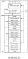
- FIG. 5 is a block diagram depicting an illustrative example of a pressure tolerant energy system with a dual-voltage power system, such as the pressure tolerant energy system 310 depicted in FIG. 3 .
- the pressure tolerant energy system 310 may include management circuitry 412, communication network 410, backplane 408, electrical connections 406, tray 404, primary battery module 502, and parasitic battery module 504.
- Other components illustrated by pressure tolerant energy system 310 in FIG. 4 have been omitted for ease of explanation.
- the primary battery module 502 may operate at a voltage suitable for providing power to primary systems.
- the nominal operating voltage of the primary battery module 502 may be 300 V.
- the primary battery module 502 may comprise multiple battery cells 402 as shown in FIG. 4 .
- the parasitic battery module 504 may operate at a voltage suitable for providing power to parasitic systems.
- the nominal operating voltage of the parasitic battery module 504 may be 30 V.
- the parasitic battery module 504 may comprise multiple battery cells 402 as shown in FIG. 4 . In some aspects, the parasitic battery module 504 may comprise one battery cell 402.
- the primary battery module 502 and parasitic battery module 504 may be placed into tray 404.
- the tray 404 may be made from any suitable material, such as thermoformed plastic.
- the tray 404 may provide structural support, alignment, and electrical insulation for the primary battery module 502 and parasitic battery module 504.
- the primary battery module 502 and parasitic battery module 504 may be placed into two separate trays in order to provide further electrical insulation due to the large difference in operating voltages between the primary battery module 502 and parasitic battery module 504. These separate trays may be stacked in either the same enclosure (as shown in FIG. 9 ), or in separate enclosures (as shown in FIGS. 7 and 8 ).
- the primary battery module 502 and parasitic battery module 504 may be connected directly to an energy distribution system (an electrical "bus"), perhaps by a junction box.
- the primary battery module 502 and parasitic battery module 504 may be connected to two different energy distribution networks. Each energy distribution system may distribute power to the primary systems and parasitic systems, respectively, either from within their own enclosure or via connections between the enclosures (as shown in FIG. 10 ),
- primary battery module 502 and parasitic battery module 504 may be directly connected to the management circuitry 412.
- the primary battery module 502 and parasitic battery module 504 may be connected to management circuitry 412 through communication network 410.
- Communication network 410 may be any suitable network for communicating control signals.
- the management circuitry 412 may comprise a pressure tolerant circuit board that may be manually programmed using any suitable programming language.
- the management circuitry 412 may manage the power delivered from the primary battery module 502 and the power delivered from the parasitic battery module 504.
- the management circuitry 412 may comprise two sub management circuitries in order to separately manage the power from the primary battery module 502 and the power delivered from the parasitic battery module 504.
- FIG. 6 is a block diagram of a battery module 600 including multiple battery cells 606, 608, 610, 612, 614, and 616 according to an illustrative aspect of the disclosure.
- the first plurality of battery cells 606-616 are arranged in series to provide a first or primary voltage output 602, e.g., 300V (between leads 602 and 622).
- At least one battery cell 616 may be configured to provide a secondary voltage output 604, e.g., 30 V (between leads 604 and 622), that is lower than the primary voltage output 602.
- the secondary voltage output 604 may be provided to some or all parasitic systems or components.
- the battery module 600 includes at least two battery cells 614 and 616 arranged to provide the secondary voltage.
- the voltage supply can be switched to a second battery cell 614 to provide the secondary voltage (between output leads 618 and 620) to the parasitic systems.
- the threshold voltage may be set at, for example, 25 volts or 20 volts.
- a processor such as central control unit 160, may monitor the secondary voltage output 604 and, in response to the voltage dropping below the threshold voltage, switch to battery cell 614 to provide the secondary voltage via leads 618 and 620,
- FIGS. 7A and 7B are block diagrams depicting exemplary AUVs 700, according to an illustrative aspect of the present disclosure.
- AUV 700 includes a 300V battery pack 702 that is used to deliver power to a thruster motor 706, inertial navigation system (INS) sensor 708, and motor controller 710.
- INS inertial navigation system
- a DC-DC converter 712 converts the 300 V output from the battery pack 702 into a 24 V input for the INS sensor 708 and motor controller 710.
- the conversion from 300 V to 24 V using the DC-DC converter 712 results in parasitic loss.
- the configuration as shown in FIG. 7B reduces parasitic losses by eliminating the need for down conversion of voltages.
- AUV 700 includes a 30 V battery pack 704 in addition to the 300 V battery pack 702 in separate enclosures.
- the 30 V battery pack 704 can be used to deliver power to the INS sensor 708 and motor controller 710.
- FIGS. 8A and 8B are block diagrams depicting exemplary AUVs 800, according to an illustrative aspect of the present disclosure. Similar to AUV 700, as shown in FIGS. 7A and 7B , AUV 800 includes a 300V battery pack 802 that is used to deliver power to a thruster motor 806, INS sensor 808, motor controller 810, and depth sensor 816. In this configuration, a DC-DC converter 812 converts the 300 V output from the battery pack 802 into a 24 V input for the INS sensor 808 and motor controller 810. In one aspect, AUV 800 includes an additional DC-DC converter 814 that converts the 24 V output from the DC-DC converter 812 into a 12 V input for the depth sensor 816.
- AUV 800 includes a 30 V battery pack 804 and a 12 V battery pack 818 in addition to the 300 V battery pack 802 in separate enclosures.
- the 30 V battery pack 804 can be used to deliver power to the INS sensor 708 and motor controller 710, and the 12 V battery pack 818 can be used to deliver power to the depth sensor 816.
- FIG. 9 is a block diagram depicting an exemplary AUV 900, according to an illustrative aspect of the present disclosure.
- AUV 900 is similar to AUV 700 and AUV 800, except that the batteries are in the same enclosure.
- AUV 900 includes a dual voltage battery pack 902 that delivers power to thruster motor 906, INS sensor 908, and motor controller 910.
- Dual voltage battery pack 902 includes battery managers 912 and a number of batteries 914 that can be connected in series to deliver power at 300 V to the thruster motor 906 or arranged such that one of the batteries can deliver power to the INS sensor 908 at 30 V and another battery can deliver power to the motor controller 910 at 30 V.
- this configuration reduces parasitic losses by eliminating the need for down conversion of voltages.
- FIGS. 10A and 10B are block diagrams depicting battery pack including multiple battery, according to an illustrative aspect of the present disclosure.
- FIG. 10A shows a 300 V battery pack 1000 that includes a battery manager 1004, a DC-DC converter 1006, and batteries 1008.
- the batteries 1008 can be connected in series to deliver a power output at 300 V.
- Each battery 1008 includes multiple battery cells and a microprocessor that requires a 3.3 V power source.
- the DC-DC converter 1006 converts the 300 V output of the series-connected batteries 1008 into a 3.3 V input for powering the microprocessors of each battery 1008.
- the down conversion from 300 V to 3.3 V results in parasitic losses. These parasitic losses can be reduced by using the configuration as shown in FIG. 10B.
- FIG. 10A shows a 300 V battery pack 1000 that includes a battery manager 1004, a DC-DC converter 1006, and batteries 1008.
- the batteries 1008 can be connected in series to deliver a power output at 300 V.
- the 10B shows a 300 V battery pack 1000 and a 30 V battery pack 1002.
- the 30 V battery pack can be arranged such that each battery 1008 delivers a 30 V power output.
- the 30 V power output can be down converted to 3.3 V using the DC-DC converter 1006 such that the 3.3 V power output can be used to deliver power to the microprocessors of the batteries 1008 of the 300 V battery pack and the 30 V battery pack.
Landscapes
- Engineering & Computer Science (AREA)
- Mechanical Engineering (AREA)
- Power Engineering (AREA)
- Aviation & Aerospace Engineering (AREA)
- Life Sciences & Earth Sciences (AREA)
- Sustainable Energy (AREA)
- Sustainable Development (AREA)
- Transportation (AREA)
- Secondary Cells (AREA)
- Charge And Discharge Circuits For Batteries Or The Like (AREA)
- Electric Propulsion And Braking For Vehicles (AREA)
- Battery Mounting, Suspending (AREA)
- Connection Of Batteries Or Terminals (AREA)
Applications Claiming Priority (2)
| Application Number | Priority Date | Filing Date | Title |
|---|---|---|---|
| US201762519282P | 2017-06-14 | 2017-06-14 | |
| PCT/US2018/037640 WO2018232183A1 (en) | 2017-06-14 | 2018-06-14 | Systems and methods for reducing parasitic power losses by an energy source |
Publications (3)
| Publication Number | Publication Date |
|---|---|
| EP3638534A1 EP3638534A1 (en) | 2020-04-22 |
| EP3638534A4 EP3638534A4 (en) | 2021-03-24 |
| EP3638534B1 true EP3638534B1 (en) | 2022-11-09 |
Family
ID=64656075
Family Applications (1)
| Application Number | Title | Priority Date | Filing Date |
|---|---|---|---|
| EP18818761.1A Active EP3638534B1 (en) | 2017-06-14 | 2018-06-14 | Systems and methods for reducing parasitic power losses by an energy source |
Country Status (6)
| Country | Link |
|---|---|
| US (1) | US10906410B2 (ja) |
| EP (1) | EP3638534B1 (ja) |
| JP (1) | JP7269892B2 (ja) |
| AU (1) | AU2018285542B2 (ja) |
| CA (1) | CA3067341A1 (ja) |
| WO (1) | WO2018232183A1 (ja) |
Families Citing this family (2)
| Publication number | Priority date | Publication date | Assignee | Title |
|---|---|---|---|---|
| US20190100306A1 (en) * | 2017-09-29 | 2019-04-04 | Intel IP Corporation | Propeller contact avoidance in an unmanned aerial vehicle |
| US11177520B2 (en) | 2018-07-02 | 2021-11-16 | Joulecase LLC | Modular battery pack system with multi-voltage bus |
Family Cites Families (41)
| Publication number | Priority date | Publication date | Assignee | Title |
|---|---|---|---|---|
| JP2979939B2 (ja) * | 1993-12-27 | 1999-11-22 | 株式会社日立製作所 | 二次電池システムの運転方法 |
| US5874786A (en) * | 1997-03-20 | 1999-02-23 | Space Systems/Loral, Inc. | Quad spacecraft power bus systems |
| US6430692B1 (en) * | 1998-09-25 | 2002-08-06 | International Business Machines, Corporation | Series-parallel battery array conversion |
| US6140800A (en) | 1999-05-27 | 2000-10-31 | Peterson; William Anders | Autonomous battery equalization circuit |
| JP2001136735A (ja) | 1999-11-02 | 2001-05-18 | Toyota Autom Loom Works Ltd | 電力変換供給方法及び電力変換供給装置並びに車両 |
| JP2002247781A (ja) * | 2001-02-21 | 2002-08-30 | Yazaki Corp | 給電装置 |
| JP2002291154A (ja) | 2001-03-28 | 2002-10-04 | Sumitomo Electric Ind Ltd | 直流電源装置 |
| JP4340020B2 (ja) * | 2001-04-10 | 2009-10-07 | パナソニック株式会社 | 無人搬送車用二次電池の充電制御方法 |
| JP4244531B2 (ja) | 2001-05-11 | 2009-03-25 | 株式会社デンソー | 複数電圧出力型車両用電源装置の制御方法 |
| AU2002333556A1 (en) * | 2001-09-10 | 2003-03-24 | Johnson Controls Technology Company | Energy management system for vehicle |
| EP1581406A2 (en) * | 2003-01-06 | 2005-10-05 | Johnson Controls Technology Company | Battery management system |
| JP2004338577A (ja) * | 2003-05-16 | 2004-12-02 | Hitachi Ltd | 車両用電力供給装置及び電力供給方法 |
| WO2007086472A1 (ja) * | 2006-01-27 | 2007-08-02 | Sharp Kabushiki Kaisha | 電力供給システム |
| JP4258534B2 (ja) * | 2006-07-18 | 2009-04-30 | トヨタ自動車株式会社 | 電源システム |
| JP4447625B2 (ja) * | 2007-06-25 | 2010-04-07 | 矢崎総業株式会社 | 電源装置 |
| JP5088557B2 (ja) | 2008-01-18 | 2012-12-05 | 本田技研工業株式会社 | 蓄電器及び電池システム |
| US8143851B2 (en) * | 2008-02-15 | 2012-03-27 | Apple Inc. | Power source having a parallel cell topology |
| JP2009247145A (ja) | 2008-03-31 | 2009-10-22 | Japan Aerospace Exploration Agency | 電源システム |
| TWI361975B (en) * | 2008-09-03 | 2012-04-11 | Inventec Corp | Multi-output voltage battery module and electronic device using the same |
| US8058743B2 (en) * | 2008-09-30 | 2011-11-15 | GM Global Technology Operations LLC | Automotive electrical system for coupling power converters with a transformer |
| US20100121511A1 (en) * | 2008-10-07 | 2010-05-13 | Boston-Power, Inc. | Li-ion battery array for vehicle and other large capacity applications |
| JP5406574B2 (ja) * | 2008-12-17 | 2014-02-05 | ソニーモバイルコミュニケーションズ株式会社 | 電源装置および電子機器 |
| US8362640B2 (en) * | 2009-07-15 | 2013-01-29 | Enfuse Systems, Inc. | System and method of controlling a plurality of energy loads and energy supplies in a coordinated manner |
| US9197143B1 (en) * | 2010-03-02 | 2015-11-24 | Lord Corporation | Harvesting power from multiple energy sources |
| JP5553385B2 (ja) * | 2010-09-02 | 2014-07-16 | オムロンオートモーティブエレクトロニクス株式会社 | 電源制御装置 |
| TW201214919A (en) * | 2010-09-24 | 2012-04-01 | Lite On Clean Energy Technology Corp | Hybrid battery module and battery management method |
| DE102011002452A1 (de) * | 2011-01-05 | 2012-07-05 | Sb Limotive Company Ltd. | Batterie mit autonomem Cell-Balancing |
| EP2705382B1 (en) | 2011-05-06 | 2017-04-12 | Hadal, Inc. | Systems and methods for synthetic aperture sonar |
| US9479009B2 (en) * | 2011-09-16 | 2016-10-25 | Zippy Technology Corp. | Power system for actively maintaining operation |
| US20130082639A1 (en) * | 2011-10-04 | 2013-04-04 | GM Global Technology Operations LLC | Electrical system having a primary energy source and a redundant rechargeable energy source |
| CN103066633B (zh) * | 2011-10-18 | 2015-11-18 | 丁景信 | 电源管理系统 |
| JP5488578B2 (ja) * | 2011-12-19 | 2014-05-14 | 株式会社デンソー | 車両用電動冷凍サイクル装置 |
| JP5461602B2 (ja) * | 2012-02-20 | 2014-04-02 | 三菱重工業株式会社 | 電力管理システム |
| KR101438610B1 (ko) * | 2012-12-28 | 2014-09-15 | 현대자동차 주식회사 | 충전기 및 그 구동 방법 |
| GB2520556B (en) * | 2013-11-26 | 2016-05-25 | Ford Global Tech Llc | A method of controlling a mild hybrid electric vehicle |
| US9457684B2 (en) | 2014-03-26 | 2016-10-04 | Ford Global Technologies, Llc | Redundant electrical power for autonomous vehicles |
| CN105981258A (zh) * | 2014-08-08 | 2016-09-28 | 深圳市大疆创新科技有限公司 | 用于无人飞行器电池能源备用的系统及方法 |
| FR3026384B1 (fr) | 2014-09-29 | 2021-05-14 | Dcns | Engin sous-marin muni d'un reseau d'alimentation multiniveaux |
| DE102015106773A1 (de) * | 2015-04-30 | 2016-11-03 | Dr. Ing. H.C. F. Porsche Aktiengesellschaft | Batteriesystem mit Batteriesteuerung |
| JP6599653B2 (ja) * | 2015-06-16 | 2019-10-30 | 矢崎総業株式会社 | 電源分配システム |
| JP6593362B2 (ja) * | 2017-01-31 | 2019-10-23 | トヨタ自動車株式会社 | 電源システム |
-
2018
- 2018-06-14 AU AU2018285542A patent/AU2018285542B2/en active Active
- 2018-06-14 EP EP18818761.1A patent/EP3638534B1/en active Active
- 2018-06-14 WO PCT/US2018/037640 patent/WO2018232183A1/en unknown
- 2018-06-14 CA CA3067341A patent/CA3067341A1/en active Pending
- 2018-06-14 US US16/009,100 patent/US10906410B2/en active Active
- 2018-06-14 JP JP2019569413A patent/JP7269892B2/ja active Active
Also Published As
| Publication number | Publication date |
|---|---|
| EP3638534A1 (en) | 2020-04-22 |
| US10906410B2 (en) | 2021-02-02 |
| EP3638534A4 (en) | 2021-03-24 |
| JP7269892B2 (ja) | 2023-05-09 |
| AU2018285542B2 (en) | 2023-12-21 |
| US20180361873A1 (en) | 2018-12-20 |
| CA3067341A1 (en) | 2018-12-20 |
| JP2020523975A (ja) | 2020-08-06 |
| WO2018232183A1 (en) | 2018-12-20 |
| AU2018285542A1 (en) | 2020-02-13 |
Similar Documents
| Publication | Publication Date | Title |
|---|---|---|
| EP3639348B1 (en) | Systems and methods for configurable battery charging | |
| US10000260B2 (en) | Systems and methods for pressure tolerant energy systems | |
| US11312463B2 (en) | Systems and methods for retractable marine power generation | |
| US9630517B2 (en) | Unmanned aerial vehicle, charging station, and automatic charging system for unmanned aerial vehicle including the same | |
| EP3638534B1 (en) | Systems and methods for reducing parasitic power losses by an energy source | |
| Pyle et al. | Leveraging a large UUV platform with a docking station to enable forward basing and persistence for light weight AUVs | |
| US20190326764A1 (en) | Hybrid energy storage system with multiple energy and power densities | |
| US7194975B2 (en) | Unmanned underwater vehicle health monitoring system and method | |
| Deutsch et al. | Design of an AUV research platform for demonstration of novel technologies | |
| US10763685B1 (en) | System and methods for regulating charging rate based on environmental conditions | |
| US10978889B1 (en) | System and methods for multi-level battery protection | |
| WO2020035042A1 (zh) | 飞行器的供电方法、装置、飞行控制系统及飞行器 | |
| Woolsey et al. | Integration of pressure-tolerant lithium ion battery modules within the Mola Mola AUV | |
| KR102289849B1 (ko) | 무인 비행체 및 그의 운용 방법 | |
| Djapic et al. | Heterogeneous Autonomous Mobile Maritime Expeditionary Robots |
Legal Events
| Date | Code | Title | Description |
|---|---|---|---|
| STAA | Information on the status of an ep patent application or granted ep patent |
Free format text: STATUS: THE INTERNATIONAL PUBLICATION HAS BEEN MADE |
|
| PUAI | Public reference made under article 153(3) epc to a published international application that has entered the european phase |
Free format text: ORIGINAL CODE: 0009012 |
|
| STAA | Information on the status of an ep patent application or granted ep patent |
Free format text: STATUS: REQUEST FOR EXAMINATION WAS MADE |
|
| 17P | Request for examination filed |
Effective date: 20200110 |
|
| AK | Designated contracting states |
Kind code of ref document: A1 Designated state(s): AL AT BE BG CH CY CZ DE DK EE ES FI FR GB GR HR HU IE IS IT LI LT LU LV MC MK MT NL NO PL PT RO RS SE SI SK SM TR |
|
| AX | Request for extension of the european patent |
Extension state: BA ME |
|
| DAV | Request for validation of the european patent (deleted) | ||
| DAX | Request for extension of the european patent (deleted) | ||
| A4 | Supplementary search report drawn up and despatched |
Effective date: 20210222 |
|
| RIC1 | Information provided on ipc code assigned before grant |
Ipc: H02J 1/08 20060101ALI20210216BHEP Ipc: B63G 8/00 20060101ALI20210216BHEP Ipc: B60L 50/60 20190101AFI20210216BHEP |
|
| RIC1 | Information provided on ipc code assigned before grant |
Ipc: B60L 53/00 20190101ALN20220314BHEP Ipc: H02J 7/00 20060101ALI20220314BHEP Ipc: H02J 1/08 20060101ALI20220314BHEP Ipc: B63G 8/00 20060101ALI20220314BHEP Ipc: B60L 50/60 20190101AFI20220314BHEP |
|
| REG | Reference to a national code |
Ref country code: DE Ref legal event code: R079 Ref document number: 602018042939 Country of ref document: DE Free format text: PREVIOUS MAIN CLASS: B60L0011180000 Ipc: B60L0050600000 |
|
| GRAP | Despatch of communication of intention to grant a patent |
Free format text: ORIGINAL CODE: EPIDOSNIGR1 |
|
| STAA | Information on the status of an ep patent application or granted ep patent |
Free format text: STATUS: GRANT OF PATENT IS INTENDED |
|
| RIC1 | Information provided on ipc code assigned before grant |
Ipc: B60L 53/00 20190101ALN20220426BHEP Ipc: H02J 7/00 20060101ALI20220426BHEP Ipc: H02J 1/08 20060101ALI20220426BHEP Ipc: B63G 8/00 20060101ALI20220426BHEP Ipc: B60L 50/60 20190101AFI20220426BHEP |
|
| INTG | Intention to grant announced |
Effective date: 20220530 |
|
| GRAS | Grant fee paid |
Free format text: ORIGINAL CODE: EPIDOSNIGR3 |
|
| GRAA | (expected) grant |
Free format text: ORIGINAL CODE: 0009210 |
|
| STAA | Information on the status of an ep patent application or granted ep patent |
Free format text: STATUS: THE PATENT HAS BEEN GRANTED |
|
| AK | Designated contracting states |
Kind code of ref document: B1 Designated state(s): AL AT BE BG CH CY CZ DE DK EE ES FI FR GB GR HR HU IE IS IT LI LT LU LV MC MK MT NL NO PL PT RO RS SE SI SK SM TR |
|
| REG | Reference to a national code |
Ref country code: GB Ref legal event code: FG4D |
|
| REG | Reference to a national code |
Ref country code: CH Ref legal event code: EP Ref country code: AT Ref legal event code: REF Ref document number: 1530139 Country of ref document: AT Kind code of ref document: T Effective date: 20221115 |
|
| REG | Reference to a national code |
Ref country code: DE Ref legal event code: R096 Ref document number: 602018042939 Country of ref document: DE |
|
| REG | Reference to a national code |
Ref country code: IE Ref legal event code: FG4D |
|
| REG | Reference to a national code |
Ref country code: NO Ref legal event code: T2 Effective date: 20221109 |
|
| REG | Reference to a national code |
Ref country code: LT Ref legal event code: MG9D |
|
| REG | Reference to a national code |
Ref country code: NL Ref legal event code: MP Effective date: 20221109 |
|
| REG | Reference to a national code |
Ref country code: AT Ref legal event code: MK05 Ref document number: 1530139 Country of ref document: AT Kind code of ref document: T Effective date: 20221109 |
|
| PG25 | Lapsed in a contracting state [announced via postgrant information from national office to epo] |
Ref country code: SE Free format text: LAPSE BECAUSE OF FAILURE TO SUBMIT A TRANSLATION OF THE DESCRIPTION OR TO PAY THE FEE WITHIN THE PRESCRIBED TIME-LIMIT Effective date: 20221109 Ref country code: PT Free format text: LAPSE BECAUSE OF FAILURE TO SUBMIT A TRANSLATION OF THE DESCRIPTION OR TO PAY THE FEE WITHIN THE PRESCRIBED TIME-LIMIT Effective date: 20230309 Ref country code: LT Free format text: LAPSE BECAUSE OF FAILURE TO SUBMIT A TRANSLATION OF THE DESCRIPTION OR TO PAY THE FEE WITHIN THE PRESCRIBED TIME-LIMIT Effective date: 20221109 Ref country code: FI Free format text: LAPSE BECAUSE OF FAILURE TO SUBMIT A TRANSLATION OF THE DESCRIPTION OR TO PAY THE FEE WITHIN THE PRESCRIBED TIME-LIMIT Effective date: 20221109 Ref country code: ES Free format text: LAPSE BECAUSE OF FAILURE TO SUBMIT A TRANSLATION OF THE DESCRIPTION OR TO PAY THE FEE WITHIN THE PRESCRIBED TIME-LIMIT Effective date: 20221109 Ref country code: AT Free format text: LAPSE BECAUSE OF FAILURE TO SUBMIT A TRANSLATION OF THE DESCRIPTION OR TO PAY THE FEE WITHIN THE PRESCRIBED TIME-LIMIT Effective date: 20221109 |
|
| PG25 | Lapsed in a contracting state [announced via postgrant information from national office to epo] |
Ref country code: RS Free format text: LAPSE BECAUSE OF FAILURE TO SUBMIT A TRANSLATION OF THE DESCRIPTION OR TO PAY THE FEE WITHIN THE PRESCRIBED TIME-LIMIT Effective date: 20221109 Ref country code: PL Free format text: LAPSE BECAUSE OF FAILURE TO SUBMIT A TRANSLATION OF THE DESCRIPTION OR TO PAY THE FEE WITHIN THE PRESCRIBED TIME-LIMIT Effective date: 20221109 Ref country code: LV Free format text: LAPSE BECAUSE OF FAILURE TO SUBMIT A TRANSLATION OF THE DESCRIPTION OR TO PAY THE FEE WITHIN THE PRESCRIBED TIME-LIMIT Effective date: 20221109 Ref country code: IS Free format text: LAPSE BECAUSE OF FAILURE TO SUBMIT A TRANSLATION OF THE DESCRIPTION OR TO PAY THE FEE WITHIN THE PRESCRIBED TIME-LIMIT Effective date: 20230309 Ref country code: HR Free format text: LAPSE BECAUSE OF FAILURE TO SUBMIT A TRANSLATION OF THE DESCRIPTION OR TO PAY THE FEE WITHIN THE PRESCRIBED TIME-LIMIT Effective date: 20221109 Ref country code: GR Free format text: LAPSE BECAUSE OF FAILURE TO SUBMIT A TRANSLATION OF THE DESCRIPTION OR TO PAY THE FEE WITHIN THE PRESCRIBED TIME-LIMIT Effective date: 20230210 |
|
| PG25 | Lapsed in a contracting state [announced via postgrant information from national office to epo] |
Ref country code: NL Free format text: LAPSE BECAUSE OF FAILURE TO SUBMIT A TRANSLATION OF THE DESCRIPTION OR TO PAY THE FEE WITHIN THE PRESCRIBED TIME-LIMIT Effective date: 20221109 |
|
| PG25 | Lapsed in a contracting state [announced via postgrant information from national office to epo] |
Ref country code: SM Free format text: LAPSE BECAUSE OF FAILURE TO SUBMIT A TRANSLATION OF THE DESCRIPTION OR TO PAY THE FEE WITHIN THE PRESCRIBED TIME-LIMIT Effective date: 20221109 Ref country code: RO Free format text: LAPSE BECAUSE OF FAILURE TO SUBMIT A TRANSLATION OF THE DESCRIPTION OR TO PAY THE FEE WITHIN THE PRESCRIBED TIME-LIMIT Effective date: 20221109 Ref country code: EE Free format text: LAPSE BECAUSE OF FAILURE TO SUBMIT A TRANSLATION OF THE DESCRIPTION OR TO PAY THE FEE WITHIN THE PRESCRIBED TIME-LIMIT Effective date: 20221109 Ref country code: DK Free format text: LAPSE BECAUSE OF FAILURE TO SUBMIT A TRANSLATION OF THE DESCRIPTION OR TO PAY THE FEE WITHIN THE PRESCRIBED TIME-LIMIT Effective date: 20221109 Ref country code: CZ Free format text: LAPSE BECAUSE OF FAILURE TO SUBMIT A TRANSLATION OF THE DESCRIPTION OR TO PAY THE FEE WITHIN THE PRESCRIBED TIME-LIMIT Effective date: 20221109 |
|
| PGFP | Annual fee paid to national office [announced via postgrant information from national office to epo] |
Ref country code: NO Payment date: 20230628 Year of fee payment: 6 Ref country code: FR Payment date: 20230626 Year of fee payment: 6 Ref country code: DE Payment date: 20230626 Year of fee payment: 6 |
|
| REG | Reference to a national code |
Ref country code: DE Ref legal event code: R097 Ref document number: 602018042939 Country of ref document: DE |
|
| PG25 | Lapsed in a contracting state [announced via postgrant information from national office to epo] |
Ref country code: SK Free format text: LAPSE BECAUSE OF FAILURE TO SUBMIT A TRANSLATION OF THE DESCRIPTION OR TO PAY THE FEE WITHIN THE PRESCRIBED TIME-LIMIT Effective date: 20221109 Ref country code: AL Free format text: LAPSE BECAUSE OF FAILURE TO SUBMIT A TRANSLATION OF THE DESCRIPTION OR TO PAY THE FEE WITHIN THE PRESCRIBED TIME-LIMIT Effective date: 20221109 |
|
| PLBE | No opposition filed within time limit |
Free format text: ORIGINAL CODE: 0009261 |
|
| STAA | Information on the status of an ep patent application or granted ep patent |
Free format text: STATUS: NO OPPOSITION FILED WITHIN TIME LIMIT |
|
| 26N | No opposition filed |
Effective date: 20230810 |
|
| PGFP | Annual fee paid to national office [announced via postgrant information from national office to epo] |
Ref country code: GB Payment date: 20230627 Year of fee payment: 6 |
|
| PG25 | Lapsed in a contracting state [announced via postgrant information from national office to epo] |
Ref country code: SI Free format text: LAPSE BECAUSE OF FAILURE TO SUBMIT A TRANSLATION OF THE DESCRIPTION OR TO PAY THE FEE WITHIN THE PRESCRIBED TIME-LIMIT Effective date: 20221109 |
|
| PG25 | Lapsed in a contracting state [announced via postgrant information from national office to epo] |
Ref country code: MC Free format text: LAPSE BECAUSE OF FAILURE TO SUBMIT A TRANSLATION OF THE DESCRIPTION OR TO PAY THE FEE WITHIN THE PRESCRIBED TIME-LIMIT Effective date: 20221109 |
|
| PG25 | Lapsed in a contracting state [announced via postgrant information from national office to epo] |
Ref country code: MC Free format text: LAPSE BECAUSE OF FAILURE TO SUBMIT A TRANSLATION OF THE DESCRIPTION OR TO PAY THE FEE WITHIN THE PRESCRIBED TIME-LIMIT Effective date: 20221109 |
|
| REG | Reference to a national code |
Ref country code: CH Ref legal event code: PL |
|
| REG | Reference to a national code |
Ref country code: BE Ref legal event code: MM Effective date: 20230630 |
|
| PG25 | Lapsed in a contracting state [announced via postgrant information from national office to epo] |
Ref country code: LU Free format text: LAPSE BECAUSE OF NON-PAYMENT OF DUE FEES Effective date: 20230614 |
|
| REG | Reference to a national code |
Ref country code: IE Ref legal event code: MM4A |
|
| PG25 | Lapsed in a contracting state [announced via postgrant information from national office to epo] |
Ref country code: LU Free format text: LAPSE BECAUSE OF NON-PAYMENT OF DUE FEES Effective date: 20230614 |
|
| PG25 | Lapsed in a contracting state [announced via postgrant information from national office to epo] |
Ref country code: IE Free format text: LAPSE BECAUSE OF NON-PAYMENT OF DUE FEES Effective date: 20230614 |
|
| PG25 | Lapsed in a contracting state [announced via postgrant information from national office to epo] |
Ref country code: IE Free format text: LAPSE BECAUSE OF NON-PAYMENT OF DUE FEES Effective date: 20230614 Ref country code: CH Free format text: LAPSE BECAUSE OF NON-PAYMENT OF DUE FEES Effective date: 20230630 |