EP3636919B1 - Mobile dickstoffpumpe - Google Patents
Mobile dickstoffpumpe Download PDFInfo
- Publication number
- EP3636919B1 EP3636919B1 EP19202219.2A EP19202219A EP3636919B1 EP 3636919 B1 EP3636919 B1 EP 3636919B1 EP 19202219 A EP19202219 A EP 19202219A EP 3636919 B1 EP3636919 B1 EP 3636919B1
- Authority
- EP
- European Patent Office
- Prior art keywords
- cover
- thick
- chassis
- travel
- pump
- Prior art date
- Legal status (The legal status is an assumption and is not a legal conclusion. Google has not performed a legal analysis and makes no representation as to the accuracy of the status listed.)
- Active
Links
Images




Classifications
-
- F—MECHANICAL ENGINEERING; LIGHTING; HEATING; WEAPONS; BLASTING
- F04—POSITIVE - DISPLACEMENT MACHINES FOR LIQUIDS; PUMPS FOR LIQUIDS OR ELASTIC FLUIDS
- F04B—POSITIVE-DISPLACEMENT MACHINES FOR LIQUIDS; PUMPS
- F04B15/00—Pumps adapted to handle specific fluids, e.g. by selection of specific materials for pumps or pump parts
- F04B15/02—Pumps adapted to handle specific fluids, e.g. by selection of specific materials for pumps or pump parts the fluids being viscous or non-homogeneous
-
- B—PERFORMING OPERATIONS; TRANSPORTING
- B60—VEHICLES IN GENERAL
- B60Q—ARRANGEMENT OF SIGNALLING OR LIGHTING DEVICES, THE MOUNTING OR SUPPORTING THEREOF OR CIRCUITS THEREFOR, FOR VEHICLES IN GENERAL
- B60Q1/00—Arrangement of optical signalling or lighting devices, the mounting or supporting thereof or circuits therefor
- B60Q1/26—Arrangement of optical signalling or lighting devices, the mounting or supporting thereof or circuits therefor the devices being primarily intended to indicate the vehicle, or parts thereof, or to give signals, to other traffic
- B60Q1/2615—Arrangement of optical signalling or lighting devices, the mounting or supporting thereof or circuits therefor the devices being primarily intended to indicate the vehicle, or parts thereof, or to give signals, to other traffic mounted on the vehicle body, e.g. with magnets
-
- B—PERFORMING OPERATIONS; TRANSPORTING
- B60—VEHICLES IN GENERAL
- B60Q—ARRANGEMENT OF SIGNALLING OR LIGHTING DEVICES, THE MOUNTING OR SUPPORTING THEREOF OR CIRCUITS THEREFOR, FOR VEHICLES IN GENERAL
- B60Q1/00—Arrangement of optical signalling or lighting devices, the mounting or supporting thereof or circuits therefor
- B60Q1/26—Arrangement of optical signalling or lighting devices, the mounting or supporting thereof or circuits therefor the devices being primarily intended to indicate the vehicle, or parts thereof, or to give signals, to other traffic
- B60Q1/2661—Arrangement of optical signalling or lighting devices, the mounting or supporting thereof or circuits therefor the devices being primarily intended to indicate the vehicle, or parts thereof, or to give signals, to other traffic mounted on parts having other functions
-
- B—PERFORMING OPERATIONS; TRANSPORTING
- B60—VEHICLES IN GENERAL
- B60Q—ARRANGEMENT OF SIGNALLING OR LIGHTING DEVICES, THE MOUNTING OR SUPPORTING THEREOF OR CIRCUITS THEREFOR, FOR VEHICLES IN GENERAL
- B60Q1/00—Arrangement of optical signalling or lighting devices, the mounting or supporting thereof or circuits therefor
- B60Q1/26—Arrangement of optical signalling or lighting devices, the mounting or supporting thereof or circuits therefor the devices being primarily intended to indicate the vehicle, or parts thereof, or to give signals, to other traffic
- B60Q1/30—Arrangement of optical signalling or lighting devices, the mounting or supporting thereof or circuits therefor the devices being primarily intended to indicate the vehicle, or parts thereof, or to give signals, to other traffic for indicating rear of vehicle, e.g. by means of reflecting surfaces
- B60Q1/305—Indicating devices for towed vehicles
-
- B—PERFORMING OPERATIONS; TRANSPORTING
- B60—VEHICLES IN GENERAL
- B60Q—ARRANGEMENT OF SIGNALLING OR LIGHTING DEVICES, THE MOUNTING OR SUPPORTING THEREOF OR CIRCUITS THEREFOR, FOR VEHICLES IN GENERAL
- B60Q3/00—Arrangement of lighting devices for vehicle interiors; Lighting devices specially adapted for vehicle interiors
- B60Q3/30—Arrangement of lighting devices for vehicle interiors; Lighting devices specially adapted for vehicle interiors for compartments other than passenger or driving compartments, e.g. luggage or engine compartments
-
- F—MECHANICAL ENGINEERING; LIGHTING; HEATING; WEAPONS; BLASTING
- F04—POSITIVE - DISPLACEMENT MACHINES FOR LIQUIDS; PUMPS FOR LIQUIDS OR ELASTIC FLUIDS
- F04B—POSITIVE-DISPLACEMENT MACHINES FOR LIQUIDS; PUMPS
- F04B17/00—Pumps characterised by combination with, or adaptation to, specific driving engines or motors
- F04B17/06—Mobile combinations
-
- F—MECHANICAL ENGINEERING; LIGHTING; HEATING; WEAPONS; BLASTING
- F04—POSITIVE - DISPLACEMENT MACHINES FOR LIQUIDS; PUMPS FOR LIQUIDS OR ELASTIC FLUIDS
- F04B—POSITIVE-DISPLACEMENT MACHINES FOR LIQUIDS; PUMPS
- F04B39/00—Component parts, details, or accessories, of pumps or pumping systems specially adapted for elastic fluids, not otherwise provided for in, or of interest apart from, groups F04B25/00 - F04B37/00
-
- F—MECHANICAL ENGINEERING; LIGHTING; HEATING; WEAPONS; BLASTING
- F04—POSITIVE - DISPLACEMENT MACHINES FOR LIQUIDS; PUMPS FOR LIQUIDS OR ELASTIC FLUIDS
- F04B—POSITIVE-DISPLACEMENT MACHINES FOR LIQUIDS; PUMPS
- F04B53/00—Component parts, details or accessories not provided for in, or of interest apart from, groups F04B1/00 - F04B23/00 or F04B39/00 - F04B47/00
- F04B53/16—Casings; Cylinders; Cylinder liners or heads; Fluid connections
-
- B—PERFORMING OPERATIONS; TRANSPORTING
- B60—VEHICLES IN GENERAL
- B60Q—ARRANGEMENT OF SIGNALLING OR LIGHTING DEVICES, THE MOUNTING OR SUPPORTING THEREOF OR CIRCUITS THEREFOR, FOR VEHICLES IN GENERAL
- B60Q2800/00—Features related to particular types of vehicles not otherwise provided for
- B60Q2800/20—Utility vehicles, e.g. for agriculture, construction work
Definitions
- the invention relates to a mobile thick matter pump for conveying thick matter, with a chassis, a pump unit arranged on the chassis, a feed hopper open at the top for feeding in thick matter to be conveyed, a pivotable cover, the cover closing the upper filling opening of the feed hopper in a closed pivoting position and in an opening pivoting position, the filling opening of the hopper is released, and rear lighting.
- Slurry pumps known from the prior art have rear lights rigidly coupled to the chassis, which include, for example, a rear light that is permanently aligned in a specific position in relation to the chassis.
- the problem with the rigid rear light mounts known from the prior art is that they usually protrude from the contour of the chassis. In construction site operation, such brackets are susceptible to damage from collisions.
- Pivotable, foldable or adjustable devices are also known from the prior art in order to better protect the rear lights from collisions during construction site operation, while the rear lights are positioned as wide as possible or on the outside during road operation.
- Such a device is, for example, from DE 20 2016 007 988 U1 or from the accessories catalog PUMI ® 21-3
- a disadvantage of the solution described here is that the rear lighting is arranged below the feed hopper during construction site operation and is therefore in an area that is easily soiled when thick material to be conveyed is fed in. In addition, the rear lighting is still in an area during construction site operation where damage can easily occur when truck mixers drive up to the feed hopper. The rear lighting is easily damaged or soiled when thick material to be conveyed, in particular concrete, is fed in and also gets in the way, which can also lead to collisions.
- damage to and contamination of the rear lighting should be avoided when feeding thick matter to be conveyed into the feed hopper via its upper filling opening.
- the rear lighting is arranged on the pivotable cover and is designed to be pivotable together with the cover, a safe arrangement of the rear lighting can be made possible in a simple manner when feeding thick matter to be conveyed into the feed hopper.
- the rear lighting on the pivotable cover is pivoted together with this.
- the rear lighting on the construction site does not get in the way of the thick matter pump during pumping operation while the thick matter to be conveyed is being fed into the feed hopper.
- the rear lighting In the opening pivoting position of the cover, the rear lighting is pivoted with it so that it does not go through Thick stock is contaminated when it is fed into the feed hopper.
- a secure position for the rear lights can be set particularly easily by pivoting the rear lights together with the pivotable cover.
- the rear lighting is preferably formed by two red reflectors. Furthermore, the rear lighting preferably includes two direction indicators, which are further preferably designed as yellow flashing lights. In addition, the rear lighting can include two red tail lights that signal the end of the vehicle. In addition, the rear lights can have two brake lights that indicate braking of the vehicle. In addition, reversing lights, rear fog lights and a license plate light can be included in the rear light.
- the rear lighting is aligned in the closed pivoting position of the cover against the direction of travel of the chassis.
- the cover is pivoted in the area of its edge on the direction of travel, so that it can be moved from the closed pivoted position, in which the cover is aligned essentially horizontally, into the open pivoted position, in which the cover is aligned substantially vertically, is pivoted upwards in the direction of travel.
- the rear lighting can be easily brought into a position in front above the hopper, where the rear lighting is safe from dirt and damage during the feeding of thick matter to be conveyed into the hopper.
- a particularly advantageous embodiment of the invention relates to the rear light being attached to the cover via an auxiliary frame.
- the rear lights With the attachment of the rear lights via the subframe, the rear lights can be arranged independently of the shape of the cover. In this way, legal requirements for the arrangement of the rear lighting can be implemented easily and independently of the design of the cover and the hopper.
- a particularly advantageous embodiment of the invention provides that the subframe extends beyond the width of the cover transversely to the direction of travel of the chassis and the rear lighting is arranged at least partially offset in the direction of travel of the chassis next to the cover on the subframe.
- the rear lights may be necessary to arrange the rear lights partially in the direction of travel of the chassis on the side next to the cover on the frame in order to comply with the legal maximum distance from, for example, the direction indicator and tail light to the outside of the vehicle. In this way, parts of the rear lighting can be very easily arranged laterally next to this in the direction of travel, independently of the shape of the cover and the discharge funnel.
- An advantageous embodiment of the invention provides that a work lamp is arranged on the cover, which illuminates the feed hopper from above when the cover is in the open pivot position.
- a work lamp is arranged on the cover, which illuminates the feed hopper from above when the cover is in the open pivot position.
- a sludge pump according to the invention is shown.
- the sludge pump 1 has a chassis 2 of a trailer.
- a pump unit 3 is arranged on this chassis 2 .
- This pump unit 3 is supplied with thick matter to be conveyed via a feed hopper 4 which is arranged on the rear of the chassis 2 .
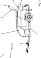
- the feed hopper 4 arranged on the rear of the chassis 2 has a pivotable cover 5 with which an upper filling opening of the feed hopper 4 can be closed in a closed pivot position, as shown in FIG figure 1 to see. In an opening pivot position, which in figure 2 is shown, the filling opening of the feed hopper 4 can be released from the cover 5 for the task of conveying thick matter.
- the sludge pump 1 has rear lighting 6 arranged at the rear.
- This rear lighting 6 is arranged according to the invention on the pivotable cover 5 and is shown in FIG figure 2 seen pivoted together with the cover 5.
- the rear light 6 is thus in the locked pivoted position of the cover 5 according to FIG figure 1 in an orientation opposite to the direction of travel indicated by the block arrow 30. With this Alignment against the direction of travel 30 of the chassis 2, the rear lights 6 are clearly visible to following road users.
- the figure 2 shows the sludge pump 1 according to FIG figure 1 ,
- the lid 5 is pivoted in the open pivot position forwards and upwards.
- the rear light 6 pivoted with the cover 5 is located above the feed hopper 4. This makes it easy to avoid contamination of the rear light 6 when thick matter to be conveyed is fed into the feed hopper 4.
- FIG 3 12 is a rear view of the sludge pump 1 of FIGS figures 1 and 2 to see.
- the rear lights 6 arranged on the pivotable cover 5 include two direction indicators, two tail lights, two brake lights and reversing lights, rear fog lights and a license plate light.
- the hopper 4 is approximately off-center, ie offset to the right when viewed from behind, and the pivotable cover 5 is slightly wider than the hopper and at the same time covers a document container 9 when the cover 5 is closed, as can be seen from FIGS figures 1 and 2 is evident.
- these rear lights 6 are preferably attached to an auxiliary frame, brackets or the like, not shown, which is arranged on the cover 5, or the entire cover 5 is made correspondingly wider, in particular wider than the feed hopper 4, to comply with the regulations for the arrangement of the rear lights.
- two rear reflectors (retroreflectors) 8 are arranged on the rear of the sludge pump 1, which are not pivoted together with the cover 5. As a result, they are still easily visible even when the cover 5 is pivoted into the open pivot position.
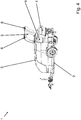
- the figure 5 shows a detailed view of the lid 5 in the opening pivot position.
- the view of the work light 7 arranged in the lid 5 is clear, which illuminates the feed hopper 4, its upper filling opening, and the area around the feed hopper 4 at dusk and in the dark from above .
- the cover 5 is designed in such a way that the work light 7 is not arranged directly above the feed hopper 4 when the cover 5 is closed, but somewhat behind it. This prevents the work lamp 7 from being contaminated when the thick matter is pumped back, which preferably takes place when the cover 5 is closed. For this purpose, the cover 5 protrudes somewhat to the rear beyond the feed hopper 4 .
Landscapes
- Engineering & Computer Science (AREA)
- Mechanical Engineering (AREA)
- General Engineering & Computer Science (AREA)
- Lighting Device Outwards From Vehicle And Optical Signal (AREA)
- Filling Or Emptying Of Bunkers, Hoppers, And Tanks (AREA)
Description
- Die Erfindung betrifft eine mobile Dickstoffpumpe zur Förderung von Dickstoff, mit einem Fahrgestell, einer auf dem Fahrgestell angeordneten Pumpeinheit, einem oben offenen Aufgabetrichter zur Aufgabe von zu förderndem Dickstoff, einem verschwenkbaren Deckel, wobei der Deckel in einer Verschlussschwenkstellung die obere Einfüllöffnung des Aufgabetrichters verschließt und in einer Öffnungsschwenkstellung die Einfüllöffnung des Aufgabetrichters freigibt, und einer Heckbeleuchtung.
- Aus dem Stand der Technik sind beispielsweise aus
DE 29 47 680 A1 oder aus Mustang-Trailers A/s: "Min Amigo / Bilens nye ven", FDM's member magazine "Motor" 4/2015, 30. April 2015, Seite 47, Lastenanhänger bekannt. In letzterem Dokument ist zu erkennen, dass die Heckbeleuchtung des Anhängers zur Ermöglichung einer niedrigen Ladekante am Deckel des Anhängers angebracht ist. - Aus dem Stand der Technik bekannte Dickstoffpumpen weisen starr mit dem Fahrgestell gekoppelte Heckbeleuchtungen auf, welche beispielsweise ein dauerhaft in einer bestimmten Position in Bezug auf das Fahrgestell ausgerichtetes Rücklicht umfassen. Problematisch an den aus dem Stand der Technik bekannten, starren Rücklichthalterungen ist, dass diese meist aus der Kontur des Fahrgestells hervorstehen. Im Baustellenbetrieb sind derartige Halterungen anfällig für Beschädigungen durch Kollisionen.
- Aus dem Stand der Technik sind auch schwenkbare, klappbare bzw. verstellbare Vorrichtungen bekannt, um die Heckbeleuchtungen im Baustellenbetrieb besser vor Kollisionen zu schützen, während die Heckbeleuchtungen im Straßenbetrieb möglichst breit bzw. außen positioniert werden. Eine solche Vorrichtung ist beispielsweise aus der
DE 20 2016 007 988 U1 oder aus dem Zubehörkatalog PUMI® 21-3 | 25-4 | 28-4 von 2016, Seiten 1-31 bekannt. Nachteilig an der hier beschrieben Lösung ist, dass die Heckbeleuchtung im Baustellenbetrieb unterhalb des Aufgabetrichters angeordnet ist und damit in einem Bereich, der bei Aufgabe von zu förderndem Dickstoff leicht verschmutzt. Außerdem befindet sich die Heckbeleuchtung im Baustellenbetrieb weiterhin in einem Bereich, in dem leicht Beschädigungen beim Heranfahren von Fahrmischern an den Aufgabetrichter entstehen können. So wird die Heckbeleuchtung bei Aufgabe von zu förderndem Dickstoff, insbesondere Beton, leicht beschädigt bzw. verunreinigt und steht ferner im Weg, was weiterhin zu Kollisionen führen kann. - Es ist daher Aufgabe der Erfindung, eine verbesserte Dickstoffpumpe anzugeben, die eine einfache und sichere Anordnung der Heckbeleuchtung im Baustellenbetrieb ermöglicht. Insbesondere sollen Beschädigungen und Verunreinigungen der Heckbeleuchtung bei Aufgabe von zu förderndem Dickstoff in den Aufgabetrichter über dessen obere Einfüllöffnung vermieden werden.
- Gelöst wird diese Aufgabe durch eine Dickstoffpumpe mit den Merkmalen des Anspruchs 1.
- Dadurch, dass die Heckbeleuchtung an dem verschwenkbaren Deckel angeordnet ist und zusammen mit dem Deckel verschwenkbar ausgebildet ist, kann auf einfache Weise eine sichere Anordnung der Heckbeleuchtung bei Aufgabe von zu förderndem Dickstoff in den Aufgabetrichter ermöglicht werden. Hierzu wird die Heckbeleuchtung an dem verschwenkbaren Deckel mit diesem zusammen verschwenkt. So ist die Heckbeleuchtung auf der Baustelle im Pumpbetrieb der Dickstoffpumpe während der Aufgabe von zu förderndem Dickstoff in den Aufgabetrichter nicht im Weg. In Öffnungsschwenkstellung des Deckels wird die Heckbeleuchtung mit verschwenkt, so dass sie nicht durch Dickstoff bei der Aufgabe in den Aufgabetrichter verschmutzt wird. Über die Verschwenkung der Heckbeleuchtung zusammen mit dem verschwenkbaren Deckel ist besonders einfach eine sichere Position für die Heckbeleuchtung einstellbar.
- Die Heckbeleuchtung wird vorzugsweise durch zwei rote Rückstrahler gebildet. Weiterhin umfasst die Heckbeleuchtung vorzugsweise zwei Fahrtrichtungsanzeiger, die weiter vorzugsweise als gelbe Blinkleuchten ausgebildet sind. Zudem kann die Heckbeleuchtung zwei rote Schlussleuchten umfassen, die das Ende des Fahrzeugs signalisieren. Außerdem kann die Heckbeleuchtung zwei Bremsleuchten aufweisen, die eine Bremsung des Fahrzeuges anzeigen. Außerdem können Rückfahrscheinwerfer, Nebelschlussleuchten und eine Kennzeichenbeleuchtung von der Heckbeleuchtung umfasst sein.
- Vorteilhafte Ausgestaltungen und Weiterbildungen der Erfindung ergeben sich aus den abhängigen Ansprüchen. Es ist darauf hinzuweisen, dass die in den Ansprüchen einzeln aufgeführten Merkmale auch in beliebiger und technologisch sinnvoller Weise miteinander kombiniert werden können und somit weitere Ausgestaltungen der Erfindung aufzeigen.
- Gemäß einer vorteilhaften Ausgestaltung der Erfindung ist vorgesehen, dass die Heckbeleuchtung in Verschlussschwenkstellung des Deckels entgegen der Fahrtrichtung des Fahrgestells ausgerichtet ist. Mit der Ausrichtung der Heckbeleuchtung in Verschlussschwenkstellung entgegen der Fahrtrichtung des Fahrgestells kann das Ende des Fahrgestells auch bei Dämmerung, Dunkelheit oder bei schlechten Witterungsverhältnissen von nachfolgenden Verkehrsteilnehmern sicher wahrgenommen werden. Die Ausrichtung der Heckbeleuchtung ist durch die Hauptabstrahlrichtung der die Heckbeleuchtung bildenden Leuchten gegeben, welche in Verschlussschwenkstellung des Deckels hauptsächlich entgegen der Fahrtrichtung des Fahrgestells leuchten.
- Besonders bevorzugt ist eine Ausführungsform, die vorsieht, dass der Deckel im Bereich seiner fahrtrichtungsseitigen Kante verschwenkbar angelenkt ist, so dass er aus der Verschlussschwenkstellung, in der der Deckel im Wesentlichen horizontal ausgerichtet ist, in die Öffnungsschwenkstellung, in der der Deckel im Wesentlichen vertikal ausgerichtet ist, in Fahrtrichtung nach oben verschwenkt wird. Mit der Öffnung des verschwenkbaren Deckels kann die Heckbeleuchtung einfach in eine Position vorne über dem Aufgabetrichter gebracht werden, wo die Heckbeleuchtung gegenüber Verschmutzungen und Beschädigungen während der Aufgabe von zu förderndem Dickstoff in den Aufgabetrichter sicher ist.
- Eine besonders vorteilhafte Ausführung der Erfindung bezieht sich darauf, dass die Heckbeleuchtung über einen Hilfsrahmen an dem Deckel befestigt ist. Mit der Befestigung der Heckbeleuchtung über den Hilfsrahmen kann die Anordnung der Heckbeleuchtung unabhängig von der Form des Deckels erfolgen. So lassen sich gesetzliche Vorgaben für die Anordnung der Heckbeleuchtung einfach und unabhängig von der Ausgestaltung des Deckels und des Aufgabetrichters realisieren.
- Eine besonders vorteilhafte Ausführung der Erfindung sieht vor, dass der Hilfsrahmen über die Breite des Deckels quer zur Fahrtrichtung des Fahrgestells hinausragt und die Heckbeleuchtung zumindest teilweise in Fahrtrichtung des Fahrgestells versetzt seitlich neben dem Deckel an dem Hilfsrahmen angeordnet ist. Bei besonders breiten Fahrzeugen, wie etwa Autobetonpumpen, kann es erforderlich sein, zur Einhaltung des gesetzlichen Maximalabstandes von beispielsweise Blinkleuchte und Schlussleuchte zur Außenseite des Fahrzeugs die Heckbeleuchtung teilweise in Fahrtrichtung des Fahrgestells seitlich neben dem Deckel an dem Rahmen anzuordnen. Auf diese Weise lassen sich Teile der Heckbeleuchtung sehr einfach unabhängig von der Form des Deckels und des Ausgabetrichters in Fahrtrichtung seitlich neben diesem anordnen.
- Eine vorteilhafte Ausführung der Erfindung sieht vor, dass an dem Deckel eine Arbeitsleuchte angeordnet ist, die in Öffnungsschwenkstellung des Deckels den Aufgabetrichter von oben beleuchtet. Mit einer solchen Arbeitsleuchte kann in Öffnungsschwenkstellung des Deckels der Aufgabetrichter, dessen obere Einfüllöffnung und der Bereich um den Aufgabetrichter ausreichend ausgeleuchtet werden, damit auch bei Dämmerung oder Dunkelheit eine sichere Arbeit möglich ist.
- Weitere Merkmale, Einzelheiten und Vorteile der Erfindung ergeben sich aufgrund der nachfolgenden Beschreibung sowie anhand der Zeichnungen, die Ausführungsbeispiele der Erfindung zeigen. Einander entsprechende Gegenstände oder Elemente sind in allen Figuren mit den gleichen Bezugszeichen versehen. Es zeigen:
- Figur 1
- erfindungsgemäße Dickstoffpumpe,
- Figur 2
- Dickstoffpumpe mit geöffnetem Deckel,
- Figur 3
- Rückansicht der Dickstoffpumpe,
- Figur 4
- Seitenansicht der Dickstoffpumpe und
- Figur 5
- Detailansicht zu Deckel
- Figur 6
- Seitenansicht des verschlossenen Deckels
- In der
Figur 1 mit dem Bezugszeichen 1 bezeichnet ist eine erfindungsgemäße Dickstoffpumpe dargestellt. Die Dickstoffpumpe 1 weist ein Fahrgestell 2 eines Anhängers auf. Auf diesem Fahrgestell 2 ist eine Pumpeinheit 3 angeordnet. Diese Pumpeinheit 3 wird mit zu förderndem Dickstoff über einen Aufgabetrichter 4 versorgt, der rückseitig am Fahrgestell 2 angeordnet ist. Der an der Rückseite des Fahrgestells 2 angeordnete Aufgabetrichter 4 verfügt über einen schwenkbaren Deckel 5, mit dem eine obere Einfüllöffnung des Aufgabetrichters 4 in einer Verschlussschwenkstellung verschlossen werden kann, wie inFigur 1 zu sehen. In einer Öffnungsschwenkstellung, welche inFigur 2 gezeigt ist, kann die Einfüllöffnung des Aufgabetrichters 4 von dem Deckel 5 für die Aufgabe von zu förderndem Dickstoff freigegeben werden. Die Dickstoffpumpe 1 verfügt über eine rückseitig angeordnete Heckbeleuchtung 6. Diese Heckbeleuchtung 6 ist erfindungsgemäß an dem verschwenkbaren Deckel 5 angeordnet und wird, wie ausFigur 2 ersichtlich, mit dem Deckel 5 zusammen verschwenkt. So befindet sich die Heckbeleuchtung 6 in Verschlussschwenkstellung des Deckels 5 gemäßFigur 1 in einer Ausrichtung entgegen der durch den Blockpfeil angedeuteten Fahrtrichtung 30. Mit dieser Ausrichtung entgegen der Fahrtrichtung 30 des Fahrgestells 2 ist die Heckbeleuchtung 6 für nachfolgende Verkehrsteilnehmer gut sichtbar. - Die
Figur 2 zeigt die Dickstoffpumpe 1 gemäßFigur 1 , wobei hier der Deckel 5 in Öffnungsschwenkstellung nach vorne oben verschwenkt ist. Die mit dem Deckel 5 verschwenkte Heckbeleuchtung 6 befindet sich in dieser Stellung oberhalb des Aufgabetrichters 4. Hierdurch lassen sich Verschmutzungen der Heckbeleuchtung 6 bei Aufgabe von zu förderndem Dickstoff in den Aufgabetrichter 4 einfach vermeiden. - Gemäß
Figur 3 ist eine Rückansicht der Dickstoffpumpe 1 aus denFiguren 1 und2 zu sehen. In dieser Darstellung gut zu erkennen ist, dass die an dem verschwenkbaren Deckel 5 angeordnete Heckbeleuchtung 6, zwei Fahrtrichtungsanzeiger, zwei Schlussleuchten, zwei Bremsleuchten sowie Rückfahrscheinwerfer, Nebelschlussleuchten und eine Kennzeichenbeleuchtung umfasst. Der Aufgabetrichter 4 liegt etwa außermittig, d.h. von hinten betrachtet nach rechts versetzt, und der verschwenkbare Deckel 5 ist etwas breiter als der Aufgabetrichter und deckt gleichzeitig einen Dokumentenbehälter 9 bei verschlossenem Deckel 5 ab, wie aus denFiguren 1 und2 ersichtlich ist. Bei breiteren Fragzeugen, wie etwa Autobetonpumpen, sind diese Leuchten der Heckbeleuchtung 6 vorzugsweise an einem nicht dargestellten Hilfsrahmen, Winkeln o.ä. befestigt, der an dem Deckel 5 angeordnet ist oder der gesamte Deckel 5 wird entsprechend breiter ausgeführt, insbesondere breiter als der Aufgabetrichter 4, um die Vorschriften für die Anordnung der Rückleuchten einzuhalten. Außerdem sind rückseitig an der Dickstoffpumpe 1 zwei Rückstrahler (Retroreflektoren) 8 angeordnet, die nicht zusammen mit dem Deckel 5 verschwenkt werden. Hierdurch sind diese auch bei Verschwenkung des Deckels 5 in Öffnungsschwenkstellung weiterhin gut sichtbar. - Die
Figur 5 stellt eine Detailansicht auf den Deckel 5 in Öffnungsschwenkstellung dar. In dieser Darstellung ist der Blick auf die im Deckel 5 angeordnete Arbeitsleuchte 7 frei, welche den Aufgabetrichter 4, dessen obere Einfüllöffnung, sowie den Bereich um den Aufgabetrichter 4 bei Dämmerung und Dunkelheit von oben beleuchtet. - Wie aus
Figur 6 ersichtlich, ist der Deckel 5 so ausgeführt, dass die Arbeitsleuchte 7 bei verschlossenem Deckel 5 nicht direkt über dem Aufgabetrichter 4 angeordnet ist, sondern etwas dahinter. Damit wird vermieden, dass die Arbeitsleuchte 7 beim Zurückpumpen des Dickstoffs, welches vorzugsweises bei verschlossenem Deckel 5 stattfindet, verunreinigt wird. Der Deckel 5 ragt dafür etwas nach hinten über den Aufgabetrichter 4 hinaus. -
- 1
- Mobile Dickstoffpumpe
- 2
- Fahrgestell
- 3
- Pumpeinheit
- 4
- Aufgabetrichter
- 5
- Deckel
- 6
- Heckbeleuchtung
- 7
- Arbeitsleuchte
- 8
- Rückstrahler
- 9
- Dokumentenbehälter
- 30
- Fahrtrichtung
Claims (6)
- Mobile Dickstoffpumpe (1) zur Förderung von Dickstoff, mit- einem Fahrgestell (2),- einer auf dem Fahrgestell (2) angeordneten Pumpeinheit (3),- einem oben offenen Aufgabetrichter (4) zur Aufgabe von zu förderndem Dickstoff,- einem verschwenkbaren Deckel (5), wobei der Deckel (5) in einer Verschlussschwenkstellung die obere Einfüllöffnung des Aufgabetrichters (4) verschließt und in einer Öffnungsschwenkstellung die Einfüllöffnung des Aufgabetrichters (4) freigibt, und- einer Heckbeleuchtung (6),dadurch gekennzeichnet,
dass die Heckbeleuchtung (6) an dem verschwenkbaren Deckel (5) angeordnet ist und zusammen mit dem Deckel (5) verschwenkbar ist. - Dickstoffpumpe (1) nach Anspruch 1, dadurch gekennzeichnet, dass die Heckbeleuchtung (6) in Verschlussschwenkstellung des Deckels (5) entgegen der Fahrtrichtung (30) des Fahrgestells (2) ausgerichtet ist.
- Dickstoffpumpe (1) nach Anspruch 1 oder 2, dadurch gekennzeichnet, dass der Deckel (5) im Bereich seiner fahrtrichtungsseitigen Kante verschwenkbar angelenkt ist, so dass er aus der Verschlussschwenkstellung, in der der Deckel (5) im Wesentlichen horizontal ausgerichtet ist, in die Öffnungsschwenkstellung, in der der Deckel (5) im Wesentlichen vertikal ausgerichtet ist, in Fahrtrichtung (30) nach oben verschwenkt wird.
- Dickstoffpumpe (1) nach einem der vorhergehenden Ansprüche, dadurch gekennzeichnet, dass die Heckbeleuchtung (6) über einen Hilfsrahmen an dem Deckel (5) befestigt ist.
- Dickstoffpumpe (1) nach Anspruch 4, dadurch gekennzeichnet, dass der Hilfsrahmen über die Breite des Deckels (5) quer zur Fahrtrichtung (30) des Fahrgestells (2) hinausragt und die Heckbeleuchtung (6) zumindest teilweise in Fahrtrichtung (30) des Fahrgestells (2) versetzt seitlich neben dem Deckel (5) an dem Hilfsrahmen angeordnet ist.
- Dickstoffpumpe (1) nach einem der vorhergehenden Ansprüche, dadurch gekennzeichnet, dass an dem Deckel (5) eine Arbeitsleuchte (7) angeordnet ist, die in Öffnungsschwenkstellung des Deckels (5) den Aufgabetrichter (4) von oben beleuchtet.
Priority Applications (1)
| Application Number | Priority Date | Filing Date | Title |
|---|---|---|---|
| PL19202219T PL3636919T3 (pl) | 2018-10-11 | 2019-10-09 | Mobilna pompa do cieczy gęstych |
Applications Claiming Priority (1)
| Application Number | Priority Date | Filing Date | Title |
|---|---|---|---|
| DE102018125163.7A DE102018125163B3 (de) | 2018-10-11 | 2018-10-11 | Mobile Dickstoffpumpe |
Publications (2)
| Publication Number | Publication Date |
|---|---|
| EP3636919A1 EP3636919A1 (de) | 2020-04-15 |
| EP3636919B1 true EP3636919B1 (de) | 2022-01-12 |
Family
ID=66335869
Family Applications (1)
| Application Number | Title | Priority Date | Filing Date |
|---|---|---|---|
| EP19202219.2A Active EP3636919B1 (de) | 2018-10-11 | 2019-10-09 | Mobile dickstoffpumpe |
Country Status (5)
| Country | Link |
|---|---|
| US (1) | US20200116137A1 (de) |
| EP (1) | EP3636919B1 (de) |
| DE (1) | DE102018125163B3 (de) |
| ES (1) | ES2910947T3 (de) |
| PL (1) | PL3636919T3 (de) |
Families Citing this family (1)
| Publication number | Priority date | Publication date | Assignee | Title |
|---|---|---|---|---|
| DE202021103018U1 (de) | 2021-06-02 | 2022-09-05 | Liebherr-Mischtechnik Gmbh | Dickstoffpumpe |
Family Cites Families (6)
| Publication number | Priority date | Publication date | Assignee | Title |
|---|---|---|---|---|
| US4234908A (en) * | 1978-07-10 | 1980-11-18 | Caterpillar Tractor Co. | Storable light assembly for vehicles |
| DE2947680A1 (de) * | 1979-11-27 | 1981-07-23 | Arau, Jaime, Dipl.-Ing., 7054 Korb | Geschlossener fahrzeug-transportanhaenger |
| DE10155787A1 (de) * | 2001-11-14 | 2003-05-22 | Putzmeister Ag | Materialaufgabebehälter für Zweizylinder-Dickstoffpumpen |
| DE102004056141A1 (de) * | 2004-11-17 | 2006-06-01 | Brose Fahrzeugteile Gmbh & Co. Kommanditgesellschaft, Coburg | Klappe für ein Kraftfahrzeug |
| CN202827290U (zh) * | 2012-09-27 | 2013-03-27 | 三一重工股份有限公司 | 一种工程机械及其尾灯保护装置 |
| DE202016007988U1 (de) | 2016-12-23 | 2017-01-16 | Liebherr-Betonpumpen Gmbh | Rücklichthalterung für ein Fahrzeug oder eine Arbeitsmaschine |
-
2018
- 2018-10-11 DE DE102018125163.7A patent/DE102018125163B3/de not_active Expired - Fee Related
-
2019
- 2019-10-09 ES ES19202219T patent/ES2910947T3/es active Active
- 2019-10-09 PL PL19202219T patent/PL3636919T3/pl unknown
- 2019-10-09 EP EP19202219.2A patent/EP3636919B1/de active Active
- 2019-10-11 US US16/599,512 patent/US20200116137A1/en not_active Abandoned
Also Published As
| Publication number | Publication date |
|---|---|
| ES2910947T3 (es) | 2022-05-17 |
| DE102018125163B3 (de) | 2019-05-16 |
| US20200116137A1 (en) | 2020-04-16 |
| EP3636919A1 (de) | 2020-04-15 |
| PL3636919T3 (pl) | 2022-04-25 |
Similar Documents
| Publication | Publication Date | Title |
|---|---|---|
| DE19909278B4 (de) | Leuchtenanordnung für Kraftfahrzeuge | |
| DE69903477T2 (de) | Wagen zum Zerreissen und Mischen von Material für zoologische Anwendungen | |
| DE102008064524A1 (de) | Neuartiger Armklappmechanismus zur Verwendung bei einem an einem Fahrzeug angebrachten strahlenbasierten Abbildungssystem | |
| EP4139551B1 (de) | Kraftfahrzeug | |
| DE102014003155A1 (de) | Arbeitsmaschine, insbesondere Muldenkipper oder Truck | |
| EP0483533A1 (de) | Fahrzeugkabine, insbesondere für Industrieschlepper | |
| DE2430003A1 (de) | Universelle halterungsanordnung fuer einen windschutz | |
| EP3636919B1 (de) | Mobile dickstoffpumpe | |
| DE69806838T2 (de) | Vorrichtung zur automatischen Verschliessung einer gegliederten Betonrutsche | |
| EP3231691B1 (de) | Selbsttragender fahrzeugtransport-anhänger | |
| AT509705A4 (de) | Feuerwehrfahrzeug | |
| DE102016006530A1 (de) | Straßenbaumaschine vom Typ Straßenfertiger oder Beschicker | |
| EP0385229B1 (de) | Kraftwagen | |
| DE102022122988A1 (de) | Anhänger mit einer als Auffahrrampe nutzbaren Bordwand | |
| DE202017101901U1 (de) | Satteltiefladeanhänger | |
| EP2170738B1 (de) | Arbeitbühnenanordnung für einen container | |
| DE602005000912T2 (de) | Hecktragvorrichtung für Fahrzeuge | |
| DE3318689C2 (de) | Kraftfahrzeug | |
| DE102024119400A1 (de) | Rücklichtvorrichtung für ein Nutzfahrzeug | |
| DE8714706U1 (de) | Verschlußvorrichtung für Entladeklappen von auf Straßenfahrzeugen montierten Kipperaufbauten | |
| DE20117292U1 (de) | Innenleuchte für Fahrzeuge, vorzugsweise für Kraftfahrzeuge | |
| DE10260785B4 (de) | Nutzfahrzeug, insbesondere Lastkraftwagen | |
| DE202016101868U1 (de) | Arbeitsfahrzeug mit ausklappbarer Kippkante | |
| EP1481842B1 (de) | Transportfahrzeug mit Ladebrücke und Schwenk-Hebearmen, dazugehörige Ladebrückeneinheit, Verfahren zum Beladen und Transportsystem zur Durchführung des Verfahrens | |
| DE9308801U1 (de) | Straßenfertiger |
Legal Events
| Date | Code | Title | Description |
|---|---|---|---|
| PUAI | Public reference made under article 153(3) epc to a published international application that has entered the european phase |
Free format text: ORIGINAL CODE: 0009012 |
|
| STAA | Information on the status of an ep patent application or granted ep patent |
Free format text: STATUS: THE APPLICATION HAS BEEN PUBLISHED |
|
| AK | Designated contracting states |
Kind code of ref document: A1 Designated state(s): AL AT BE BG CH CY CZ DE DK EE ES FI FR GB GR HR HU IE IS IT LI LT LU LV MC MK MT NL NO PL PT RO RS SE SI SK SM TR |
|
| AX | Request for extension of the european patent |
Extension state: BA ME |
|
| STAA | Information on the status of an ep patent application or granted ep patent |
Free format text: STATUS: REQUEST FOR EXAMINATION WAS MADE |
|
| 17P | Request for examination filed |
Effective date: 20201007 |
|
| RBV | Designated contracting states (corrected) |
Designated state(s): AL AT BE BG CH CY CZ DE DK EE ES FI FR GB GR HR HU IE IS IT LI LT LU LV MC MK MT NL NO PL PT RO RS SE SI SK SM TR |
|
| GRAP | Despatch of communication of intention to grant a patent |
Free format text: ORIGINAL CODE: EPIDOSNIGR1 |
|
| STAA | Information on the status of an ep patent application or granted ep patent |
Free format text: STATUS: GRANT OF PATENT IS INTENDED |
|
| INTG | Intention to grant announced |
Effective date: 20210825 |
|
| GRAS | Grant fee paid |
Free format text: ORIGINAL CODE: EPIDOSNIGR3 |
|
| GRAA | (expected) grant |
Free format text: ORIGINAL CODE: 0009210 |
|
| STAA | Information on the status of an ep patent application or granted ep patent |
Free format text: STATUS: THE PATENT HAS BEEN GRANTED |
|
| AK | Designated contracting states |
Kind code of ref document: B1 Designated state(s): AL AT BE BG CH CY CZ DE DK EE ES FI FR GB GR HR HU IE IS IT LI LT LU LV MC MK MT NL NO PL PT RO RS SE SI SK SM TR |
|
| REG | Reference to a national code |
Ref country code: GB Ref legal event code: FG4D Free format text: NOT ENGLISH |
|
| REG | Reference to a national code |
Ref country code: CH Ref legal event code: EP |
|
| REG | Reference to a national code |
Ref country code: DE Ref legal event code: R096 Ref document number: 502019003210 Country of ref document: DE |
|
| REG | Reference to a national code |
Ref country code: IE Ref legal event code: FG4D Free format text: LANGUAGE OF EP DOCUMENT: GERMAN |
|
| REG | Reference to a national code |
Ref country code: AT Ref legal event code: REF Ref document number: 1462557 Country of ref document: AT Kind code of ref document: T Effective date: 20220215 |
|
| REG | Reference to a national code |
Ref country code: NL Ref legal event code: FP |
|
| REG | Reference to a national code |
Ref country code: LT Ref legal event code: MG9D |
|
| REG | Reference to a national code |
Ref country code: ES Ref legal event code: FG2A Ref document number: 2910947 Country of ref document: ES Kind code of ref document: T3 Effective date: 20220517 |
|
| PG25 | Lapsed in a contracting state [announced via postgrant information from national office to epo] |
Ref country code: SE Free format text: LAPSE BECAUSE OF FAILURE TO SUBMIT A TRANSLATION OF THE DESCRIPTION OR TO PAY THE FEE WITHIN THE PRESCRIBED TIME-LIMIT Effective date: 20220112 Ref country code: RS Free format text: LAPSE BECAUSE OF FAILURE TO SUBMIT A TRANSLATION OF THE DESCRIPTION OR TO PAY THE FEE WITHIN THE PRESCRIBED TIME-LIMIT Effective date: 20220112 Ref country code: PT Free format text: LAPSE BECAUSE OF FAILURE TO SUBMIT A TRANSLATION OF THE DESCRIPTION OR TO PAY THE FEE WITHIN THE PRESCRIBED TIME-LIMIT Effective date: 20220512 Ref country code: NO Free format text: LAPSE BECAUSE OF FAILURE TO SUBMIT A TRANSLATION OF THE DESCRIPTION OR TO PAY THE FEE WITHIN THE PRESCRIBED TIME-LIMIT Effective date: 20220412 Ref country code: LT Free format text: LAPSE BECAUSE OF FAILURE TO SUBMIT A TRANSLATION OF THE DESCRIPTION OR TO PAY THE FEE WITHIN THE PRESCRIBED TIME-LIMIT Effective date: 20220112 Ref country code: HR Free format text: LAPSE BECAUSE OF FAILURE TO SUBMIT A TRANSLATION OF THE DESCRIPTION OR TO PAY THE FEE WITHIN THE PRESCRIBED TIME-LIMIT Effective date: 20220112 Ref country code: BG Free format text: LAPSE BECAUSE OF FAILURE TO SUBMIT A TRANSLATION OF THE DESCRIPTION OR TO PAY THE FEE WITHIN THE PRESCRIBED TIME-LIMIT Effective date: 20220412 |
|
| PG25 | Lapsed in a contracting state [announced via postgrant information from national office to epo] |
Ref country code: LV Free format text: LAPSE BECAUSE OF FAILURE TO SUBMIT A TRANSLATION OF THE DESCRIPTION OR TO PAY THE FEE WITHIN THE PRESCRIBED TIME-LIMIT Effective date: 20220112 Ref country code: GR Free format text: LAPSE BECAUSE OF FAILURE TO SUBMIT A TRANSLATION OF THE DESCRIPTION OR TO PAY THE FEE WITHIN THE PRESCRIBED TIME-LIMIT Effective date: 20220413 Ref country code: FI Free format text: LAPSE BECAUSE OF FAILURE TO SUBMIT A TRANSLATION OF THE DESCRIPTION OR TO PAY THE FEE WITHIN THE PRESCRIBED TIME-LIMIT Effective date: 20220112 |
|
| PG25 | Lapsed in a contracting state [announced via postgrant information from national office to epo] |
Ref country code: IS Free format text: LAPSE BECAUSE OF FAILURE TO SUBMIT A TRANSLATION OF THE DESCRIPTION OR TO PAY THE FEE WITHIN THE PRESCRIBED TIME-LIMIT Effective date: 20220512 |
|
| REG | Reference to a national code |
Ref country code: DE Ref legal event code: R097 Ref document number: 502019003210 Country of ref document: DE |
|
| PG25 | Lapsed in a contracting state [announced via postgrant information from national office to epo] |
Ref country code: SM Free format text: LAPSE BECAUSE OF FAILURE TO SUBMIT A TRANSLATION OF THE DESCRIPTION OR TO PAY THE FEE WITHIN THE PRESCRIBED TIME-LIMIT Effective date: 20220112 Ref country code: SK Free format text: LAPSE BECAUSE OF FAILURE TO SUBMIT A TRANSLATION OF THE DESCRIPTION OR TO PAY THE FEE WITHIN THE PRESCRIBED TIME-LIMIT Effective date: 20220112 Ref country code: RO Free format text: LAPSE BECAUSE OF FAILURE TO SUBMIT A TRANSLATION OF THE DESCRIPTION OR TO PAY THE FEE WITHIN THE PRESCRIBED TIME-LIMIT Effective date: 20220112 Ref country code: EE Free format text: LAPSE BECAUSE OF FAILURE TO SUBMIT A TRANSLATION OF THE DESCRIPTION OR TO PAY THE FEE WITHIN THE PRESCRIBED TIME-LIMIT Effective date: 20220112 Ref country code: DK Free format text: LAPSE BECAUSE OF FAILURE TO SUBMIT A TRANSLATION OF THE DESCRIPTION OR TO PAY THE FEE WITHIN THE PRESCRIBED TIME-LIMIT Effective date: 20220112 Ref country code: CZ Free format text: LAPSE BECAUSE OF FAILURE TO SUBMIT A TRANSLATION OF THE DESCRIPTION OR TO PAY THE FEE WITHIN THE PRESCRIBED TIME-LIMIT Effective date: 20220112 |
|
| PLBE | No opposition filed within time limit |
Free format text: ORIGINAL CODE: 0009261 |
|
| STAA | Information on the status of an ep patent application or granted ep patent |
Free format text: STATUS: NO OPPOSITION FILED WITHIN TIME LIMIT |
|
| PG25 | Lapsed in a contracting state [announced via postgrant information from national office to epo] |
Ref country code: AL Free format text: LAPSE BECAUSE OF FAILURE TO SUBMIT A TRANSLATION OF THE DESCRIPTION OR TO PAY THE FEE WITHIN THE PRESCRIBED TIME-LIMIT Effective date: 20220112 |
|
| 26N | No opposition filed |
Effective date: 20221013 |
|
| PG25 | Lapsed in a contracting state [announced via postgrant information from national office to epo] |
Ref country code: SI Free format text: LAPSE BECAUSE OF FAILURE TO SUBMIT A TRANSLATION OF THE DESCRIPTION OR TO PAY THE FEE WITHIN THE PRESCRIBED TIME-LIMIT Effective date: 20220112 |
|
| PG25 | Lapsed in a contracting state [announced via postgrant information from national office to epo] |
Ref country code: MC Free format text: LAPSE BECAUSE OF FAILURE TO SUBMIT A TRANSLATION OF THE DESCRIPTION OR TO PAY THE FEE WITHIN THE PRESCRIBED TIME-LIMIT Effective date: 20220112 |
|
| REG | Reference to a national code |
Ref country code: BE Ref legal event code: MM Effective date: 20221031 |
|
| PG25 | Lapsed in a contracting state [announced via postgrant information from national office to epo] |
Ref country code: LU Free format text: LAPSE BECAUSE OF NON-PAYMENT OF DUE FEES Effective date: 20221009 |
|
| PG25 | Lapsed in a contracting state [announced via postgrant information from national office to epo] |
Ref country code: BE Free format text: LAPSE BECAUSE OF NON-PAYMENT OF DUE FEES Effective date: 20221031 |
|
| PG25 | Lapsed in a contracting state [announced via postgrant information from national office to epo] |
Ref country code: IE Free format text: LAPSE BECAUSE OF NON-PAYMENT OF DUE FEES Effective date: 20221009 |
|
| P01 | Opt-out of the competence of the unified patent court (upc) registered |
Effective date: 20231108 |
|
| PG25 | Lapsed in a contracting state [announced via postgrant information from national office to epo] |
Ref country code: HU Free format text: LAPSE BECAUSE OF FAILURE TO SUBMIT A TRANSLATION OF THE DESCRIPTION OR TO PAY THE FEE WITHIN THE PRESCRIBED TIME-LIMIT; INVALID AB INITIO Effective date: 20191009 |
|
| PG25 | Lapsed in a contracting state [announced via postgrant information from national office to epo] |
Ref country code: CY Free format text: LAPSE BECAUSE OF FAILURE TO SUBMIT A TRANSLATION OF THE DESCRIPTION OR TO PAY THE FEE WITHIN THE PRESCRIBED TIME-LIMIT Effective date: 20220112 |
|
| PG25 | Lapsed in a contracting state [announced via postgrant information from national office to epo] |
Ref country code: MK Free format text: LAPSE BECAUSE OF FAILURE TO SUBMIT A TRANSLATION OF THE DESCRIPTION OR TO PAY THE FEE WITHIN THE PRESCRIBED TIME-LIMIT Effective date: 20220112 |
|
| PG25 | Lapsed in a contracting state [announced via postgrant information from national office to epo] |
Ref country code: MT Free format text: LAPSE BECAUSE OF FAILURE TO SUBMIT A TRANSLATION OF THE DESCRIPTION OR TO PAY THE FEE WITHIN THE PRESCRIBED TIME-LIMIT Effective date: 20220112 |
|
| PGFP | Annual fee paid to national office [announced via postgrant information from national office to epo] |
Ref country code: PL Payment date: 20250929 Year of fee payment: 7 |
|
| REG | Reference to a national code |
Ref country code: CH Ref legal event code: U11 Free format text: ST27 STATUS EVENT CODE: U-0-0-U10-U11 (AS PROVIDED BY THE NATIONAL OFFICE) Effective date: 20251101 |
|
| PGFP | Annual fee paid to national office [announced via postgrant information from national office to epo] |
Ref country code: NL Payment date: 20251027 Year of fee payment: 7 |
|
| PG25 | Lapsed in a contracting state [announced via postgrant information from national office to epo] |
Ref country code: TR Free format text: LAPSE BECAUSE OF FAILURE TO SUBMIT A TRANSLATION OF THE DESCRIPTION OR TO PAY THE FEE WITHIN THE PRESCRIBED TIME-LIMIT Effective date: 20220112 |
|
| PGFP | Annual fee paid to national office [announced via postgrant information from national office to epo] |
Ref country code: DE Payment date: 20251028 Year of fee payment: 7 |
|
| PGFP | Annual fee paid to national office [announced via postgrant information from national office to epo] |
Ref country code: GB Payment date: 20251021 Year of fee payment: 7 |
|
| PGFP | Annual fee paid to national office [announced via postgrant information from national office to epo] |
Ref country code: AT Payment date: 20251017 Year of fee payment: 7 |
|
| PGFP | Annual fee paid to national office [announced via postgrant information from national office to epo] |
Ref country code: IT Payment date: 20251024 Year of fee payment: 7 |
|
| PGFP | Annual fee paid to national office [announced via postgrant information from national office to epo] |
Ref country code: FR Payment date: 20251027 Year of fee payment: 7 |
|
| PGFP | Annual fee paid to national office [announced via postgrant information from national office to epo] |
Ref country code: CH Payment date: 20251101 Year of fee payment: 7 |
|
| PGFP | Annual fee paid to national office [announced via postgrant information from national office to epo] |
Ref country code: ES Payment date: 20251118 Year of fee payment: 7 |