EP3636237B1 - System zur verankerung eines betts - Google Patents
System zur verankerung eines betts Download PDFInfo
- Publication number
- EP3636237B1 EP3636237B1 EP18797873.9A EP18797873A EP3636237B1 EP 3636237 B1 EP3636237 B1 EP 3636237B1 EP 18797873 A EP18797873 A EP 18797873A EP 3636237 B1 EP3636237 B1 EP 3636237B1
- Authority
- EP
- European Patent Office
- Prior art keywords
- stretcher
- rails
- auxiliary wheels
- pair
- frame
- Prior art date
- Legal status (The legal status is an assumption and is not a legal conclusion. Google has not performed a legal analysis and makes no representation as to the accuracy of the status listed.)
- Active
Links
Images


Classifications
-
- A—HUMAN NECESSITIES
- A61—MEDICAL OR VETERINARY SCIENCE; HYGIENE
- A61G—TRANSPORT, PERSONAL CONVEYANCES, OR ACCOMMODATION SPECIALLY ADAPTED FOR PATIENTS OR DISABLED PERSONS; OPERATING TABLES OR CHAIRS; CHAIRS FOR DENTISTRY; FUNERAL DEVICES
- A61G3/00—Ambulance aspects of vehicles; Vehicles with special provisions for transporting patients or disabled persons, or their personal conveyances, e.g. for facilitating access of, or for loading, wheelchairs
- A61G3/08—Accommodating or securing wheelchairs or stretchers
- A61G3/0816—Accommodating or securing stretchers
-
- A—HUMAN NECESSITIES
- A61—MEDICAL OR VETERINARY SCIENCE; HYGIENE
- A61G—TRANSPORT, PERSONAL CONVEYANCES, OR ACCOMMODATION SPECIALLY ADAPTED FOR PATIENTS OR DISABLED PERSONS; OPERATING TABLES OR CHAIRS; CHAIRS FOR DENTISTRY; FUNERAL DEVICES
- A61G1/00—Stretchers
- A61G1/02—Stretchers with wheels
- A61G1/025—Stretchers with wheels having auxiliary wheels, e.g. wheels not touching the ground in extended position
- A61G1/0262—Stretchers with wheels having auxiliary wheels, e.g. wheels not touching the ground in extended position having loading wheels situated in the front during loading
-
- A—HUMAN NECESSITIES
- A61—MEDICAL OR VETERINARY SCIENCE; HYGIENE
- A61G—TRANSPORT, PERSONAL CONVEYANCES, OR ACCOMMODATION SPECIALLY ADAPTED FOR PATIENTS OR DISABLED PERSONS; OPERATING TABLES OR CHAIRS; CHAIRS FOR DENTISTRY; FUNERAL DEVICES
- A61G1/00—Stretchers
- A61G1/02—Stretchers with wheels
-
- A—HUMAN NECESSITIES
- A61—MEDICAL OR VETERINARY SCIENCE; HYGIENE
- A61G—TRANSPORT, PERSONAL CONVEYANCES, OR ACCOMMODATION SPECIALLY ADAPTED FOR PATIENTS OR DISABLED PERSONS; OPERATING TABLES OR CHAIRS; CHAIRS FOR DENTISTRY; FUNERAL DEVICES
- A61G1/00—Stretchers
- A61G1/04—Parts, details or accessories, e.g. head-, foot-, or like rests specially adapted for stretchers
- A61G1/052—Struts, spars or legs
- A61G1/056—Swivelling legs
- A61G1/0565—Swivelling legs simultaneously folding, e.g. parallelogram structures
- A61G1/0567—Swivelling legs simultaneously folding, e.g. parallelogram structures folding in x-shape
-
- A—HUMAN NECESSITIES
- A61—MEDICAL OR VETERINARY SCIENCE; HYGIENE
- A61G—TRANSPORT, PERSONAL CONVEYANCES, OR ACCOMMODATION SPECIALLY ADAPTED FOR PATIENTS OR DISABLED PERSONS; OPERATING TABLES OR CHAIRS; CHAIRS FOR DENTISTRY; FUNERAL DEVICES
- A61G3/00—Ambulance aspects of vehicles; Vehicles with special provisions for transporting patients or disabled persons, or their personal conveyances, e.g. for facilitating access of, or for loading, wheelchairs
- A61G3/02—Loading or unloading personal conveyances; Facilitating access of patients or disabled persons to, or exit from, vehicles
- A61G3/0218—Loading or unloading stretchers
- A61G3/0245—Loading or unloading stretchers by translating the support
-
- A—HUMAN NECESSITIES
- A61—MEDICAL OR VETERINARY SCIENCE; HYGIENE
- A61G—TRANSPORT, PERSONAL CONVEYANCES, OR ACCOMMODATION SPECIALLY ADAPTED FOR PATIENTS OR DISABLED PERSONS; OPERATING TABLES OR CHAIRS; CHAIRS FOR DENTISTRY; FUNERAL DEVICES
- A61G3/00—Ambulance aspects of vehicles; Vehicles with special provisions for transporting patients or disabled persons, or their personal conveyances, e.g. for facilitating access of, or for loading, wheelchairs
- A61G3/02—Loading or unloading personal conveyances; Facilitating access of patients or disabled persons to, or exit from, vehicles
- A61G3/0218—Loading or unloading stretchers
- A61G3/0254—Loading or unloading stretchers by moving the stretcher on a horizontal path, e.g. sliding or rolling
-
- A—HUMAN NECESSITIES
- A61—MEDICAL OR VETERINARY SCIENCE; HYGIENE
- A61G—TRANSPORT, PERSONAL CONVEYANCES, OR ACCOMMODATION SPECIALLY ADAPTED FOR PATIENTS OR DISABLED PERSONS; OPERATING TABLES OR CHAIRS; CHAIRS FOR DENTISTRY; FUNERAL DEVICES
- A61G3/00—Ambulance aspects of vehicles; Vehicles with special provisions for transporting patients or disabled persons, or their personal conveyances, e.g. for facilitating access of, or for loading, wheelchairs
- A61G3/08—Accommodating or securing wheelchairs or stretchers
- A61G3/0808—Accommodating or securing wheelchairs
-
- A—HUMAN NECESSITIES
- A61—MEDICAL OR VETERINARY SCIENCE; HYGIENE
- A61G—TRANSPORT, PERSONAL CONVEYANCES, OR ACCOMMODATION SPECIALLY ADAPTED FOR PATIENTS OR DISABLED PERSONS; OPERATING TABLES OR CHAIRS; CHAIRS FOR DENTISTRY; FUNERAL DEVICES
- A61G1/00—Stretchers
- A61G1/02—Stretchers with wheels
- A61G1/0237—Stretchers with wheels having at least one swivelling wheel, e.g. castors
-
- A—HUMAN NECESSITIES
- A61—MEDICAL OR VETERINARY SCIENCE; HYGIENE
- A61G—TRANSPORT, PERSONAL CONVEYANCES, OR ACCOMMODATION SPECIALLY ADAPTED FOR PATIENTS OR DISABLED PERSONS; OPERATING TABLES OR CHAIRS; CHAIRS FOR DENTISTRY; FUNERAL DEVICES
- A61G3/00—Ambulance aspects of vehicles; Vehicles with special provisions for transporting patients or disabled persons, or their personal conveyances, e.g. for facilitating access of, or for loading, wheelchairs
- A61G3/02—Loading or unloading personal conveyances; Facilitating access of patients or disabled persons to, or exit from, vehicles
- A61G3/0218—Loading or unloading stretchers
- A61G3/0272—Loading or unloading stretchers by support protruding from the vehicle
Definitions
- the present invention generally belongs to the field of the emergency healthcare.
- the object of the present invention is a new anchoring system for a stretcher which prevents, in a simple and effective manner, the person operating it from having to support a considerable part of its weight during an operation of introducing it into an ambulance.
- stretchers commonly used in emergency healthcare feature retractable legs having two usage positions: an extended position in which the legs are extended so as to allow moving a patient over the surface of the floor or ground; and a compressed position in which the legs are compressed such that the stretcher can be placed on the lower surface of an ambulance patient compartment.
- the operation of introducing a stretcher into the ambulance involves the stretcher transitioning from the extended position to the compressed position.
- the folding up can be done in various ways, for example due to the retractable legs (101) hitting against the lower edge of the ambulance patient compartment.
- the stretcher (100) is supported on the rear pair of retractable legs (101) and on the auxiliary wheels (102), as shown in Figure 1a . Therefore, in this situation the paramedic is still not supporting any weight.
- the stretcher (100) is supported only on the auxiliary wheels (102), and the paramedic must therefore hold the stretcher (100) at its rear end, supporting virtually all the weight of the stretcher and the patient. This situation is depicted in Figure 1b .
- Document EP 2412356 A1 discloses a device for the introduction of stretchers into ambulances, which comprises a movable tray slidably mounted on fixed guides arranged on the inner floor of the ambulance, so that the movable tray can be moved from a retracted position, where the tray is completely withdrawn in the ambulance, and an extended position, where the tray is extended out the of the ambulance to receive the stretcher.
- the stretcher is loaded on the movable tray in extended position
- the center of gravity of the stretcher falls within the tray, so that the stretcher is fully supported on the tray.
- the paramedic can fold the legs of the stretcher and the movable tray is moved in the retracted position to place the stretcher on the internal floor of the ambulance.
- This latter known device is, however, particularly complex.
- the anchoring system is designed for anchoring a stretcher to an ambulance floor, wherein the stretcher comprises a rectangular frame supporting a surface for bearing the patient and to which there are fixed two pairs of retractable legs equipped with wheels at their free ends.
- the frame is typically formed by four bars that are parallel to one another in twos, where the two longest bars are referred to as “side bars” and the two shortest bars are referred to as " end bars ".
- the legs there are two pairs of conventional retractable legs that can alternate between an extended position, in which they allow moving the stretcher by rolling it over the floor or ground, and a retracted position, designed for when the stretcher is inside the ambulance.
- the retractable legs have wheels at their lower end that allow moving the stretcher over the floor or ground.
- front end of the stretcher will be interpreted herein according to the direction of movement of said stretcher upon introducing it into the ambulance.
- front end of the stretcher is that end which is first introduced into the ambulance.
- rear end of the stretcher will be interpreted according to the direction of movement of said stretcher upon introducing it into the ambulance. Therefore, the “rear end” of the stretcher is that end which enters the ambulance last.
- longitudinal direction refers to the natural direction of movement of the stretcher for introducing same into the ambulance, and therefore also to the direction of the rails arranged therein.
- the anchoring system of the invention comprises:
- anchoring system of the invention differs from them fundamentally in that it further comprises the following features.
- This novel anchoring system is therefore as follows.
- the paramedic first pushes the stretcher with its front end towards the ambulance such that the first pair of auxiliary wheels enters the rails.
- the paramedic then continues pushing until the second pair of auxiliary wheels also enters the rails. Since the profile of the rails has an upper horizontal segment, none of the auxiliary wheels can move vertically upwards, i.e., none of the auxiliary wheels can lift off the ambulance floor. Therefore, the stretcher cannot tip over when the retractable legs fold up, since it is forced to maintain its horizontal position.
- the paramedic can thereby retract the retractable legs, either by hand or automatically, and then finish completely introducing the stretcher into the ambulance, making the pairs of auxiliary wheels roll forward in the rails.
- the paramedic does not need to hold the weight of the stretcher and the patient at any time throughout the entire operation.
- the system further comprises centering rollers arranged in a position adjacent to each of the auxiliary wheels.
- they can be rollers having a vertical axis of rotation which are fixed to the connecting element between the auxiliary wheels and the corresponding side bar of the frame of the stretcher. These rollers tend to center the auxiliary wheels with respect to the ends where said rollers enter the rails, thereby making the initial operation of introducing the auxiliary wheels into the rails easier when the stretcher is introduced into the ambulance.
- the anchoring system further comprises locking means which are automatically activated after the second pair of auxiliary wheels enters the rails to prevent any longitudinal movement of the auxiliary wheels along the rails.
- these locking means are automatically activated once the stretcher is completely supported by the anchoring system.
- the locking means prevent an outward longitudinal movement of the stretcher, which causes the second auxiliary wheels to pop out of the rails, with the subsequent risk of the stretcher tipping over, from taking place. For example, this is particularly useful when the ambulance is located on a sloped surface. Therefore, once the locking means are activated, the paramedic can then fold up the retractable legs, by hand or automatically depending on the particular design of the stretcher, without the risk of said stretcher rolling out of the ambulance.
- the anchoring system further comprises means for unlocking the locking means that can be operated from a rear end of the stretcher. This will allow the paramedic to deactivate the locking means once the retractable legs have been completely folded up, such that said paramedic can then continue pushing the stretcher into the ambulance.
- the locking means can be configured in different ways, depending on each particular application, although in one particularly preferred embodiment of the invention, the locking means comprise a spring-driven projection rigidly fixed to the frame of the stretcher, and a corresponding housing rigidly fixed to the pair of horizontal rails.
- the expression " rigidly fixed " to the frame of the stretcher or to the horizontal rails includes both a direct fixing to said elements and an indirect fixing through other parts.
- the underlying concept is that the projection moves integrally with the stretcher and the housing is in a fixed position like the horizontal rails are.
- the respective positions of the projection and the housing are conceived so that the projection gradually moves closer to the housing as the first auxiliary wheels longitudinally move along the rails into the ambulance. The projection reaches the position in which the housing is located and is automatically introduced therein once the second auxiliary wheels have entered the rails.
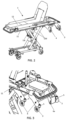
- FIG. 2 shows a perspective view of a stretcher (1) equipped with an anchoring system according to the present invention.
- the stretcher (1) is fundamentally formed by a frame (11) having a rectangular shape with two lateral sides in the longitudinal direction, and rear and front sides perpendicular to the longitudinal direction.
- a horizontal surface (12) which is usually cushioned, is fixed to the frame (11) so as to allow the patient to lie or sit down on same.
- rear retractable legs (13t) and front retractable legs (13d), respectively are fixed to the frame (11) on the lower part thereof.
- Retractable legs (13t, 13d) are known in the art and can be implemented in different ways, although as can be seen in Figure 2 they adopt a scissor structure which allows alternating between an extended position and a folded up position.
- the free ends of the retractable legs (13t, 13d) comprise wheels which allow moving the stretcher (1) over the floor or ground before introducing it into the ambulance.
- This stretcher (1) also includes a pair of first auxiliary wheels (3) fixed to the side bars of the frame (11) in a front portion of said side bars, as can be seen in further detail in Figure 3 .
- first auxiliary wheels (3) are fixed through a rigid connecting element to the front end of the side bars of the frame (11).
- a pair of second auxiliary wheels (4) is located a greater distance away from the front end of the side bars of the frame (11) in a fixed manner.
- the first and second auxiliary wheels (3, 4) are aligned in twos for the purpose of allowing them to be introduced into the rails (2) which will be described below.
- Centering rollers (5) which are fixed to the connecting elements between the auxiliary wheels (3, 4) and the side bars of the frame (11) in this example, are also seen in Figure 3 .
- the centering rollers (5) have a cylindrical shape and are oriented in the vertical direction. Their position, next to the auxiliary wheels (3, 4) and somewhat ahead of them, allow for their guiding function to make it easier to introduce the auxiliary wheels (3, 4) into the rails (2), as will be described in further detail below.
- the locking projection (6a) cooperating with a housing (6b) to lock the position of the stretcher (1) with respect to the rails (2) can also be seen in Figure 3 . It must be observed that this configuration of the locking means (6a, 6b) constitutes only one example, and that other types of mechanisms and other locations would be possible. The operation of the locking means (6a, 6b) will also be described herein in further detail below.
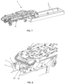
- Figures 4 to 6 show a structure which is designed for being fixed to the ambulance floor and includes the rails (2).
- the rails (2) are separated from one another by a distance equal to the gap between the auxiliary wheels (3, 4), and have an essentially C-shape formed by three segments: a lower horizontal segment (21), an intermediate vertical segment (22), and an upper horizontal segment (23).
- the distance between the upper surface of the lower horizontal segment (21) and the lower surface of the upper horizontal segment (23) is essentially equal to the diameter of the auxiliary wheels (3, 4).
- the auxiliary wheels (3, 4) can thereby roll in the longitudinal direction supported on the inner horizontal segment (21), its highest point almost rubbing against the upper horizontal segment (23).
- Figures 7 and 8 show a stretcher (1) with an anchoring system according to the invention at an initial moment of introducing it into an ambulance.
- the first auxiliary wheels (3) are introduced through the end of the rails (2).
- the centering rollers (5) help the paramedic to suitably center the first auxiliary wheels (3) with the open end of the rails, thereby making it easier to introduce it into the rails.
- the paramedic then pushes the stretcher (1) until also introducing the second auxiliary wheels (4) into the rails (2).
- the projection (6a) is introduced into the housing (6b) and thereby prevents any longitudinal movement of the stretcher (1).
- FIGs 9a and 9b schematically show an actual case in which the stretcher (1) is first introduced into the ambulance according to the process described above until the means (6a, 6b) are activated.
- the position of the stretcher (1) is locked with the two pairs of auxiliary wheels (3, 4) introduced into the rails (2).
- the retractable legs (13t, 13d) are folded up.
- the operation of folding up the retractable legs (13t, 13d) can be carried out by hand or automatically, for example by means of using mechanisms based on springs, hydraulic cylinders, electric motors, or the like. Once the legs (13t, 13d) are completely folded up, the paramedic must simply push the stretcher (1) until completely introducing it into the ambulance.
- this mode of use completely eliminates the need for the paramedic to support the weight of the stretcher (1) and the patient during the operation of introducing the stretcher (1) into the ambulance, thereby resolving the problems that have been described.
Landscapes
- Health & Medical Sciences (AREA)
- Public Health (AREA)
- Life Sciences & Earth Sciences (AREA)
- Animal Behavior & Ethology (AREA)
- General Health & Medical Sciences (AREA)
- Veterinary Medicine (AREA)
- Invalid Beds And Related Equipment (AREA)
- Handcart (AREA)
- Buckles (AREA)
Claims (8)
- System, umfassend ein Verankerungssystem und eine Trage (1), wobei die Trage (1) einen rechteckigen Rahmen (11) umfasst, der eine Oberfläche (12) zum Tragen des Patienten abstützt und an dem zwei Paar einklappbare Beine (13d, 13t), die an ihren freien Enden mit Rollen ausgestattet sind, befestigt sind, wobei das Verankerungssystem Folgendes umfasst:- ein Paar horizontaler Schienen (2), die mit einem Krankenwagenboden gekuppelt werden können;- eine Struktur, die darauf ausgelegt ist, an einem Krankenwagenboden befestigt zu werden und die Schienen (2) einschließt;- hintere einklappbare Beine (13t) und vordere einklappbare Beine (13d), die jeweils am unteren Teil des Rahmens (11) an dem Rahmen (11) befestigt sind, wobei die freien Enden der einklappbaren Beine (13t, 13d) Räder umfassen, die das Bewegen der Trage (1) über den Fußboden oder Untergrund gestatten, bevor die Trage (1) in den Krankenwagen gebracht wird;- ein paar erste Hilfsräder (3), wobei jedes erste Hilfsrad (3) steif am vorderen Endabschnitt einer entsprechenden Seitenstrebe des Rahmens (11) der Trage (1) befestigt ist und wobei die ersten Hilfsräder (3) in Längsrichtung gleitend mit dem genannten Paar horizontaler Schienen (2) kuppelbar sind,- ein Paar zweiter Hilfsräder (4), wobei jedes zweite Hilfsrad (4) steif an der entsprechenden Seitenstrebe des Rahmens (11) der Trage (1) in einer längs an das an derselben Seitenstrebe befestigte erste Hilfsrad (3) angrenzenden Position und mit diesem gefluchtet befestigt ist, so dass das Paar zweiter Hilfsräder (4) ebenfalls in Längsrichtung gleitend mit dem genannten Paar horizontaler Schienen (2) kuppelbar ist,wobei das Verankerungssystem dadurch gekennzeichnet ist,dass die zweiten Hilfsräder (4) in einer Längsposition zwischen der Anbringung der vorderen einklappbaren Beine am Rahmen (11) der Trage (1) und der Position der ersten Hilfsräder (3) platziert sind, unddadurch, dass das Profil des Paares horizontaler Schienen (2) ein unteres horizontales Segment (21) und ein oberes horizontales Segment (23) umfasst, die voneinander in einem im Wesentlichen dem Durchmesser der Hilfsräder (3, 4) entsprechenden Abstand entfernt sind, so dass, wenn die Hilfsräder (3, 4) in die Schienen (2) eingeführt werden, sie zwischen dem unteren horizontalen Segment (21) und dem oberen horizontalen Segment (23) der genannten Schienen (2) eingeschlossen sind und so jede vertikale Bewegung derselben verhindern.
- System nach Anspruch 1, wobei das Profil der Schienen (2) im Wesentlichen eine C-Form annimmt, die von dem unteren horizontalen Segment (21), einem vertikalen Zwischensegment (22) und dem oberen horizontalen Segment (23) gebildet wird.
- System nach einem der vorangegangenen Ansprüche, wobei der Abstand zwischen jedem zweiten Hilfsrad (4) und dem an derselben Seitenstrebe des Rahmens (11) befestigen ersten Hilfsrad (3) zwischen 10 cm und 100 cm beträgt.
- System nach einem beliebigen der vorangegangenen Ansprüche, das außerdem in einer an jedes der Hilfsräder (3, 4) angrenzenden Position angeordnete Zentrierwalzen (5) umfasst.
- System nach Anspruch 4, wobei die Zentrierwalzen (5) Walzen mit einer vertikalen Drehachse sind, die an einem Verbindungselement zwischen den Hilfsrädern (3, 4) und der entsprechenden Seitenstrebe des Rahmens (11) der Trage (1) befestigt sind.
- System nach einem beliebigen der vorangegangenen Ansprüche, das außerdem Verriegelungselemente (6a, 6b) umfasst, die automatisch aktiviert werden, nachdem das zweite Paar Hilfsräder (4) in die Schienen (2) eintritt, um jegliche Längsbewegung der Hilfsräder (3, 4) entlang der Schienen (2) zu verhindern.
- System nach Anspruch 6, das außerdem Elemente zum Entriegeln der Verriegelungselemente (6a, 6b) umfasst, die von einem hinteren Ende der Trage (1) aus betätigt werden können.
- System nach einem beliebigen der Ansprüche 6 bis 7, wobei die Verriegelungselemente (6a, 6b) einen Vorsprung (6a) mit Federantrieb, der steif am Rahmen (11) der Trage (1) befestigt ist, und ein entsprechendes Gehäuse (6b), das steif an dem Paar horizontaler Schienen (2) befestigt ist, umfassen.
Applications Claiming Priority (2)
| Application Number | Priority Date | Filing Date | Title |
|---|---|---|---|
| ES201730690A ES2642418B2 (es) | 2017-05-12 | 2017-05-12 | Sistema de anclaje de una camilla |
| PCT/ES2018/070333 WO2018206834A1 (es) | 2017-05-12 | 2018-04-27 | Sistema de anclaje de una camilla |
Publications (4)
| Publication Number | Publication Date |
|---|---|
| EP3636237A1 EP3636237A1 (de) | 2020-04-15 |
| EP3636237A4 EP3636237A4 (de) | 2020-12-16 |
| EP3636237C0 EP3636237C0 (de) | 2023-11-15 |
| EP3636237B1 true EP3636237B1 (de) | 2023-11-15 |
Family
ID=60269997
Family Applications (1)
| Application Number | Title | Priority Date | Filing Date |
|---|---|---|---|
| EP18797873.9A Active EP3636237B1 (de) | 2017-05-12 | 2018-04-27 | System zur verankerung eines betts |
Country Status (6)
| Country | Link |
|---|---|
| EP (1) | EP3636237B1 (de) |
| CN (1) | CN108514476B (de) |
| ES (1) | ES2642418B2 (de) |
| PL (1) | PL3636237T3 (de) |
| PT (1) | PT110716A (de) |
| WO (1) | WO2018206834A1 (de) |
Families Citing this family (6)
| Publication number | Priority date | Publication date | Assignee | Title |
|---|---|---|---|---|
| WO2020228945A1 (de) | 2019-05-14 | 2020-11-19 | Stollenwerk und Cie. GmbH Fabrik für Sanitätsausrüstungen | Verfahren zum be- und entladen eines krankentransportfahrzeugs |
| FR3115196B1 (fr) * | 2020-10-15 | 2023-03-17 | Antar Daouk | Brancard équipé de systèmes de fixation d’équipements médicaux amovibles |
| CN113335759B (zh) * | 2021-05-21 | 2022-09-06 | 江苏中奕和创智能科技有限公司 | 一种用于运输车载发电机组的支架 |
| ES1296849Y (es) | 2022-11-08 | 2023-04-25 | Kartsana S L | Camilla con cabezal abatible |
| GB2626598A (en) * | 2022-11-08 | 2024-07-31 | Kartsana S L | Chair cot with a folding headrest |
| CN116849933B (zh) * | 2023-08-09 | 2026-03-03 | 江西江铃汽车集团改装车股份有限公司 | 一种折叠担架平台 |
Family Cites Families (16)
| Publication number | Priority date | Publication date | Assignee | Title |
|---|---|---|---|---|
| DE1186579B (de) * | 1968-07-18 | 1965-02-04 | Binz & Co | Tragenbuehne fuer Krankenwagen |
| DE3476333D1 (en) * | 1984-01-24 | 1989-03-02 | Gmbh & Co Binz | Support for invalid beds, in particular support for stretcher |
| DE3613461A1 (de) * | 1986-04-22 | 1987-10-29 | Binz Gmbh & Co | Tragenlagerungsgestell |
| DE3734902C1 (de) * | 1987-10-15 | 1989-04-13 | Stollenwerk Fabrik Fuer Sanita | Fahrgeraet fuer eine Krankentrage |
| US5092722A (en) * | 1991-05-07 | 1992-03-03 | Ferno-Washington, Inc. | Automatically adaptable fastening system for wheeled cots and similar devices |
| JP2576008Y2 (ja) * | 1993-03-16 | 1998-07-09 | 株式会社アイチコーポレーション | 救出ロボットの救出台 |
| WO1998004228A1 (en) * | 1996-07-26 | 1998-02-05 | Huntleigh Technology Plc | A stretcher loading platform |
| CN1735395B (zh) * | 2003-01-15 | 2010-06-23 | 斯特赖克公司 | 救护车轻便床的装卸装置 |
| DE20312525U1 (de) * | 2003-08-13 | 2003-10-16 | PB MeTech GmbH, 73547 Lorch | Tragenlagerungsvorrichtung für den Patiententransport in Krankenwagen |
| ITPR20060093A1 (it) * | 2006-10-20 | 2008-04-21 | Spencer Italia Srl | Barella |
| WO2010053025A1 (ja) * | 2008-11-07 | 2010-05-14 | 株式会社松永製作所 | 六輪型ストレッチャー |
| EP2412356A1 (de) * | 2010-07-30 | 2012-02-01 | Kartsana S.L. | Vorrichtung zum Einschieben von Tragen in Krankentransportwagen |
| CN201879922U (zh) * | 2010-12-15 | 2011-06-29 | 周建平 | 救护车用担架车 |
| US20120237326A1 (en) * | 2011-03-16 | 2012-09-20 | Montrose Innovations, Llc | System and method for transferring a wheeled load into a transport vehicle |
| CN104783974B (zh) * | 2015-05-04 | 2017-02-22 | 江苏日新医疗设备有限公司 | 救护车用上车担架 |
| CN106176065B (zh) * | 2016-08-15 | 2018-09-21 | 江阴万事兴医疗器械股份有限公司 | 升降担架上车系统 |
-
2017
- 2017-05-12 ES ES201730690A patent/ES2642418B2/es active Active
-
2018
- 2018-04-27 WO PCT/ES2018/070333 patent/WO2018206834A1/es not_active Ceased
- 2018-04-27 PL PL18797873.9T patent/PL3636237T3/pl unknown
- 2018-04-27 EP EP18797873.9A patent/EP3636237B1/de active Active
- 2018-04-30 PT PT11071618A patent/PT110716A/pt unknown
- 2018-05-11 CN CN201810445613.4A patent/CN108514476B/zh active Active
Also Published As
| Publication number | Publication date |
|---|---|
| WO2018206834A1 (es) | 2018-11-15 |
| EP3636237A1 (de) | 2020-04-15 |
| ES2642418B2 (es) | 2018-07-09 |
| PL3636237T3 (pl) | 2024-04-08 |
| CN108514476B (zh) | 2021-03-02 |
| CN108514476A (zh) | 2018-09-11 |
| ES2642418A1 (es) | 2017-11-16 |
| EP3636237A4 (de) | 2020-12-16 |
| EP3636237C0 (de) | 2023-11-15 |
| PT110716A (pt) | 2018-11-12 |
Similar Documents
| Publication | Publication Date | Title |
|---|---|---|
| EP3636237B1 (de) | System zur verankerung eines betts | |
| US10987268B2 (en) | Emergency cot with a litter height adjustment mechanism | |
| KR101289000B1 (ko) | 운송수단에 배치되는 스트레쳐 및 스트레쳐 픽스츄어 | |
| US20160296389A1 (en) | System and method for transferring a wheeled load into a transport vehicle | |
| CN105899174B (zh) | 一种带活动折叠结构的担架 | |
| US20100313358A1 (en) | Nursing Bed with a Lateral Movement of Translation | |
| CN101001594A (zh) | 组合床装载和紧固系统 | |
| CN206183498U (zh) | 可折叠的手术平车 | |
| US10617579B2 (en) | Loading and unloading apparatus | |
| US11529272B2 (en) | Power lift | |
| US20070000056A1 (en) | Stretcher | |
| CN201082226Y (zh) | 可收展的双层担架支架装置 | |
| KR20200071308A (ko) | 휴대가 용이한 차량용 휠체어 리프트 | |
| EP2353564A2 (de) | Rollstuhlhalterung für Fahrzeuge | |
| KR101424388B1 (ko) | 장애인 차량용 리프트 장치 | |
| GB2559104A (en) | Barrier for a bed | |
| US7975333B2 (en) | Bed with interconnectable barrier elements | |
| CN105411781A (zh) | 一种人体转移装置 | |
| KR101730520B1 (ko) | 철도 차량의 다단식 승강 램프 | |
| JP2014125130A (ja) | 車両用昇降装置におけるプラットホームの延長装置 | |
| KR101954648B1 (ko) | 이동식 리프트 장치 | |
| US10327968B1 (en) | Jumpseat for an emergency transport vehicle | |
| US1170688A (en) | Ambulance stretcher-support. | |
| KR102808495B1 (ko) | 다인 후송 구급차 | |
| RU144497U1 (ru) | Средство трансформации для мягкой мебели |
Legal Events
| Date | Code | Title | Description |
|---|---|---|---|
| STAA | Information on the status of an ep patent application or granted ep patent |
Free format text: STATUS: THE INTERNATIONAL PUBLICATION HAS BEEN MADE |
|
| PUAI | Public reference made under article 153(3) epc to a published international application that has entered the european phase |
Free format text: ORIGINAL CODE: 0009012 |
|
| STAA | Information on the status of an ep patent application or granted ep patent |
Free format text: STATUS: REQUEST FOR EXAMINATION WAS MADE |
|
| 17P | Request for examination filed |
Effective date: 20191204 |
|
| AK | Designated contracting states |
Kind code of ref document: A1 Designated state(s): AL AT BE BG CH CY CZ DE DK EE ES FI FR GB GR HR HU IE IS IT LI LT LU LV MC MK MT NL NO PL PT RO RS SE SI SK SM TR |
|
| AX | Request for extension of the european patent |
Extension state: BA ME |
|
| DAV | Request for validation of the european patent (deleted) | ||
| DAX | Request for extension of the european patent (deleted) | ||
| A4 | Supplementary search report drawn up and despatched |
Effective date: 20201111 |
|
| RIC1 | Information provided on ipc code assigned before grant |
Ipc: A61G 3/08 20060101AFI20201106BHEP Ipc: A61G 3/02 20060101ALI20201106BHEP Ipc: A61G 1/02 20060101ALI20201106BHEP |
|
| P01 | Opt-out of the competence of the unified patent court (upc) registered |
Effective date: 20230306 |
|
| GRAP | Despatch of communication of intention to grant a patent |
Free format text: ORIGINAL CODE: EPIDOSNIGR1 |
|
| STAA | Information on the status of an ep patent application or granted ep patent |
Free format text: STATUS: GRANT OF PATENT IS INTENDED |
|
| INTG | Intention to grant announced |
Effective date: 20230703 |
|
| GRAS | Grant fee paid |
Free format text: ORIGINAL CODE: EPIDOSNIGR3 |
|
| GRAA | (expected) grant |
Free format text: ORIGINAL CODE: 0009210 |
|
| STAA | Information on the status of an ep patent application or granted ep patent |
Free format text: STATUS: THE PATENT HAS BEEN GRANTED |
|
| AK | Designated contracting states |
Kind code of ref document: B1 Designated state(s): AL AT BE BG CH CY CZ DE DK EE ES FI FR GB GR HR HU IE IS IT LI LT LU LV MC MK MT NL NO PL PT RO RS SE SI SK SM TR |
|
| REG | Reference to a national code |
Ref country code: CH Ref legal event code: EP Ref country code: GB Ref legal event code: FG4D |
|
| REG | Reference to a national code |
Ref country code: DE Ref legal event code: R096 Ref document number: 602018061174 Country of ref document: DE |
|
| REG | Reference to a national code |
Ref country code: IE Ref legal event code: FG4D |
|
| U01 | Request for unitary effect filed |
Effective date: 20231124 |
|
| U07 | Unitary effect registered |
Designated state(s): AT BE BG DE DK EE FI FR IT LT LU LV MT NL PT SE SI Effective date: 20231205 |
|
| P04 | Withdrawal of opt-out of the competence of the unified patent court (upc) registered |
Effective date: 20231201 |
|
| PG25 | Lapsed in a contracting state [announced via postgrant information from national office to epo] |
Ref country code: GR Free format text: LAPSE BECAUSE OF FAILURE TO SUBMIT A TRANSLATION OF THE DESCRIPTION OR TO PAY THE FEE WITHIN THE PRESCRIBED TIME-LIMIT Effective date: 20240216 |
|
| PG25 | Lapsed in a contracting state [announced via postgrant information from national office to epo] |
Ref country code: IS Free format text: LAPSE BECAUSE OF FAILURE TO SUBMIT A TRANSLATION OF THE DESCRIPTION OR TO PAY THE FEE WITHIN THE PRESCRIBED TIME-LIMIT Effective date: 20240315 |
|
| PG25 | Lapsed in a contracting state [announced via postgrant information from national office to epo] |
Ref country code: ES Free format text: LAPSE BECAUSE OF FAILURE TO SUBMIT A TRANSLATION OF THE DESCRIPTION OR TO PAY THE FEE WITHIN THE PRESCRIBED TIME-LIMIT Effective date: 20231115 |
|
| PG25 | Lapsed in a contracting state [announced via postgrant information from national office to epo] |
Ref country code: IS Free format text: LAPSE BECAUSE OF FAILURE TO SUBMIT A TRANSLATION OF THE DESCRIPTION OR TO PAY THE FEE WITHIN THE PRESCRIBED TIME-LIMIT Effective date: 20240315 Ref country code: GR Free format text: LAPSE BECAUSE OF FAILURE TO SUBMIT A TRANSLATION OF THE DESCRIPTION OR TO PAY THE FEE WITHIN THE PRESCRIBED TIME-LIMIT Effective date: 20240216 Ref country code: ES Free format text: LAPSE BECAUSE OF FAILURE TO SUBMIT A TRANSLATION OF THE DESCRIPTION OR TO PAY THE FEE WITHIN THE PRESCRIBED TIME-LIMIT Effective date: 20231115 |
|
| U20 | Renewal fee for the european patent with unitary effect paid |
Year of fee payment: 7 Effective date: 20240425 |
|
| PG25 | Lapsed in a contracting state [announced via postgrant information from national office to epo] |
Ref country code: RS Free format text: LAPSE BECAUSE OF FAILURE TO SUBMIT A TRANSLATION OF THE DESCRIPTION OR TO PAY THE FEE WITHIN THE PRESCRIBED TIME-LIMIT Effective date: 20231115 Ref country code: NO Free format text: LAPSE BECAUSE OF FAILURE TO SUBMIT A TRANSLATION OF THE DESCRIPTION OR TO PAY THE FEE WITHIN THE PRESCRIBED TIME-LIMIT Effective date: 20240215 Ref country code: HR Free format text: LAPSE BECAUSE OF FAILURE TO SUBMIT A TRANSLATION OF THE DESCRIPTION OR TO PAY THE FEE WITHIN THE PRESCRIBED TIME-LIMIT Effective date: 20231115 |
|
| PG25 | Lapsed in a contracting state [announced via postgrant information from national office to epo] |
Ref country code: SK Free format text: LAPSE BECAUSE OF FAILURE TO SUBMIT A TRANSLATION OF THE DESCRIPTION OR TO PAY THE FEE WITHIN THE PRESCRIBED TIME-LIMIT Effective date: 20231115 |
|
| PG25 | Lapsed in a contracting state [announced via postgrant information from national office to epo] |
Ref country code: SM Free format text: LAPSE BECAUSE OF FAILURE TO SUBMIT A TRANSLATION OF THE DESCRIPTION OR TO PAY THE FEE WITHIN THE PRESCRIBED TIME-LIMIT Effective date: 20231115 Ref country code: SK Free format text: LAPSE BECAUSE OF FAILURE TO SUBMIT A TRANSLATION OF THE DESCRIPTION OR TO PAY THE FEE WITHIN THE PRESCRIBED TIME-LIMIT Effective date: 20231115 Ref country code: RO Free format text: LAPSE BECAUSE OF FAILURE TO SUBMIT A TRANSLATION OF THE DESCRIPTION OR TO PAY THE FEE WITHIN THE PRESCRIBED TIME-LIMIT Effective date: 20231115 |
|
| REG | Reference to a national code |
Ref country code: DE Ref legal event code: R097 Ref document number: 602018061174 Country of ref document: DE |
|
| PLBE | No opposition filed within time limit |
Free format text: ORIGINAL CODE: 0009261 |
|
| STAA | Information on the status of an ep patent application or granted ep patent |
Free format text: STATUS: NO OPPOSITION FILED WITHIN TIME LIMIT |
|
| 26N | No opposition filed |
Effective date: 20240819 |
|
| PG25 | Lapsed in a contracting state [announced via postgrant information from national office to epo] |
Ref country code: MC Free format text: LAPSE BECAUSE OF FAILURE TO SUBMIT A TRANSLATION OF THE DESCRIPTION OR TO PAY THE FEE WITHIN THE PRESCRIBED TIME-LIMIT Effective date: 20231115 |
|
| PG25 | Lapsed in a contracting state [announced via postgrant information from national office to epo] |
Ref country code: MC Free format text: LAPSE BECAUSE OF FAILURE TO SUBMIT A TRANSLATION OF THE DESCRIPTION OR TO PAY THE FEE WITHIN THE PRESCRIBED TIME-LIMIT Effective date: 20231115 |
|
| REG | Reference to a national code |
Ref country code: CH Ref legal event code: PL |
|
| P05 | Withdrawal of opt-out of the competence of the unified patent court (upc) changed |
Free format text: CASE NUMBER: APP_590421/2023 Effective date: 20231205 |
|
| PG25 | Lapsed in a contracting state [announced via postgrant information from national office to epo] |
Ref country code: CH Free format text: LAPSE BECAUSE OF NON-PAYMENT OF DUE FEES Effective date: 20240430 |
|
| PG25 | Lapsed in a contracting state [announced via postgrant information from national office to epo] |
Ref country code: IE Free format text: LAPSE BECAUSE OF NON-PAYMENT OF DUE FEES Effective date: 20240427 |
|
| U20 | Renewal fee for the european patent with unitary effect paid |
Year of fee payment: 8 Effective date: 20250422 |
|
| PGFP | Annual fee paid to national office [announced via postgrant information from national office to epo] |
Ref country code: PL Payment date: 20250424 Year of fee payment: 8 |
|
| PGFP | Annual fee paid to national office [announced via postgrant information from national office to epo] |
Ref country code: GB Payment date: 20250422 Year of fee payment: 8 |
|
| PGFP | Annual fee paid to national office [announced via postgrant information from national office to epo] |
Ref country code: TR Payment date: 20250416 Year of fee payment: 8 |
|
| PGFP | Annual fee paid to national office [announced via postgrant information from national office to epo] |
Ref country code: CZ Payment date: 20250423 Year of fee payment: 8 |
|
| PG25 | Lapsed in a contracting state [announced via postgrant information from national office to epo] |
Ref country code: CY Free format text: LAPSE BECAUSE OF FAILURE TO SUBMIT A TRANSLATION OF THE DESCRIPTION OR TO PAY THE FEE WITHIN THE PRESCRIBED TIME-LIMIT; INVALID AB INITIO Effective date: 20180427 |
|
| PG25 | Lapsed in a contracting state [announced via postgrant information from national office to epo] |
Ref country code: HU Free format text: LAPSE BECAUSE OF FAILURE TO SUBMIT A TRANSLATION OF THE DESCRIPTION OR TO PAY THE FEE WITHIN THE PRESCRIBED TIME-LIMIT; INVALID AB INITIO Effective date: 20180427 |