EP3636104B1 - Coupling device for a drawer guide - Google Patents
Coupling device for a drawer guide Download PDFInfo
- Publication number
- EP3636104B1 EP3636104B1 EP19199102.5A EP19199102A EP3636104B1 EP 3636104 B1 EP3636104 B1 EP 3636104B1 EP 19199102 A EP19199102 A EP 19199102A EP 3636104 B1 EP3636104 B1 EP 3636104B1
- Authority
- EP
- European Patent Office
- Prior art keywords
- longitudinal strut
- longitudinal
- strut
- coupling part
- detent
- Prior art date
- Legal status (The legal status is an assumption and is not a legal conclusion. Google has not performed a legal analysis and makes no representation as to the accuracy of the status listed.)
- Active
Links
- 230000008878 coupling Effects 0.000 title claims description 84
- 238000010168 coupling process Methods 0.000 title claims description 84
- 238000005859 coupling reaction Methods 0.000 title claims description 84
- 238000007373 indentation Methods 0.000 claims description 12
- 230000001154 acute effect Effects 0.000 claims description 3
- 238000004519 manufacturing process Methods 0.000 description 5
- 239000000463 material Substances 0.000 description 5
- 238000005452 bending Methods 0.000 description 2
- 238000005096 rolling process Methods 0.000 description 2
- 238000001746 injection moulding Methods 0.000 description 1
- 238000000034 method Methods 0.000 description 1
- 230000000284 resting effect Effects 0.000 description 1
- 230000000630 rising effect Effects 0.000 description 1
Images


Classifications
-
- A—HUMAN NECESSITIES
- A47—FURNITURE; DOMESTIC ARTICLES OR APPLIANCES; COFFEE MILLS; SPICE MILLS; SUCTION CLEANERS IN GENERAL
- A47B—TABLES; DESKS; OFFICE FURNITURE; CABINETS; DRAWERS; GENERAL DETAILS OF FURNITURE
- A47B88/00—Drawers for tables, cabinets or like furniture; Guides for drawers
- A47B88/40—Sliding drawers; Slides or guides therefor
- A47B88/423—Fastening devices for slides or guides
- A47B88/427—Fastening devices for slides or guides at drawer side
- A47B2088/4278—Quick-release clip
Definitions
- the invention relates to a device for coupling a drawer to a running rail of a pull-out slide according to the preamble of claim 1.
- a device for coupling a drawer to a running rail of a pull-out slide which has a fastening means for fastening the device to a drawer.
- the device has a spring-loaded latching element, by means of which the device can be connected to the running rail in a latching manner.
- the spring-loaded latching element can be brought into the latching coupling position or into a non-coupling position by means of an actuating element in which the latching element is not connected to the running rail in a latching manner.
- the disadvantage of the known coupling device is that differently designed devices must be kept ready for fastening the coupling device to the pull-out guide on the left and right.
- a device for coupling a drawer to a running rail of a pull-out runner which Has fastening means for fastening the device to the drawer.
- a latching element is provided for connecting the device to a running rail.
- the device comprises an actuating element for bringing the latching element into a coupling position in which the latching element is connected to the running rail in a latching manner.
- the fastening means, the latching element and the actuating element are integrally connected to one another to form a coupling part.
- the coupling part has longitudinal struts which run parallel to one another and from which the actuating element protrudes.
- the object of the present invention is to develop a device for coupling a drawer to a running rail of a pull-out guide in such a way that the assembly and manufacture of the coupling device are further simplified, with the intention in particular to simplify handling.
- the invention has the features of claim 1.
- the invention has the particular advantage that an integrally formed coupling part is provided which is suitable and provided for both the left-hand and the right-hand fastening of the drawer to a running rail.
- an integrally formed coupling part is provided which is suitable and provided for both the left-hand and the right-hand fastening of the drawer to a running rail.
- the fitter can use the same coupling part for the right and left coupling of the drawer to the running rail.
- Another advantage of the invention results from the one-piece design of the coupling part. The manufacturing effort can be reduced as a result.
- the actuating element has a connecting strut which connects the first longitudinal strut and to the second longitudinal strut and which has an indentation oriented in the direction of a base element of the coupling part disposes.
- the indentation enables simple manual grasping and handling of the actuating element.
- the connecting strut enables the longitudinal strut to be stiffened so that it can only be pivoted by applying an actuating force acting on the connecting strut.
- the coupling part is designed symmetrically to a running rail and / or a longitudinal strut of the coupling part running center plane of the coupling part.
- the symmetry results in particular from the longitudinal struts of the coupling part, which run parallel to one another and on each of which a latching element is formed on the outside.
- the coupling part advantageously has a structure that is easy to manufacture.
- the actuating element is designed in such a way that it can move both a first longitudinal strut and a parallel second longitudinal strut transversely to the extension thereof, so that a first latching element formed on the first longitudinal strut or a second latching element formed on the second longitudinal strut can be moved from the coupling position to the non-coupling position and vice versa.
- both the first latching element provided, for example, for a right side and the second latching element provided for a left side of the pull-out slide can be actuated with the same actuating element.
- the operating effort or process is the same for both longitudinal struts.
- the indentation extends up to the level of a half area of the longitudinal strut, so that when the actuating element is actuated, not only a force component parallel to the longitudinal strut, but also a force component transversely to the longitudinal strut is generated.
- the indentation is parabolic, so that the actuating element can be operated simply by placing a finger on it.
- the longitudinal struts and the actuating element have the same wall thickness.
- the wall thickness is chosen so that bending of the longitudinal strut is guaranteed.
- the longitudinal strut is flexible and / or resilient.
- a height adjustment device is arranged on the longitudinal strut, by means of which the drawer can be adjusted in height relative to the pull-out guide. This enables a height adjustment in a simple manner.
- the height adjustment device comprises a grip element which is pivotably connected to the longitudinal strut via a film hinge.
- a catch with a contact surface protrudes from the grip element and is guided in a recess of the same longitudinal strut.
- the catch enables the contact surface running along the catch to be fixed in a desired position in which an adjusting element protrudes from an edge plane of the longitudinal strut by a desired vertical distance.
- the height adjustment device is advantageously connected in one piece with the respective longitudinal strut, so that a combined coupling and height adjustment function is provided, preferably using a single material of the coupling part.
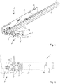
- a pull-out guide 1 for drawers usually consists of a plurality of rails.
- a carcass rail 2 has a plurality of bores 3, via which the carcass rail 2 can be fixed to a furniture carcass (furniture part), not shown, by means of a screw connection.
- the pull-out guide 1 comprises a running rail 4 which can usually be fixed to the side walls of a drawer (not shown).
- the running rail 4 is mounted in the direction of extension of the body rail 2 such that it can be moved relative to the same.
- the running rail 4 is coupled longitudinally displaceably to a middle rail 6 via rolling elements 5, while the middle rail 6 is longitudinally displaceably coupled to the body rail 2 via further rolling elements 5.
- a device for coupling the drawer to the running rail 4 of the pull-out slide 1 essentially consists of a one-piece coupling part 7 in which a height adjustment device 8 is integrated.
- the coupling part 7 is designed as a flat part which has a length l K and a width b K and a comparatively small height h K.
- the coupling part 7 has a rigid base element 9 which has fastening means 10, 11.
- the fastening means 10 On a front side of the coupling part 7, the fastening means 10 for fastening the coupling part 7 to a drawer panel is provided.
- the fastening means 10 can, for example, as Pin 10 may be formed, which is shown cut off in the figures on the front side of the coupling part 7.
- the fastening means 11 are provided, which are designed as bores.
- the coupling part 7 has two parallel longitudinal struts 12, 12 ', which each extend from the rigid base element 9 at a distance a from one another. At an end of the longitudinal struts 12, 12 'facing away from the base element 9, they each have a latching element 13, 13' on the outer flat sides.
- the latching element 13, 13 ′ is preferably designed as a hook element which, in a coupling position between the drawer and the running rail 4, engages or latches in a bore (not shown) in the running rail 4.
- the coupling part 7 rests with a first longitudinal strut 12 on a running rail 4 running on the left side of the drawer.
- the same coupling part 7 can also be connected in a latching manner to an opposite running rail 4 (not shown) that is connected to the drawer on the right-hand side.
- a second longitudinal strut 12 'of the coupling part 7 rests with its flat side on the right-hand running rail 4, not shown, with the latching element 13' formed on it engaging.
- the latching element 13, 13 ' protrudes laterally from the coupling part 7, protruding from an outer flat side of the longitudinal struts 12, 12'.
- the coupling part 7 further comprises an actuating element 14, by means of which both the first longitudinal strut 12 and the second longitudinal strut 12 ′ can be pivoted by a pivot angle ⁇ in a plane E of the coupling part 7.
- the first latching element 13 or the second latching element 13' can move from a coupling position connected to the running rail 4 be brought into a non-coupling position in which the first latching element 13 or the second latching element 13 'is in a disengaged position with respect to the running rail 4 or is not coupled to the running rail 4.
- the running rail 4 To move the coupling part 7 from the non-coupling position into the coupling position, the running rail 4 only needs to be moved relatively along the respective first longitudinal strut 12 or second longitudinal strut 12 'while resting on the same until the first latching element 13 or second latching element 13' into the bore the running rail 4 engages.
- the bore of the running rail 4 has such a vertical height that the coupling part 7 can be displaced linearly relative to the running rail 4 when the height adjustment device 8 is actuated.
- the actuating element 14 comprised a connecting strut 15, the ends of which are integrally formed on an end region 16 of the first longitudinal strut 12 and on an end region 16 'of the second longitudinal strut 12'.
- the connecting strut 15 runs between the two longitudinal struts 12, 12 'in a parabolic manner and forms an indentation 17.
- a pivot axis S of the longitudinal struts 12, 12 ' is located in an end region 16' of the first longitudinal strut 12 or second longitudinal strut 12 'facing the base element 9.
- the coupling part 7 is formed symmetrically with respect to a vertical center plane M V.
- a depth section or depth point 19 of the indentation 17 extends in the vertical center plane M V.
- the depth section 19 extends when projected onto the longitudinal strut 12, 12 'in a half section of the same which contains half a length l L of the longitudinal strut 12, 12' or half H of the length l L of the longitudinal strut 12, 12 '.
- the depth point 19 extends with a deviation of +/- 1/5 of the length l L of the longitudinal strut 12, 12 'from the Half H of the longitudinal strut 12, 12 '.
- the deviation from half of the longitudinal strut 12, 12 ' can also be greater, for example +/- 1 ⁇ 4 of a length l L of the longitudinal strut 12, 12' or +/- 1/3 of a length l L of the longitudinal strut 12, 12 '.
- the longitudinal struts 12, 12 'and the actuating element 14 have the same wall thickness w.
- the wall thickness w is in a range between 1 mm to 10 mm, preferably 1 mm to 5 mm, in particular 2 mm.
- the coupling part 7 is made of a plastic material.
- the base element 9 has an underside 20 which is interrupted in the area of the fastening means 11.
- the height adjustment device 8 is arranged in the area of the first longitudinal strut 12 and the second longitudinal strut 12 '. It comprises a grip element 21 which is pivotably connected to the longitudinal strut 12, 12 'via a film hinge 22 on the inside thereof.
- the film hinge 22 extends parallel to the pivot axis S and is arranged in the vicinity of the same.
- the grip element 21 forms an acute angle, preferably 45 °, with the respective longitudinal strut 12, 12 'from which the grip element 21 protrudes.
- a detent 23 with a contact surface 24 extends in an arc shape.
- the catch 23 has a toothing 25 which extends in an arc shape and interacts with an edge 26 of a recess 27 of the respective longitudinal strut 12, 12 '.
- the inclined surface 24 runs along the catch 23 or in the direction of extension of the catch 23, the inclined surface 24 rising from a free end of the catch 23 in the direction of the handle element 21, when the handle element 21 is adjusted from the starting position according to FIGS Figures 1 to 5 in an adjustment position according to Figures 6 to 10 the coupling part 7 is raised relative to the running rail 4 by a height h.
- the inclined surface 24 rests on the running rail 4.
- the inclined surface 24 runs on an underside of the catch 23, while the toothing 24 runs on an inside of the catch 23.
- the recess 27 has a recess 28.
- the recess 27 or depression 28 is arranged on an upper edge 29 of the longitudinal strut 12, 12 '.
- the grip element 21 can also be connected to the longitudinal strut 12, 12 'by another hinge or joint, instead of by means of the film hinge 22.
- the coupling part 7 can also be arranged non-symmetrically to the vertical center plane M V.
- a resilient tab can extend from the end region of the respective struts 12, 12 '.
- the space enclosed by the coupling part 7 is designed to be divided into three parts; it thus comprises three sections.
- the base element 9 is formed, which serves to stabilize and fasten the coupling part 7 to the drawer.
- the height adjustment device is in a central section 8 arranged.
- the actuating element 14 is arranged in a further section.
- the longitudinal struts 12, 12 ′ extend in the middle section and the section adjoining the middle section on a side of the middle section facing away from the base element 9.
- the three sections each have 1/3 the length l K of the coupling part 7.
- the longitudinal struts 12, 12 ′ have such a material thickness or wall thickness w and / or are made of such a material that, when the base section 9 is installed on the drawer 4, they lie flat against an outside of the running rail 4.
- the longitudinal struts 12, 12 ' are preferably designed to be resilient, and in the initial state they extend outwards at a small acute angle relative to a vertical center plane M V of the coupling part 7.
- the coupling part 7 can also have only a single longitudinal strut 12 or 12 'instead of two longitudinal struts 12, 12' protruding in the same direction. If the coupling part 7 only has the first longitudinal strut 12, the coupling part 7 is fastened exclusively to a left side of the drawer with fastening of the base element 9. If the coupling part 7 only has the second longitudinal strut 12 ', the coupling part 7 is attached exclusively to a right-hand side of the drawer via the base element 9.
- only an actuating lever protrudes from the end region 16 of the longitudinal strut 12 or the longitudinal strut 12 ′ facing away from the base element 9, which actuating lever can also be designed as a grip element. For example, removing the indentation 17, which is shown in the figures of the first embodiment of the invention, would be sufficient to form only the actuating lever.
- the coupling part 7 is preferably made of a plastic material and is manufactured by injection molding in one manufacturing step.
- the height adjustment device 8 does not have to be connected to the longitudinal strut 12, 12 'by the film hinge 22.
- a different joint or hinge can also be used as a connection, which, however, increases the manufacturing effort.
- the catch 23 can also alternatively be hinged directly to the longitudinal strut 12, 12 '. It goes without saying that the catch 23 and preferably the grip element 21 are rigid.
- the height adjustment device 8 is used for the relative adjustment of the coupling part 7 with respect to the running rail 4 in several vertical height positions.
- the height adjustment device 8 has an adjustment element which can be moved transversely to the running rail 4 and which, according to the first embodiment of the invention, is formed by the catch 23.
- the catch 23 is connected to the longitudinal strut 12 or 12 'via the grip element 21.
- the catch 23 can also be connected directly to the longitudinal strut 12, 12 '.
- the catch 23 cannot be arranged on an upper side of the coupling part 7 - as in the described embodiment and the figures - whereby it comes to rest on an upper side of the running rail 4 guided via the recess 27. Instead, it can also be arranged on a lower side of the coupling part 7 and rest with the inclined surface below the running rail 4 in various adjustment positions. In both cases, with increasing extension of the adjusting element 23 from the longitudinal strut 12, 12 'to the outside, the coupling part 2 would be raised relative to the running rail 4.
Landscapes
- Drawers Of Furniture (AREA)
- Lift-Guide Devices, And Elevator Ropes And Cables (AREA)
Description
Die Erfindung betrifft eine Vorrichtung zur Kopplung eines Schubkastens an einer Laufschiene einer Auszugsführung nach dem Oberbegriff des Patentanspruchs 1.The invention relates to a device for coupling a drawer to a running rail of a pull-out slide according to the preamble of
Aus der
Aus der
Aufgabe der vorliegenden Erfindung ist es, eine Vorrichtung zur Kopplung eines Schubkastens an einer Laufschiene einer Auszugsführung derart weiterzubilden, dass die Montage und die Herstellung der Kopplungsvorrichtung weiter vereinfacht werden, wobei insbesondere die Handhabung vereinfacht werden soll.The object of the present invention is to develop a device for coupling a drawer to a running rail of a pull-out guide in such a way that the assembly and manufacture of the coupling device are further simplified, with the intention in particular to simplify handling.
Zur Lösung dieser Aufgabe weist die Erfindung die Merkmale des Patentanspruchs 1 auf.To achieve this object, the invention has the features of
Die Erfindung weist insbesondere den Vorteil auf, dass ein einstückig ausgebildetes Kopplungsteil bereitgestellt wird, das sowohl zur linksseitigen als auch zur rechtsseitigen Befestigung des Schubkastens an einer Laufschiene geeignet und vorgesehen ist. Vorteilhaft kann hierdurch der Montageaufwand für eine an einem Möbelteil anzubringende Auszugsführung verringert werden. Der Monteur kann für die rechts- und linksseitige Kopplung des Schubkastens an der Laufschiene das gleiche Kopplungsteil verwenden. Ein weiterer Vorteil der Erfindung ergibt sich aus der einstückigen Ausbildung des Kopplungsteils. Der Herstellungsaufwand kann hierdurch reduziert werden.The invention has the particular advantage that an integrally formed coupling part is provided which is suitable and provided for both the left-hand and the right-hand fastening of the drawer to a running rail. In this way, the assembly effort for a pull-out guide to be attached to a furniture part can advantageously be reduced. The fitter can use the same coupling part for the right and left coupling of the drawer to the running rail. Another advantage of the invention results from the one-piece design of the coupling part. The manufacturing effort can be reduced as a result.
Nach der Erfindung weist das Betätigungselement eine die erste Längsstrebe und mit der zweiten Längsstrebe verbindende Verbindungsstrebe auf, die über eine in Richtung eines Basiselementes des Kopplungsteils orientierte Einbuchtung verfügt. Die Einbuchtung ermöglicht ein einfaches manuelles Erfassen und Handhaben des Betätigungselementes. Die Verbindungsstrebe ermöglicht eine Versteifung der Längsstrebe, so dass diese nur durch Aufwenden einer auf die Verbindungsstrebe wirkenden Betätigungskraft verschwenkt werden kann.According to the invention, the actuating element has a connecting strut which connects the first longitudinal strut and to the second longitudinal strut and which has an indentation oriented in the direction of a base element of the coupling part disposes. The indentation enables simple manual grasping and handling of the actuating element. The connecting strut enables the longitudinal strut to be stiffened so that it can only be pivoted by applying an actuating force acting on the connecting strut.
Nach einer bevorzugten Ausführungsform der Erfindung ist das Kopplungsteil symmetrisch zu einer Laufschiene und/oder eine Längsstrebe des Kopplungsteils verlaufenden Mittelebene des Kopplungsteils ausgebildet. Die Symmetrie ergibt sich insbesondere aufgrund der parallel zueinander verlaufenden Längsstreben des Kopplungsteils, an denen jeweils außenseitig ein Rastelement angeformt ist. Vorteilhaft hat das Kopplungsteil hierdurch einen einfach herzustellenden Aufbau.According to a preferred embodiment of the invention, the coupling part is designed symmetrically to a running rail and / or a longitudinal strut of the coupling part running center plane of the coupling part. The symmetry results in particular from the longitudinal struts of the coupling part, which run parallel to one another and on each of which a latching element is formed on the outside. As a result, the coupling part advantageously has a structure that is easy to manufacture.
Nach einer Weiterbildung der Erfindung ist das Betätigungselement derart ausgebildet, dass es sowohl eine erste Längsstrebe als auch eine parallel verlaufende zweite Längsstrebe quer zur Erstreckung derselben bewegen kann, so dass ein an der ersten Längsstrebe angeformtes erstes Rastelement oder ein an der zweiten Längsstrebe angeformtes zweites Rastelement von der Kopplungsstellung in die Nichtkopplungsstellung und vice versa verbracht werden kann. Vorteilhaft kann mit demselben Betätigungselement sowohl das beispielsweise für eine rechte Seite vorgesehene erste Rastelement und das für eine linke Seite der Auszugsführung vorgesehene zweite Rastelement betätigt werden. Der Betätigungsaufwand bzw.-ablauf ist für beide Längsstreben der gleiche.According to a further development of the invention, the actuating element is designed in such a way that it can move both a first longitudinal strut and a parallel second longitudinal strut transversely to the extension thereof, so that a first latching element formed on the first longitudinal strut or a second latching element formed on the second longitudinal strut can be moved from the coupling position to the non-coupling position and vice versa. Advantageously, both the first latching element provided, for example, for a right side and the second latching element provided for a left side of the pull-out slide can be actuated with the same actuating element. The operating effort or process is the same for both longitudinal struts.
Nach einer Weiterbildung der Erfindung reicht die Einbuchtung bis in die Höhe eines Hälftenbereiches der Längsstrebe, so dass bei Betätigen des Betätigungselementes nicht nur eine Kraftkomponente parallel zur Längsstrebe, sondern darüber hinaus eine Kraftkomponente quer zur Längsstrebe erzeugt wird. Durch Kombination dieser beiden Kraftkomponenten kann auf einfache Weise das erforderliche Biegemoment zum Entkoppeln bzw. Entriegeln des Rastelementes von der Laufschiene verringert werden.According to a further development of the invention, the indentation extends up to the level of a half area of the longitudinal strut, so that when the actuating element is actuated, not only a force component parallel to the longitudinal strut, but also a force component transversely to the longitudinal strut is generated. By combining these two force components, it is possible to achieve a simple Way, the required bending moment for decoupling or unlocking the locking element from the running rail can be reduced.
Nach einer Weiterbildung der Erfindung ist die Einbuchtung parabelförmig ausgebildet, so dass handhabungstechnisch einfach das Betätigungselement durch Anlegen eines Fingers ausgeübt werden kann.According to a further development of the invention, the indentation is parabolic, so that the actuating element can be operated simply by placing a finger on it.
Nach einer Weiterbildung der Erfindung weisen die Längsstreben und das Betätigungselement eine gleiche Wandstärke auf. Die Wandstärke ist so gewählt, dass ein Verbiegen der Längsstrebe gewährleistet ist. Die Längsstrebe ist flexibel und/oder nachgiebig ausgebildet.According to a further development of the invention, the longitudinal struts and the actuating element have the same wall thickness. The wall thickness is chosen so that bending of the longitudinal strut is guaranteed. The longitudinal strut is flexible and / or resilient.
Nach einer Weiterbildung der Erfindung ist an der Längsstrebe eine Höhenverstelleinrichtung angeordnet, mittels derer der Schubkasten relativ zu der Auszugsführung in der Höhe verstellt werden kann. Hierdurch wird auf einfache eine Höhenjustierung ermöglicht.According to a further development of the invention, a height adjustment device is arranged on the longitudinal strut, by means of which the drawer can be adjusted in height relative to the pull-out guide. This enables a height adjustment in a simple manner.
Nach einer Weiterbildung der Erfindung umfasst die Höhenverstelleinrichtung ein Griffelement, das über ein Filmscharnier mit der Längsstrebe schwenkbar verbunden ist. Von dem Griffelement ragt eine Raste mit einer Anlagefläche ab, die in einer Ausnehmung derselben Längsstrebe geführt ist. Die Raste ermöglicht die Festlegung der entlang der Raste verlaufenden Anlagefläche in einer gewünschten Stellung, in der ein Stellelement aus einer Randebene der Längsstrebe um eine gewünschte vertikale Distanz herausragt. Vorteilhaft ist die Höhenverstelleinrichtung einstückig mit der jeweiligen Längsstrebe verbunden, so dass vorzugsweise unter Verwendung eines einzigen Materials des Kopplungsteils eine kombinierte Kopplungs- und Höhenverstellfunktion gegeben ist.According to a further development of the invention, the height adjustment device comprises a grip element which is pivotably connected to the longitudinal strut via a film hinge. A catch with a contact surface protrudes from the grip element and is guided in a recess of the same longitudinal strut. The catch enables the contact surface running along the catch to be fixed in a desired position in which an adjusting element protrudes from an edge plane of the longitudinal strut by a desired vertical distance. The height adjustment device is advantageously connected in one piece with the respective longitudinal strut, so that a combined coupling and height adjustment function is provided, preferably using a single material of the coupling part.
Ein Ausführungsbeispiel der Erfindung wird nachfolgend anhand der Zeichnungen näher erläutert.An exemplary embodiment of the invention is explained in more detail below with reference to the drawings.
Es zeigen:
Figur 1- eine perspektivische Darstellung eines an einer linken Auszugsführung befestigten Kopplungsteils in einer Kopplungsstellung, ohne dass eine Höhenverstelleinrichtung betätigt ist (Ausgangsstellung der Höhenverstelleinrichtung),
Figur 2- eine Vorderansicht der Anordnung gemäß
Figur 1 Figur 3- eine perspektivische Darstellung des Kopplungsteils in einer Ausgangsstellung der Höhenverstelleinrichtung,
- Figur 4
- eine Draufsicht des Kopplungsteils gemäß
Figur 3 Figur 5- eine Vorderansicht des Kopplungsteils gemäß
Figur 3 - Figur 6
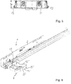
- eine perspektivische Darstellung des an der linken Auszugsführung befestigten Kopplungsteils in einer Höhenausgleichsstellung der Höhenverstelleinrichtung,
Figur 7- eine Vorderansicht der Anordnung gemäß
Figur 6 , Figur 8- eine perspektivische Darstellung des Kopplungsteils in der Höhenverstellposition desselben gemäß den
Figuren 6 und7 , Figur 9- eine Draufsicht des Kopplungsteils gemäß
Figur 8 Figur 10- eine Vorderansicht des Kopplungsteils gemäß
Figur 8
- Figure 1
- a perspective view of a coupling part attached to a left pull-out guide in a coupling position without a height adjustment device being actuated (starting position of the height adjustment device),
- Figure 2
- a front view of the arrangement according to
Figure 1 , - Figure 3
- a perspective view of the coupling part in an initial position of the height adjustment device,
- Figure 4
- a plan view of the coupling part according to
Figure 3 , - Figure 5
- a front view of the coupling part according to
Figure 3 , - Figure 6
- a perspective view of the coupling part attached to the left pull-out guide in a height adjustment position of the height adjustment device,
- Figure 7
- a front view of the arrangement according to
Figure 6 , - Figure 8
- a perspective view of the coupling part in the height adjustment position of the same according to FIG
Figures 6 and7th , - Figure 9
- a plan view of the coupling part according to
Figure 8 and - Figure 10
- a front view of the coupling part according to
Figure 8 .
Eine Auszugsführung 1 für Schubkästen (Möbelteil) besteht in üblicherweise aus einer Mehrzahl von Schienen. Eine Korpusschiene 2 weist eine Mehrzahl von Bohrungen 3 auf, über die die Korpusschiene 2 durch Schraubverbindung an einem nicht dargestellten Möbelkorpus (Möbelteil) festlegbar ist. Ferner umfasst die Auszugsführung 1 eine Laufschiene 4, die in üblicherweise an Seitenwänden eines nicht dargestellten Schubkastens festlegbar ist. Die Laufschiene 4 ist in Erstreckungsrichtung der Korpusschiene 2 verfahrbar zu derselben gelagert. Im vorliegenden Ausführungsbeispiel ist die Laufschiene 4 über Wälzkörper 5 mit einer Mittelschiene 6 längsverschieblich gekoppelt, während die Mittelschiene 6 über weitere Wälzkörper 5 längsverschieblich mit der Korpusschiene 2 gekoppelt ist.A pull-
Nach einer in den Figuren beschriebenen Ausführungsform der Erfindung besteht eine Vorrichtung zur Kopplung des Schubkastens mit der Laufschiene 4 der Auszugsführung 1 im Wesentlichen aus einem einstückigen Kopplungsteil 7, in dem eine Höhenverstelleinrichtung 8 integriert ist.According to one embodiment of the invention described in the figures, a device for coupling the drawer to the running rail 4 of the pull-out
Das Kopplungsteil 7 ist als ein flaches Teil ausgebildet, das eine Länge lK und einer Breite bK eine vergleichsweise geringe Höhe hK aufweist.The
Das Kopplungsteil 7 weist ein steifes Basiselement 9 auf, das über Befestigungsmittel 10, 11 verfügt. An einer Vorderseite des Kopplungsteils 7 ist das Befestigungsmittel 10 zur Befestigung des Kopplungsteils 7 an einer Schubkastenblende vorgesehen. Das Befestigungsmittel 10 kann beispielsweise als Zapfen 10 ausgebildet sein, der in den Figuren an der Vorderseite des Kopplungsteils 7 abgeschnitten dargestellt ist. Zur Befestigung des Kopplungsteils 7 an einer Unterseite des Schubkastens sind die Befestigungsmittel 11 vorgesehen, die als Bohrungen ausgebildet sind.The
Das Kopplungsteil 7 weist zwei parallele Längsstreben 12, 12' auf, die sich jeweils von dem starren Basiselement 9 in einem Abstand a zueinander erstrecken. An einem dem Basiselement 9 abgewandten Ende der Längsstreben 12, 12' weisen diese jeweils an äußeren Flachseiten ein Rastelement 13, 13' auf. Das Rastelement 13, 13' ist vorzugsweise als ein Hakenelement ausgebildet, das in einer Kopplungsstellung zwischen dem Schubkasten und der Laufschiene 4 in einer nicht dargestellten Bohrung der Laufschiene 4 eingreift bzw. einrastet.The
Im vorliegenden Ausführungsbeispiel liegt das Kopplungsteil 7 mit einer ersten Längsstrebe 12 an einer linksseitig an dem Schubkasten verlaufenden Laufschiene 4 an. Dasselbe Kopplungsteil 7 kann auch an einer gegenüberliegenden, nämlich rechtsseitig mit dem Schubkasten verbundenen nicht dargestellten Laufschiene 4 rastend verbunden sein. Zu diesem Zweck liegt eine zweite Längsstrebe 12' des Kopplungsteils 7 unter Eingreifen des an demselben angeformten Rastelementes 13' an der nicht dargestellten rechtsseitigen Laufschiene 4 mit ihrer Flachseite an.In the present exemplary embodiment, the
Das Rastelement 13, 13' ragt seitlich von dem Kopplungsteil 7 unter Abragen von einer äußeren Flachseite der Längsstreben 12, 12' ab.The latching
Das Kopplungsteil 7 umfasst ferner ein Betätigungselement 14, mittels dessen sowohl die erste Längsstrebe 12 als auch die zweite Längsstrebe 12' um einen Schwenkwinkel ϕ in einer Erstreckungsebene E des Kopplungsteils 7 verschwenkbar ist. Durch Verschwenken der ersten Längsstrebe 12 oder der zweiten Längsstrebe 12' kann das erste Rastelement 13 oder das zweite Rastelement 13' von einer mit der Laufschiene 4 verbundenen Kopplungsstellung in eine Nichtkopplungsstellung verbracht werden, in der sich das erste Rastelement 13 bzw. das zweite Rastelement 13' in einer Außereingriffstellung zu der Laufschiene 4 befindet bzw. nicht mit der Laufschiene 4 gekoppelt ist. Zum Verbringen des Kopplungsteils 7 von der Nichtkopplungsstellung in die Kopplungsstellung braucht die Laufschiene 4 lediglich relativ entlang der jeweiligen ersten Längsstrebe 12 bzw. zweiten Längsstrebe 12' unter Anlage an derselben verschoben werden, bis das erste Rastelement 13 bzw. zweite Rastelement 13' in die Bohrung der Laufschiene 4 einrastet. Die Bohrung der Laufschiene 4 weist eine solche vertikale Höhe auf, dass das Kopplungsteil 7 bei Betätigung der Höhenverstelleinrichtung 8 relativ zu der Laufschiene 4 linear verschoben werden kann.The
Das Betätigungselement 14 umfasste eine Verbindungsstrebe 15, deren Enden an einem Endbereich 16 der ersten Längsstrebe 12 und an einem Endbereich 16' der zweiten Längsstrebe 12' angeformt sind. Die Verbindungsstrebe 15 verläuft zwischen den beiden Längsstreben 12, 12' parabelförmig und bildet eine Einbuchtung 17 aus. Durch Anwenden einer Kraft F von außen auf die Einbuchtung 17 wird sowohl die erste Längsstrebe 12 als auch die zweite Längsstrebe 12' nach innen verschwenkt, so dass das jeweilige Rastelement 13, 13' aus der Kopplungsstellung in die Nichtkopplungsstellung verbringbar sind. Eine Schwenkachse S der Längsstreben 12, 12' befindet sich in einem dem Basiselement 9 zugewandten Endbereich 16' der ersten Längsstrebe 12 bzw. zweiten Längsstrebe 12'.The
Das Kopplungsteil 7 ist symmetrisch bezüglich einer vertikalen Mittelebene MV ausgebildet. Im vorliegenden Ausführungsbeispiel erstreckt sich ein Tiefenabschnitt bzw. Tiefenpunkt 19 der Einbuchtung 17 in der vertikalen Mittelebene MV. Der Tiefenabschnitt 19 erstreckt sich bei Projektion auf die Längsstrebe 12, 12' in einem Hälftenabschnitt derselben, der eine halbe Länge lL der Längsstrebe 12, 12' bzw. eine Hälfte H der Länge lL der Längsstrebe 12, 12' enthält. Im vorliegenden Ausführungsbeispiel erstreckt sich der Tiefenpunkt 19 in einer Abweichung von +/- 1/5 der Länge lL der Längsstrebe 12, 12' von der Hälfte H der der Längsstrebe 12, 12'. Alternativ kann die Abweichung zu der Hälfte der Längsstrebe 12, 12' auch größer sein, beispielsweise +/- ¼ einer Länge lL der Längsstrebe 12, 12' oder +/- 1/3 einer Länge lL der Längsstrebe 12, 12'.The
Je größer eine Tiefe tE der Einbuchtung 17 ist, desto größer ist bei Betätigung des Betätigungselementes 14 ein auf die Längsstrebe 12, 12' bzw. auf das Rastelement 13, 13' wirkenden Drehmomentes.The greater a depth t E of the
Die Längsstreben 12, 12' sowie das Betätigungselement 14 weisen eine gleiche Wandstärke w auf. Die Wandstärke w liegt in einem Bereich zwischen 1 mm bis 10 mm, vorzugsweise 1 mm bis 5 mm, insbesondere 2 mm.The longitudinal struts 12, 12 'and the
Das Kopplungsteil 7 ist aus einem Kunststoffmaterial hergestellt.The
Das Basiselement 9 weist eine Unterseite 20 auf, die im Bereich der Befestigungsmittel 11 unterbrochen ist.The
Die Höhenverstelleinrichtung 8 ist im Bereich der ersten Längsstrebe 12 und der zweiten Längsstrebe 12' angeordnet. Sie umfasst ein Griffelement 21, das über ein Filmscharnier 22 schwenkbar an einer Innenseite der Längsstrebe 12, 12' mit derselben verbunden ist. Das Filmscharnier 22 erstreckt sich parallel zu der Schwenkachse S und ist in der Nähe derselben angeordnet. In einer Ausgangsstellung gemäß den
Zur Aufnahme der Schrägfläche 24 weist die Ausnehmung 27 eine Vertiefung 28 auf. Die Ausnehmung 27 bzw. Vertiefung 28 ist an einer oberen Randkante 29 der Längsstrebe 12, 12' angeordnet.To accommodate the
Nach einer nicht dargestellten alternativen Ausführungsform der Erfindung kann das Griffelement 21 statt mittels des Filmscharniers 22 auch durch ein anderes Scharnier oder Gelenk mit der Längsstrebe 12, 12' verbunden sein.According to an alternative embodiment of the invention that is not shown, the
Nach einer nicht dargestellten alternativen Ausführungsform der Erfindung kann das Kopplungsteil 7 auch nichtsymmetrisch zu der vertikalen Mittelebene MV angeordnet sein. Beispielsweise kann statt der Verbindungstrebe 15 sich von dem Endbereich der jeweiligen Streben 12, 12' ein federnder Lappen erstrecken.According to an alternative embodiment of the invention, not shown, the
Der von dem Kopplungsteil 7 umfasste Raum ist dreigeteilt ausgebildet; er umfasst somit drei Abschnitte. In einem ersten Abschnitt ist das Basiselement 9 ausgebildet, welches zur Stabilisierung und Befestigung des Kopplungsteils 7 an dem Schubkasten dient. In einem mittleren Abschnitt ist die Höhenverstelleinrichtung 8 angeordnet. In einem weiteren Abschnitt ist das Betätigungselement 14 angeordnet. Die Längsstreben 12, 12' erstrecken sich im mittleren und zu dem sich auf einer dem Basiselement 9 abgewandten Seite des mittleren Abschnitt anschließenden Abschnitt.The space enclosed by the
Die drei Abschnitte weisen jeweils 1/3 der Länge lK des Kopplungsteils 7 auf.The three sections each have 1/3 the length l K of the
Die Längsstreben 12, 12' weisen eine solche Materialstärke bzw. Wandstärke w und/oder sind aus einem solchen Material hergestellt, dass sie im montierten Zustand des Basisabschnitts 9 an dem Schubkasten 4 flächig an einer Außenseite der Laufschiene 4 anliegen. Die Längsstreben 12, 12' sind vorzugsweise federnd ausgebildet, wobei sie im Ausgangszustand unter einem kleinen spitzen Winkel nach außen bezogen zu einer vertikalen Mittelebene MV des Kopplungsteils 7 verlaufen.The longitudinal struts 12, 12 ′ have such a material thickness or wall thickness w and / or are made of such a material that, when the
Nach einer nicht dargestellten Ausführungsform der Erfindung kann das Kopplungsteil 7 statt zwei in gleicher Richtung abragender Längsstreben 12, 12' auch lediglich eine einzige Längsstrebe 12 oder 12' aufweisen. Weist das Kopplungsteil 7 lediglich die erste Längsstrebe 12 auf, wird das Kopplungsteil 7 unter Befestigung des Basiselementes 9 ausschließlich an einer linken Seite des Schubkastens befestigt. Weist das Kopplungsteil 7 lediglich die zweite Längsstrebe 12' auf, wird das Kopplungsteil 7 über das Basiselement 9 ausschließlich an einer rechten Seite des Schubkastens befestigt. Bei dieser Ausführung ragt von zu dem Basiselement 9 abgewandten Endbereich 16 der Längsstrebe 12 oder der Längsstrebe 12' lediglich ein Betätigungshebel ab, der zugleich als ein Griffelement ausgebildet sein kann. Beispielsweise würde ein Entfernen der Einbuchtung 17, die in den Figuren der ersten Ausführungsform der Erfindung dargestellt ist, dazu ausreichen, lediglich den Betätigungshebel auszubilden.According to an embodiment of the invention that is not shown, the
Das Kopplungsteil 7 besteht vorzugsweise aus einem Kunststoffmaterial und wird durch Spritzgießen in einem Herstellungsschritt gefertigt.The
Die oben beschriebenen Merkmale der verschiedenen Ausführungsbeispiele können auch miteinander kombiniert werden, um die gestellte Aufgabe zu lösen. Insbesondere muss die Höhenverstelleinrichtung 8 nicht durch das Filmscharnier 22 mit der Längsstrebe 12, 12' verbunden sein. Alternativ kann als Verbindung auch ein anderes Gelenk oder Scharnier eingesetzt werden, was allerdings den Herstellungsaufwand erhöht. Darüber hinaus kann die Raste 23 auch alternativ direkt an der Längsstrebe 12, 12' angelenkt sein. Es versteht sich, dass die Raste 23 und vorzugsweise das Griffelement 21 starr ausgebildet sind.The features of the various exemplary embodiments described above can also be combined with one another in order to achieve the object set. In particular, the
Die Höhenverstelleinrichtung 8 dient zur relativen Verstellung des Kopplungsteils 7 bezüglich der Laufschiene 4 in mehrere vertikale Höhenpositionen. Die Höhenverstelleinrichtung 8 weist ein quer zur Laufschiene 4 bewegbares Verstellelement auf, das nach der ersten Ausführungsform der Erfindung durch die Raste 23 gebildet ist. Die Raste 23 ist nach der ersten Ausführungsform über das Griffelement 21 mit der Längsstrebe 12 bzw. 12' verbunden. Alternativ kann die Raste 23 auch direkt mit der Längsstrebe 12, 12' verbunden sein.The
Nach einer nicht dargestellten alternativen Ausführungsform der Erfindung kann die Raste 23 nicht - wie bei der beschriebenen Ausführungsform und den Figuren - an einer Oberseite des Kopplungsteils 7 angeordnet sein, wobei sie über die Ausnehmung 27 geführt an einer Oberseite der Laufschiene 4 zur Anlage kommt. Sie kann stattdessen auch an einer unteren Seite des Kopplungsteils 7 angeordnet sein und sich mit der Schrägfläche unterhalb der Laufschiene 4 in verschiedene Verstellpositionen anliegen. In beiden Fällen würde mit zunehmenden Ausfahren des Verstellelementes 23 von der Längsstrebe 12, 12' nach außen das Kopplungsteil 2 gegenüber der Laufschiene 4 angehoben werden.According to an alternative embodiment of the invention that is not shown, the
Claims (11)
- A device for coupling a drawer to a runner (4) of a drawer slide (1), comprising- a fastening means (10, 11) for fastening the device to the drawer,- a detent element (13, 13') for latchingly connecting the device to the runner (4),- an actuation element (14) for moving the detent element (13, 13') into a coupled position, in which the detent element (13, 13') is latchingly connected to the runner (4), and into a decoupled position, in which the detent element (13, 13') is not connected to the runner (4),- the fastening means (10, 11), the detent element (13, 13') and the actuation element (14) are integrally interconnected, forming a single coupling part (7),- the coupling part (7) has two longitudinal struts (12, 12') extending parallel to each other, on each outer sideof which the detent element (13, 13')is formed,- that the longitudinal struts (12, 12') having a first end (16) are formed on a base element (9) of the coupling part (7),said element having the fastening means (10, 11), and- that the actuation element (14),on an opposing side of the two longitudinal struts (12, 12'), protrudes from the same,characterized in that the actuation element (14) has a connecting strut (15) which connects the first longitudinal strut (12) to the second longitudinal strut (12'), wherein the connecting strut (15) has an indentation (17) directed toward the base element (9).
- The device according to Claim 1, characterized in that the coupling part (7) is formed symmetrically with respect to a vertical median plane (MV) extending parallel to the runner (4).
- The device according to Claim 1 or 2, characterized in that the actuation element (14) is configured in such a way that, when actuated, it moves a first detent element (13) formed on a first longitudinal strut (12) as well as a second detent element (13') formed on a second longitudinal strut (12') from the coupled position into the decoupled position or vice versa.
- The device according to any one of Claims 1 to 3, characterized in that the indentation (17) has a depth section (19), which when projected onto the first longitudinal strut (12) and/or the second longitudinal strut (12'), is arranged in a half-section (H) of the longitudinal strut (12, 12'), wherein the half-section (H) extends along the longitudinal strut (12, 12'), in an area of half of the longitudinal strut (12, 12'),with a deviation of +/- 1/3 of a length (IL)of the longitudinal strut (12, 12'), preferably +/- 1/4 of a length (IL) of the longitudinal strut (12, 12'), in particular +/- 1/5 of a length (IL) of the longitudinal strut (12, 12').
- The device according to any one of Claims 1 to 4, characterized in that the indentation (17) is parabolic.
- The device according to any one of Claims 1 to 5, characterized in that thefirst longitudinal strut (12) and the second longitudinal strut (12'), and also the actuation element (14), have the same wall thickness (w) .
- The device according to Claim 6, characterized in that the wall thickness (w) of the first longitudinal strut (12) and of the second longitudinal strut (12') and of the actuation element (14) is in a range of between 1 mm to 10 mm, preferably between 1 mm to 5 mm, and is in particular 2 mm.
- The device according to any one of Claims 1 to 7, characterized in that the longitudinal strut (12, 12) is formed elastically on a base element (9) of the coupling part (7) such that, in the state of the base element (9) in which the latter ismounted on the drawer, the longitudinal strut (12, 12') lies flatly on an outer side of the runner (4).
- The device according to any one of Claims 1 to 8, characterized in that a height adjustment mechanism (8) is arranged on the first longitudinal strut (12) and on the second longitudinal strut (12'), respectively.
- The device according to Claim 9, characterized in that the height adjustment mechanism (8) has a grip element (21), which is connected via a film hinge (22) to the longitudinal strut (12, 12'), and a detent (23),which has a contact surface (24) and which is guided in a recess (27) on an edge side (29) of the longitudinal strut (12, 12') such that, depending on an adjustment position of the contact surface (24) with respect to the longitudinal strut (12, 12'), the detent (23) protrudes outwardly from the longitudinal strut (12, 12'), with the beveled surface (24) in abutment on the runner (4).
- The device according to Claim 9 or 10, characterized in that the detent (23) has toothing (25), which extends arcuately along an acute adjustment angle area and that the contact surface (24) ascendstoward the grip element (21) from a free end of the detent (23), which endextends at the levelof a marginal edge (29) of the longitudinal strut (12, 12').
Priority Applications (1)
| Application Number | Priority Date | Filing Date | Title |
|---|---|---|---|
| PL19199102T PL3636104T3 (en) | 2018-10-12 | 2019-09-24 | Coupling device for a drawer guide |
Applications Claiming Priority (1)
| Application Number | Priority Date | Filing Date | Title |
|---|---|---|---|
| DE202018105867.3U DE202018105867U1 (en) | 2018-10-12 | 2018-10-12 | Coupling device for pullout guide |
Publications (3)
| Publication Number | Publication Date |
|---|---|
| EP3636104A2 EP3636104A2 (en) | 2020-04-15 |
| EP3636104A3 EP3636104A3 (en) | 2020-07-29 |
| EP3636104B1 true EP3636104B1 (en) | 2021-12-01 |
Family
ID=64334493
Family Applications (1)
| Application Number | Title | Priority Date | Filing Date |
|---|---|---|---|
| EP19199102.5A Active EP3636104B1 (en) | 2018-10-12 | 2019-09-24 | Coupling device for a drawer guide |
Country Status (5)
| Country | Link |
|---|---|
| EP (1) | EP3636104B1 (en) |
| DE (1) | DE202018105867U1 (en) |
| DK (1) | DK3636104T3 (en) |
| ES (1) | ES2907945T3 (en) |
| PL (1) | PL3636104T3 (en) |
Families Citing this family (1)
| Publication number | Priority date | Publication date | Assignee | Title |
|---|---|---|---|---|
| DE202020100555U1 (en) | 2020-02-03 | 2020-03-03 | Reme-Möbelbeschläge Gmbh | Coupling device for a drawer |
Family Cites Families (4)
| Publication number | Priority date | Publication date | Assignee | Title |
|---|---|---|---|---|
| ES1005541Y (en) * | 1988-02-16 | 1989-05-01 | Rioja Calvo Miguel Angel | QUICK MOORING DEVICE FOR EXTENSIBLE DRAWER GUIDES. |
| DE20107278U1 (en) | 2001-04-27 | 2001-08-02 | Paul Hettich Gmbh & Co., 32278 Kirchlengern | Device for producing a snap connection |
| DE102010017639A1 (en) * | 2010-06-29 | 2011-12-29 | Paul Hettich Gmbh & Co. Kg | Cupboard furniture with a pull-out part |
| US10240632B2 (en) * | 2015-08-06 | 2019-03-26 | Handy Button Machine Co. | Drawer guide system |
-
2018
- 2018-10-12 DE DE202018105867.3U patent/DE202018105867U1/en active Active
-
2019
- 2019-09-24 PL PL19199102T patent/PL3636104T3/en unknown
- 2019-09-24 DK DK19199102.5T patent/DK3636104T3/en active
- 2019-09-24 EP EP19199102.5A patent/EP3636104B1/en active Active
- 2019-09-24 ES ES19199102T patent/ES2907945T3/en active Active
Also Published As
| Publication number | Publication date |
|---|---|
| PL3636104T3 (en) | 2022-04-04 |
| DK3636104T3 (en) | 2022-03-07 |
| ES2907945T3 (en) | 2022-04-27 |
| EP3636104A3 (en) | 2020-07-29 |
| EP3636104A2 (en) | 2020-04-15 |
| DE202018105867U1 (en) | 2018-11-05 |
Similar Documents
| Publication | Publication Date | Title |
|---|---|---|
| DE69209619T2 (en) | DETACHABLE LOCK | |
| EP3478533B1 (en) | Longitudinal adjuster and vehicle seat | |
| DE3334510C2 (en) | ||
| DE202004002321U1 (en) | Positioning device for a multi-segment slide rail device for drawers | |
| DE3007690A1 (en) | ADJUSTABLE BRACKET, IN PARTICULAR DOOR HANDLE ARRANGEMENT FOR MOTOR VEHICLES | |
| DE602005002201T2 (en) | Telescopic guide for drawers | |
| DE19538988A1 (en) | Table bridging device | |
| DD298734A5 (en) | GUIDE FOR AN EXTRACT, DRAWER OD. DGL. | |
| EP3684223B1 (en) | Coupling device for drawer with subsequent latching | |
| WO2013132027A1 (en) | Fitting part for a vehicle seat, and a vehicle seat | |
| EP0123820B1 (en) | Device for the longitudinal adjustment of a ski binding | |
| DE202020006041U1 (en) | Arrangement for guiding a sliding door or folding sliding door | |
| EP3636104B1 (en) | Coupling device for a drawer guide | |
| DE102008050477A1 (en) | Cookware with removable handle or handle element | |
| DE202016000463U1 (en) | Runge for a commercial vehicle or trailer body | |
| DE202021100270U1 (en) | Adapter system for detachably coupling accessories to a vehicle luggage rack | |
| WO2022126164A1 (en) | Furniture fitting and item of furniture having such a furniture fitting | |
| EP3440293B1 (en) | Locking wedge system for releasably coupling a vehicle flap to a structural part of a vehicle body | |
| DE102019135805A1 (en) | Cover for closing an opening in a wall | |
| DE2939992A1 (en) | SLIDING ROOF FOR VEHICLES | |
| DE102022114415A1 (en) | Knife | |
| EP3287042B1 (en) | Pull-out guide for furniture parts | |
| EP3239443B1 (en) | Bearing assembly for a leaf which is pivotable relative to a frame | |
| DE19714132C2 (en) | Linking device for attaching an extension plate to a table | |
| DE102022132713A1 (en) | Locking device for a door |
Legal Events
| Date | Code | Title | Description |
|---|---|---|---|
| PUAI | Public reference made under article 153(3) epc to a published international application that has entered the european phase |
Free format text: ORIGINAL CODE: 0009012 |
|
| STAA | Information on the status of an ep patent application or granted ep patent |
Free format text: STATUS: THE APPLICATION HAS BEEN PUBLISHED |
|
| AK | Designated contracting states |
Kind code of ref document: A2 Designated state(s): AL AT BE BG CH CY CZ DE DK EE ES FI FR GB GR HR HU IE IS IT LI LT LU LV MC MK MT NL NO PL PT RO RS SE SI SK SM TR |
|
| AX | Request for extension of the european patent |
Extension state: BA ME |
|
| PUAL | Search report despatched |
Free format text: ORIGINAL CODE: 0009013 |
|
| AK | Designated contracting states |
Kind code of ref document: A3 Designated state(s): AL AT BE BG CH CY CZ DE DK EE ES FI FR GB GR HR HU IE IS IT LI LT LU LV MC MK MT NL NO PL PT RO RS SE SI SK SM TR |
|
| AX | Request for extension of the european patent |
Extension state: BA ME |
|
| RIC1 | Information provided on ipc code assigned before grant |
Ipc: A47B 88/427 20170101AFI20200619BHEP |
|
| STAA | Information on the status of an ep patent application or granted ep patent |
Free format text: STATUS: REQUEST FOR EXAMINATION WAS MADE |
|
| 17P | Request for examination filed |
Effective date: 20210128 |
|
| RBV | Designated contracting states (corrected) |
Designated state(s): AL AT BE BG CH CY CZ DE DK EE ES FI FR GB GR HR HU IE IS IT LI LT LU LV MC MK MT NL NO PL PT RO RS SE SI SK SM TR |
|
| GRAP | Despatch of communication of intention to grant a patent |
Free format text: ORIGINAL CODE: EPIDOSNIGR1 |
|
| STAA | Information on the status of an ep patent application or granted ep patent |
Free format text: STATUS: GRANT OF PATENT IS INTENDED |
|
| INTG | Intention to grant announced |
Effective date: 20210719 |
|
| GRAS | Grant fee paid |
Free format text: ORIGINAL CODE: EPIDOSNIGR3 |
|
| GRAA | (expected) grant |
Free format text: ORIGINAL CODE: 0009210 |
|
| STAA | Information on the status of an ep patent application or granted ep patent |
Free format text: STATUS: THE PATENT HAS BEEN GRANTED |
|
| AK | Designated contracting states |
Kind code of ref document: B1 Designated state(s): AL AT BE BG CH CY CZ DE DK EE ES FI FR GB GR HR HU IE IS IT LI LT LU LV MC MK MT NL NO PL PT RO RS SE SI SK SM TR |
|
| REG | Reference to a national code |
Ref country code: GB Ref legal event code: FG4D Free format text: NOT ENGLISH |
|
| REG | Reference to a national code |
Ref country code: AT Ref legal event code: REF Ref document number: 1450961 Country of ref document: AT Kind code of ref document: T Effective date: 20211215 Ref country code: CH Ref legal event code: EP |
|
| REG | Reference to a national code |
Ref country code: IE Ref legal event code: FG4D Free format text: LANGUAGE OF EP DOCUMENT: GERMAN |
|
| REG | Reference to a national code |
Ref country code: DE Ref legal event code: R096 Ref document number: 502019002897 Country of ref document: DE |
|
| REG | Reference to a national code |
Ref country code: NL Ref legal event code: FP |
|
| REG | Reference to a national code |
Ref country code: SE Ref legal event code: TRGR |
|
| REG | Reference to a national code |
Ref country code: DK Ref legal event code: T3 Effective date: 20220302 |
|
| REG | Reference to a national code |
Ref country code: LT Ref legal event code: MG9D |
|
| REG | Reference to a national code |
Ref country code: ES Ref legal event code: FG2A Ref document number: 2907945 Country of ref document: ES Kind code of ref document: T3 Effective date: 20220427 |
|
| PG25 | Lapsed in a contracting state [announced via postgrant information from national office to epo] |
Ref country code: RS Free format text: LAPSE BECAUSE OF FAILURE TO SUBMIT A TRANSLATION OF THE DESCRIPTION OR TO PAY THE FEE WITHIN THE PRESCRIBED TIME-LIMIT Effective date: 20211201 Ref country code: LT Free format text: LAPSE BECAUSE OF FAILURE TO SUBMIT A TRANSLATION OF THE DESCRIPTION OR TO PAY THE FEE WITHIN THE PRESCRIBED TIME-LIMIT Effective date: 20211201 Ref country code: FI Free format text: LAPSE BECAUSE OF FAILURE TO SUBMIT A TRANSLATION OF THE DESCRIPTION OR TO PAY THE FEE WITHIN THE PRESCRIBED TIME-LIMIT Effective date: 20211201 Ref country code: BG Free format text: LAPSE BECAUSE OF FAILURE TO SUBMIT A TRANSLATION OF THE DESCRIPTION OR TO PAY THE FEE WITHIN THE PRESCRIBED TIME-LIMIT Effective date: 20220301 |
|
| PG25 | Lapsed in a contracting state [announced via postgrant information from national office to epo] |
Ref country code: NO Free format text: LAPSE BECAUSE OF FAILURE TO SUBMIT A TRANSLATION OF THE DESCRIPTION OR TO PAY THE FEE WITHIN THE PRESCRIBED TIME-LIMIT Effective date: 20220301 Ref country code: LV Free format text: LAPSE BECAUSE OF FAILURE TO SUBMIT A TRANSLATION OF THE DESCRIPTION OR TO PAY THE FEE WITHIN THE PRESCRIBED TIME-LIMIT Effective date: 20211201 Ref country code: HR Free format text: LAPSE BECAUSE OF FAILURE TO SUBMIT A TRANSLATION OF THE DESCRIPTION OR TO PAY THE FEE WITHIN THE PRESCRIBED TIME-LIMIT Effective date: 20211201 Ref country code: GR Free format text: LAPSE BECAUSE OF FAILURE TO SUBMIT A TRANSLATION OF THE DESCRIPTION OR TO PAY THE FEE WITHIN THE PRESCRIBED TIME-LIMIT Effective date: 20220302 |
|
| PG25 | Lapsed in a contracting state [announced via postgrant information from national office to epo] |
Ref country code: SM Free format text: LAPSE BECAUSE OF FAILURE TO SUBMIT A TRANSLATION OF THE DESCRIPTION OR TO PAY THE FEE WITHIN THE PRESCRIBED TIME-LIMIT Effective date: 20211201 Ref country code: SK Free format text: LAPSE BECAUSE OF FAILURE TO SUBMIT A TRANSLATION OF THE DESCRIPTION OR TO PAY THE FEE WITHIN THE PRESCRIBED TIME-LIMIT Effective date: 20211201 Ref country code: RO Free format text: LAPSE BECAUSE OF FAILURE TO SUBMIT A TRANSLATION OF THE DESCRIPTION OR TO PAY THE FEE WITHIN THE PRESCRIBED TIME-LIMIT Effective date: 20211201 Ref country code: PT Free format text: LAPSE BECAUSE OF FAILURE TO SUBMIT A TRANSLATION OF THE DESCRIPTION OR TO PAY THE FEE WITHIN THE PRESCRIBED TIME-LIMIT Effective date: 20220401 Ref country code: EE Free format text: LAPSE BECAUSE OF FAILURE TO SUBMIT A TRANSLATION OF THE DESCRIPTION OR TO PAY THE FEE WITHIN THE PRESCRIBED TIME-LIMIT Effective date: 20211201 Ref country code: CZ Free format text: LAPSE BECAUSE OF FAILURE TO SUBMIT A TRANSLATION OF THE DESCRIPTION OR TO PAY THE FEE WITHIN THE PRESCRIBED TIME-LIMIT Effective date: 20211201 |
|
| REG | Reference to a national code |
Ref country code: DE Ref legal event code: R097 Ref document number: 502019002897 Country of ref document: DE |
|
| PG25 | Lapsed in a contracting state [announced via postgrant information from national office to epo] |
Ref country code: IS Free format text: LAPSE BECAUSE OF FAILURE TO SUBMIT A TRANSLATION OF THE DESCRIPTION OR TO PAY THE FEE WITHIN THE PRESCRIBED TIME-LIMIT Effective date: 20220401 |
|
| PGFP | Annual fee paid to national office [announced via postgrant information from national office to epo] |
Ref country code: NL Payment date: 20220823 Year of fee payment: 4 |
|
| PLBE | No opposition filed within time limit |
Free format text: ORIGINAL CODE: 0009261 |
|
| STAA | Information on the status of an ep patent application or granted ep patent |
Free format text: STATUS: NO OPPOSITION FILED WITHIN TIME LIMIT |
|
| PG25 | Lapsed in a contracting state [announced via postgrant information from national office to epo] |
Ref country code: AL Free format text: LAPSE BECAUSE OF FAILURE TO SUBMIT A TRANSLATION OF THE DESCRIPTION OR TO PAY THE FEE WITHIN THE PRESCRIBED TIME-LIMIT Effective date: 20211201 |
|
| PGFP | Annual fee paid to national office [announced via postgrant information from national office to epo] |
Ref country code: TR Payment date: 20220707 Year of fee payment: 4 Ref country code: SE Payment date: 20220707 Year of fee payment: 4 Ref country code: DK Payment date: 20220915 Year of fee payment: 4 |
|
| 26N | No opposition filed |
Effective date: 20220902 |
|
| PG25 | Lapsed in a contracting state [announced via postgrant information from national office to epo] |
Ref country code: SI Free format text: LAPSE BECAUSE OF FAILURE TO SUBMIT A TRANSLATION OF THE DESCRIPTION OR TO PAY THE FEE WITHIN THE PRESCRIBED TIME-LIMIT Effective date: 20211201 |
|
| PGFP | Annual fee paid to national office [announced via postgrant information from national office to epo] |
Ref country code: PL Payment date: 20220706 Year of fee payment: 4 Ref country code: FR Payment date: 20220921 Year of fee payment: 4 |
|
| PGFP | Annual fee paid to national office [announced via postgrant information from national office to epo] |
Ref country code: IT Payment date: 20220930 Year of fee payment: 4 Ref country code: ES Payment date: 20221006 Year of fee payment: 4 |
|
| PG25 | Lapsed in a contracting state [announced via postgrant information from national office to epo] |
Ref country code: MC Free format text: LAPSE BECAUSE OF FAILURE TO SUBMIT A TRANSLATION OF THE DESCRIPTION OR TO PAY THE FEE WITHIN THE PRESCRIBED TIME-LIMIT Effective date: 20211201 |
|
| REG | Reference to a national code |
Ref country code: CH Ref legal event code: PL |
|
| REG | Reference to a national code |
Ref country code: BE Ref legal event code: MM Effective date: 20220930 |
|
| PG25 | Lapsed in a contracting state [announced via postgrant information from national office to epo] |
Ref country code: LU Free format text: LAPSE BECAUSE OF NON-PAYMENT OF DUE FEES Effective date: 20220924 |
|
| PG25 | Lapsed in a contracting state [announced via postgrant information from national office to epo] |
Ref country code: LI Free format text: LAPSE BECAUSE OF NON-PAYMENT OF DUE FEES Effective date: 20220930 Ref country code: IE Free format text: LAPSE BECAUSE OF NON-PAYMENT OF DUE FEES Effective date: 20220924 Ref country code: CH Free format text: LAPSE BECAUSE OF NON-PAYMENT OF DUE FEES Effective date: 20220930 |
|
| PG25 | Lapsed in a contracting state [announced via postgrant information from national office to epo] |
Ref country code: BE Free format text: LAPSE BECAUSE OF NON-PAYMENT OF DUE FEES Effective date: 20220930 |
|
| PG25 | Lapsed in a contracting state [announced via postgrant information from national office to epo] |
Ref country code: HU Free format text: LAPSE BECAUSE OF FAILURE TO SUBMIT A TRANSLATION OF THE DESCRIPTION OR TO PAY THE FEE WITHIN THE PRESCRIBED TIME-LIMIT; INVALID AB INITIO Effective date: 20190924 |
|
| REG | Reference to a national code |
Ref country code: DK Ref legal event code: EBP Effective date: 20230930 |
|
| PG25 | Lapsed in a contracting state [announced via postgrant information from national office to epo] |
Ref country code: CY Free format text: LAPSE BECAUSE OF FAILURE TO SUBMIT A TRANSLATION OF THE DESCRIPTION OR TO PAY THE FEE WITHIN THE PRESCRIBED TIME-LIMIT Effective date: 20211201 |
|
| REG | Reference to a national code |
Ref country code: SE Ref legal event code: EUG |
|
| REG | Reference to a national code |
Ref country code: NL Ref legal event code: MM Effective date: 20231001 |
|
| GBPC | Gb: european patent ceased through non-payment of renewal fee |
Effective date: 20230924 |
|
| PG25 | Lapsed in a contracting state [announced via postgrant information from national office to epo] |
Ref country code: MK Free format text: LAPSE BECAUSE OF FAILURE TO SUBMIT A TRANSLATION OF THE DESCRIPTION OR TO PAY THE FEE WITHIN THE PRESCRIBED TIME-LIMIT Effective date: 20211201 |
|
| PG25 | Lapsed in a contracting state [announced via postgrant information from national office to epo] |
Ref country code: NL Free format text: LAPSE BECAUSE OF NON-PAYMENT OF DUE FEES Effective date: 20231001 |
|
| PG25 | Lapsed in a contracting state [announced via postgrant information from national office to epo] |
Ref country code: NL Free format text: LAPSE BECAUSE OF NON-PAYMENT OF DUE FEES Effective date: 20231001 |
|
| PG25 | Lapsed in a contracting state [announced via postgrant information from national office to epo] |
Ref country code: GB Free format text: LAPSE BECAUSE OF NON-PAYMENT OF DUE FEES Effective date: 20230924 |
|
| PG25 | Lapsed in a contracting state [announced via postgrant information from national office to epo] |
Ref country code: GB Free format text: LAPSE BECAUSE OF NON-PAYMENT OF DUE FEES Effective date: 20230924 Ref country code: FR Free format text: LAPSE BECAUSE OF NON-PAYMENT OF DUE FEES Effective date: 20230930 |
|
| PG25 | Lapsed in a contracting state [announced via postgrant information from national office to epo] |
Ref country code: SE Free format text: LAPSE BECAUSE OF NON-PAYMENT OF DUE FEES Effective date: 20230925 |
|
| PG25 | Lapsed in a contracting state [announced via postgrant information from national office to epo] |
Ref country code: MT Free format text: LAPSE BECAUSE OF FAILURE TO SUBMIT A TRANSLATION OF THE DESCRIPTION OR TO PAY THE FEE WITHIN THE PRESCRIBED TIME-LIMIT Effective date: 20211201 |
|
| PGFP | Annual fee paid to national office [announced via postgrant information from national office to epo] |
Ref country code: DE Payment date: 20240816 Year of fee payment: 6 |
|
| PG25 | Lapsed in a contracting state [announced via postgrant information from national office to epo] |
Ref country code: DK Free format text: LAPSE BECAUSE OF NON-PAYMENT OF DUE FEES Effective date: 20230930 |
|
| REG | Reference to a national code |
Ref country code: ES Ref legal event code: FD2A Effective date: 20241025 |
|
| PG25 | Lapsed in a contracting state [announced via postgrant information from national office to epo] |
Ref country code: DK Free format text: LAPSE BECAUSE OF NON-PAYMENT OF DUE FEES Effective date: 20230930 |