EP3287042B1 - Pull-out guide for furniture parts - Google Patents
Pull-out guide for furniture parts Download PDFInfo
- Publication number
- EP3287042B1 EP3287042B1 EP17186575.1A EP17186575A EP3287042B1 EP 3287042 B1 EP3287042 B1 EP 3287042B1 EP 17186575 A EP17186575 A EP 17186575A EP 3287042 B1 EP3287042 B1 EP 3287042B1
- Authority
- EP
- European Patent Office
- Prior art keywords
- locking
- pull
- guide
- hole portion
- locking element
- Prior art date
- Legal status (The legal status is an assumption and is not a legal conclusion. Google has not performed a legal analysis and makes no representation as to the accuracy of the status listed.)
- Active
Links
- 239000000463 material Substances 0.000 claims description 5
- 238000005452 bending Methods 0.000 claims description 3
- 238000006073 displacement reaction Methods 0.000 claims description 3
- 230000000903 blocking effect Effects 0.000 description 43
- 230000004888 barrier function Effects 0.000 description 4
- 238000004519 manufacturing process Methods 0.000 description 3
- 230000006978 adaptation Effects 0.000 description 1
- 230000000694 effects Effects 0.000 description 1
- 238000002347 injection Methods 0.000 description 1
- 239000007924 injection Substances 0.000 description 1
- 238000009434 installation Methods 0.000 description 1
Images


Classifications
-
- A—HUMAN NECESSITIES
- A47—FURNITURE; DOMESTIC ARTICLES OR APPLIANCES; COFFEE MILLS; SPICE MILLS; SUCTION CLEANERS IN GENERAL
- A47B—TABLES; DESKS; OFFICE FURNITURE; CABINETS; DRAWERS; GENERAL DETAILS OF FURNITURE
- A47B88/00—Drawers for tables, cabinets or like furniture; Guides for drawers
- A47B88/40—Sliding drawers; Slides or guides therefor
- A47B88/423—Fastening devices for slides or guides
- A47B88/427—Fastening devices for slides or guides at drawer side
- A47B2088/4276—Fastening devices for slides or guides at drawer side at drawer front via latch means or locking lever
Definitions
- the invention relates to a pullout guide for furniture parts according to the preamble of patent claim 1.
- the invention relates to a piece of furniture with such a drawer guide.
- U1 is a drawer guide for furniture parts is known in which to secure the drawer slide to the furniture part in the extension direction of a running rail of the drawer slide displaceably mounted locking element is provided which is engageable with a protruding nose in a receptacle of a front panel of the furniture part.
- a disadvantage of the known blocking element is that it is made in two parts, with a base Part is attached via a hook on the track.
- a movable slide part is mounted on the base part via longitudinal guides, wherein it is run in a blade-like manner on edge profiles on the base part. About locking elements, the movable slide member is held on the base part.
- a disadvantage of the known pullout guide that due to the two-part design of the blocking element of the production and assembly costs is relatively large.
- a drawer slide for furniture parts which comprises a carcass rail and a running rail.
- a locking unit is arranged at a rear end of the track rail.
- This locking unit comprises a lever arm, which is pivotable about a perpendicular to the extension of the running rail axis extending into a locking position and in a final locking position to a furniture part.
- an eccentric component is provided, which engages in a slot of the lever arm.
- Object of the present invention is to develop a drawer guide for furniture parts such that a backup of the drawer slide on the furniture part, especially in terms of manufacturing costs and installation, is reduced.
- the invention in conjunction with the preamble of claim 1, characterized in that the blocking element is integrally connected to a guide element, by means of which the blocking element is guided guided on a slot of the running rail in the extension direction of the same.
- a blocking element is integrally connected to a guide element, wherein the guide element is designed such that the blocking element is guided on a slot of a running rail of the furniture part in the same extension.
- the basic idea of the invention is to form a guide element on the blocking element in such a way that it fits together is guided guided guided with the blocking element on a slot of the running rail.
- the barrier unit thus formed has a simple structure and can serve as an effective Aushnaturebaum for drawer guides on furniture parts.
- the guide element is designed as a guide plate and the blocking element as a blocking plate, between which a connecting web is arranged.
- the connecting web has such a width relative to a width of the oblong hole and / or a clear distance between the guide plate and the locking plate is formed relative to a thickness of the running rail such that the locking unit or the locking element with play between a release position and a locking position and vice versa is movable.
- the adaptation of the dimension of the locking unit to the dimension of the slot allows a leadership of the blocking unit between the release and the blocking position of the same and on the other it leads to an avoidance of tilting when adjusting the locking unit between the release and blocking position.
- the slot is keyhole-shaped with a wide hole section and a narrow hole section.
- the wide hole portion is formed window-like manner that the guide member is pushed through by bending the locking unit through the wide hole portion, so that the locking unit is in a captive mounting position.
- the locking unit can optionally and subsequently be attached to the running rail of the pullout guide. There is no additional part required to obtain the locking unit in this mounting position.
- the connecting web is mounted in the narrow slot section in a self-locking manner in the extension direction of the slot or in the guide direction. Due to the self-locking effect, it is not necessary that additional catches required are to hold the locking element in the release position and / or in the locked position.
- a length of the connecting web is greater than a length of the narrow slot section.
- a transversely extending width of the locking plate and the guide plate are greater than a width of the wide hole portion, so that an undesirable removal or release of the locking unit is prevented by the pullout guide.
- the blocking element on a guide plate facing the flat side a stop member, which projects from this flat side, so that the blocking element abuts in the release position against a rear edge of the wide hole portion and in the blocking position against a front edge edge of the wide hole portion ,
- two stops are thereby formed, which cause defined end positions of the blocking unit.
- two guide bumps are provided on the blocking element as abutment parts, the outer spacing of which corresponds to one another with the width of the wide hole section.
- the stopper parts have an additional function. They serve as a guide when adjusting the locking element of the release position in the locked position and vice versa, preferably prevent self-locking. This results in a targeted and defined guidance in the extension direction or guide direction of the slot, which is preferably formed by a linear movement.
- the receptacle of the furniture part is formed in a recess on a front panel thereof.
- the easier-to-edit front panel can be selected as a place for recording.
- the barrier unit is made of a rigid material, preferably rigid plastic material.
- the barrier unit can be manufactured as injection molded inexpensively.
- the blocking element on a side facing away from the guide element flat side on a handle part, so that the handling of the locking unit is simplified.
- the locking unit and / or the slot locking means may have, so that, for example, the movement between the release and the locking position can be experienced haptically and / or the locking unit is fixed in the release and / or end position detent.
- this can improve the operability or the definition in the end positions.
- the locking unit may comprise a spring element, so that always acts a spring force on the locking element in the direction of the locking position.
- the spring element can be supported on the rear edge of the slot.
- the force required for the adjustment of the locking unit can be reduced in the locked position.
- a drawer guide for furniture parts can be designed as a full-extension guide or as a half-pull guide.
- the carcass rail 2 has a plurality of bores 3, by way of which the carcass rail 2 can be fixed by screw connection to the furniture carcass.
- the pullout guide comprises a running rail 4 which extends in the extension direction E of the carcass rail 2 and which is usually fixable on side walls of a furniture part 1 designed as a drawer.
- the running rail 4 is movably mounted in the extension direction E of the carcass rail 2 to the carcass rail 2.
- a locking unit 5 which integrally consists of a blocking element 6, a guide element 7 and a connecting element 8 connecting the blocking element 6 to the guide element 7.
- the blocking element 6 extends on the outside of a vertical wall 9 of the profile-like running rail 4, while the guide element 7 extends substantially on an inner side of this vertical wall 9.
- the same For holding the locking unit 5 on the running rail 4, the same has a slot 10 which extends in the extension direction E of the running rail 4.
- the slot 10 extends in a front end region 11 of the running rail 4, so that the locking unit 5 is easily accessible to an operator.
- the blocking element 6 has in a rear region of the same a laterally projecting handle portion 12, so that the locking element 6 and the locking unit 5 is simply manually displaceable between an example in FIG. 3 illustrated blocking position in which a arranged in the front region of the locking element 6 nose 13 engages in a receptacle 14 of a front panel 15 of the furniture part 1, and one example in FIG. 1 shown release position in which the nose 13 of the locking element 6 does not engage in the receptacle 14 of the front panel 15.
- a free edge of the nose 13 extends in the amount of a front end face 16 of the running rail 4 or slightly set back to this.
- the nose 13 In the blocking position, the nose 13 extends forward offset to the front end face 16, as seen from FIG. 2 is apparent.
- the slot 10 is keyhole-shaped with a wide hole portion 10 'and a narrow hole portion 10 ", see dashed line in the FIG. 7 ,
- the guide member 7 of the locking unit 5 is formed as a guide plate.
- the blocking element 6 of the blocking unit 5 is designed as a blocking plate.
- the connecting element 8 of the blocking unit 5 is designed as a connecting web.
- the guide plate 7 In the release position, the guide plate 7 is located substantially at the height of the wide slot portion 10 '. In the blocking position, the guide plate 7 is located substantially at the height of the narrow slot section 10 ". In the blocking position, the connecting web 8 extends essentially in the narrow slot section 10". In the release position, the connecting web 8 is partially in the narrow slot section 10 ", like out FIG. 8 is apparent.
- a transverse to the extending direction E width b V of the connecting element 8 is preferably smaller than a width b of the narrow elongated hole portion so that a movement of the locking unit 5 is ensured in the extension direction E with clearance L2 10 ".
- a clear distance a1 between the Locking plate 6 and the guide plate 7 is greater than a thickness d of the running rail 4 and the vertical wall 9 of the track rail 4, so that the movement of the locking unit 5 is ensured with play in the direction of extension E.
- the locking element 6 and the guide member 7 are so relative arranged to each other that a self-locking guide in the extension direction E is present.
- the guide bumps 17 are arranged in a rear area 18 of the blocking element 6, wherein an outer distance a F of the two guide bumps 17 substantially corresponds to a width b L1 of the wide slot section 10 '.
- the guide bumps 17 are in the release position at a rear edge edge 19 of the wide slot portion 10 ', see FIG. 8 ,
- the guide bumps 17 are in the blocking position at a front edge edge 20 of the wide slot portion 10 ', see FIG.
- a transverse to the extension direction width of the locking element and / or extending transversely to the extension direction width of the guide element is greater than a width of the wide hole portion.
- the one-piece locking unit 5 consists of a rigid material, in particular of a rigid plastic material.
- the blocking unit 5 can be designed as an injection-molded part.
- the guide bumps 17 also serve as stop members, since they abut in the release position against the rear edge edge 19 and in the locked position against the front edge edge 20 of the wide slot portion 10 '.
- only one stop member for example, in the middle of the locking element 6, be arranged.
- the desired leadership that counteracts the self-locking.
- the receptacle 14 of the front panel 15 is preferably formed as a recess whose transverse extent is greater than the transverse extent of the nose 13.
- the dimension of the recess is adapted to the nose 13 so that it is clamped in the locking position in the recess 14.
- the locking unit 5 in the direction of extension E have a number of locking means, so that a latching displacement of the locking unit 5 in the extension direction E during haptic can be seen.
- locking means may be provided, so that the locking unit 5 is held in the end positions (blocking position, release position) latching in the slot 10.
- the locking unit 5 may also have a spring element, by means of which a force acting in the direction of the locking position spring force is exerted on the locking element.
- the spring element can, for example, be supported on the rear edge edge 19 of the wide slot section 10 '.
- the spring element is integrally connected to the blocking unit 5 or blocking element 6.
Landscapes
- Drawers Of Furniture (AREA)
Description
Die Erfindung betrifft eine Auszugsführung für Möbelteile nach dem Oberbegriff des Patentanspruchs 1.The invention relates to a pullout guide for furniture parts according to the preamble of
Ferner betrifft die Erfindung ein Möbel mit einer solchen Auszugsführung.Furthermore, the invention relates to a piece of furniture with such a drawer guide.
Zur Sicherung von Auszugsführungen an Auszügen bzw. Möbelteilen ist es aus der
Aus der
Aus der
Aufgabe der vorliegenden Erfindung ist es, eine Auszugsführung für Möbelteile derart weiterzubilden, dass eine Sicherung der Auszugsführung an dem Möbelteil, insbesondere hinsichtlich Herstellungsaufwand und Montage, reduziert wird.Object of the present invention is to develop a drawer guide for furniture parts such that a backup of the drawer slide on the furniture part, especially in terms of manufacturing costs and installation, is reduced.
Zur Lösung dieser Aufgabe ist die Erfindung in Verbindung mit dem Oberbegriff des Patentanspruchs 1 dadurch gekennzeichnet, dass das Sperrelement einstückig mit einem Führungselement verbunden ist, mittels dessen das Sperrelement an einem Langloch der Laufschiene in Erstreckungsrichtung derselben geführt gelagert ist.To achieve this object, the invention in conjunction with the preamble of
Nach der Erfindung ist ein Sperrelement einstückig mit einem Führungselement verbunden, wobei das Führungselement derart ausgebildet ist, dass das Sperrelement an einem Langloch einer Laufschiene des Möbelteils in Erstreckung desselben geführt gelagert ist. Grundgedanke der Erfindung ist es, ein Führungselement an das Sperrelement so anzuformen, dass es zusammen mit dem Sperrelement an einem Langloch der Laufschiene geführt gelagert ist. Die so gebildete Sperreinheit weist einen einfachen Aufbau auf und kann als effektive Aushängsicherung für Auszugsführungen an Möbelteilen dienen.According to the invention, a blocking element is integrally connected to a guide element, wherein the guide element is designed such that the blocking element is guided on a slot of a running rail of the furniture part in the same extension. The basic idea of the invention is to form a guide element on the blocking element in such a way that it fits together is guided guided with the blocking element on a slot of the running rail. The barrier unit thus formed has a simple structure and can serve as an effective Aushängsicherung for drawer guides on furniture parts.
Nach einer bevorzugten Ausführungsform der Erfindung ist das Führungselement als Führungsplatte und das Sperrelement als Sperrplatte ausgebildet, zwischen denen ein Verbindungssteg angeordnet ist. Der Verbindungssteg weist eine solche Breite relativ zu einer Breite des Langlochs und/oder ein lichter Abstand zwischen der Führungsplatte und der Sperrplatte ist derart relativ zu einer Dicke der Laufschiene ausgebildet, dass die Sperreinheit bzw. das Sperrelement mit Spiel zwischen einer Freigabestellung und einer Sperrstellung und vice versa bewegbar ist. Die Anpassung der Dimension der Sperreinheit an die Dimension des Langlochs ermöglicht eine Führung der Sperreinheit zwischen der Freigabe- und der Sperrstellung desselben und zum anderen führt es zu einer Vermeidung von Verkanten bei Verstellung der Sperreinheit zwischen der Freigabe- und Sperrstellung.According to a preferred embodiment of the invention, the guide element is designed as a guide plate and the blocking element as a blocking plate, between which a connecting web is arranged. The connecting web has such a width relative to a width of the oblong hole and / or a clear distance between the guide plate and the locking plate is formed relative to a thickness of the running rail such that the locking unit or the locking element with play between a release position and a locking position and vice versa is movable. The adaptation of the dimension of the locking unit to the dimension of the slot allows a leadership of the blocking unit between the release and the blocking position of the same and on the other it leads to an avoidance of tilting when adjusting the locking unit between the release and blocking position.
Nach einer Weiterbildung der Erfindung ist das Langloch schlüssellochartig ausgebildet mit einem breiten Lochabschnitt und mit einem schmalen Lochabschnitt. Der breite Lochabschnitt ist derart fensterartig ausgebildet, dass das Führungselement durch Verbiegen der Sperreinheit durch den breiten Lochabschnitt durchsteckbar ist, so dass sich die Sperreinheit in einer unverlierbaren Montagestellung befindet. Vorteilhaft kann die Sperreinheit wahlweise und gegebenenfalls nachträglich an die Laufschiene der Auszugsführung angebracht werden. Es ist kein zusätzliches Teil erforderlich, um die Sperreinheit in dieser Montagestellung zu erhalten.According to a development of the invention, the slot is keyhole-shaped with a wide hole section and a narrow hole section. The wide hole portion is formed window-like manner that the guide member is pushed through by bending the locking unit through the wide hole portion, so that the locking unit is in a captive mounting position. Advantageously, the locking unit can optionally and subsequently be attached to the running rail of the pullout guide. There is no additional part required to obtain the locking unit in this mounting position.
Nach einer Weiterbildung der Erfindung ist der Verbindungssteg in den schmalen Langlochabschnitt selbsthemmend in Erstreckungsrichtung des Langlochs bzw. in Führungsrichtung gelagert. Durch die selbsthemmende Wirkung ist es nicht erforderlich, dass zusätzlich Verrastungen erforderlich sind, um das Sperrelement in der Freigabestellung und/oder in der Sperrstellung zu halten.According to a development of the invention, the connecting web is mounted in the narrow slot section in a self-locking manner in the extension direction of the slot or in the guide direction. Due to the self-locking effect, it is not necessary that additional catches required are to hold the locking element in the release position and / or in the locked position.
Nach einer Weiterbildung der Erfindung ist eine Länge des Verbindungssteges größer als eine Länge des schmalen Langlochabschnitts. Somit ist stets eine selbsthemmende Führung gewährleistet.According to a development of the invention, a length of the connecting web is greater than a length of the narrow slot section. Thus, a self-locking guide is always guaranteed.
Nach einer Weiterbildung der Erfindung sind eine in Querrichtung verlaufende Breite der Sperrplatte und der Führungsplatte größer als eine Breite des breiten Lochabschnitts, so dass ein unerwünschtes Entfernen bzw. Lösen der Sperreinheit von der Auszugsführung verhindert wird.According to a development of the invention, a transversely extending width of the locking plate and the guide plate are greater than a width of the wide hole portion, so that an undesirable removal or release of the locking unit is prevented by the pullout guide.
Nach einer Weiterbildung der Erfindung weist das Sperrelement auf einer der Führungsplatte zugewandten Flachseite ein Anschlagteil auf, das von dieser Flachseite abragt, so dass das Sperrelement in der Freigabestellung gegen eine rückseitige Randkante des breiten Lochabschnitts und in der Sperrstellung gegen eine vorderseitige Randkante des breiten Lochabschnitts anschlägt. Vorteilhaft werden hierdurch zwei Anschläge gebildet, die definierte Endstellungen der Sperreinheit bewirken.According to a development of the invention, the blocking element on a guide plate facing the flat side a stop member, which projects from this flat side, so that the blocking element abuts in the release position against a rear edge of the wide hole portion and in the blocking position against a front edge edge of the wide hole portion , Advantageously, two stops are thereby formed, which cause defined end positions of the blocking unit.
Nach einer Weiterbildung der Erfindung sind als Anschlagteile zwei Führungshöcker an dem Sperrelement vorgesehen, deren Außenabstand zueinander mit der Breite des breiten Lochabschnitts übereinstimmt. Vorteilhaft haben hierdurch die Anschlagteile eine zusätzliche Funktion. Sie dienen nämlich als Führungsmittel beim Verstellen des Sperrelementes von der Freigabestellung in die Sperrstellung und vice versa, wobei sie vorzugsweise eine Selbsthemmung verhindern. Hierdurch erfolgt eine gezielte und definierte Führung in Erstreckungsrichtung bzw. Führungsrichtung des Langlochs, die vorzugsweise durch eine Linearbewegung gebildet ist.According to a development of the invention, two guide bumps are provided on the blocking element as abutment parts, the outer spacing of which corresponds to one another with the width of the wide hole section. This advantageously the stopper parts have an additional function. They serve as a guide when adjusting the locking element of the release position in the locked position and vice versa, preferably prevent self-locking. This results in a targeted and defined guidance in the extension direction or guide direction of the slot, which is preferably formed by a linear movement.
Nach einer Weiterbildung der Erfindung ist die Aufnahme des Möbelteils in einer Vertiefung an einer Frontblende desselben ausgebildet. Vorteilhaft kann somit die leichter zu bearbeitende Frontblende als Ort für die Aufnahme ausgewählt werden.According to a development of the invention, the receptacle of the furniture part is formed in a recess on a front panel thereof. Advantageously, thus, the easier-to-edit front panel can be selected as a place for recording.
Nach einer Weiterbildung der Erfindung ist die Sperreinheit aus einem starren Material, vorzugsweise starren Kunststoffmaterial, hergestellt. Beispielsweise kann die Sperreinheit als Spritzgießteil kostengünstig hergestellt werden.According to a development of the invention, the barrier unit is made of a rigid material, preferably rigid plastic material. For example, the barrier unit can be manufactured as injection molded inexpensively.
Nach einer Weiterbildung der Erfindung weist das Sperrelement auf einer dem Führungselement abgewandten Flachseite ein Griffteil auf, so dass die Handhabung der Sperreinheit vereinfacht wird.According to a development of the invention, the blocking element on a side facing away from the guide element flat side on a handle part, so that the handling of the locking unit is simplified.
Nach einer Weiterbildung der Erfindung kann die Sperreinheit und/oder das Langloch Rastmittel aufweisen, so dass beispielsweise die Bewegung zwischen der Freigabe- und der Sperrstellung haptisch erfahrbar ist und/oder die Sperreinheit in der Freigabe- und/oder Endstellung rastend festgelegt ist. Vorteilhaft kann hierdurch die Bedienbarkeit bzw. die Festlegung in den Endstellungen verbessert werden.According to a development of the invention, the locking unit and / or the slot locking means may have, so that, for example, the movement between the release and the locking position can be experienced haptically and / or the locking unit is fixed in the release and / or end position detent. Advantageously, this can improve the operability or the definition in the end positions.
Nach einer Weiterbildung der Erfindung kann die Sperreinheit ein Federelement aufweisen, so dass stets eine Federkraft auf das Sperrelement in Richtung der Sperrstellung wirkt. Beispielsweise kann sich das Federelement an der rückseitigen Randkante des Langlochs abstützen. Vorteilhaft kann hierdurch der Kraftaufwand für die Verstellung der Sperreinheit in die Sperrstellung verringert werden.According to a development of the invention, the locking unit may comprise a spring element, so that always acts a spring force on the locking element in the direction of the locking position. For example, the spring element can be supported on the rear edge of the slot. Advantageously, as a result, the force required for the adjustment of the locking unit can be reduced in the locked position.
Weitere Vorteile der Erfindung ergeben sich aus den weiteren Unteransprüchen.Further advantages of the invention will become apparent from the further subclaims.
Ein Ausführungsbeispiel der Erfindung wird nachfolgend anhand der Zeichnungen näher erläutert.An embodiment of the invention will be explained in more detail with reference to the drawings.
Es zeigen:
Figur 1- eine perspektivische Vorderansicht einer Auszugsführung mit einer an einer Laufschiene angebrachten Sperreinheit in einer Freigabestellung (von einer äußeren Seite der Laufschiene betrachtet),
- Figur 2
- eine perspektivische Vorderansicht der Auszugsführung, wie in
Figur 1 - Figur 3
- eine perspektivische Darstellung der Auszugsführung gemäß
Figur 2 , wobei die Sperreinheit und die Laufschiene vertikal geschnitten dargestellt sind, Figur 4- eine perspektivische Darstellung der Auszugsführung in der Sperrstellung der Sperreinheit von einer inneren Seite der Laufschiene betrachtet,
Figur 5- eine perspektivische Darstellung der Auszugsführung und der Laufschiene gemäß
Figur 4 Figur 6- eine Seitenansicht der Sperreinheit in Sperrstellung derselben von einer Innenseite der Auszugsführung gesehen,
Figur 7- eine vergrößerte Darstellung der Seitenansicht der Sperreinheit gemäß
Figur 6 - Figur 8
- eine vergrößerte Seitenansicht der Sperreinheit in der Freigabestellung (von der inneren Seite der Laufschiene betrachtet).
- FIG. 1
- a perspective front view of a pullout guide with a mounted on a running rail locking unit in a release position (viewed from an outer side of the running rail),
- FIG. 2
- a front perspective view of the pullout guide, as in
FIG. 1 in a blocking position of the blocking unit, - FIG. 3
- a perspective view of the pullout guide according to
FIG. 2 , wherein the locking unit and the running rail are shown vertically cut, - FIG. 4
- a perspective view of the pullout guide in the blocking position of the locking unit viewed from an inner side of the running rail,
- FIG. 5
- a perspective view of the pullout guide and the running rail according to
FIG. 4 , wherein the running rail abuts the front side on a front panel of the furniture body, - FIG. 6
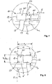
- a side view of the locking unit in the blocking position thereof seen from an inner side of the pullout guide,
- FIG. 7
- an enlarged view of the side view of the locking unit according to
FIG. 6 and - FIG. 8
- an enlarged side view of the locking unit in the release position (viewed from the inner side of the running rail).
Eine Auszugsführung für Möbelteile kann als eine Vollauszugsführung oder als eine Halbauszugsführung ausgebildet sein.A drawer guide for furniture parts can be designed as a full-extension guide or as a half-pull guide.
Im vorliegenden Ausführungsbeispiel wird von einer Halbauszugsführung ausgegangen, die über eine an einen Möbelkorpus festlegbare Korpusschiene 2 verfügt. Die Korpusschiene 2 weist hierzu eine Mehrzahl von Bohrungen 3 auf, über die die Korpusschiene 2 durch Schraubverbindung an dem Möbelkorpus festlegbar ist.In the present embodiment, it is assumed that a half-pull guide, which has a fixable to a furniture body carcass rail 2. For this purpose, the carcass rail 2 has a plurality of bores 3, by way of which the carcass rail 2 can be fixed by screw connection to the furniture carcass.
Ferner umfasst die Auszugsführung eine in Erstreckungsrichtung E der Korpusschiene 2 verlaufende Laufschiene 4, die in üblicherweise an Seitenwänden eines als Schubkasten ausgebildeten Möbelteils 1 festlegbar ist. Die Laufschiene 4 ist in Erstreckungsrichtung E der Korpusschiene 2 verfahrbar zu der Korpusschiene 2 gelagert.Further, the pullout guide comprises a running
Zur Sicherung der Auszugsführung an dem Schubkasten 1 ist eine Sperreinheit 5 vorgesehen, die einstückig aus einem Sperrelement 6, einem Führungselement 7 sowie einem das Sperrelement 6 mit dem Führungselement 7 verbindenden Verbindungselement 8 besteht.To secure the drawer slide to the
Das Sperrelement 6 erstreckt sich außenseitig einer vertikalen Wandung 9 der profilartig ausgebildeten Laufschiene 4, während sich das Führungselement 7 im Wesentlichen auf einer inneren Seite dieser vertikalen Wandung 9 erstreckt.The blocking
Zur Halterung der Sperreinheit 5 an der Laufschiene 4 weist dieselbe ein Langloch 10 auf, das in Erstreckungsrichtung E der Laufschiene 4 verläuft.For holding the
Das Langloch 10 erstreckt sich in einem vorderen Stirnbereich 11 der Laufschiene 4, damit die Sperreinheit 5 für eine Bedienperson leicht zugänglich ist.The
Das Sperrelement 6 weist in einem hinteren Bereich desselben ein seitlich abstehendes Griffteil 12 auf, so dass das Sperrelement 6 bzw. die Sperreinheit 5 einfach manuell verschiebbar ist zwischen einer beispielsweise in
Wie insbesondere aus
Das Führungselement 7 der Sperreinheit 5 ist als eine Führungsplatte ausgebildet. Das Sperrelement 6 der Sperreinheit 5 ist als eine Sperrplatte ausgebildet. Das Verbindungselement 8 der Sperreinheit 5 ist als ein Verbindungssteg ausgebildet. In der Freigabestellung befindet sich die Führungsplatte 7 im Wesentlichen in Höhe des breiten Langlochabschnitts 10'. In der Sperrstellung befindet sich die Führungsplatte 7 im Wesentlichen in Höhe des schmalen Langlochabschnitts 10". In der Sperrstellung verläuft der Verbindungssteg 8 im Wesentlichen in dem schmalen Langlochabschnitt 10". In der Freigabestellung befindet sich der Verbindungssteg 8 teilweise in dem schmalen Langlochabschnitt 10", wie aus
Eine quer zur Erstreckungsrichtung E verlaufende Breite bV des Verbindungselementes 8 ist vorzugsweise kleiner als eine Breite bL2 des schmalen Langlochabschnitts 10", so dass ein Bewegen der Sperreinheit 5 in Erstreckungsrichtung E mit Spiel gewährleistet ist. Ferner ist ein lichter Abstand a1 zwischen der Sperrplatte 6 und der Führungsplatte 7 größer als eine Dicke d der Laufschiene 4 bzw. der vertikalen Wand 9 der Laufschiene 4, so dass das Verschieben der Sperreinheit 5 in Erstreckungsrichtung E mit Spiel gewährleistet ist. Vorzugsweise sind das Sperrelement 6 und das Führungselement 7 so relativ zueinander angeordnet, dass eine selbsthemmende Führung in Erstreckungsrichtung E vorliegt.A transverse to the extending direction E width b V of the connecting element 8 is preferably smaller than a width b of the narrow elongated hole portion so that a movement of the
Zur Führung der Sperreinheit 5 zwischen der Freigabestellung und der Sperrstellung vice versa sind auf einer dem Führungselement 7 zugewandten Flachseite 6' des Sperrelementes 6 zwei Führungshöcker 17 abstehend angeformt. Die Führungshöcker 17 sind in einem hinteren Bereich 18 des Sperrelementes 6 angeordnet, wobei ein Außenabstand aF der beiden Führungshöcker 17 im Wesentlichen einer Breite bL1 des breiten Langlochabschnitts 10' entspricht. Die Führungshöcker 17 liegen in der Freigabestellung an einer rückseitigen Randkante 19 des breiten Langlochabschnitts 10' an, siehe
Eine quer zur Erstreckungsrichtung verlaufende Breite des Sperrelementes und/oder eine quer zur Erstreckungsrichtung verlaufende Breite des Führungselementes ist größer ist als eine Breite des breiten Lochabschnitts.A transverse to the extension direction width of the locking element and / or extending transversely to the extension direction width of the guide element is greater than a width of the wide hole portion.
Die einstückige Sperreinheit 5 besteht aus einem starren Material, insbesondere aus einem starren Kunststoffmaterial. Die Sperreinheit 5 kann als ein Spritzgießteil ausgebildet sein. Zur Montage der Sperreinheit 5 an der Laufschiene 4 wird die Führungsplatte 7 unter Verbiegen desselben relativ zu dem Sperrelement 6 von außen durch den breiten Langlochabschnitt 10' gesteckt. Da ein Abstand a2 zwischen einem vorderen Rand 22 des Führungselementes 7 und einer quer zur Erstreckungsrichtung E und an rückseitigen Flächen der Führungshöcker 17 verlaufenden gedachten Verbindungslinie V größer ist als eine Länge l1 des breiten Langlochabschnitts 10', ist die Sperreinheit 5 unverlierbar an der Laufschiene 4 gehalten. Eine Breite bF der Führungsplatte 7 kann somit kleiner sein als eine Breite bL1 des breiten Langlochabschnitts 10'.The one-
Die Führungshöcker 17 dienen auch als Anschlagteile, da sie in der Freigabestellung gegen die rückseitige Randkante 19 und in der Sperrstellung gegen die vorderseitige Randkante 20 des breiten Langlochabschnitts 10' anschlagen.The guide bumps 17 also serve as stop members, since they abut in the release position against the
Nach einer nicht dargestellten alternativen Ausführungsform der Erfindung kann auch lediglich ein Anschlagteil, beispielsweise mittig in Höhe des Sperrelementes 6, angeordnet sein. Hierbei fehlt jedoch die gewünschte Führung, die der Selbsthemmung entgegenwirkt.According to an alternative embodiment of the invention, not shown, only one stop member, for example, in the middle of the
Die Aufnahme 14 der Frontblende 15 ist vorzugsweise als eine Vertiefung ausgebildet, deren Quererstreckung größer ist als die Quererstreckung der Nase 13. Die Dimension der Vertiefung ist derart an die Nase 13 angepasst, dass diese in der Sperrstellung klemmend in der Vertiefung 14 gehalten ist.The
Nach einer nicht dargestellten alternativen Ausführungsform der Erfindung kann die Sperreinheit 5 in Erstreckungsrichtung E eine Anzahl von Rastmitteln aufweisen, so dass eine rastende Verschiebung der Sperreinheit 5 in Erstreckungsrichtung E während des Verschiebens haptisch erkennbar ist. Zusätzlich können Rastmittel vorgesehen sein, so dass die Sperreinheit 5 in den Endstellungen (Sperrstellung, Freigabestellung) rastend in dem Langloch 10 gehalten ist.According to an alternative embodiment of the invention, not shown, the
Nach einer weiteren Ausführungsform der Erfindung kann die Sperreinheit 5 auch ein Federelement aufweisen, mittels dessen eine in Richtung der Sperrstellung wirkende Federkraft auf das Sperrelement ausgeübt wird. Das Federelement kann sich beispielsweise an der rückseitigen Randkante 19 des breiten Langlochabschnitts 10' abstützen. Vorzugsweise ist das Federelement einstückig mit der Sperreinheit 5 bzw. Sperrelement 6 verbunden.According to a further embodiment of the invention, the
Claims (14)
- A pull-out guide for furniture parts (1), in particular for drawers, having a body rail (2) attachable to a furniture body, having a running rail (4) attachable to a pull-out furniture part (1), wherein the running rail (4) is displaceably mounted in the extension direction (E) of the body rail (2), a locking unit (5) is provided on a front end of the running rail (4), said locking unit having a locking element (6) provided with a nose (13), said locking element being able to, on the one hand, be brought into a locking position by displacement in the extension direction (E) of the running rail (4), in which locking position the nose (13) of the locking element (6) engages in a receptacle (14) of the pull-out furniture part (1) and, on the other hand, being able to be brought into a release position, in which the nose (13) of the locking element (6) does not engage in the receptacle (14) of the pull-out furniture part (1), characterized in that the locking element (6) is integrally connected to a guide element (7), by means of which the locking element (6) is mounted at an elongate hole (10) of the running rail (4) so that it is guided in the extension direction (E) of the same.
- The pull-out guide according to Claim 1, characterized in that the locking element (6) is connected by means of a connecting element (8) to the guide element (7), wherein a width (bv) of the connecting element (7) is smaller than a width (bL2) of the elongate hole (10") and wherein a clear distance (a1) between the guide element (7) and the locking element (6) is larger than a thickness (d) of the running rail (4) such that the locking element (6) is movable with play between the release position and the locking position and vice versa.
- The pull-out guide according to Claim 1 or 2, characterized in that the elongate hole (10) is configured in the manner of a keyhole with a wide hole portion (10') and with a narrow hole portion (10"), wherein the wide hole portion (10') is configured in the manner of a window such that the guide element (7) is pushable through the wide hole portion (10') by bending the locking element (6) so that the locking unit (5) is located in a captive assembly position.
- The pull-out guide according to any one of Claims 1 to 3, characterized in that the connecting element (8) is mounted in the narrow elongate hole portion (10") in a self-retaining manner in the extension direction (E).
- The pull-out guide according to Claim 3 or 4, characterized in that a length of the connecting element (8) running in the extension direction (E) and a length of the guide element (7) are smaller than a length of the narrow hole portion (10").
- The pull-out guide according to any one of Claims 3 to 5, characterized in that a width (bs) of the locking element (6) running transversely to the extension direction (E) and/or a width of the guide element (7) running transversely to the extension direction (E) is/are larger than a width (bL1) of the wide hole portion (10').
- The pull-out guide according to any one of Claims 3 to 6, characterized in that a stop part (17) projects from a flat side (6') of the locking element (6) facing the guide element (7), said stop part abutting in the release position against a marginal edge (19) of the wide hole portion (10') on the back and in the locking position against a marginal edge (20) of the wide hole portion (10') on the front.
- The pull-out guide according to any one of Claims 3 to 7, characterized in that two guide protuberances (17) are provided as stop parts, the outer distance (aF) of which from one another corresponds with the width (bL1) of the wide hole portion (10') so that they move along between the release position and the locking position along a longitudinal marginal edge (21) of the wide hole portion (10') running in the extension direction (E).
- The pull-out guide according to any one of Claims 3 to 8, characterized in that a distance of a front edge (22) of the guide element (7) from a connecting line (V), which connects the guide protuberances (17) on the back to one another, is larger than a length (l1) of the wide elongate hole portion (10').
- The pull-out guide according to any one of Claims 1 to 9, characterized in that the locking unit (5) is formed from a rigid material.
- The pull-out guide according to any one of Claims 1 to 10, characterized in that the locking element (6) has a handle part (12) on a flat side facing away from the guide element (7).
- The pull-out guide according to any one of Claims 1 to 11, characterized in that the guide element (7) and/or the locking element (6) and/or the elongate hole (10) has/have latching means such that the locking element (6) is held in a latching manner in the elongate hole (10) in the locking position.
- The pull-out guide according to any one of Claims 1 to 12, characterized in that the locking unit (5) has a spring element which is integrally connected to the locking element (6) and/or to the guide element (7) such that a spring force acting in the direction of the locking position acts on the locking element (6).
- Furniture having a pull-out guide according to any one of Claims 1 to 13, characterized in that the receptacle (14) of the furniture body (1) is configured as a cavity on a front panel (15) of the pull-out furniture part which is configured as a drawer.
Applications Claiming Priority (1)
| Application Number | Priority Date | Filing Date | Title |
|---|---|---|---|
| DE202016104578.9U DE202016104578U1 (en) | 2016-08-22 | 2016-08-22 | Pull-out guide for furniture parts |
Publications (2)
| Publication Number | Publication Date |
|---|---|
| EP3287042A1 EP3287042A1 (en) | 2018-02-28 |
| EP3287042B1 true EP3287042B1 (en) | 2019-10-09 |
Family
ID=57135457
Family Applications (1)
| Application Number | Title | Priority Date | Filing Date |
|---|---|---|---|
| EP17186575.1A Active EP3287042B1 (en) | 2016-08-22 | 2017-08-17 | Pull-out guide for furniture parts |
Country Status (2)
| Country | Link |
|---|---|
| EP (1) | EP3287042B1 (en) |
| DE (1) | DE202016104578U1 (en) |
Family Cites Families (5)
| Publication number | Priority date | Publication date | Assignee | Title |
|---|---|---|---|---|
| AT398517B (en) * | 1992-12-17 | 1994-12-27 | Blum Gmbh Julius | DRAWER |
| GB2354933A (en) * | 1999-10-07 | 2001-04-11 | Accuride Int Ltd | Drawer with drawer slide quick release mechanism |
| DE202006003035U1 (en) * | 2006-02-25 | 2007-07-05 | Alfit Ag | Device for the adjustable mounting of the running rail of pull-out guides on drawers |
| DE202009003826U1 (en) | 2009-03-20 | 2010-08-12 | Paul Hettich Gmbh & Co. Kg | pull-out guide |
| DE202009013830U1 (en) | 2009-10-12 | 2011-02-24 | "REME-Möbelbeschläge GmbH" | Device for releasably securing an extract, drawer, or the like on a guide rail |
-
2016
- 2016-08-22 DE DE202016104578.9U patent/DE202016104578U1/en not_active Expired - Lifetime
-
2017
- 2017-08-17 EP EP17186575.1A patent/EP3287042B1/en active Active
Non-Patent Citations (1)
| Title |
|---|
| None * |
Also Published As
| Publication number | Publication date |
|---|---|
| DE202016104578U1 (en) | 2016-09-22 |
| EP3287042A1 (en) | 2018-02-28 |
Similar Documents
| Publication | Publication Date | Title |
|---|---|---|
| EP3291704B1 (en) | Furniture and method for fixing a drawer | |
| EP3291706B1 (en) | Furniture and method for fixing a movable furniture part | |
| EP2222202B1 (en) | Drawer with front-adjustment | |
| EP3291705B1 (en) | Furniture with drawer and method for fixing a drawer | |
| EP2959802B1 (en) | Device for applying a guide unit to a piece of furniture | |
| EP2994011B1 (en) | Drawer slide | |
| EP3291702B1 (en) | Piece of furniture and method for fixing a drawer | |
| AT509415B1 (en) | Arrangement with a drawer and a pull-out guide for a drawer with at least two latching positions | |
| EP2704604B1 (en) | Drawer | |
| AT511906A1 (en) | DRAWER | |
| AT506543A1 (en) | FIXING DEVICE FOR LOCKING A FURNITURE MOVED IN OR ON A FURNITURE | |
| EP3684223B1 (en) | Coupling device for drawer with subsequent latching | |
| EP3147435A1 (en) | Pull-out locking device and piece of furniture | |
| WO2012110373A1 (en) | Device for locking parts which can be moved relative to one another | |
| EP1865135B1 (en) | Guide for sliding door fitting | |
| AT515689B1 (en) | drawer | |
| EP2951374B1 (en) | Running part for guiding a furniture part in a guiding direction via a guiding rail, and furniture fitting | |
| EP3166444B1 (en) | Pull-out guide for a movable furniture part | |
| WO2010037683A1 (en) | Furniture pull-out guide | |
| EP3287042B1 (en) | Pull-out guide for furniture parts | |
| DE202015100014U1 (en) | Locking device of a double-sided pull-out drawer cabinet | |
| DE102015111998A1 (en) | Rail arrangement, cabinet furniture and method for mounting a guide rail | |
| EP3025938B1 (en) | Covering device for a flat side of a wall element | |
| DE202013004939U1 (en) | Device for positioning and fixing a movable furniture part | |
| DE102017128049A1 (en) | Pull-out devices for drawers and the like |
Legal Events
| Date | Code | Title | Description |
|---|---|---|---|
| PUAI | Public reference made under article 153(3) epc to a published international application that has entered the european phase |
Free format text: ORIGINAL CODE: 0009012 |
|
| STAA | Information on the status of an ep patent application or granted ep patent |
Free format text: STATUS: THE APPLICATION HAS BEEN PUBLISHED |
|
| AK | Designated contracting states |
Kind code of ref document: A1 Designated state(s): AL AT BE BG CH CY CZ DE DK EE ES FI FR GB GR HR HU IE IS IT LI LT LU LV MC MK MT NL NO PL PT RO RS SE SI SK SM TR |
|
| AX | Request for extension of the european patent |
Extension state: BA ME |
|
| STAA | Information on the status of an ep patent application or granted ep patent |
Free format text: STATUS: REQUEST FOR EXAMINATION WAS MADE |
|
| 17P | Request for examination filed |
Effective date: 20180802 |
|
| RBV | Designated contracting states (corrected) |
Designated state(s): AL AT BE BG CH CY CZ DE DK EE ES FI FR GB GR HR HU IE IS IT LI LT LU LV MC MK MT NL NO PL PT RO RS SE SI SK SM TR |
|
| GRAP | Despatch of communication of intention to grant a patent |
Free format text: ORIGINAL CODE: EPIDOSNIGR1 |
|
| STAA | Information on the status of an ep patent application or granted ep patent |
Free format text: STATUS: GRANT OF PATENT IS INTENDED |
|
| INTG | Intention to grant announced |
Effective date: 20190627 |
|
| GRAS | Grant fee paid |
Free format text: ORIGINAL CODE: EPIDOSNIGR3 |
|
| GRAA | (expected) grant |
Free format text: ORIGINAL CODE: 0009210 |
|
| STAA | Information on the status of an ep patent application or granted ep patent |
Free format text: STATUS: THE PATENT HAS BEEN GRANTED |
|
| AK | Designated contracting states |
Kind code of ref document: B1 Designated state(s): AL AT BE BG CH CY CZ DE DK EE ES FI FR GB GR HR HU IE IS IT LI LT LU LV MC MK MT NL NO PL PT RO RS SE SI SK SM TR |
|
| REG | Reference to a national code |
Ref country code: GB Ref legal event code: FG4D Free format text: NOT ENGLISH |
|
| REG | Reference to a national code |
Ref country code: CH Ref legal event code: EP |
|
| REG | Reference to a national code |
Ref country code: DE Ref legal event code: R096 Ref document number: 502017002509 Country of ref document: DE |
|
| REG | Reference to a national code |
Ref country code: IE Ref legal event code: FG4D Free format text: LANGUAGE OF EP DOCUMENT: GERMAN |
|
| REG | Reference to a national code |
Ref country code: AT Ref legal event code: REF Ref document number: 1187780 Country of ref document: AT Kind code of ref document: T Effective date: 20191115 |
|
| REG | Reference to a national code |
Ref country code: NL Ref legal event code: MP Effective date: 20191009 |
|
| REG | Reference to a national code |
Ref country code: LT Ref legal event code: MG4D |
|
| PG25 | Lapsed in a contracting state [announced via postgrant information from national office to epo] |
Ref country code: FI Free format text: LAPSE BECAUSE OF FAILURE TO SUBMIT A TRANSLATION OF THE DESCRIPTION OR TO PAY THE FEE WITHIN THE PRESCRIBED TIME-LIMIT Effective date: 20191009 Ref country code: LV Free format text: LAPSE BECAUSE OF FAILURE TO SUBMIT A TRANSLATION OF THE DESCRIPTION OR TO PAY THE FEE WITHIN THE PRESCRIBED TIME-LIMIT Effective date: 20191009 Ref country code: SE Free format text: LAPSE BECAUSE OF FAILURE TO SUBMIT A TRANSLATION OF THE DESCRIPTION OR TO PAY THE FEE WITHIN THE PRESCRIBED TIME-LIMIT Effective date: 20191009 Ref country code: GR Free format text: LAPSE BECAUSE OF FAILURE TO SUBMIT A TRANSLATION OF THE DESCRIPTION OR TO PAY THE FEE WITHIN THE PRESCRIBED TIME-LIMIT Effective date: 20200110 Ref country code: ES Free format text: LAPSE BECAUSE OF FAILURE TO SUBMIT A TRANSLATION OF THE DESCRIPTION OR TO PAY THE FEE WITHIN THE PRESCRIBED TIME-LIMIT Effective date: 20191009 Ref country code: NL Free format text: LAPSE BECAUSE OF FAILURE TO SUBMIT A TRANSLATION OF THE DESCRIPTION OR TO PAY THE FEE WITHIN THE PRESCRIBED TIME-LIMIT Effective date: 20191009 Ref country code: PT Free format text: LAPSE BECAUSE OF FAILURE TO SUBMIT A TRANSLATION OF THE DESCRIPTION OR TO PAY THE FEE WITHIN THE PRESCRIBED TIME-LIMIT Effective date: 20200210 Ref country code: LT Free format text: LAPSE BECAUSE OF FAILURE TO SUBMIT A TRANSLATION OF THE DESCRIPTION OR TO PAY THE FEE WITHIN THE PRESCRIBED TIME-LIMIT Effective date: 20191009 Ref country code: PL Free format text: LAPSE BECAUSE OF FAILURE TO SUBMIT A TRANSLATION OF THE DESCRIPTION OR TO PAY THE FEE WITHIN THE PRESCRIBED TIME-LIMIT Effective date: 20191009 Ref country code: NO Free format text: LAPSE BECAUSE OF FAILURE TO SUBMIT A TRANSLATION OF THE DESCRIPTION OR TO PAY THE FEE WITHIN THE PRESCRIBED TIME-LIMIT Effective date: 20200109 Ref country code: BG Free format text: LAPSE BECAUSE OF FAILURE TO SUBMIT A TRANSLATION OF THE DESCRIPTION OR TO PAY THE FEE WITHIN THE PRESCRIBED TIME-LIMIT Effective date: 20200109 |
|
| PG25 | Lapsed in a contracting state [announced via postgrant information from national office to epo] |
Ref country code: IS Free format text: LAPSE BECAUSE OF FAILURE TO SUBMIT A TRANSLATION OF THE DESCRIPTION OR TO PAY THE FEE WITHIN THE PRESCRIBED TIME-LIMIT Effective date: 20200224 Ref country code: HR Free format text: LAPSE BECAUSE OF FAILURE TO SUBMIT A TRANSLATION OF THE DESCRIPTION OR TO PAY THE FEE WITHIN THE PRESCRIBED TIME-LIMIT Effective date: 20191009 Ref country code: RS Free format text: LAPSE BECAUSE OF FAILURE TO SUBMIT A TRANSLATION OF THE DESCRIPTION OR TO PAY THE FEE WITHIN THE PRESCRIBED TIME-LIMIT Effective date: 20191009 |
|
| PG25 | Lapsed in a contracting state [announced via postgrant information from national office to epo] |
Ref country code: AL Free format text: LAPSE BECAUSE OF FAILURE TO SUBMIT A TRANSLATION OF THE DESCRIPTION OR TO PAY THE FEE WITHIN THE PRESCRIBED TIME-LIMIT Effective date: 20191009 |
|
| REG | Reference to a national code |
Ref country code: DE Ref legal event code: R097 Ref document number: 502017002509 Country of ref document: DE |
|
| PG2D | Information on lapse in contracting state deleted |
Ref country code: IS |
|
| PG25 | Lapsed in a contracting state [announced via postgrant information from national office to epo] |
Ref country code: IS Free format text: LAPSE BECAUSE OF FAILURE TO SUBMIT A TRANSLATION OF THE DESCRIPTION OR TO PAY THE FEE WITHIN THE PRESCRIBED TIME-LIMIT Effective date: 20200209 Ref country code: RO Free format text: LAPSE BECAUSE OF FAILURE TO SUBMIT A TRANSLATION OF THE DESCRIPTION OR TO PAY THE FEE WITHIN THE PRESCRIBED TIME-LIMIT Effective date: 20191009 Ref country code: CZ Free format text: LAPSE BECAUSE OF FAILURE TO SUBMIT A TRANSLATION OF THE DESCRIPTION OR TO PAY THE FEE WITHIN THE PRESCRIBED TIME-LIMIT Effective date: 20191009 Ref country code: EE Free format text: LAPSE BECAUSE OF FAILURE TO SUBMIT A TRANSLATION OF THE DESCRIPTION OR TO PAY THE FEE WITHIN THE PRESCRIBED TIME-LIMIT Effective date: 20191009 Ref country code: DK Free format text: LAPSE BECAUSE OF FAILURE TO SUBMIT A TRANSLATION OF THE DESCRIPTION OR TO PAY THE FEE WITHIN THE PRESCRIBED TIME-LIMIT Effective date: 20191009 |
|
| PLBE | No opposition filed within time limit |
Free format text: ORIGINAL CODE: 0009261 |
|
| STAA | Information on the status of an ep patent application or granted ep patent |
Free format text: STATUS: NO OPPOSITION FILED WITHIN TIME LIMIT |
|
| PG25 | Lapsed in a contracting state [announced via postgrant information from national office to epo] |
Ref country code: IT Free format text: LAPSE BECAUSE OF FAILURE TO SUBMIT A TRANSLATION OF THE DESCRIPTION OR TO PAY THE FEE WITHIN THE PRESCRIBED TIME-LIMIT Effective date: 20191009 Ref country code: SM Free format text: LAPSE BECAUSE OF FAILURE TO SUBMIT A TRANSLATION OF THE DESCRIPTION OR TO PAY THE FEE WITHIN THE PRESCRIBED TIME-LIMIT Effective date: 20191009 Ref country code: SK Free format text: LAPSE BECAUSE OF FAILURE TO SUBMIT A TRANSLATION OF THE DESCRIPTION OR TO PAY THE FEE WITHIN THE PRESCRIBED TIME-LIMIT Effective date: 20191009 |
|
| 26N | No opposition filed |
Effective date: 20200710 |
|
| PG25 | Lapsed in a contracting state [announced via postgrant information from national office to epo] |
Ref country code: SI Free format text: LAPSE BECAUSE OF FAILURE TO SUBMIT A TRANSLATION OF THE DESCRIPTION OR TO PAY THE FEE WITHIN THE PRESCRIBED TIME-LIMIT Effective date: 20191009 |
|
| PG25 | Lapsed in a contracting state [announced via postgrant information from national office to epo] |
Ref country code: MC Free format text: LAPSE BECAUSE OF FAILURE TO SUBMIT A TRANSLATION OF THE DESCRIPTION OR TO PAY THE FEE WITHIN THE PRESCRIBED TIME-LIMIT Effective date: 20191009 |
|
| REG | Reference to a national code |
Ref country code: CH Ref legal event code: PL |
|
| PG25 | Lapsed in a contracting state [announced via postgrant information from national office to epo] |
Ref country code: LU Free format text: LAPSE BECAUSE OF NON-PAYMENT OF DUE FEES Effective date: 20200817 Ref country code: LI Free format text: LAPSE BECAUSE OF NON-PAYMENT OF DUE FEES Effective date: 20200831 Ref country code: CH Free format text: LAPSE BECAUSE OF NON-PAYMENT OF DUE FEES Effective date: 20200831 |
|
| REG | Reference to a national code |
Ref country code: BE Ref legal event code: MM Effective date: 20200831 |
|
| PG25 | Lapsed in a contracting state [announced via postgrant information from national office to epo] |
Ref country code: FR Free format text: LAPSE BECAUSE OF NON-PAYMENT OF DUE FEES Effective date: 20200831 |
|
| PG25 | Lapsed in a contracting state [announced via postgrant information from national office to epo] |
Ref country code: IE Free format text: LAPSE BECAUSE OF NON-PAYMENT OF DUE FEES Effective date: 20200817 Ref country code: BE Free format text: LAPSE BECAUSE OF NON-PAYMENT OF DUE FEES Effective date: 20200831 |
|
| REG | Reference to a national code |
Ref country code: DE Ref legal event code: R082 Ref document number: 502017002509 Country of ref document: DE Representative=s name: ANWALTSKANZLEI EIKEL & PARTNER GBR, DE |
|
| GBPC | Gb: european patent ceased through non-payment of renewal fee |
Effective date: 20210817 |
|
| PG25 | Lapsed in a contracting state [announced via postgrant information from national office to epo] |
Ref country code: TR Free format text: LAPSE BECAUSE OF FAILURE TO SUBMIT A TRANSLATION OF THE DESCRIPTION OR TO PAY THE FEE WITHIN THE PRESCRIBED TIME-LIMIT Effective date: 20191009 Ref country code: MT Free format text: LAPSE BECAUSE OF FAILURE TO SUBMIT A TRANSLATION OF THE DESCRIPTION OR TO PAY THE FEE WITHIN THE PRESCRIBED TIME-LIMIT Effective date: 20191009 Ref country code: CY Free format text: LAPSE BECAUSE OF FAILURE TO SUBMIT A TRANSLATION OF THE DESCRIPTION OR TO PAY THE FEE WITHIN THE PRESCRIBED TIME-LIMIT Effective date: 20191009 |
|
| PG25 | Lapsed in a contracting state [announced via postgrant information from national office to epo] |
Ref country code: MK Free format text: LAPSE BECAUSE OF FAILURE TO SUBMIT A TRANSLATION OF THE DESCRIPTION OR TO PAY THE FEE WITHIN THE PRESCRIBED TIME-LIMIT Effective date: 20191009 |
|
| PG25 | Lapsed in a contracting state [announced via postgrant information from national office to epo] |
Ref country code: GB Free format text: LAPSE BECAUSE OF NON-PAYMENT OF DUE FEES Effective date: 20210817 |
|
| PGFP | Annual fee paid to national office [announced via postgrant information from national office to epo] |
Ref country code: DE Payment date: 20220603 Year of fee payment: 6 |
|
| REG | Reference to a national code |
Ref country code: AT Ref legal event code: MM01 Ref document number: 1187780 Country of ref document: AT Kind code of ref document: T Effective date: 20220817 |
|
| PG25 | Lapsed in a contracting state [announced via postgrant information from national office to epo] |
Ref country code: AT Free format text: LAPSE BECAUSE OF NON-PAYMENT OF DUE FEES Effective date: 20220817 |
|
| REG | Reference to a national code |
Ref country code: DE Ref legal event code: R119 Ref document number: 502017002509 Country of ref document: DE |
|
| PG25 | Lapsed in a contracting state [announced via postgrant information from national office to epo] |
Ref country code: DE Free format text: LAPSE BECAUSE OF NON-PAYMENT OF DUE FEES Effective date: 20240301 |