EP3632836A1 - Crane with a winch assembly - Google Patents
Crane with a winch assembly Download PDFInfo
- Publication number
- EP3632836A1 EP3632836A1 EP19210979.1A EP19210979A EP3632836A1 EP 3632836 A1 EP3632836 A1 EP 3632836A1 EP 19210979 A EP19210979 A EP 19210979A EP 3632836 A1 EP3632836 A1 EP 3632836A1
- Authority
- EP
- European Patent Office
- Prior art keywords
- spindle
- drum
- rope
- cable
- crane
- Prior art date
- Legal status (The legal status is an assumption and is not a legal conclusion. Google has not performed a legal analysis and makes no representation as to the accuracy of the status listed.)
- Withdrawn
Links
- 238000004804 winding Methods 0.000 claims abstract description 12
- 230000005540 biological transmission Effects 0.000 claims description 8
- 239000000725 suspension Substances 0.000 claims description 7
- 238000006073 displacement reaction Methods 0.000 description 10
- 238000010276 construction Methods 0.000 description 2
- 238000004873 anchoring Methods 0.000 description 1
- 238000012986 modification Methods 0.000 description 1
- 230000004048 modification Effects 0.000 description 1
- 238000005096 rolling process Methods 0.000 description 1
- 238000004904 shortening Methods 0.000 description 1
- 230000001360 synchronised effect Effects 0.000 description 1
Images


Classifications
-
- B—PERFORMING OPERATIONS; TRANSPORTING
- B66—HOISTING; LIFTING; HAULING
- B66D—CAPSTANS; WINCHES; TACKLES, e.g. PULLEY BLOCKS; HOISTS
- B66D1/00—Rope, cable, or chain winding mechanisms; Capstans
- B66D1/28—Other constructional details
- B66D1/36—Guiding, or otherwise ensuring winding in an orderly manner, of ropes, cables, or chains
- B66D1/39—Guiding, or otherwise ensuring winding in an orderly manner, of ropes, cables, or chains by means of axially-movable drums or barrels
-
- B08B1/10—
-
- B08B1/30—
-
- B—PERFORMING OPERATIONS; TRANSPORTING
- B66—HOISTING; LIFTING; HAULING
- B66C—CRANES; LOAD-ENGAGING ELEMENTS OR DEVICES FOR CRANES, CAPSTANS, WINCHES, OR TACKLES
- B66C11/00—Trolleys or crabs, e.g. operating above runways
- B66C11/16—Rope, cable, or chain drives for trolleys; Combinations of such drives with hoisting gear
-
- B—PERFORMING OPERATIONS; TRANSPORTING
- B66—HOISTING; LIFTING; HAULING
- B66C—CRANES; LOAD-ENGAGING ELEMENTS OR DEVICES FOR CRANES, CAPSTANS, WINCHES, OR TACKLES
- B66C19/00—Cranes comprising trolleys or crabs running on fixed or movable bridges or gantries
-
- B—PERFORMING OPERATIONS; TRANSPORTING
- B66—HOISTING; LIFTING; HAULING
- B66C—CRANES; LOAD-ENGAGING ELEMENTS OR DEVICES FOR CRANES, CAPSTANS, WINCHES, OR TACKLES
- B66C19/00—Cranes comprising trolleys or crabs running on fixed or movable bridges or gantries
- B66C19/002—Container cranes
-
- B—PERFORMING OPERATIONS; TRANSPORTING
- B66—HOISTING; LIFTING; HAULING
- B66C—CRANES; LOAD-ENGAGING ELEMENTS OR DEVICES FOR CRANES, CAPSTANS, WINCHES, OR TACKLES
- B66C19/00—Cranes comprising trolleys or crabs running on fixed or movable bridges or gantries
- B66C19/007—Cranes comprising trolleys or crabs running on fixed or movable bridges or gantries for containers
-
- E—FIXED CONSTRUCTIONS
- E02—HYDRAULIC ENGINEERING; FOUNDATIONS; SOIL SHIFTING
- E02B—HYDRAULIC ENGINEERING
- E02B8/00—Details of barrages or weirs ; Energy dissipating devices carried by lock or dry-dock gates
- E02B8/02—Sediment base gates; Sand sluices; Structures for retaining arresting waterborne material
- E02B8/023—Arresting devices for waterborne materials
- E02B8/026—Cleaning devices
-
- E—FIXED CONSTRUCTIONS
- E02—HYDRAULIC ENGINEERING; FOUNDATIONS; SOIL SHIFTING
- E02B—HYDRAULIC ENGINEERING
- E02B9/00—Water-power plants; Layout, construction or equipment, methods of, or apparatus for, making same
-
- B—PERFORMING OPERATIONS; TRANSPORTING
- B66—HOISTING; LIFTING; HAULING
- B66C—CRANES; LOAD-ENGAGING ELEMENTS OR DEVICES FOR CRANES, CAPSTANS, WINCHES, OR TACKLES
- B66C2700/00—Cranes
- B66C2700/01—General aspects of mobile cranes, overhead travelling cranes, gantry cranes, loading bridges, cranes for building ships on slipways, cranes for foundries or cranes for public works
- B66C2700/012—Trolleys or runways
-
- Y—GENERAL TAGGING OF NEW TECHNOLOGICAL DEVELOPMENTS; GENERAL TAGGING OF CROSS-SECTIONAL TECHNOLOGIES SPANNING OVER SEVERAL SECTIONS OF THE IPC; TECHNICAL SUBJECTS COVERED BY FORMER USPC CROSS-REFERENCE ART COLLECTIONS [XRACs] AND DIGESTS
- Y02—TECHNOLOGIES OR APPLICATIONS FOR MITIGATION OR ADAPTATION AGAINST CLIMATE CHANGE
- Y02E—REDUCTION OF GREENHOUSE GAS [GHG] EMISSIONS, RELATED TO ENERGY GENERATION, TRANSMISSION OR DISTRIBUTION
- Y02E10/00—Energy generation through renewable energy sources
- Y02E10/20—Hydro energy
Definitions
- the present invention relates to a crane, in particular a gantry crane, for transporting at least one container or another load, the crane having at least one trolley mounted on a crane girder of the crane and a load suspension device for connection to the container or other load, wherein the load suspension device can be lifted and lowered on the trolley by means of ropes of the trolley, and the trolley has at least one winch arrangement for winding and / or unwinding the ropes of the trolley, the winch arrangement having at least one rope drum rotatably mounted about a drum axis for opening and / or or unwinding at least one of the ropes and comprising a support structure and a spindle drive for displacing the cable drum relative to the support structure, the spindle drive having a spindle extending along a spindle axis, and a rope run-off point of the at least one rope on which the rope is tangential from the side oil drum runs up and / or runs off, based on the support structure, is at least essentially stationary,
- Cable winch arrangements are used in various embodiments for winding and / or unwinding at least one cable, the at least one cable usually being wound onto and / or unwound from the cable drum on a circular cylindrical cable drum, which is also called a winch.
- the at least one rope is usually spiral, in particular helical or helical, can be wound or wound on the rope drum. It is characteristic of common rope winch arrangements that the rope run-off point of the at least one rope, on which the rope runs tangentially onto or from the rope drum, is variable in position. That is, the rope run-off point moves along a direction parallel to the drum axis of the rope drum during the winding or unwinding of the rope.
- This movement could also be called “walking" the rope drain point on a drum jacket of the rope drum during the Describe the twist of the rope drum.
- the "wandering" of the rope drain point along the drum jacket of the rope drum means that a freely hanging rope end of a rope partially wound on the rope drum, to which, for example, a load is attached, is moved with the rope drain point parallel to the drum axis, which is why it is moved during the lifting or lowering movement of the rope also results in a mostly undesirable, superimposed displacement of the load in a direction parallel to the drum axis.
- Rope pulleys are often used to steer the at least one rope running off the rope drum in a predetermined direction.
- Rope pulleys have a circumferential rope groove in which the rope is guided.
- An essential parameter of a rope pulley is the lateral run-on angle of the rope when the rope runs in or out of the rope groove of the rope pulley.
- the lateral run-on angle is the angle of the lateral deflection of the rope with respect to a groove plane in which the rope groove of the rope pulley is arranged.
- a large side run-on angle, e.g. more than 4 °, has a significant impact on the lifespan of the rope.
- rope pulleys In order to limit the lateral run-on angle, rope pulleys must therefore be arranged at a relatively large distance from the rope drum.
- the document DE 101 35 034 C1 discloses a cable winch arrangement for a traveling crane with a displacement unit, which longitudinally displaces the cable drum in synchronism with the winding and unwinding of the cables in such a way that the respective cable run-off points, based on a hoist frame, are always in the same place. As a result, the lateral run-on angle of the rope on the respective rope pulley can be kept constant.
- the displacement unit has a threaded spindle drive for displacing the cable drum, the threaded spindle drive being coupled to the cable drum axis via a toothed belt.
- the object of the invention is to provide an advantageous crane of the type mentioned at the outset, which can be designed in a simple manner.
- the spindle axis is arranged coaxially with the drum axis of the cable drum. This means that the spindle axis lies on a common axis with the drum axis of the cable drum. This allows a simple construction of the winch arrangement of the crane to be realized.
- the spindle drive is a screw gear.
- the spindle drive according to the invention can be a trapezoidal screw drive, ball screw drive, roller screw drive with roller return, planetary roller screw drive, steep screw drive etc.
- the spindle drive connects the support structure to the cable drum, an adjustment of the spindle drive leading to a relative displacement of the cable drum with respect to the support structure.
- the spindle drive is adjusted in the direction of the spindle axis. Since the drum axis of the cable drum is arranged coaxially with the spindle axis, the relative displacement of the cable drum with respect to the support structure also takes place in a direction parallel to the drum axis or to the spindle axis.
- the rope run-off point is "at least essentially stationary” it is meant that the rope run-off point is at least essentially immovable with respect to the support structure during the winding or unwinding of the rope.
- the point at which the rope runs off is, in particular, the point at which a longitudinal center axis of the rope changes from a helical orientation - which a section of the rope wound on the rope drum takes up - into a tangential direction - in relation to the drum jacket of the rope drum.
- the rope run-off point could also be referred to as a rope run-up point or as a rope run-up and run-off point.
- the expression “at least essentially” means that the rope run-off point between a completely unwound state of the rope and a completely wound state of the rope advantageously moves parallel to the drum axis by less than the amount of a rope diameter.
- the term support structure is to be understood broadly in the sense of the invention.
- the supporting structure can, for example, be a supporting component of a trolley of the crane.
- the support structure serves to support the cable drum and to absorb the cable forces acting on the cable drum.
- the cable drum can be supported on the supporting structure or can be connected to the supporting structure in some other way. For example, it is also conceivable and possible for the cable drum to hang on the support structure.
- the cable drum is advantageously rotatably mounted on a storage rack.
- the storage rack could also be called a support frame or drum frame. It is advantageously provided that, apart from the rotation of the rotatably mounted cable drum, no relative movement between the cable drum and the storage frame is possible. I.e. that the storage rack can advantageously be moved together with the cable drum relative to the support structure.
- the cable winch arrangement can have a sliding guide or a roller guide.
- the spindle at least in one end position, extends at least in sections into a cavity of the cable drum.
- a particularly compact design of the cable winch arrangement can thereby be realized.
- the cable winch arrangement advantageously has two end positions, the end positions limiting the travel of the cable drum relative to the support structure, in mutually opposite directions aligned parallel to the spindle axis or to the drum axis.
- the cavity of the cable drum could be completely delimited in the radial direction with respect to the drum axis by a drum jacket of the cable drum. Furthermore, the cable drum could have two mutually opposite drum flanges, which refer to the cavity in the axial direction limit the drum axis.
- the spindle of the spindle drive is arranged in one of the end positions over at least 50%, preferably at least 70%, of the length of the spindle in the cavity of the cable drum.
- the spindle has an external thread with a pitch, the pitch of the external thread corresponding at least to the rope diameter of the at least one rope.
- the pitch refers to the distance between two threads in a direction parallel to the spindle axis.
- the pitch gives the measure of the adjustment of a spindle nut of the spindle drive in relation to a direction parallel to the spindle axis when the spindle nut is rotated relative to the spindle by 360 °, i.e. by one turn.
- the rope diameter means the outside diameter of the rope.
- a rope viewed in a cross section orthogonal to the longitudinal center axis of the rope, often has a cross section deviating from the circle.
- the diameter of a smallest circumference encompassing the cross section of the rope could also be referred to as the rope diameter.
- the cable drum has a drum jacket with at least one spiral groove for receiving at least one of the cables, a pitch of the spiral groove corresponding to the pitch of the external thread of the spindle.
- the at least one spiral groove of the drum shell advantageously extends helically along the drum axis, in particular around the drum axis.
- the at least one groove of the drum shell could also be referred to as helical or helical.
- the at least one groove can extend helically over the entire longitudinal extent of the drum shell.
- the drum shell it is also conceivable and possible for the drum shell to have a plurality of grooves which, based on the direction of the drum axis, can be arranged one behind the other and at a distance from one another.
- the spiral grooves are interleaved, ie that the pitch of each spiral groove is greater than the rope diameter of the at least one rope.
- the pitch could be an integral multiple of the rope diameter.
- the entirety of the grooves of the drum shell could also be referred to as multi-start grooving.
- an outer surface of the drum shell could be designed in the form of a circular cylinder shell, ie essentially smooth. This means that a grooved drum jacket is then dispensed with.
- the spindle in a possible embodiment according to the invention, provision could be made for the spindle to be fixed in a rotationally fixed manner and, at least in the axial direction with respect to the spindle axis, to be fixed on the support structure. It is then particularly preferably provided that the spindle is fixed to the support structure, i.e. that all degrees of freedom of the spindle are locked in relation to the supporting structure.
- the spindle drive has a transmission gear for transmitting a rotary movement of the cable drum to a spindle nut of the spindle drive which engages in the spindle. This makes it possible to use a spindle with an external thread, which has a pitch that is less than the amount of the rope diameter of the at least one rope.
- the spindle nut of the spindle drive which engages in the spindle, to be fastened or fastened to the cable drum in a rotationally fixed manner. In this embodiment it is therefore provided that the rotary movement of the cable drum is transmitted directly to the spindle nut.
- the spindle nut engaging in the spindle can be fastened or fastened to the bearing frame of the cable drum in a rotationally fixed manner.
- the spindle drive has a spindle drive for rotating the spindle relative to the supporting structure.
- the rope drum can be moved entirely by means of the spindle drive, in particular when the spindle nut is fastened to the bearing frame.
- the cable drum rotation movement it would also be conceivable for the cable drum rotation movement to be superimposed on the rotation of the spindle of the spindle drive during operation.
- the rope outlet point of the at least one rope is, at least essentially, stationary with respect to the support structure.
- a separate winch arrangement is provided for each rope of the trolley. It is particularly preferred if several ropes, e.g. four ropes, can be wound on a common rope drum.
- the grooves for receiving a respective cable can be arranged one behind the other in relation to the direction of the drum axis, i.e. spaced apart. Variants of rope drums with multi-start grooves are also conceivable and possible.
- the cable winch arrangement 1 has a cable drum 2 for winding and / or unwinding a cable 30 and a storage frame 8 for the rotatable mounting of the cable drum 2 rotatable about a drum axis 3.
- the storage of the cable drum 2 on the storage rack 8, for example with rolling bearings, is shown in FIGS Figures 1 and 2 not shown separately. Such arrangements are, however, generally known in a variety of embodiments.
- the cable drum 2 has a drum jacket 4 and two drum flanges 7 which, in the axial direction with respect to the drum axis 3 on opposite sides, connect to the drum jacket 4.
- a cavity 5 is formed, which, in the radial direction with respect to the drum axis 3, is delimited by the drum jacket 4.
- the cavity 5 is delimited by the drum flanges 7.
- the drum casing 4 has a spiral groove 10 for receiving the cable 30.
- the spiral groove 10 is helical, i. H. in the manner of a helix extending along the drum axis 3.
- the groove 10 could also be referred to as scoring.
- the pitch of the spiral groove 10 corresponds to the rope diameter of the rope 30.
- the pitch of the groove 10 could also have a pitch that is greater than the rope diameter of the rope 30, that is to say that the turns of the rope on the drum jacket 4 wound portion of the rope 30 are spaced apart.
- the drum jacket 4 of the cable drum 2 could also be designed without grooves in other design variants. That is, the outer surface of the drum shell 4 could, for example, be circular cylindrical, i.e. be smooth, educated.
- the cable winch arrangement 1 also has a drum drive 9 for rotating the cable drum 2 about the drum axis 3 relative to the storage rack 8.
- the drum drive 9 can be a geared motor.
- the bearing frame 8 is supported on a support structure 20 by means of support rollers 22 of the cable winch arrangement 1.
- the support rollers 22 facilitate the relative movement of the storage rack 8 and thus the cable drum 2 with respect to the support structure 20.
- support rollers 22 instead of support rollers 22, skids or the like could also be used.
- the support structure 20 is in the 1 and 2 only shown schematically to illustrate the principle of the winch assembly 1 according to the invention. In connection with the still to be explained application examples of the cable winch arrangement 1 according to the invention, possible design variants of the support structure 20 are discussed.
- the support structure 20 has in in the 1 and 2 Embodiment shown a rope passage 21 through which the rope 30 is threaded. However, a rope passage 21 is not mandatory.
- the cable winch arrangement 1 has a spindle drive 14 for displacing the cable drum 2 relative to the support structure 20.
- the spindle drive 14 comprises a spindle 16 extending along a spindle axis 15 and a spindle nut 17 which engages in the spindle 16.
- the spindle drive 14 connects the support structure 20 to the cable drum 2.
- the spindle axis 15 of the spindle drive 14 is arranged coaxially to the drum axis 3 of the cable drum 2.
- the spindle 16 is fixed against rotation and immovable on the support structure 20 in the axial direction with respect to the spindle axis 15.
- the spindle 16 is also immovably fixed to the support structure 20 in all directions orthogonal to the spindle axis 15.
- the spindle nut 17 is fastened to the cable drum 2 in a rotationally fixed manner. A rotation of the cable drum 2 by means of the drum drive 9 therefore leads to a corresponding rotation of the spindle nut 17.
- the cable winch arrangement 1 has two end positions that determine the displacement path of the spindle nut 17 relative to the spindle 16 limit. Overall, the cable drum 2 can thus also be displaced relative to the support structure 20 between the first end position and the second end position of the cable winch arrangement 1.
- the first exemplary embodiment thus provides that the bearing frame 8 together with the cable drum 2 and the spindle nut 17 and the drum drive 9 along the drum axis 3 relative to the support structure 20 is movable.
- the spindle drive 14 is designed as a trapezoidal screw drive. That is, the spindle nut 17 has a trapezoidal internal thread and the spindle 16 has a trapezoidal external thread, which interlock.
- Other variants of spindle drives are also conceivable and possible, as already mentioned at the beginning.
- the spindle drive 14 could also be a flat-screw drive.
- the pitch of the spiral groove 10 corresponds to a pitch of the external thread of the spindle 16.
- This can ensure that a cable outlet point 6 of the cable 30 on which the Rope 30 runs up and / or runs off tangentially from the rope drum 2, based on the support structure 20, is at least essentially stationary. Since the pitch of the external thread of the spindle 16 in the first exemplary embodiment corresponds to the pitch of the spiral groove 10 of the drum casing 4, it is thus necessarily ensured that the rope drain point 6 is always stationary with respect to the support structure 20.
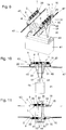
- Fig. 1 the cable drum 2 is shown in the first end position of the cable winch arrangement 1, in which the cable 30 is unwound from the cable drum 2, apart from a remaining length which is wound on the cable drum 2.
- Fig. 2 the second end position is shown, in which the rope 30 is maximally wound on the rope drum 2.
- the rope run-off point 6 is stationary, ie immobile, with respect to the support structure 20. This ensures that the cable 30 can run through the cable passage 21 regardless of the length of the section of the cable 30 wound on the cable drum 2.
- the spindle 16 in particular a section of the spindle 16 having the external thread, is in the second end position, cf. Fig. 2 , extends into the cavity 5 of the cable drum 2 over at least 70% of the longitudinal extent of the spindle 16, in particular the longitudinal extent of the external thread of the spindle 16.
- a second embodiment of a cable winch arrangement 1 according to the invention is shown.
- the structure of the cable drum 2, the drum drive 9 and the support structure 20 corresponds to that of the first exemplary embodiment, so that the explanations for the second exemplary embodiment mainly refer to the differences from the first exemplary embodiment. Apart from the differences listed below, the explanations for the first embodiment also apply to the second embodiment.
- the external thread of the spindle 16 has a pitch that is smaller than the rope diameter of the rope 30. Accordingly, the pitch of the external thread of the spindle 16 is smaller than the pitch of the spiral groove 10 of the drum jacket 4 of the rope drum 2.
- the spindle drive 14 has a transmission gear 18 .
- the transmission gear 18 transmits the rotary movement of the cable drum 2 to the spindle nut 17 of the spindle drive 14 which engages in the spindle 16.
- the transmission gear 18 is configured such that a displacement dimension of the spindle nut 17 on the spindle 16, when the cable drum 2 is rotated by one revolution, corresponds to the pitch of the groove 10 of the cable drum 2 or the cable diameter of the cable 30.
- the transmission gear 18 is attached to the bearing frame 8 in a rotationally fixed manner and transmits the twisting movement of the cable drum 2 to the spindle nut 17, with the corresponding transmission ratio of the rotational speed.
- a third exemplary embodiment of a cable winch arrangement 1 according to the invention is shown.
- the construction of the cable drum 2, the drum drive 9 and the support structure 20 corresponds to that of the first exemplary embodiment, so that the explanations for the third exemplary embodiment mainly refer to the differences from the first exemplary embodiment. Apart from the differences listed below, the explanations for the first embodiment also apply to the third embodiment.
- the external thread of the spindle 16 has a smaller pitch than the cable diameter of the rope 30. Accordingly, the pitch of the external thread of the spindle 16 is also smaller than the pitch of the spiral groove 10 of the drum shell 4 the cable drum 2.
- the pitch of the external thread of the spindle 16 corresponds at least to the rope diameter of the rope 30 and / or at least the pitch of the spiral groove 10.
- the spindle drive 14 has a spindle drive 19 for rotating the spindle 16 about the spindle axis 15 relative to the support structure 20.
- the spindle nut 17 is fastened to the bearing frame 8 in a rotationally fixed manner.
- a rotation of the spindle 16 by means of the spindle drive 19 causes the cable drum 2 to move relative to the support structure 20.
- the spindle drive 19 is controlled by means of control electronics (not shown in more detail) in such a way that the cable run-off point 6 of the cable 30, at which the cable 30 tangentially from the cable drum 2 runs up and / or runs off, is at least essentially stationary with respect to the support structure 20.
- the spindle drive 19 is by means of the Control electronics controlled in such a way that the twisting movement of the cable drum 2 and the adjustment of the cable drum 2 by means of the drum drive 9 about the drum axis 3 in a direction parallel to the drum axis 3 are coordinated with one another, that is to say synchronously, the cable run-off point 6 being at least essentially stationary with respect to the support structure 20.
- the control electronics could, for example, simultaneously control the drum drive 9 and the spindle drive 19 in order to bring about a synchronous control of the cable drum 2 and the spindle 16.
- the spindle nut 17 it would be conceivable for the spindle nut 17 to be fixed in a rotationally fixed manner on the cable drum 2. Then the rotary movement of the cable drum 2 is advantageously superimposed on that of the driven spindle 16.
- the control electronics can also be used to ensure that the cable outlet point 6 is at least essentially stationary with respect to the support structure 20.
- a crane 40 designed as a portal crane for transporting containers 41 in a container terminal.
- the crane 40 is horizontally displaceable in relation to a direction orthogonal to the plane of the drawing, the crane 40 being supported on the crane rails 49 with trolleys 45 of the crane 40, cf. Fig. 7 .
- the trolleys 45 could also be in another embodiment of the crane 40 be inflated and drive directly on the ground.
- the crane 40 also has a crane girder 42 which spans the area between the crane rails 49, ie a storage area for containers 41.
- the crane girder 42 is supported on the trolleys 45 by means of uprights 46 of the crane 40.
- a trolley 43 is movably mounted on the crane girder 42, which can also be referred to as the main girder.
- the trolley 43 is supported by trolleys, not specified, on trolley rails 47 fastened on the crane girder 42.
- the crane 40 comprises a load suspension device 44 for connection to at least one container 41.
- the load suspension device 44 hangs on the trolley 43 with ropes 30 to 37 of the trolley 43 and can be relative to the trolley 43 by lengthening or shortening the free length of the ropes 30 to 37 are moved in the vertical direction. All of this is known per se in the prior art.
- the cables 30 to 37 extending between the trolley 43 and the load-carrying device 44 together form a cable shaft, also called a cable tower.
- a cable shaft also called a cable tower.
- the trolley 43 has two cable winch arrangements 1 for winding and / or unwinding the cables 30 to 37 of the trolley 43.
- the cables 30 to 33 can be wound on a first cable drum 2 and the cables 34 to 37 on a second cable drum 2.
- the entirety of the ropes 30 to 33 could also be referred to as the first rope group and the entirety of the ropes 34 to 37 as the second rope group.
- the respective winch assembly 1 comprises a drum axis 3 rotatable mounted cable drum 2 for winding and unwinding the respective cable group, the cable winch arrangement 1 being analogous to the first exemplary embodiment according to FIG 1 and 2 , is trained. That is, the cable winch arrangement 1 has a spindle drive 14 for displacing the cable drum 2 relative to the support structure 20 of the trolley 43.
- the spindle drive 14 comprises a spindle 16 extending along a spindle axis 15 and a spindle nut 14 which engages in the spindle 16.
- the spindle drive 14 connects the support structure 20 to the cable drum 2.
- the spindle axis 15 is, as only in FIG Fig.
- the spindle 16 is - analogous to that in 1, 2 illustrated embodiment - fixed against rotation on the support structure 20.
- the pitch of the external thread of the spindle 16 corresponds to the pitch of the spiral grooves 10 to 13, the latter in Fig. 14 are drawn for one of the cable drums 2.
- the spindle drive 14 enables the cable drum 2 to be adjusted relative to the support structure 20 of the trolley 43.
- the bearing frame 8 of the cable winch arrangement 1 is supported by support rollers 22 on the support structure 20 of the trolley 43. Otherwise, with regard to the design of the cable winch arrangement 1, reference is made to the explanations given in FIGS 1, 2 illustrated first embodiment.
- the drum jacket 4 of the respective cable drum 2 has four cable groove sections, each with a groove 10, 11, 12 and 13 spaced apart from one another in a direction parallel to the drum axis 3, cf. Fig. 14 in which the grooves 10-13 for one of the cable drums 2 are shown. That is, the ropes 30 to 33 or 34 to 37 of a respective rope group run, with respect to the longitudinal extent of the respective rope drum 2, at a distance from one another from the rope drum 2 or onto the rope drum 2.
- the trolley 43 has rope pulleys 48 for deflecting a respective rope 30 to 37.
- the rope pulleys 48 have a circumferential rope groove in which the respective rope 30 to 37 is guided.
- the rope pulleys 48 have the purpose of the respective rope 30 to 37 at an anchoring point of a respective rope 30 to 37 on the To deflect the load handler 44.
- the illustrated first exemplary embodiment of the cable winch arrangement 1 provides that a respective cable run-off point of the respective cable 30 to 37 wound on the cable drum 2, on which the respective cable 30 to 37 runs tangentially from the cable drum 2 and / or runs with respect to the support structure 20 is at least essentially stationary. That is, a rotation of the cable drum 2 leads to a corresponding displacement of the cable drum 2 relative to the support structure 20, the respective cable run-off point being essentially stationary with respect to the support structure 20.
- the respective rope drain point was in the Figures 7 to 14 not shown for reasons of clarity.
- the respective rope 30 to 37 advantageously runs in the tangential direction with respect to the drum axis 3. Since the rope drain points are immovable, the number of rope pulleys 48 of the trolley 43 can be minimized, since the run-up angle of the respective rope 30 to 37 from the rope drum 2 to the respective rope pulley 48 remains constant. Conveniently, the respective rope pulleys 48 are aligned and positioned such that the respective rope 30 to 37 to be deflected is straight, i.e. without deviation from a rope groove level of the respective rope pulley 48, runs into the rope groove of the respective rope pulley 48 from the respective rope drain point.
- the 16 and 18 are identical and show that the section of the respective cable 30 to 33 running from the cable drum 2 is tangential with respect to the drum axis 3.
- 1 Winch arrangement 34 rope 2nd Rope drum 35 rope 3rd Drum axis 36 rope 4th Drum jacket 37 rope 5 cavity 6 Rope drain point 40 crane 7 Drum flange 41 Container 8th Storage rack 42 Crane girder 9 Drum drive 43 Trolley 10th groove 44 Load suspension device 11 groove 45 Crane undercarriage 12th groove 46 Stand 13 groove 47 Trolley track 14 Spindle drive 48 Rope pulley 15 Spindle axis 49 Crane rail 16 spindle 17th Spindle nut 18th Transmission gear 19th Spindle drive 20th Support structure 21 Rope passage 22 Support roller 23 distance 30th rope 31 rope 32 rope 33 rope
Abstract
Kran (40), insbesondere Portalkran, zum Transport zumindest eines Containers (41) oder einer sonstigen Last, wobei der Kran (40) zumindest eine, auf einem Kranträger (42) des Krans (40) verfahrbar gelagerte, Laufkatze (43) und eine Lastaufnahmevorrichtung (44) zur Verbindung mit dem Container (41) oder der sonstigen Last aufweist, wobei die Lastaufnahmevorrichtung (44) mittels Seilen (30-37) der Laufkatze (43) heb- und senkbar an der Laufkatze (43) hängt, und die Laufkatze (43) zumindest eine Seilwindenanordnung (1) zum Auf- und/oder Abwickeln der Seile (30 - 37) der Laufkatze (43) aufweist, wobei die Seilwindenanordnung (1) zumindest eine um eine Trommelachse (3) drehbar gelagerte Seiltrommel (2) zum Auf- und/oder Abwickeln zumindest eines der Seile (30 - 37) und eine Tragstruktur (20) und einen Spindeltrieb (14) zum Verschieben der Seiltrommel (2) relativ zur Tragstruktur (20) umfasst, wobei der Spindeltrieb (14) eine sich entlang einer Spindelachse (15) erstreckende Spindel (16) aufweist, und ein Seilablaufpunkt (6) des zumindest einen Seils (30 - 37), an welchem das Seil (30 - 37) tangential von der Seiltrommel (2) auf- und/oder abläuft, bezogen auf die Tragstruktur (20) zumindest im Wesentlichen ortsfest ist, dadurch gekennzeichnet, dass die Spindelachse (15) koaxial zur Trommelachse (3) der Seiltrommel (2) angeordnet ist.Crane (40), in particular a gantry crane, for transporting at least one container (41) or another load, the crane (40) having at least one trolley (43) mounted on a crane girder (42) of the crane (40) and one Load carrying device (44) for connection to the container (41) or the other load, the load carrying device (44) by means of ropes (30-37) of the trolley (43) hanging and lowered on the trolley (43), and the Trolley (43) has at least one cable winch arrangement (1) for winding and / or unwinding the ropes (30 - 37) of the trolley (43), the cable winch arrangement (1) having at least one cable drum (2) rotatably mounted about a drum axis (3) ) for winding and / or unwinding at least one of the ropes (30-37) and a support structure (20) and a spindle drive (14) for displacing the cable drum (2) relative to the support structure (20), the spindle drive (14) a spindle (16) extending along a spindle axis (15) a and a rope outlet point (6) of the at least one rope (30 - 37), on which the rope (30 - 37) runs tangentially from the rope drum (2) and / or runs, based on the support structure (20) at least in Is essentially stationary, characterized in that the spindle axis (15) is arranged coaxially to the drum axis (3) of the cable drum (2).
Description
Die vorliegende Erfindung betrifft einen Kran, insbesondere Portalkran, zum Transport zumindest eines Containers oder einer sonstigen Last, wobei der Kran zumindest eine, auf einem Kranträger des Krans verfahrbar gelagerte, Laufkatze und eine Lastaufnahmevorrichtung zur Verbindung mit dem Container oder der sonstigen Last aufweist, wobei die Lastaufnahmevorrichtung mittels Seilen der Laufkatze heb- und senkbar an der Laufkatze hängt, und die Laufkatze zumindest eine Seilwindenanordnung zum Auf- und/oder Abwickeln der Seile der Laufkatze aufweist, wobei die Seilwindenanordnung zumindest eine um eine Trommelachse drehbar gelagerte Seiltrommel zum Auf- und/oder Abwickeln zumindest eines der Seile und eine Tragstruktur und einen Spindeltrieb zum Verschieben der Seiltrommel relativ zur Tragstruktur umfasst, wobei der Spindeltrieb eine sich entlang einer Spindelachse erstreckende Spindel aufweist, und ein Seilablaufpunkt des zumindest einen Seils, an welchem das Seil tangential von der Seiltrommel auf- und/oder abläuft, bezogen auf die Tragstruktur zumindest im Wesentlichen ortsfest ist, .The present invention relates to a crane, in particular a gantry crane, for transporting at least one container or another load, the crane having at least one trolley mounted on a crane girder of the crane and a load suspension device for connection to the container or other load, wherein the load suspension device can be lifted and lowered on the trolley by means of ropes of the trolley, and the trolley has at least one winch arrangement for winding and / or unwinding the ropes of the trolley, the winch arrangement having at least one rope drum rotatably mounted about a drum axis for opening and / or or unwinding at least one of the ropes and comprising a support structure and a spindle drive for displacing the cable drum relative to the support structure, the spindle drive having a spindle extending along a spindle axis, and a rope run-off point of the at least one rope on which the rope is tangential from the side oil drum runs up and / or runs off, based on the support structure, is at least essentially stationary,.
Seilwindenanordnungen werden in vielfältigen Ausführungsformen zum Auf- und/oder Abwickeln zumindest eines Seils herangezogen, wobei das zumindest eine Seil meist auf eine kreiszylindrische Seiltrommel, die auch Winde genannt wird, auf- und/oder von der Seiltrommel abgewickelt wird. Das zumindest eine Seil ist meist spiralförmig, insbesondere wendelförmig bzw. schraubenlinienförmig, auf der Seiltrommel aufwickelbar oder aufgewickelt. Charakteristisch ist für gängige Seilwindenanordnungen ist, dass der Seilablaufpunkt des zumindest einen Seils, an welchem das Seil tangential auf die oder von der Seiltrommel auf- oder abläuft, ortsveränderlich ist. D.h., der Seilablaufpunkt bewegt sich während des Auf- oder Abwickelns des Seils entlang einer Richtung parallel zur Trommelachse der Seiltrommel. Diese Bewegung könnte man auch als ein "Wandern" des Seilablaufpunktes auf einem Trommelmantel der Seiltrommel während der Verdrehung der Seiltrommel bezeichnen. Das "Wandern" des Seilablaufpunkts entlang des Trommelmantels der Seiltrommel führt dazu, dass ein frei hängendes Seilende eines abschnittsweise auf der Seiltrommel aufgewickelten Seils, an dem beispielsweise eine Last befestigt ist, mit dem Seilablaufpunkt parallel zur Trommelachse mitbewegt wird, weshalb es während der Hub- bzw. Senkbewegung des Seils gleichzeitig auch zu einer, meist unerwünschten, überlagerten Verschiebung der Last in eine Richtung parallel zur Trommelachse kommt.Cable winch arrangements are used in various embodiments for winding and / or unwinding at least one cable, the at least one cable usually being wound onto and / or unwound from the cable drum on a circular cylindrical cable drum, which is also called a winch. The at least one rope is usually spiral, in particular helical or helical, can be wound or wound on the rope drum. It is characteristic of common rope winch arrangements that the rope run-off point of the at least one rope, on which the rope runs tangentially onto or from the rope drum, is variable in position. That is, the rope run-off point moves along a direction parallel to the drum axis of the rope drum during the winding or unwinding of the rope. This movement could also be called "walking" the rope drain point on a drum jacket of the rope drum during the Describe the twist of the rope drum. The "wandering" of the rope drain point along the drum jacket of the rope drum means that a freely hanging rope end of a rope partially wound on the rope drum, to which, for example, a load is attached, is moved with the rope drain point parallel to the drum axis, which is why it is moved during the lifting or lowering movement of the rope also results in a mostly undesirable, superimposed displacement of the load in a direction parallel to the drum axis.
Um das zumindest eine von der Seiltrommel ablaufende Seil in eine vorbestimmte Richtung zu lenken, werden häufig Seilrollen eingesetzt. Seilrollen weisen eine umlaufende Seilrille auf, in welcher das Seil geführt ist. Ein wesentlicher Parameter einer Seilrolle ist der seitliche Anlaufwinkel des Seiles beim Einlaufen bzw. Auslaufen des Seiles in bzw. aus der Seilrille der Seilrolle. Der seitliche Anlaufwinkel ist der Winkel der seitlichen Ablenkung des Seils bezüglich einer Rillenebene in welcher die Seilrille der Seilrolle angeordnet ist. Ein großer seitlicher Anlaufwinkel, z.B. mehr als 4°, hat einen erheblichen Einfluss auf die Lebensdauer des Seils. Um den seitlichen Anlaufwinkel zu begrenzen, müssen Seilrollen deshalb in relativ großem Abstand von der Seiltrommel angeordnet sein.Rope pulleys are often used to steer the at least one rope running off the rope drum in a predetermined direction. Rope pulleys have a circumferential rope groove in which the rope is guided. An essential parameter of a rope pulley is the lateral run-on angle of the rope when the rope runs in or out of the rope groove of the rope pulley. The lateral run-on angle is the angle of the lateral deflection of the rope with respect to a groove plane in which the rope groove of the rope pulley is arranged. A large side run-on angle, e.g. more than 4 °, has a significant impact on the lifespan of the rope. In order to limit the lateral run-on angle, rope pulleys must therefore be arranged at a relatively large distance from the rope drum.
Das Dokument
Aufgabe der Erfindung ist es, einen vorteilhaften Kran der eingangs genannten Art bereitzustellen, welcher einfach ausgebildet werden kann.The object of the invention is to provide an advantageous crane of the type mentioned at the outset, which can be designed in a simple manner.
Erfindungsgemäß gelingt dies durch einen Kran mit den Merkmalen des Anspruchs 1.According to the invention, this is achieved by a crane with the features of
Beim Kran gemäß der Erfindung ist vorgesehen, dass die Spindelachse koaxial zur Trommelachse der Seiltrommel angeordnet ist. D.h., dass die Spindelachse auf einer gemeinsamen Achse mit der Trommelachse der Seiltrommel liegt. Dadurch kann ein einfacher Aufbau der Seilwindenanordnung des Krans realisiert werden.In the crane according to the invention it is provided that the spindle axis is arranged coaxially with the drum axis of the cable drum. This means that the spindle axis lies on a common axis with the drum axis of the cable drum. This allows a simple construction of the winch arrangement of the crane to be realized.
Im Sinne der Erfindung handelt es sich beim Spindeltrieb um ein Schraubgetriebe. Insbesondere kann der Spindeltrieb gemäß der Erfindung eine Trapezgewindetrieb, Kugelgewindetrieb, Rollengewindetrieb mit Rollenrückführung, Planetenrollengewindetrieb, Steilgewindetrieb etc. sein. Der Spindeltrieb verbindet die Tragstruktur mit der Seiltrommel, wobei eine Verstellung des Spindeltriebs zu einer Relativverschiebung der Seiltrommel gegenüber der Tragstruktur führt. Die Verstellung des Spindeltriebs erfolgt dabei in Richtung der Spindelachse. Da die Trommelachse der Seiltrommel koaxial zur Spindelachse angeordnet ist, erfolgt die Relativverschiebung der Seiltrommel gegenüber der Tragstruktur ebenfalls in eine Richtung parallel zur Trommelachse bzw. zur Spindelachse.In the sense of the invention, the spindle drive is a screw gear. In particular, the spindle drive according to the invention can be a trapezoidal screw drive, ball screw drive, roller screw drive with roller return, planetary roller screw drive, steep screw drive etc. The spindle drive connects the support structure to the cable drum, an adjustment of the spindle drive leading to a relative displacement of the cable drum with respect to the support structure. The spindle drive is adjusted in the direction of the spindle axis. Since the drum axis of the cable drum is arranged coaxially with the spindle axis, the relative displacement of the cable drum with respect to the support structure also takes place in a direction parallel to the drum axis or to the spindle axis.
Mit dem Ausdruck, wonach der Seilablaufpunkt "zumindest im Wesentlichen ortsfest" ist, ist gemeint, dass der Seilablaufpunkt während des Aufwickelns bzw. Abwickelns des Seils bezogen auf die Tragstruktur zumindest im Wesentlichen unbeweglich ist. Als Seilablaufpunkt wird insbesondere der Punkt bezeichnet, an welchem eine Längsmittenachse des Seils von einer schraubenförmigen Ausrichtung - welchen ein auf der Seiltrommel aufgewickelter Abschnitt des Seils einnimmt - in eine tangentiale Richtung - bezogen auf den Trommelmantel der Seiltrommel - übergeht. Der Seilablaufpunkt könnte auch als Seilauflaufpunkt oder als Seilauf- und ablaufpunkt bezeichnet werden. In diesem Zusammenhang bedeutet der Ausdruck "zumindest im Wesentlichen", dass sich der Seilablaufpunkt zwischen einem vollständig abgewickelten Zustands des Seils und einem vollständig aufgewickelten Zustand des Seils günstigerweise um weniger als den Betrag eines Seildurchmessers des Seils parallel zur Trommelachse bewegt.By the expression, according to which the rope run-off point is "at least essentially stationary", it is meant that the rope run-off point is at least essentially immovable with respect to the support structure during the winding or unwinding of the rope. The point at which the rope runs off is, in particular, the point at which a longitudinal center axis of the rope changes from a helical orientation - which a section of the rope wound on the rope drum takes up - into a tangential direction - in relation to the drum jacket of the rope drum. The rope run-off point could also be referred to as a rope run-up point or as a rope run-up and run-off point. In this context, the expression “at least essentially” means that the rope run-off point between a completely unwound state of the rope and a completely wound state of the rope advantageously moves parallel to the drum axis by less than the amount of a rope diameter.
Der Begriff Tragstruktur ist im Sinne der Erfindung weit zu fassen. Es kann sich bei der Tragstruktur beispielsweise um ein tragendes Bauteil einer Laufkatze des Krans handeln. Die Tragstruktur dient jedenfalls der Abstützung der Seiltrommel und der Aufnahme der an der Seiltrommel angreifenden Seilkräfte. Die Seiltrommel kann sich auf der Tragstruktur abstützen oder in anderer Art und Weise mit der Tragstruktur verbunden sein. Beispielsweise ist es auch denkbar und möglich, dass die Seiltrommel an der Tragstruktur hängt.The term support structure is to be understood broadly in the sense of the invention. The supporting structure can, for example, be a supporting component of a trolley of the crane. In any case, the support structure serves to support the cable drum and to absorb the cable forces acting on the cable drum. The cable drum can be supported on the supporting structure or can be connected to the supporting structure in some other way. For example, it is also conceivable and possible for the cable drum to hang on the support structure.
Die Seiltrommel ist günstigerweise an einem Lagergestell drehbar gelagert. Das Lagergestell könnte auch als Tragrahmen oder Trommelrahmen bezeichnet werden. Günstigerweise ist vorgesehen, dass, abgesehen von der Verdrehung der drehbar gelagerten Seiltrommel, keine Relativbewegung zwischen der Seiltrommel und dem Lagergestell möglich ist. D.h. dass das Lagergestell günstigerweise gemeinsam mit der Seiltrommel relativ zur Tragstruktur verschoben werden kann. Um die Reibung zwischen dem die Seiltrommel lagernden und tragenden Lagergestell und der Tragstruktur beim Verschieben der Seiltrommel bzw. des Lagergestells relativ zur Tragstruktur zu verringern, kann die Seilwindenanordnung eine Gleitführung oder eine Rollenführung aufweisen.The cable drum is advantageously rotatably mounted on a storage rack. The storage rack could also be called a support frame or drum frame. It is advantageously provided that, apart from the rotation of the rotatably mounted cable drum, no relative movement between the cable drum and the storage frame is possible. I.e. that the storage rack can advantageously be moved together with the cable drum relative to the support structure. In order to reduce the friction between the bearing frame supporting and supporting the cable drum and the supporting structure when the cable drum or the bearing frame is displaced relative to the supporting structure, the cable winch arrangement can have a sliding guide or a roller guide.
Vorzugsweise ist vorgesehen, dass sich die Spindel, zumindest in einer Endstellung, zumindest abschnittsweise in einen Hohlraum der Seiltrommel hinein erstreckt. Dadurch kann eine besonders kompakte Ausführung der Seilwindenanordnung realisiert werden. Die Seilwindenanordnung weist günstigerweise zwei Endstellungen auf, wobei die Endstellungen den Verfahrweg der Seiltrommel gegenüber der Tragstruktur, in einander entgegengesetzte, parallel zur Spindelachse bzw. zur Trommelachse ausgerichtete, Richtungen, begrenzen.It is preferably provided that the spindle, at least in one end position, extends at least in sections into a cavity of the cable drum. A particularly compact design of the cable winch arrangement can thereby be realized. The cable winch arrangement advantageously has two end positions, the end positions limiting the travel of the cable drum relative to the support structure, in mutually opposite directions aligned parallel to the spindle axis or to the drum axis.
Der Hohlraum der Seiltrommel könnte in radialer Richtung bezogen auf die Trommelachse vollständig von einem Trommelmantel der Seiltrommel begrenzt sein. Im Weiteren könnte die Seiltrommel zwei einander gegenüberliegende Trommelflansche aufweisen, welche den Hohlraum in axialer Richtung bezogen auf die Trommelachse begrenzen.The cavity of the cable drum could be completely delimited in the radial direction with respect to the drum axis by a drum jacket of the cable drum. Furthermore, the cable drum could have two mutually opposite drum flanges, which refer to the cavity in the axial direction limit the drum axis.
Besonders bevorzugt ist vorgesehen, dass die Spindel des Spindeltriebs in einer der Endstellungen über zumindest 50%, vorzugsweise zumindest 70%, der Länge der Spindel, im Hohlraum der Seiltrommel angeordnet ist.It is particularly preferably provided that the spindle of the spindle drive is arranged in one of the end positions over at least 50%, preferably at least 70%, of the length of the spindle in the cavity of the cable drum.
In einer bevorzugten Ausführungsform weist die Spindel ein Außengewinde mit einer Ganghöhe auf, wobei die Ganghöhe des Außengewindes zumindest dem Seildurchmesser des zumindest einen Seils entspricht. Die Ganghöhe bezieht sich auf den Abstand von zwei Gewindegängen bezogen auf eine Richtung parallel zur Spindelachse. Die Ganghöhe gibt das Maß der Verstellung einer Spindelmutter des Spindeltriebs bezogen auf eine Richtung parallel zur Spindelachse bei einer Relativverdrehung der Spindelmutter gegenüber der Spindel um 360°, d.h. um eine Umdrehung, an. Mit dem Seildurchmesser ist im Sinne der Erfindung der Außendurchmesser des Seils gemeint. Ein Seil weist in einem Querschnitt orthogonal zur Längsmittenachse des Seils gesehen häufig einen vom Kreis abweichenden Querschnitt auf. Als Seildurchmesser könnte auch der Durchmesser eines kleinsten, den Querschnitt des Seil umgreifenden, Umkreises bezeichnet werden.In a preferred embodiment, the spindle has an external thread with a pitch, the pitch of the external thread corresponding at least to the rope diameter of the at least one rope. The pitch refers to the distance between two threads in a direction parallel to the spindle axis. The pitch gives the measure of the adjustment of a spindle nut of the spindle drive in relation to a direction parallel to the spindle axis when the spindle nut is rotated relative to the spindle by 360 °, i.e. by one turn. For the purposes of the invention, the rope diameter means the outside diameter of the rope. A rope, viewed in a cross section orthogonal to the longitudinal center axis of the rope, often has a cross section deviating from the circle. The diameter of a smallest circumference encompassing the cross section of the rope could also be referred to as the rope diameter.
Vorzugsweise ist vorgesehen, dass die Seiltrommel einen Trommelmantel mit zumindest einer spiralförmigen Rille zur Aufnahme zumindest eines der Seile aufweist, wobei eine Ganghöhe der spiralförmigen Rille der Ganghöhe des Außengewindes der Spindel entspricht. Die zumindest eine spiralförmige Rille des Trommelmantels erstreckt sind günstigerweise wendelförmig entlang der, insbesondere um die, Trommelachse. Die zumindest eine Rille des Trommelmantels könnte auch als helixförmig oder schraubenlinienförmig bezeichnet werden. Die zumindest eine Rille kann sich über die gesamte Längserstreckung des Trommelmantels schraubenförmig erstrecken. Es ist aber auch denkbar und möglich, dass der Trommelmantel mehrere Rillen aufweist, die, bezogen auf die Richtung der Trommelachse, hintereinander und voneinander beabstandet angeordnet sein können. In anderen Ausführungsformen ist es denkbar und möglich, dass die spiralförmigen Rillen ineinander verschachtelt sind, d.h., dass die Ganghöhe einer jeweiligen spiralförmigen Rille größer ist als der Seildurchmesser des zumindest einen Seils. Beispielsweise könnte die Ganghöhe ein ganzzahliges Vielfaches des Seildurchmessers betragen. Es ist z.B. möglich, dass vier kongruente spiralförmige Rillen, die jeweils eine Ganghöhe aufweisen die dem vierfachen Seildurchmesser entspricht, bezogen auf eine Umfangsrichtung der Trommelachse der Seiltrommel um jeweils eine Viertelumdrehung versetzt sind. Dies ist jedoch nur ein konkretes Ausführungsbeispiel und kann auf eine beliebige Anzahl von Seilen übertragen werden. Die Gesamtheit der Rillen des Trommelmantels könnte auch als mehrgängige Rillung bezeichnet werden. In einer möglichen anderen Ausführungsform könnte eine Außenoberfläche des Trommelmantels kreiszylindermantelförmig, d.h. im Wesentlichen glatt, ausgeführt sein. D.h., dass dann auf einen gerillten Trommelmantel verzichtet wird.It is preferably provided that the cable drum has a drum jacket with at least one spiral groove for receiving at least one of the cables, a pitch of the spiral groove corresponding to the pitch of the external thread of the spindle. The at least one spiral groove of the drum shell advantageously extends helically along the drum axis, in particular around the drum axis. The at least one groove of the drum shell could also be referred to as helical or helical. The at least one groove can extend helically over the entire longitudinal extent of the drum shell. However, it is also conceivable and possible for the drum shell to have a plurality of grooves which, based on the direction of the drum axis, can be arranged one behind the other and at a distance from one another. In other embodiments, it is conceivable possible that the spiral grooves are interleaved, ie that the pitch of each spiral groove is greater than the rope diameter of the at least one rope. For example, the pitch could be an integral multiple of the rope diameter. For example, it is possible for four congruent spiral grooves, each of which has a pitch that corresponds to four times the rope diameter, to be offset by a quarter turn in relation to a circumferential direction of the drum axis of the rope drum. However, this is only a concrete embodiment and can be transferred to any number of ropes. The entirety of the grooves of the drum shell could also be referred to as multi-start grooving. In a possible other embodiment, an outer surface of the drum shell could be designed in the form of a circular cylinder shell, ie essentially smooth. This means that a grooved drum jacket is then dispensed with.
In einer möglichen Ausführungsform gemäß der Erfindung könnte vorgesehen sein, dass die Spindel verdrehfest und, zumindest in axialer Richtung bezogen auf die Spindelachse, unverschiebbar an der Tragstruktur festgelegt ist. Besonders bevorzugt ist dann vorgesehen, dass die Spindel an der Tragstruktur fixiert ist, d.h. dass alle Freiheitsgrade der Spindel in Bezug auf die Tragstruktur gesperrt sind.In a possible embodiment according to the invention, provision could be made for the spindle to be fixed in a rotationally fixed manner and, at least in the axial direction with respect to the spindle axis, to be fixed on the support structure. It is then particularly preferably provided that the spindle is fixed to the support structure, i.e. that all degrees of freedom of the spindle are locked in relation to the supporting structure.
Es könnte vorgesehen sein, dass der Spindeltrieb ein Übersetzungsgetriebe zum Übertragen einer Drehbewegung der Seiltrommel auf eine in die Spindel eingreifende Spindelmutter des Spindeltriebs aufweist. Dadurch ist es möglich, eine Spindel mit einem Außengewinde zu verwenden, welches eine Ganghöhe aufweist, die geringer ist als der Betrag des Seildurchmesser des zumindest einen Seils.It could be provided that the spindle drive has a transmission gear for transmitting a rotary movement of the cable drum to a spindle nut of the spindle drive which engages in the spindle. This makes it possible to use a spindle with an external thread, which has a pitch that is less than the amount of the rope diameter of the at least one rope.
In einer möglichen Ausführungsvariante ist es denkbar und möglich, dass die oder eine in die Spindel eingreifende Spindelmutter des Spindeltriebs verdrehfest an der Seiltrommel befestigbar oder befestigt ist. Bei dieser Ausführungsform ist also vorgesehen, dass die Drehbewegung der Seiltrommel direkt auf die Spindelmutter übertragen wird.In a possible embodiment variant, it is conceivable and possible for the spindle nut of the spindle drive, which engages in the spindle, to be fastened or fastened to the cable drum in a rotationally fixed manner. In this embodiment it is therefore provided that the rotary movement of the cable drum is transmitted directly to the spindle nut.
Es könnte auch vorgesehen sein, dass die in die Spindel eingreifende Spindelmutter verdrehfest am Lagergestell der Seiltrommel befestigbar oder befestigt ist.It could also be provided that the spindle nut engaging in the spindle can be fastened or fastened to the bearing frame of the cable drum in a rotationally fixed manner.
In einer anderen möglichen Ausführungsformen gemäß der Erfindung kann vorgesehen sein, dass der Spindeltrieb einen Spindelantrieb zur Verdrehung der Spindel relativ zur Tragstruktur aufweist. Dabei kann die Verschiebung der Seiltrommel zur Gänze mittels des Spindeltriebs erfolgen, insbesondere dann, wenn die Spindelmutter am Lagergestell befestigt ist. In anderen Ausführungsformen wäre es aber auch denkbar, dass es während des Betriebs zu einer Überlagerung der Seiltrommel-Verdrehbewegung mit der Verdrehung der Spindel des Spindeltriebs kommt. Insgesamt ist im Sinne der Erfindung aber immer vorgesehen, dass der Seilablaufpunkt des zumindest einen Seils bezogen auf die Tragstruktur, zumindest im Wesentlichen, ortsfest ist.In another possible embodiment according to the invention, it can be provided that the spindle drive has a spindle drive for rotating the spindle relative to the supporting structure. The rope drum can be moved entirely by means of the spindle drive, in particular when the spindle nut is fastened to the bearing frame. In other embodiments, however, it would also be conceivable for the cable drum rotation movement to be superimposed on the rotation of the spindle of the spindle drive during operation. Overall, however, it is always provided in the sense of the invention that the rope outlet point of the at least one rope is, at least essentially, stationary with respect to the support structure.
Es könnte vorgesehen sein, dass für jedes Seil der Laufkatze eine eigene Seilwindenanordnung vorgesehen ist. Besonders bevorzugt ist es, wenn mehrere Seile, z.B. vier Seile, auf einer gemeinsamen Seiltrommel aufwickelbar sind. Wie bereits im Zusammenhang mit den möglichen Ausführungsformen der Seilwindenanordnung ausgeführt, können die Rillen zur Aufnahme eines jeweiligen Seiles bezogen auf die Richtung der Trommelachse hintereinander, d.h. beabstandet voneinander angeordnet sein. Auch Ausführungsvarianten von Seiltrommeln mit mehrgängigen Rillen sind denkbar und möglich.It could be provided that a separate winch arrangement is provided for each rope of the trolley. It is particularly preferred if several ropes, e.g. four ropes, can be wound on a common rope drum. As already explained in connection with the possible embodiments of the cable winch arrangement, the grooves for receiving a respective cable can be arranged one behind the other in relation to the direction of the drum axis, i.e. spaced apart. Variants of rope drums with multi-start grooves are also conceivable and possible.
Weitere Vorteile und Einzelheiten der Erfindung werden im Folgenden anhand der in den Figuren gezeigten Ausführungsbeispiele gemäß der Erfindung erläutert. In diesen Figuren zeigen:
- Fig. 1
- eine Ansicht eines ersten Ausführungsbeispiels einer Seilwindenanordnung in einer ersten Endstellung;
- Fig. 2
- die Seilwindenanordnung gemäß
Fig. 1 in einer zweiten Endstellung; - Fig. 3 und 4
- ein zweites Ausführungsbeispiel einer Seilwindenanordnung in Darstellungen analog zu den
Fig. 1 ;und 2 - Fig. 5 und 6
- ein drittes Ausführungsbeispiel einer Seilwindenanordnung in Ansichten analog zu den
Fig. 1 ;und 2 - Fig. 7 und 8
- einen erfindungsgemäßen Kran in zwei unterschiedlichen Arbeitspositionen;
- Fig. 9
- eine isometrische Ansicht einer entlang von Laufkatzenschienen verschiebbaren Laufkatze des Krans gemäß
Fig. 7 in der inFig. 7 gezeigten Arbeitsposition; - Fig. 10
- eine Ansicht orthogonal zu einer Längserstreckung der Laufkatzenschienen nach
Fig. 9 ; - Fig. 11
- einen Grundriss der Laufkatze nach
Fig. 9 ; - Fig. 12
bis 14 - Darstellungen analog zu den
Fig. 9 für die inbis 11Fig. 8 dargestellte Arbeitsposition des Krans, und - Fig. 15
bis 18 - ein alternatives Ausführungsbeispiel einer Seilwindenanordnung gemäß der Erfindung in zwei Endstellungen
- Fig. 1
- a view of a first embodiment of a winch assembly in a first end position;
- Fig. 2
- the winch arrangement according to
Fig. 1 in a second end position; - 3 and 4
- a second embodiment of a cable winch arrangement in representations analogous to the
1 and 2 ; - 5 and 6
- a third embodiment of a cable winch arrangement in views analogous to the
1 and 2 ; - 7 and 8
- a crane according to the invention in two different working positions;
- Fig. 9
- an isometric view of a trolley of the crane which is displaceable along trolley rails according to FIG
Fig. 7 in the inFig. 7 shown working position; - Fig. 10
- a view orthogonal to a longitudinal extension of the trolley rails
Fig. 9 ; - Fig. 11
- a floor plan of the trolley
Fig. 9 ; - 12 to 14
- Representations analogous to the
9 to 11 for the inFig. 8 shown working position of the crane, and - 15 to 18
- an alternative embodiment of a cable winch arrangement according to the invention in two end positions
Aus Gründen der Übersichtlichkeit sind in den Figuren nicht jeweils sämtliche Bezugszeichen eingetragen.For reasons of clarity, not all reference numerals are entered in the figures.
Die in den
Die Seiltrommel 2 weist einen Trommelmantel 4 und zwei Trommelflansche 7 auf, welche, in axialer Richtung bezogen auf die Trommelachse 3 an einander gegenüberliegenden Seiten, an den Trommelmantel 4 anschließen. Im Inneren der Seiltrommel 2 ist ein Hohlraum 5 ausgebildet, welcher, in radialer Richtung bezogen auf die Trommelachse 3, vom Trommelmantel 4 begrenzt ist. In axialer Richtung, bezogen auf die Trommelachse 3, ist der Hohlraum 5, von den Trommelflanschen 7 begrenzt.The
Der Trommelmantel 4 weist im Ausführungsbeispiel eine spiralförmige Rille 10 zur Aufnahme des Seils 30 auf. Die spiralförmige Rille 10 ist schraubenlinienförmig ausgebildet, d. h. nach Art einer sich entlang der Trommelachse 3 erstreckenden Helix. Die Rille 10 könnte auch als Rillung bezeichnet werden. Die Ganghöhe der spiralförmigen Rille 10 entspricht im Ausführungsbeispiel dem Seildurchmesser des Seils 30. Die Ganghöhe der Rille 10 könnte in einer anderen Ausführungsvariante auch eine Ganghöhe aufweisen, die größer ist als der Seildurchmesser des Seils 30, d.h., dass dann die Windungen des auf dem Trommelmantel 4 aufgewickelten Abschnitts des Seils 30 voneinander beabstandet sind. Der Trommelmantel 4 der Seiltrommel 2 könnte in anderen Ausführungsvarianten auch ohne Rillen ausgeführt sein. Das heißt, die Außenoberfläche des Trommelmantels 4 könnte beispielsweise kreiszylindermantelförmig, d.h. glatt, ausgebildet sein.In the exemplary embodiment, the
Die Seilwindenanordnung 1 weist im Weiteren einen Trommelantrieb 9 zum Verdrehen der Seiltrommel 2 um die Trommelachse 3 relativ zum Lagergestell 8 auf. Beim Trommelantrieb 9 kann es sich, wie in den Figuren dargestellt, um einen Getriebemotor handeln.The
Das Lagergestell 8 stützt sich mittels Stützrollen 22 der Seilwindenanordnung 1 auf einer Tragstruktur 20 ab. Die Stützrollen 22 erleichtern die Relativbewegung des Lagergestells 8 und damit der Seiltrommel 2 gegenüber der Tragstruktur 20. In einer anderen Ausführungsvariante könnten anstatt Stützrollen 22 auch Gleitkufen oder ähnliches verwendet werden.The
Die Tragstruktur 20 ist in den
Die Seilwindenanordnung 1 weist einen Spindeltrieb 14 zum Verschieben der Seiltrommel 2 relativ zur Tragstruktur 20 auf. Der Spindeltrieb 14 umfasst eine sich entlang einer Spindelachse 15 erstreckende Spindel 16 und eine Spindelmutter 17, welche in die Spindel 16 eingreift. Der Spindeltrieb 14 verbindet die Tragstruktur 20 mit der Seiltrommel 2. Die Spindelachse 15 des Spindeltriebs 14 ist koaxial zur Trommelachse 3 der Seiltrommel 2 angeordnet.The
Die Spindel 16 ist im ersten Ausführungsbeispiel verdrehfest und in axialer Richtung bezogen auf die Spindelachse 15 unverschiebbar an der Tragstruktur 20 festgelegt. Auch in alle Richtungen orthogonal zur Spindelachse 15 ist die Spindel 16 unverschiebbar an der Tragstruktur 20 fixiert.In the first exemplary embodiment, the
Im ersten Ausführungsbeispiel ist vorgesehen, dass die Spindelmutter 17 verdrehfest an der Seiltrommel 2 befestigt ist. Eine Verdrehung der Seiltrommel 2 mittels des Trommelantriebs 9 führt daher zu einer entsprechenden Verdrehung der Spindelmutter 17.In the first exemplary embodiment, it is provided that the
Eine Verstellung der Spindelmutter 17 relativ zur Spindel 16 entlang der Spindelachse 15 führt zu einer entsprechenden Verstellung der Seiltrommel 2 entlang der Trommelachse 3 relativ zur Tragstruktur 20. Die Seilwindenanordnung 1 weist im Ausführungsbeispiel zwei Endstellungen auf, die den Verschiebeweg der Spindelmutter 17 relativ zur Spindel 16 begrenzen. Insgesamt ist somit auch die Seiltrommel 2 zwischen der ersten Endstellung und der zweiten Endstellung der Seilwindenanordnung 1 relativ zur Tragstruktur 20 verschiebbar.An adjustment of the
Zusammenfassend ist im ersten Ausführungsbeispiel somit vorgesehen, dass das Lagergestell 8 gemeinsam mit der Seiltrommel 2 und der Spindelmutter 17 und dem Trommelantrieb 9 entlang der Trommelachse 3 relativ zur Tragstruktur 20 verschiebbar ist.In summary, the first exemplary embodiment thus provides that the
Im Ausführungsbeispiel ist der Spindeltrieb 14 als Trapezgewindetrieb ausgebildet. D.h., die Spindelmutter 17 weist ein Trapez-Innengewinde und die Spindel 16 ein Trapez-Außengewinde auf, welche ineinander greifen. Auch andere Ausführungsvarianten von Spindeltrieben sind grundsätzlich denkbar und möglich, wie dies bereits eingangs erwähnt ist. Beispielsweise könnte der Spindeltrieb 14 auch ein Flachgewindetrieb sein.In the exemplary embodiment, the
Im ersten Ausführungsbeispiel ist vorgesehen, dass die Ganghöhe der spiralförmigen Rille 10 einer Ganghöhe des Außengewindes der Spindel 16 entspricht. Eine Verdrehung der Seiltrommel 2 um eine Umdrehung, d.h. um 360°, führt daher zu einer Relativverschiebung der Seiltrommel 2 gegenüber der Tragstruktur 20, in einer Richtung parallel zur Trommelachse 4, um die Ganghöhe des Außengewindes der Spindel 16. Dadurch kann gewährleistet werden, dass ein Seilablaufpunkt 6 des Seils 30, an welchem das Seil 30 tangential von der Seiltrommel 2 auf- und/oder abläuft, bezogen auf die Tragstruktur 20, zumindest im Wesentlichen ortsfest ist. Da die Ganghöhe des Außengewindes der Spindel 16 im ersten Ausführungsbeispiel der Ganghöhe der spiralförmigen Rille 10 des Trommelmantels 4 entspricht, ist somit zwangsweise sichergestellt, dass der Seilablaufpunkt 6 in Bezug auf die Tragstruktur 20 stets ortsfest ist.In the first embodiment it is provided that the pitch of the
In
In
Im gezeigten Ausführungsbeispiel ist vorgesehen, dass sich die Spindel 16, insbesondere ein das Außengewinde aufweisender Abschnitt der Spindel 16, in der zweiten Endstellung, vgl.
In den
Im zweiten Ausführungsbeispiel ist vorgesehen, dass das Außengewinde der Spindel 16 eine Ganghöhe aufweist, welche kleiner ist als der Seildurchmesser des Seils 30. Entsprechend ist die Ganghöhe des Außengewindes der Spindel 16 kleiner als die Ganghöhe der spiralförmigen Rille 10 des Trommelmantels 4 der Seiltrommel 2. Um sicherzustellen, dass der Seilablaufpunkt 6 des Seils 30, an welchem das Seil 30 tangential von der Seiltrommel 2 abläuft und/oder auf die Seiltrommel 2 aufläuft, bezogen auf die Tragstruktur 20 zumindest im Wesentlichen ortsfest ist, weist der Spindeltrieb 14 ein Übersetzungsgetriebe 18 auf. Das Übersetzungsgetriebe 18 überträgt die Drehbewegung der Seiltrommel 2 auf die in die Spindel 16 eingreifende Spindelmutter 17 des Spindeltriebs 14. Das heißt, dass die Drehzahl der Spindelmutter 17 im zweiten Ausführungsbeispiel unterschiedlich zur Drehgeschwindigkeit der Seiltrommel 2 ist. Das Übersetzungsgetriebe 18 ist dabei so konfiguriert, dass ein Verschubmaß der Spindelmutter 17 auf der Spindel 16, bei einer Verdrehung der Seiltrommel 2 um eine Umdrehung, der Ganghöhe der Rille 10 der Seiltrommel 2 bzw. dem Seildurchmesser des Seils 30 entspricht.In the second exemplary embodiment, it is provided that the external thread of the
Im Ausführungsbeispiel ist vorgesehen, dass das Übersetzungsgetriebe 18 verdrehfest am Lagergestell 8 befestigt ist und die Verdrehbewegung der Seiltrommel 2 an die Spindelmutter 17, mit der entsprechenden Übersetzung der Drehzahl, überträgt.In the exemplary embodiment it is provided that the
In den
Im dritten Ausführungsbeispiel ist - ähnlich zum zweiten Ausführungsbeispiel - vorgesehen, dass das Außengewinde der Spindel 16 eine kleinere Ganghöhe aufweist als der Seildurchmesser des Seils 30. Entsprechend ist die Ganghöhe des Außengewindes der Spindel 16 auch kleiner als die Ganghöhe der spiralförmigen Rille 10 des Trommelmantels 4 der Seiltrommel 2. Dies ist allerdings nicht zwingend, es könnte in einer alternativen Ausführungsvariante auch vorgesehen sein, dass die Ganghöhe des Außengewindes der Spindel 16 zumindest dem Seildurchmesser des Seils 30 und/oder zumindest der Ganghöhe der spiralförmigen Rille 10 entspricht.In the third exemplary embodiment, similarly to the second exemplary embodiment, it is provided that the external thread of the
Der Spindeltrieb 14 weist im dritten Ausführungsbeispiel einen Spindelantrieb 19 zur Verdrehung der Spindel 16 um die Spindelachse 15 relativ zur Tragstruktur 20 auf. Die Spindelmutter 17 ist verdrehfest am Lagergestell 8 befestigt. Eine Verdrehung der Spindel 16 mittels des Spindelantriebs 19 bewirkt eine Relativbewegung der Seiltrommel 2 gegenüber der Tragstruktur 20. Der Spindelantrieb 19 wird mittels einer nicht näher dargestellten Steuerelektronik derart angesteuert, dass der Seilablaufpunkt 6 des Seils 30, an welchem das Seil 30 tangential von der Seiltrommel 2 auf- und/oder abläuft, bezogen auf die Tragstruktur 20 zumindest im Wesentlichen ortsfest ist. In anderen Worten wird der Spindelantriebs 19 mittels der Steuerelektronik derart angesteuert, dass die Verdrehbewegung der Seiltrommel 2 und die Verstellung der Seiltrommel 2 mittels des Trommelantriebs 9 um die Trommelachse 3 in eine Richtung parallel zur Trommelachse 3 aufeinander abgestimmt, d.h. synchron, sind, wobei der Seilablaufpunkt 6 zumindest im Wesentlichen ortsfest in Bezug auf die Tragstruktur 20 ist. Die Steuerelektronik könnte hierzu beispielsweise gleichzeitig den Trommelantrieb 9 und den Spindelantrieb 19 ansteuern, um eine synchrone Ansteuerung der Seiltrommel 2 und der Spindel 16 zu bewirken.In the third exemplary embodiment, the
In einer alternativen Ausführungsvariante wäre es denkbar, dass die Spindelmutter 17 an der Seiltrommel 2 verdrehfest fixiert ist. Dann erfolgt günstigerweise eine Überlagerung der Drehbewegung der Seiltrommel 2 mit jener der angetriebenen Spindel 16. Anhand der Steuerelektronik kann dabei ebenso sichergestellt werden, dass der Seilablaufpunkt 6 in Bezug auf die Tragstruktur 20 zumindest im Wesentlichen ortsfest ist.In an alternative embodiment variant, it would be conceivable for the
Im Folgenden wird nun auf beispielhafte Anwendungen erfindungsgemäßer Seilwindenanordnung 1 eingegangen. Jede der drei in den
In den
Die sich zwischen der Laufkatze 43 und der Lastaufnahmevorrichtung 44 erstreckenden Seile 30 bis 37 bilden gemeinsam einen Seilschacht, auch Seilturm genannt. Durch eine Zusammenschau der
Die Laufkatze 43 weist im dargestellten Ausführungsbeispiel zwei Seilwindenanordnungen 1 zum Auf- und/oder Abwickeln der Seile 30 bis 37 der Laufkatze 43 auf. Im Ausführungsbeispiel sind die Seile 30 bis 33 auf einer ersten Seiltrommel 2 und die Seile 34 bis 37 auf einer zweiten Seiltrommel 2 aufwickelbar. Die Gesamtheit der Seile 30 bis 33 könnte auch als erste Seilgruppe und die Gesamtheit der Seile 34 bis 37 als zweite Seilgruppe bezeichnet werden. Im Ergebnis sind die Seile 30 bis 33, d.h. die erste Seilgruppe, und die Seile 34 bis 37, d.h. die zweite Seilgruppe, jeweils synchron auf die jeweilige Seiltrommel 2 aufgewickelt oder von der jeweiligen Seiltrommel 2 abwickelbar.In the exemplary embodiment shown, the
Die jeweilige Seilwindenanordnung 1 umfasst eine um eine Trommelachse 3 drehbar gelagerte Seiltrommel 2 zum Auf- und Abwickeln der jeweiligen Seilgruppe, wobei die Seilwindenanordnung 1 analog zum ersten Ausführungsbeispiel gemäß der
Der Trommelmantel 4 der jeweiligen Seiltrommel 2 weist beim gezeigten Ausführungsbeispiel des Krans 40 vier, bezogen auf eine Richtung parallel zur Trommelachse 3, voneinander beabstandete Seilrillenabschnitte mit jeweils einer Rille 10, 11, 12 und 13 auf, vgl.
Die Laufkatze 43 weist Seilrollen 48 zur Ablenkung eines jeweiligen Seils 30 bis 37 auf. Die Seilrollen 48 weisen eine umlaufende Seilrille auf, in welcher das jeweilige Seil 30 bis 37 geführt ist. Die Seilrollen 48 haben den Zweck, das jeweilige Seil 30 bis 37 an einen Verankerungspunkt eines jeweiligen Seils 30 bis 37 an der Lastaufnahmevorrichtung 44 abzulenken.The
Analog zu dem in den
Zwischen dem jeweiligen Seilablaufpunkt und der jeweiligen Seilrolle 48 verläuft das jeweilige Seil 30 bis 37 bezüglich der Trommelachse 3 günstigerweise in tangentialer Richtung. Da die Seilablaufpunkte unbeweglich sind, kann die Anzahl der Seilrollen 48 der Laufkatze 43 minimiert werden, da der Auflaufwinkel des jeweiligen Seils 30 bis 37 von der Seiltrommel 2 zur jeweiligen Seilrolle 48 konstant bleibt. Günstigerweise sind die jeweiligen Seilrollen 48 so ausgerichtet und positioniert, dass das jeweilige abzulenkende Seil 30 bis 37 gerade, d.h. ohne Abweichung von einer Seilrillenebene der jeweiligen Seilrolle 48, vom jeweiligen Seilablaufpunkt in die Seilrille der jeweiligen Seilrolle 48 einläuft.Between the respective rope run-off point and the
In den
In den
Die
Claims (9)
Applications Claiming Priority (2)
| Application Number | Priority Date | Filing Date | Title |
|---|---|---|---|
| ATGM154/2017U AT15602U3 (en) | 2017-07-05 | 2017-07-05 | Winch arrangement |
| EP18177585.9A EP3424871A3 (en) | 2017-07-05 | 2018-06-13 | Winch assembly |
Related Parent Applications (1)
| Application Number | Title | Priority Date | Filing Date |
|---|---|---|---|
| EP18177585.9A Division EP3424871A3 (en) | 2017-07-05 | 2018-06-13 | Winch assembly |
Publications (1)
| Publication Number | Publication Date |
|---|---|
| EP3632836A1 true EP3632836A1 (en) | 2020-04-08 |
Family
ID=61597291
Family Applications (2)
| Application Number | Title | Priority Date | Filing Date |
|---|---|---|---|
| EP18177585.9A Pending EP3424871A3 (en) | 2017-07-05 | 2018-06-13 | Winch assembly |
| EP19210979.1A Withdrawn EP3632836A1 (en) | 2017-07-05 | 2018-06-13 | Crane with a winch assembly |
Family Applications Before (1)
| Application Number | Title | Priority Date | Filing Date |
|---|---|---|---|
| EP18177585.9A Pending EP3424871A3 (en) | 2017-07-05 | 2018-06-13 | Winch assembly |
Country Status (4)
| Country | Link |
|---|---|
| US (1) | US10913640B2 (en) |
| EP (2) | EP3424871A3 (en) |
| AT (1) | AT15602U3 (en) |
| CA (1) | CA3010297A1 (en) |
Families Citing this family (11)
| Publication number | Priority date | Publication date | Assignee | Title |
|---|---|---|---|---|
| CN106163969A (en) * | 2014-01-21 | 2016-11-23 | 基伊埃牧场科技加拿大公司 | Cable actuated unit |
| CN108439054A (en) * | 2018-03-22 | 2018-08-24 | 广西和联胜电缆有限公司 | A kind of cable automatic rolling device |
| FR3083534A1 (en) * | 2018-07-03 | 2020-01-10 | Psa Automobiles Sa | MOTORIZED DEVICE FOR WINDING / UNWINDING A FLEXIBLE FILIFORM ELEMENT SUCH AS AN ELECTRIC CABLE |
| FR3093099B1 (en) * | 2019-02-27 | 2021-03-12 | Manitowoc Crane Group France | Cable winch, especially for a crane |
| GB202100557D0 (en) * | 2021-01-15 | 2021-03-03 | Ocado Innovation Ltd | Winch Assembly of a Load Handling Device |
| CN113044674A (en) * | 2021-03-17 | 2021-06-29 | 刘宁琳 | Cable is prevented piling up roll-up mechanism of bending |
| CN113202063A (en) * | 2021-04-20 | 2021-08-03 | 陈伟 | Rotary type grating dirt removing machine for hydraulic engineering and dirt removing method thereof |
| DE102022202584B3 (en) | 2022-03-16 | 2023-06-01 | Robert Bosch Gesellschaft mit beschränkter Haftung | Multi-cable load bar hoist |
| CN115262498B (en) * | 2022-08-16 | 2023-06-30 | 华南泵业有限公司 | Special cleaning device of integration pump floodgate |
| KR102642682B1 (en) * | 2023-11-02 | 2024-03-04 | 주식회사 에스디호이스트 | Rewinding device for correcting rope twist and drum rope winding method using the device |
| CN117550492B (en) * | 2024-01-12 | 2024-04-05 | 河南中冶起重机集团有限公司 | Bridge crane of high stability |
Citations (7)
| Publication number | Priority date | Publication date | Assignee | Title |
|---|---|---|---|---|
| CH243432A (en) * | 1945-01-13 | 1946-07-15 | Borgeaud Francois | Transportable winch. |
| GB909340A (en) * | 1960-05-05 | 1962-10-31 | Atomic Energy Authority Uk | Improvements in or relating to retarding devices |
| GB2183212A (en) * | 1985-11-23 | 1987-06-03 | Handling Consultants Ltd | Apparatus for handling loads |
| DE10135034C1 (en) | 2001-07-18 | 2002-10-31 | Demag Cranes & Components Gmbh | Lifting gear with a cable arrangement for the suspension of slinging means, in particular for a traveling crane with a crab |
| WO2006047798A1 (en) * | 2004-11-02 | 2006-05-11 | Franz Ehrenleitner | Hoist device |
| CN102285603A (en) * | 2011-08-15 | 2011-12-21 | 广州格睿德工程机械有限公司 | Topping winch for driving drum to carry out translational motion |
| US20120193315A1 (en) * | 2009-08-06 | 2012-08-02 | Demag Cranes & Components Gmbh | Traveling crane having traveler and hoisting winch |
Family Cites Families (10)
| Publication number | Priority date | Publication date | Assignee | Title |
|---|---|---|---|---|
| BE569612A (en) * | ||||
| US652893A (en) * | 1900-02-14 | 1900-07-03 | Frank E Herdman | Elevator. |
| US1221975A (en) * | 1913-04-24 | 1917-04-10 | George Cuff | Traction-engine. |
| US1866911A (en) * | 1928-04-07 | 1932-07-12 | Bernard A Schroeder | U groove traction elevator |
| US2659573A (en) * | 1951-01-26 | 1953-11-17 | Sr Joel D Smith | Safety belt cable take-up and shock absorber |
| DE1261805B (en) * | 1957-07-29 | 1968-02-22 | Passavant Werke | Trash rack cleaner |
| DE8710351U1 (en) * | 1987-07-28 | 1988-01-07 | Schuster, Siegfried, 8922 Peiting, De | |
| US5718771A (en) * | 1995-09-29 | 1998-02-17 | Brackett Green, U.S.A., Inc. | Retractable traversing trash rake and method for cleaning weedscreen |
| DE102012001592B4 (en) * | 2012-01-27 | 2019-02-28 | Liebherr-Components Biberach Gmbh | winch |
| DE102016100783A1 (en) | 2016-01-19 | 2017-07-20 | J. Schmalz Gmbh | Winch for a cord |
-
2017
- 2017-07-05 AT ATGM154/2017U patent/AT15602U3/en unknown
-
2018
- 2018-06-13 EP EP18177585.9A patent/EP3424871A3/en active Pending
- 2018-06-13 EP EP19210979.1A patent/EP3632836A1/en not_active Withdrawn
- 2018-06-29 CA CA3010297A patent/CA3010297A1/en active Pending
- 2018-07-03 US US16/026,470 patent/US10913640B2/en active Active
Patent Citations (7)
| Publication number | Priority date | Publication date | Assignee | Title |
|---|---|---|---|---|
| CH243432A (en) * | 1945-01-13 | 1946-07-15 | Borgeaud Francois | Transportable winch. |
| GB909340A (en) * | 1960-05-05 | 1962-10-31 | Atomic Energy Authority Uk | Improvements in or relating to retarding devices |
| GB2183212A (en) * | 1985-11-23 | 1987-06-03 | Handling Consultants Ltd | Apparatus for handling loads |
| DE10135034C1 (en) | 2001-07-18 | 2002-10-31 | Demag Cranes & Components Gmbh | Lifting gear with a cable arrangement for the suspension of slinging means, in particular for a traveling crane with a crab |
| WO2006047798A1 (en) * | 2004-11-02 | 2006-05-11 | Franz Ehrenleitner | Hoist device |
| US20120193315A1 (en) * | 2009-08-06 | 2012-08-02 | Demag Cranes & Components Gmbh | Traveling crane having traveler and hoisting winch |
| CN102285603A (en) * | 2011-08-15 | 2011-12-21 | 广州格睿德工程机械有限公司 | Topping winch for driving drum to carry out translational motion |
Also Published As
| Publication number | Publication date |
|---|---|
| US20190010030A1 (en) | 2019-01-10 |
| AT15602U3 (en) | 2018-05-15 |
| AT15602U2 (en) | 2018-03-15 |
| US10913640B2 (en) | 2021-02-09 |
| CA3010297A1 (en) | 2019-01-05 |
| EP3424871A3 (en) | 2019-05-01 |
| EP3424871A2 (en) | 2019-01-09 |
Similar Documents
| Publication | Publication Date | Title |
|---|---|---|
| EP3632836A1 (en) | Crane with a winch assembly | |
| EP2807108B1 (en) | Rope winch | |
| EP1509708A1 (en) | Transmission device comprising an eccentric power transmission axle that is disposed on the bearing axle | |
| DE3209164A1 (en) | WIRE SAW | |
| DE102015112633B4 (en) | Roller door assembly without polygon effect | |
| EP3009538B1 (en) | Bale opener | |
| DE2457864C2 (en) | Trolley crane | |
| EP3620425A1 (en) | Movable passenger lift | |
| DE1987883U (en) | HANGES - MATERIAL HANDLING DEVICE. | |
| DE3710331C2 (en) | ||
| EP0080744B1 (en) | Screw drive for wedge | |
| DE10125934C1 (en) | Drive for adjusting several sun protection slats | |
| DE19525921C1 (en) | Method of winding multiple tethers and hoist | |
| DE2904110A1 (en) | Motor-operated mechanical lifting jack - comprises rotary telescopic tube with external ball races and internally threaded | |
| EP1309511B1 (en) | Winding drive | |
| AT17144U1 (en) | Energy supply system | |
| DE102019126654A1 (en) | Height adjustment device for a vehicle seat and vehicle seat | |
| WO2019002481A1 (en) | Arrangement with two energy guide chains and adjustable fixed point | |
| EP1116687B1 (en) | Device for lifting sceneries | |
| EP3581817B1 (en) | Telescopic lifting device | |
| WO2012160149A1 (en) | Concept for a nut of a roller screw drive | |
| EP4091970B1 (en) | Device for lifting loads | |
| DE10135034C1 (en) | Lifting gear with a cable arrangement for the suspension of slinging means, in particular for a traveling crane with a crab | |
| DE19817933A1 (en) | Winch rope guide for aligning rope lines | |
| WO2023046276A1 (en) | Lifting device for lifting and lowering loads |
Legal Events
| Date | Code | Title | Description |
|---|---|---|---|
| PUAI | Public reference made under article 153(3) epc to a published international application that has entered the european phase |
Free format text: ORIGINAL CODE: 0009012 |
|
| STAA | Information on the status of an ep patent application or granted ep patent |
Free format text: STATUS: THE APPLICATION HAS BEEN PUBLISHED |
|
| AC | Divisional application: reference to earlier application |
Ref document number: 3424871 Country of ref document: EP Kind code of ref document: P |
|
| AK | Designated contracting states |
Kind code of ref document: A1 Designated state(s): AL AT BE BG CH CY CZ DE DK EE ES FI FR GB GR HR HU IE IS IT LI LT LU LV MC MK MT NL NO PL PT RO RS SE SI SK SM TR |
|
| AX | Request for extension of the european patent |
Extension state: BA ME |
|
| STAA | Information on the status of an ep patent application or granted ep patent |
Free format text: STATUS: THE APPLICATION IS DEEMED TO BE WITHDRAWN |
|
| 18D | Application deemed to be withdrawn |
Effective date: 20201009 |