EP3632354B1 - Gewebezange - Google Patents
Gewebezange Download PDFInfo
- Publication number
- EP3632354B1 EP3632354B1 EP18198761.1A EP18198761A EP3632354B1 EP 3632354 B1 EP3632354 B1 EP 3632354B1 EP 18198761 A EP18198761 A EP 18198761A EP 3632354 B1 EP3632354 B1 EP 3632354B1
- Authority
- EP
- European Patent Office
- Prior art keywords
- bearing
- instrument according
- forceps instrument
- branch
- base
- Prior art date
- Legal status (The legal status is an assumption and is not a legal conclusion. Google has not performed a legal analysis and makes no representation as to the accuracy of the status listed.)
- Active
Links
Images






Classifications
-
- A—HUMAN NECESSITIES
- A61—MEDICAL OR VETERINARY SCIENCE; HYGIENE
- A61B—DIAGNOSIS; SURGERY; IDENTIFICATION
- A61B18/00—Surgical instruments, devices or methods for transferring non-mechanical forms of energy to or from the body
- A61B18/04—Surgical instruments, devices or methods for transferring non-mechanical forms of energy to or from the body by heating
- A61B18/12—Surgical instruments, devices or methods for transferring non-mechanical forms of energy to or from the body by heating by passing a current through the tissue to be heated, e.g. high-frequency current
- A61B18/14—Probes or electrodes therefor
- A61B18/1442—Probes having pivoting end effectors, e.g. forceps
-
- A—HUMAN NECESSITIES
- A61—MEDICAL OR VETERINARY SCIENCE; HYGIENE
- A61B—DIAGNOSIS; SURGERY; IDENTIFICATION
- A61B18/00—Surgical instruments, devices or methods for transferring non-mechanical forms of energy to or from the body
- A61B18/04—Surgical instruments, devices or methods for transferring non-mechanical forms of energy to or from the body by heating
- A61B18/12—Surgical instruments, devices or methods for transferring non-mechanical forms of energy to or from the body by heating by passing a current through the tissue to be heated, e.g. high-frequency current
- A61B18/14—Probes or electrodes therefor
- A61B18/1442—Probes having pivoting end effectors, e.g. forceps
- A61B18/1445—Probes having pivoting end effectors, e.g. forceps at the distal end of a shaft, e.g. forceps or scissors at the end of a rigid rod
-
- A—HUMAN NECESSITIES
- A61—MEDICAL OR VETERINARY SCIENCE; HYGIENE
- A61B—DIAGNOSIS; SURGERY; IDENTIFICATION
- A61B18/00—Surgical instruments, devices or methods for transferring non-mechanical forms of energy to or from the body
- A61B18/04—Surgical instruments, devices or methods for transferring non-mechanical forms of energy to or from the body by heating
- A61B18/08—Surgical instruments, devices or methods for transferring non-mechanical forms of energy to or from the body by heating by means of electrically-heated probes
- A61B18/082—Probes or electrodes therefor
- A61B18/085—Forceps, scissors
-
- A—HUMAN NECESSITIES
- A61—MEDICAL OR VETERINARY SCIENCE; HYGIENE
- A61B—DIAGNOSIS; SURGERY; IDENTIFICATION
- A61B17/00—Surgical instruments, devices or methods
- A61B17/28—Surgical forceps
- A61B17/29—Forceps for use in minimally invasive surgery
-
- A—HUMAN NECESSITIES
- A61—MEDICAL OR VETERINARY SCIENCE; HYGIENE
- A61B—DIAGNOSIS; SURGERY; IDENTIFICATION
- A61B18/00—Surgical instruments, devices or methods for transferring non-mechanical forms of energy to or from the body
- A61B18/04—Surgical instruments, devices or methods for transferring non-mechanical forms of energy to or from the body by heating
- A61B18/12—Surgical instruments, devices or methods for transferring non-mechanical forms of energy to or from the body by heating by passing a current through the tissue to be heated, e.g. high-frequency current
- A61B18/14—Probes or electrodes therefor
- A61B18/1482—Probes or electrodes therefor having a long rigid shaft for accessing the inner body transcutaneously in minimal invasive surgery, e.g. laparoscopy
-
- A—HUMAN NECESSITIES
- A61—MEDICAL OR VETERINARY SCIENCE; HYGIENE
- A61B—DIAGNOSIS; SURGERY; IDENTIFICATION
- A61B90/00—Instruments, implements or accessories specially adapted for surgery or diagnosis and not covered by any of the groups A61B1/00 - A61B50/00, e.g. for luxation treatment or for protecting wound edges
- A61B90/03—Automatic limiting or abutting means, e.g. for safety
-
- A—HUMAN NECESSITIES
- A61—MEDICAL OR VETERINARY SCIENCE; HYGIENE
- A61B—DIAGNOSIS; SURGERY; IDENTIFICATION
- A61B1/00—Instruments for performing medical examinations of the interior of cavities or tubes of the body by visual or photographical inspection, e.g. endoscopes; Illuminating arrangements therefor
- A61B1/313—Instruments for performing medical examinations of the interior of cavities or tubes of the body by visual or photographical inspection, e.g. endoscopes; Illuminating arrangements therefor for introducing through surgical openings, e.g. laparoscopes
- A61B1/3132—Instruments for performing medical examinations of the interior of cavities or tubes of the body by visual or photographical inspection, e.g. endoscopes; Illuminating arrangements therefor for introducing through surgical openings, e.g. laparoscopes for laparoscopy
-
- A—HUMAN NECESSITIES
- A61—MEDICAL OR VETERINARY SCIENCE; HYGIENE
- A61B—DIAGNOSIS; SURGERY; IDENTIFICATION
- A61B17/00—Surgical instruments, devices or methods
- A61B17/28—Surgical forceps
- A61B17/29—Forceps for use in minimally invasive surgery
- A61B2017/2901—Details of shaft
-
- A—HUMAN NECESSITIES
- A61—MEDICAL OR VETERINARY SCIENCE; HYGIENE
- A61B—DIAGNOSIS; SURGERY; IDENTIFICATION
- A61B17/00—Surgical instruments, devices or methods
- A61B17/28—Surgical forceps
- A61B17/29—Forceps for use in minimally invasive surgery
- A61B2017/2901—Details of shaft
- A61B2017/2902—Details of shaft characterized by features of the actuating rod
-
- A—HUMAN NECESSITIES
- A61—MEDICAL OR VETERINARY SCIENCE; HYGIENE
- A61B—DIAGNOSIS; SURGERY; IDENTIFICATION
- A61B17/00—Surgical instruments, devices or methods
- A61B17/28—Surgical forceps
- A61B17/29—Forceps for use in minimally invasive surgery
- A61B2017/2926—Details of heads or jaws
-
- A—HUMAN NECESSITIES
- A61—MEDICAL OR VETERINARY SCIENCE; HYGIENE
- A61B—DIAGNOSIS; SURGERY; IDENTIFICATION
- A61B17/00—Surgical instruments, devices or methods
- A61B17/28—Surgical forceps
- A61B17/29—Forceps for use in minimally invasive surgery
- A61B2017/2926—Details of heads or jaws
- A61B2017/2927—Details of heads or jaws the angular position of the head being adjustable with respect to the shaft
-
- A—HUMAN NECESSITIES
- A61—MEDICAL OR VETERINARY SCIENCE; HYGIENE
- A61B—DIAGNOSIS; SURGERY; IDENTIFICATION
- A61B17/00—Surgical instruments, devices or methods
- A61B17/28—Surgical forceps
- A61B17/29—Forceps for use in minimally invasive surgery
- A61B2017/2926—Details of heads or jaws
- A61B2017/2932—Transmission of forces to jaw members
- A61B2017/2939—Details of linkages or pivot points
-
- A—HUMAN NECESSITIES
- A61—MEDICAL OR VETERINARY SCIENCE; HYGIENE
- A61B—DIAGNOSIS; SURGERY; IDENTIFICATION
- A61B18/00—Surgical instruments, devices or methods for transferring non-mechanical forms of energy to or from the body
- A61B2018/00571—Surgical instruments, devices or methods for transferring non-mechanical forms of energy to or from the body for achieving a particular surgical effect
- A61B2018/00589—Coagulation
-
- A—HUMAN NECESSITIES
- A61—MEDICAL OR VETERINARY SCIENCE; HYGIENE
- A61B—DIAGNOSIS; SURGERY; IDENTIFICATION
- A61B18/00—Surgical instruments, devices or methods for transferring non-mechanical forms of energy to or from the body
- A61B2018/00571—Surgical instruments, devices or methods for transferring non-mechanical forms of energy to or from the body for achieving a particular surgical effect
- A61B2018/00595—Cauterization
-
- A—HUMAN NECESSITIES
- A61—MEDICAL OR VETERINARY SCIENCE; HYGIENE
- A61B—DIAGNOSIS; SURGERY; IDENTIFICATION
- A61B18/00—Surgical instruments, devices or methods for transferring non-mechanical forms of energy to or from the body
- A61B2018/00571—Surgical instruments, devices or methods for transferring non-mechanical forms of energy to or from the body for achieving a particular surgical effect
- A61B2018/00601—Cutting
-
- A—HUMAN NECESSITIES
- A61—MEDICAL OR VETERINARY SCIENCE; HYGIENE
- A61B—DIAGNOSIS; SURGERY; IDENTIFICATION
- A61B18/00—Surgical instruments, devices or methods for transferring non-mechanical forms of energy to or from the body
- A61B18/04—Surgical instruments, devices or methods for transferring non-mechanical forms of energy to or from the body by heating
- A61B18/12—Surgical instruments, devices or methods for transferring non-mechanical forms of energy to or from the body by heating by passing a current through the tissue to be heated, e.g. high-frequency current
- A61B18/14—Probes or electrodes therefor
- A61B18/1442—Probes having pivoting end effectors, e.g. forceps
- A61B2018/1452—Probes having pivoting end effectors, e.g. forceps including means for cutting
-
- A—HUMAN NECESSITIES
- A61—MEDICAL OR VETERINARY SCIENCE; HYGIENE
- A61B—DIAGNOSIS; SURGERY; IDENTIFICATION
- A61B18/00—Surgical instruments, devices or methods for transferring non-mechanical forms of energy to or from the body
- A61B18/04—Surgical instruments, devices or methods for transferring non-mechanical forms of energy to or from the body by heating
- A61B18/12—Surgical instruments, devices or methods for transferring non-mechanical forms of energy to or from the body by heating by passing a current through the tissue to be heated, e.g. high-frequency current
- A61B18/14—Probes or electrodes therefor
- A61B18/1442—Probes having pivoting end effectors, e.g. forceps
- A61B2018/1452—Probes having pivoting end effectors, e.g. forceps including means for cutting
- A61B2018/1455—Probes having pivoting end effectors, e.g. forceps including means for cutting having a moving blade for cutting tissue grasped by the jaws
Definitions
- the invention relates to tissue forceps or a similar instrument, particularly in the form of a laparoscopic instrument.
- a tissue forceps designed as a laparoscopic instrument which has a tool with two branches at the distal end of an elongate shaft, between which tissue is to be grasped, coagulated and, if necessary, separated. While one of the branches is rigidly connected to the shank, the other branch is pivoted relative thereto.
- a transverse pin is used to mount the branch and passes through both a base receiving the proximal end of the movable branch and the proximal end of the movable branch.
- a knife is to be provided on the instrument which, when not in use, is retracted at about the level of the branch joint and which, when the branches are closed, must be able to be pushed forward in the distal direction to cut through the grasped tissue, this knife must pass through the branch joint or at be guided past this.
- a bearing journal which has a disc-shaped section in its middle region through which a rectangular channel runs diametrically. The knife can be guided through this channel and thus right through the branch joint.
- the two movably mounted branches are each individually pivotably mounted on a base, there being a distance between the two bearing points through which a knife can be inserted into a slot defined between the two branches in the closed state.
- a cross pin is used to support one or both branches, this cross pin is in the way of other elements to be used in the area of the branches.
- Such an element can be a knife, for example, which is to be mounted in the region of the forceps instrument so that it can be displaced axially in the distal direction. If, on the other hand, the branch bearing is shifted from the middle of the cross section so that the path for a knife or other element is free, this contributes to the enlargement of the overall cross section of the instrument, which stands in the way of slimming the instrument.
- the US 6,656,177 B2 describes cauterization forceps with a swiveling branch, for the storage of which two aligned pins are used. These sit laterally in a proximal end of a fixed branch. The respective diameter of the two pins is small, which is why the pins are to be made of a correspondingly shear-resistant material.
- the forceps instrument according to the invention has two branches, at least one of which is pivotably held, so that the branches can grasp and compress tissue between one another.
- a base with a bearing structure that includes two bearing elements that are arranged coaxially to one another and together form a bearing journal is used to mount the branches.
- the end faces of the two bearing elements can touch one another or, as is preferred, define a distance between one another.
- the movable branch extends between the two bearing elements in such a way that these bearing elements can engage in two openings which are attached to the second branch on two sides pointing away from one another.
- the two openings are arranged coaxially with one another and preferably have a circular cross-section.
- the two bearing elements are arranged coaxially to one another and preferably have a circular cross section on. More preferably, the two bearing elements are designed as pins, preferably as cylinder pins.
- This bearing arrangement forms a joint which can be arranged approximately centrally in the base with respect to its cross section. Despite this central arrangement, there is the possibility of providing other elements leading through the center of the base, such as a cutting blade or the like. Irrespective of this, a space-saving, robust storage structure is created that requires few components that are inexpensive to manufacture and easy to assemble.
- the arrangement is particularly easy to assemble if the bearing structure, as is provided according to the invention, is formed on a bearing insert made of plastic, which can be connected to the base.
- a form-fitting connection is particularly suitable for the connection to the base, in that the bearing insert is preferably inserted into the base transversely to the pivot axis and latched to it.
- corresponding locking structures can be provided on the base and the bearing insert.
- a connection structure for the stationary mounting of the bearing insert in the base can be provided.
- the connecting structure preferably comprises guiding elements which engage in one another and whose guiding direction is oriented transversely to the pivot axis.
- projections for example prismatic projections
- These grooves are preferably arranged in the mutually facing walls of a receiving compartment formed in the base, which extends transversely through the base. It thus has a first window from which the second branch can protrude and a second window for introducing the bearing insert into the receiving compartment.
- the bearing insert can be formed by two mutually mirror-symmetrical molded parts, in particular injection molded parts, which hold the second branch between one another.
- the two molded parts can also be connected to one another by a web, a wall, a pin or the like and thus form a one-piece injection molded part.
- Each of the two molded parts can comprise a plate which, in the assembled state, rests against one side of the branch and from which a bearing element projects into an opening in the branch.
- the bearing insert can thus fulfill a double function, it is part of the pivot bearing of the branch and it ensures safe electrical insulation of the branch from the base, which can be electrically connected to the other branch. In this way, electrical voltages of several 100 V can be safely maintained between the branches.
- PEEK or LCP is particularly suitable as the plastic.
- PPA polyphthalamide
- PPS polyphenylene sulphide
- PAI polyamideimide
- the bearing axis which consists of two pins, is made entirely of plastic. Because there is a passage between the spigots, there is space for the knife or supply lines to pass through.
- the pins can be designed with a very large diameter, which means the absorption of large bearing forces and thus the generation of high Contact forces between the jaws of the instrument are permitted.
- the pegs can each have a diameter that is at least as large as the height of the pivotable branch to be measured in the pivoting direction.
- the guide structure selected on the bearing insert may include protrusions formed on two opposite sides of the bearing insert. These projections preferably have an acute-angled corner which points in the direction of force when the forceps instrument is closed.
- the top of each protrusion may be slightly rounded. In this way, a secure hold of the bearing insert in the base can be supported.
- the rounding of the surface can be used to relieve the locking device that holds the bearing insert in the base when the branch is closed, in order to ensure that the bearing insert is securely seated.
- This geometry can be used to cause self-locking due to the bearing reaction force when the jaw part is closed, by pressing the bearing insert into its seat.
- the invention also relates to a method for providing a forceps instrument according to one of the preceding claims, in which the bearing structure is provided, for example as an injection molded part, initially in the form of an elongated, flat part.
- the bearing structure is provided, for example as an injection molded part, initially in the form of an elongated, flat part.
- both bearing parts and a connecting web are initially arranged in a common plane or at an obtuse angle to each other.
- the bearing parts are then transferred into two planes that are parallel to one another and spaced apart from one another, with the connecting web being bent or removed or interrupted.
- the at least one part to be stored can be arranged between the storage parts and used with it in the compartment of the base.
- the range of applications includes instruments for open surgical applications with or without a shaft, laparoscopic instruments and instruments for endoscopic use.
- the range of applications includes instruments with branches 16, 17 that can be charged with electricity, as well as instruments with branches that only have a mechanical function for clamping or cutting and that cannot be charged with current.
- the range of applications also includes instruments with a cutting device, for example a knife that can be moved in or on the branches 16, 17, as well as instruments without a knife.
- the invention also includes forceps instruments with fixed knives, for example electrically activatable cutting electrodes.
- the cautery forceps 12 is shown enlarged in FIG.
- the first branch 16 has a tissue contact surface 19 which faces the second branch 17 and which can be flat, for example.
- the tissue contact surface 19 is preferably designed to be electrically conductive in order to be supplied with electrical voltage and current via the cable 18 .
- the branch 16 can be straight or, as shown, slightly curved to the side.
- a longitudinal slot 20 can be formed approximately in the middle of the tissue contact surface 19, as shown in figure 2 is illustrated in dashed lines. This can be used to guide an axially movable cutting blade, which is not illustrated in any more detail.
- the second branch 17 is provided on its side facing the first branch 16 with a tissue contact surface 21 which is preferably flat.
- the two branches 16, 17 preferably have the same contour, so that they fit together with the two tissue contact surfaces 19, 21 when the second branch 17 is folded onto the first branch 16.
- the second branch 17 can also be provided with a slot for knife guidance.
- the tissue contact surface 21 is preferably designed to be electrically conductive and can be connected to the generator, for example, via the cable 18 .
- both branches 16, 17 are held on a base 22 which is arranged at the distal end of the shaft 11.
- the first branch 16 is preferably firmly connected to the base 22 . It can be formed, for example, by an extension of the base 22, so that the first branch 16 and the base 22 form a one-piece part, for example made of plastic or ceramic or metal.
- the second branch 17 is mounted on the base 22 so that it can pivot about a pivot axis 23 which is oriented transversely to the longitudinal direction of the shaft 11 .
- the pivot axis lies approximately at the center, i.e. at the diameter of the cross-section of the base.
- a bearing insert 24 which can be formed in one or two parts and, for example, comprises two bearing parts 25, 26 which are mirror-symmetrical to one another (or else are designed differently). These can be provided as separate parts or through an in figure 3 hidden, for example, at the right lower end arranged web be connected to each other.
- the connection is designed in such a way that the two bearing parts 25, 26 can spring somewhat toward and away from one another.
- the bearing insert 24 is preferably a plastic injection molded part to which the two bearing parts 25, 26 belong and which is formed and provided separately from the branches 16, 17. However, it is also possible to attach the bearing insert directly to one of the branches 16, 17 by means of injection molding.
- Both bearing parts 25, 26 each preferably consist of a plate-shaped base section on which further structures are formed, in particular a bearing structure 27 is formed in this way, to which two bearing elements 28, 29 belong.
- the bearing element 28 is preferably formed by a cylinder pin 30 which extends from one flat side of the bearing part 25 to the other bearing part 26 .
- the bearing element 29 is preferably formed by a pin 31 which extends from the bearing part 26 to the bearing part 25.
- the two pins 30, 31 are preferably cylinder pins which enclose a distance A between one another, which in particular also consists of figure 7 is evident.
- the diameters of the pins are preferably in the range between 1 mm and 3 mm. This relatively large diameter allows the bearing insert 24 to be formed from plastic.
- a particularly slim design of the pliers tool is made possible, in which the joint area has a relatively small diameter of, for example, only 5 mm - 5.7 mm.
- the bearing parts 25, 26 are provided on their sides pointing away from one another with guide elements 33, 34 in the form of projections 35, 36 which belong to a connecting structure 32.
- These projections 35, 36 are preferably prismatic projections, which are rectangular or trapezoidal in plan view and have parallel flanks and which fit into corresponding grooves 37, 38 formed on the base 22 in a direction transverse to the pivot axis 23.
- the grooves 37, 38 are formed on the mutually facing walls of a compartment 39 ( figure 3 combined with figure 7 ), into which the bearing insert 24 can be inserted transversely to the pivot axis 23 .
- the compartment 39 has an upper window 40, from which the second branch 17 extends, and a lower window 41, through which the bearing insert 24 can be inserted into the compartment 39.
- the compartment 29 is thus an approximately rectangular passage opening through the base 22 in plan view.
- the two projections 35, 36 are oriented transversely to the pivot axis 23 and thus, in conjunction with the grooves 37, 38, define a guide direction F that is transverse to the pivot axis 23 and at the same time transverse to the longitudinal axis of the shaft 11.
- This guidance direction F is in figure 3 and 7 only marked by an arrow for clarity. Other guidance directions are possible.
- the second branch 17 has a hinge section 42 at its proximal end, which can comprise two wall sections 43, 44 parallel to one another.
- the two wall sections 43, 44 parallel to one another are each provided with an opening 45, 46, with the openings 45, 46 preferably can be arranged coaxially to one another.
- the diameter of the two openings 45, 46 can be slightly larger than the diameter of the two preferably cylindrical pins 30, 31.
- the arrangement of the pins 30, 31 and the openings 45, 46 is preferably made such that the center M of the cross section of the base 21 lies within a cylinder defined by the openings 45,46. In the example in figure 7 the center point M lies approximately on the pivot axis 23, but this is not mandatory in this respect.
- the connecting structure 32 can be designed as a latching device in that further projections, for example latching projections, are formed on the projections 35, 36 and engage in depressions in the grooves 37, 38.
- locking projections 48, 49 be arranged at other locations of the bearing parts 25, 26, as it figure 3 illustrated in principle.
- the locking projections 48, 49 as it figure 5 illustrated be associated with corresponding locking recesses 50, 51, which are formed, for example, at the upper edge of the compartment 39.
- the branch 17 is first arranged between the bearing parts 25, 26 in such a way that their pins 30, 31 engage in the openings 45, 46.
- the bearing parts 25, 26 are resiliently pressed together and this arrangement is inserted from below in the direction F into the compartment 39 until the locking projections 48, 49 engage in the recesses 50, 51.
- the projections 35, 36 move into the grooves 37, 38 in the guide direction F until they meet with their respective upper corners in corresponding, preferably acute-angled corners of the associated grooves 37, 38.
- figure 6 illustrates such an upper corner 52 on the outline of a groove 37, 38 shown in dashed lines.
- the dashed line 52' illustrates the at least preferably rounded upper side or surface of the projection 35 and/or 36.
- the branch 17 is associated with an actuating rod 53, as shown in the Figures 3 and 5 As can be seen, this operating span is connected, for example, via a transverse pin 54 to branch 17, which has a corresponding coupling opening 55 for this purpose.
- the pin 54 can project slightly beyond the outer surface of the branch 17 with both of its ends, as in figure 4 at the end of the pin 54 facing the viewer.
- the bearing part 26 (like the one in figure 4 concealed bearing part 25) for the end of the pin 54 in both end positions of the branch 17, ie in the fully open as well as in the fully closed state, each have a pocket 56, 57 which receives the end of the pin 54 and secures it with respect to its longitudinal direction (which is parallel to the pivot axis 23).
- bearing reaction forces on F LR occur on the bearing device formed by the pins 30, 31, the direction of which is in figure 6 by an arrow and a dash-dotted line 59 in the direction of the arrow.
- This bearing reaction force F LR preferably points at least approximately in the direction of the corner 52, so that the dot-dash line 59 goes through this corner.
- the bearing insert 24 can be fixed overall and the locking device 47 relieved, so that even when the branches 16, 17 are subjected to a large amount of force, it is ensured that the bearing insert 24 remains properly in its assembly position.
- a rotation angle limiting device 60 is effective between the bearing insert 24 and the branch 17, which is formed here, for example, by a recess provided in at least one of the pins 30, 31.
- This recess is associated with a projection 61 provided on the edge of the opening 45, 46, which is limitedly movable in the circumferential direction of the pin 30, 31 in the recess.
- the maximum pivoting angle of the branch 17 is limited.
- FIG 9 a modified embodiment of a bearing insert 24 is illustrated, which can be designed, for example, as an injection molded part. Elements of this bearing insert 24 that are functionally and/or structurally identical to the bearing inserts described above are shown in figure 9 denoted by the reference numbers already introduced. The description of the embodiments Figure 1 to 8 applies to the bearing insert 24 after figure 9 corresponding.
- the bearing insert 24 is shown in the installed position in which the bearing parts 25, 26 are arranged next to one another in planes which are spaced apart from one another.
- a web 62 which connects the two bearing parts 25, 26 to one another in one piece is bent in a U-shape under elastic and/or plastic deformation.
- Figure 10 and 11 12 illustrate the bearing insert 24 in an extended position after manufacture, eg, immediately after it has been removed from an injection mold.
- the bearing insert is easy to handle and store in this form. Before installing it in a pliers instrument, it is shaped according to figure 9 transferred.
- the pin 30, 31 can have a lug on its end face as a device 60, 60' for limiting the angle of rotation. Besides that the pin 31, 31 can be hollow and/or have other structures.
- the projections 35, 36 can be solid or can be provided with one or more recesses on their outside. These recesses can be designed as grooves, for example, in order to achieve interlocking with structures in compartment 39.
- a bearing insert 24 is provided for mounting at least one pivotably mounted branch 17, which is inserted into a base 22 in order to mount the at least one pivotable branch 17.
- the bearing insert 24 is inserted, for example, transversely to the pivot axis 23 into a corresponding compartment 39 of the base 22 and is fastened there in the compartment 39, for example by a latching effect.
- the bearing insert 24 has two bearing elements 28, 29, for example in the form of cylindrical pins 30, 31, which are arranged facing one another from mutually parallel, for example plate-shaped bearing parts 25, 26 of the bearing insert 24 without touching one another.
- the two pins 30, 31 engage in corresponding openings 45, 46 in the branch 17, the distance A remaining between the end faces of the pins 30, 31 for arranging other elements, such as a cutting blade, can be used.
Landscapes
- Health & Medical Sciences (AREA)
- Life Sciences & Earth Sciences (AREA)
- Surgery (AREA)
- Engineering & Computer Science (AREA)
- Animal Behavior & Ethology (AREA)
- Veterinary Medicine (AREA)
- Biomedical Technology (AREA)
- Heart & Thoracic Surgery (AREA)
- Medical Informatics (AREA)
- Molecular Biology (AREA)
- Nuclear Medicine, Radiotherapy & Molecular Imaging (AREA)
- General Health & Medical Sciences (AREA)
- Public Health (AREA)
- Physics & Mathematics (AREA)
- Plasma & Fusion (AREA)
- Otolaryngology (AREA)
- Ophthalmology & Optometry (AREA)
- Oral & Maxillofacial Surgery (AREA)
- Pathology (AREA)
- Surgical Instruments (AREA)
- Gripping Jigs, Holding Jigs, And Positioning Jigs (AREA)
Description
- Die Erfindung betrifft eine Gewebezange oder dergleichen Instrument, insbesondere in Ausführung als laparoskopisches Instrument.
- Aus der
EP 2 959 854 A1 ist eine als laparoskopisches Instrument ausgebildete Gewebezange bekannt, die am distalen Ende eines länglichen Schafts ein Werkzeug mit zwei Branchen aufweist, zwischen denen Gewebe zu fassen, zu koagulieren und gegebenenfalls zu trennen ist. Während eine der Branchen mit dem Schaft starr verbunden ist, ist die andere Branche relativ dazu schwenkbar gelagert. Zur Lagerung der Branche dient ein Querstift, der sowohl einen das proximale Ende der beweglichen Branche aufnehmenden Sockel wie auch das proximale Ende der beweglichen Branche durchsetzt. Wenn an dem Instrument zusätzlich zu den Branchen noch ein Messer vorzusehen ist, das bei Nichtgebrauch in zurückgezogenen Zustand etwa auf Höhe des Branchengelenks steht und das bei geschlossenen Branchen zum Durchtrennen gefassten Gewebes in distaler Richtung vorschiebbar sein muss, muss dieses Messer durch das Branchengelenk oder an diesem vorbeigeführt werden. Dazu sieht dieDE 20 2007 009 165 U1 einen Lagerzapfen vor, der in seinem mittleren Berich einen scheibenförmigen Abschnitt aufweist, durch den ein rechteckiger Kanal diametral hindurch führt. Das Messer kann durch diesen Kanal und somit mitten durch das Branchengelenk geführt werden. - Die Ausbildung eines Drehgelenks zur schwenkbaren Lagerung einer oder zweier Branchen wird bei Gewebezangen oder bei Gewebescheren häufig mittels eines Querstifts bewirkt. Typische Beispiele dazu sind der
US 2005/0113826 A1 , derEP 1 958 583 A2 , derWO 00/47124 US 2011/0257680 A1 , derUS 2005/0159745 A1 , derUS 2002/0115997 A1 , derGB 2 470 314 B US 8,394,094 B2 , derUS 6,113,598 , derUS 2011/0082494 A1 , derUS 2013/0085516 A1 , derDE 10 2006 062 848 B4 , derUS 6,585,735 B1 , derUS 2002/0143358 A1 , derUS 2003/0216733 A1 , derWO 2008/040483 A1 sowie derUS 2004/0044363 A1 zu entnehmen. - Weiter ist es bekannt, zwei Branchen eines zangenartigen Instruments an voneinander beabstandeten Stellen jeweils mittels eines Querstifts zu lagern. Beispielhaft wird dazu auf die
CN 101779979 B sowie auf dieEP 2 845 548 B1 verwiesen. Die beiden beweglich gelagerten Branchen sind dabei an einem Sockel jeweils individuell schwenkbar gelagert, wobei zwischen den beiden Lagerstellen ein Abstand vorhanden ist, durch den ein Messer in einen im geschlossenen Zustand zwischen den beiden Branchen definierten Schlitz einführbar ist. - Wird ein Querstift zur Lagerung einer oder beider Branchen genutzt, ist dieser Querstift weiteren im Bereich der Branchen zu nutzenden Elementen im Weg. Ein solches Element kann z.B. ein Messer sein, das axial in distaler Richtung verschiebbar im Bereich des Zangeninstruments zu lagern ist. Wird die Branchenlagerung hingegen aus der Querschnittsmitte heraus verlagert, so dass der Weg für ein Messer oder sonstiges Element frei ist, trägt dies zur Vergrößerung des Gesamtquerschnitts des Instruments bei, was einer Verschlankung des Instruments im Wege steht.
- Die
US 6,656,177 B2 beschreibt eine Kauterisierungszange mit einer schwenkbaren Branche, zu deren Lagerung zwei zueinander fluchtende Zapfen dienen. Diese sitzen in einem proximalen Ende einer festen Branche jeweils seitlich. Der jeweilige Durchmesser der beiden Zapfen ist gering, weswegen die Zapfen aus einem entsprechend scherfesten Material auszubilden sind. - Es ist Aufgabe der Erfindung, ein Konzept für eine Gewebezange anzugeben, das eine schlanke und zugleich robuste Bauweise ermöglicht. Außerdem soll eine einfache Fertigung möglich sein.
- Diese Aufgabe wird mit der Gewebezange nach Anspruch 1 gelöst:
Das erfindungsgemäße Zangeninstrument weist zwei Branchen auf, von denen wenigstens eine schwenkbeweglich gehalten ist, so dass die Branchen zwischen einander Gewebe fassen und zusammendrücken können. Zur Lagerung der Branchen dient ein Sockel mit einer Lagerstruktur, die zwei Lagerelemente umfasst, die zueinander koaxial angeordnet sind und gemeinsam einen Lagerzapfen bilden. Die Stirnseiten der beiden Lagerelemente können einander berühren oder, wie es bevorzugt wird, zwischen einander einen Abstand festlegen. - Die bewegliche Branche erstreckt sich so zwischen beiden Lagerelementen hindurch, dass diese Lagerelemente in zwei Öffnungen fassen können, die an der zweiten Branche an zwei voneinander weg weisenden Seiten angebracht sind. Die beiden Öffnungen sind koaxial zueinander angeordnet und weisen vorzugsweise einen kreisförmigen Querschnitt auf. Ebenso sind die beiden Lagerelemente koaxial zueinander angeordnet und weisen vorzugsweise einen Kreisquerschnitt auf. Weiter vorzugsweise sind die zwei Lagerelemente als Zapfen, vorzugsweise als Zylinderzapfen ausgebildet.
- Diese Lageranordnung bildet ein Gelenk, das in dem Sockel bezüglich seines Querschnitts etwa mittig angeordnet werden kann. Trotz dieser mittigen Anordnung ist die Möglichkeit gegeben, andere durch die Sockelmitte führende Elemente, wie zum Beispiel ein Schneidmesser oder dergleichen, vorzusehen. Unabhängig davon ist ein platzsparender robuster Lageraufbau geschaffen, der mit wenigen Bauteilen auskommt, die kostengünstig herzustellen und leicht zu montieren sind.
- Besonders einfach ist die Anordnung zu montieren, wenn die Lagerstruktur, wie es erfindungsgemäß vorgesehen ist, an einem aus Kunststoff bestehenden Lagereinsatz ausgebildet ist, der mit dem Sockel verbindbar ist. Insbesondere eignet sich zur Verbindung mit dem Sockel eine formschlüssige Verbindung, indem der Lagereinsatz vorzugsweise quer zu der Schwenkachse in den Sockel eingeführt und mit diesem verrastet wird. Dazu können an dem Sockel und dem Lagereinsatz entsprechende Raststrukturen vorgesehen sein. Alternativ und/oder zusätzlich kann eine Verbindungsstruktur zur ortsfesten Lagerung des Lagereinsatzes in dem Sockel vorgesehen sein. Die Verbindungsstruktur umfasst vorzugsweise führend ineinander greifende Elemente deren Führungsrichtung quer zu der Schwenkachse orientiert ist. Beispielsweise können an dem Lagereinsatz Vorsprünge, zum Beispiel prismatische Vorsprünge, ausgebildet sein, denen entsprechende an dem Sockel ausgebildete Nuten zugeordnet sind. Diese Nuten sind vorzugsweise in den aufeinander zu weisenden Wandungen eines in dem Sockel ausgebildeten Aufnahmefachs angeordnet, das quer durch den Sockel hindurchführt, Es weist somit ein erstes Fenster auf, aus dem die zweite Branche ragen kann sowie ein zweites Fenster zur Einführung des Lagereinsatzes in das Aufnahmefach.
- Der Lagereinsatz kann durch zwei zueinander spiegelsymmetrisch ausgebildete Formteile insbesondere Spritzgussteile ausgebildet sein, die zwischen einander die zweite Branche halten. Die beiden Formteile können untereinander außerdem durch einen Steg, eine Wand, einen Zapfen oder dergleichen verbunden sein und somit ein einteiliges Spritzgussteil bilden. Dies ergibt eine einfache Herstellung und eine einfache Montage. Jedes der beiden Formteile kann eine Platte umfassen, die in montiertem Zustand an einer Seite der Branche anliegt und von der ein Lagerelement in eine Öffnung der Branche ragt. Der Lagereinsatz kann dadurch eine Doppelfunktion erfüllen, er ist Teil der Schwenklagerung der Branche und er bewirkt eine sichere elektrische Isolierung der Branche gegen den Sockel, der elektrisch leitend mit der anderen Branche verbunden sein kann. Auf diese Weise lassen sich sicher elektrische Spannungen von mehreren 100 V zwischen den Branchen aufrechterhalten.
- Als Kunststoff eignet sich insbesondere PEEK oder LCP. Auch kann PPA (Polyphtalamide), PPS (Polyphenylensulfid) oder PAI (Polyamidimid) Anwendung finden.
- Bei dem erfindungsgemäßen Zangeninstrument ist die aus zwei Zapfen bestehende Lagerachse komplett aus Kunststoff gefertigt. Weil zwischen den Zapfen ein Durchgang verbleibt, ist dort Platz für die Durchführung von Messer oder Zuleitungen vorhanden. Die Zapfen können mit einem sehr großen Durchmesser ausgebildet werden, was die Aufnahme großer Lagerkräfte und somit die Erzeugung hoher Anpresskräfte zwischen den Branchen des Instruments gestattet. Z.B. können die Zapfen jeweils einen Durchmesser aufweisen, der mindestens so groß ist, die in Schwenkrichtung zu messende Höhe der schwenkbaren Branche. Dadurch wird eine große Zapfenquerschnittsfläche und somit eine hohe maximale Lagerreaktionskraft erreicht, ohne den Kunststoff-Zapfen hinsichtlich seiner Scherfestigkeit zu überfordern.
- Die an dem Lagereinsatz ausgewählte Führungsstruktur kann Vorsprünge umfassen, die an zwei voneinander weg weisenden Seiten des Lagereinsatzes ausgebildet sind. Vorzugsweise weisen diese Vorsprünge eine spitzwinklige Ecke auf, die bei geschlossenem Zangeninstrument in Kraftrichtung weist. Zusätzlich kann die Oberseite jedes Vorsprungs leicht gerundet sein. Auf diese Weise kann ein sicherer Halt des Lagereinsatzes in dem Sockel unterstütz werden. Die Rundung der Oberfläche kann dazu genutzt werden, die Rasteinrichtung, die den Lagereinsatz in dem Sockel hält, beim Schließen der Branche zu entlasten, um einen sicheren Sitz des Lagereinsatzes sicher zu stellen. Diese Geometrie kann dazu genutzt werden, bei geschlossenen Maulteil durch die Lagerreaktionskraft eine Selbstverklemmung herbei zu führen, indem der Lagereinsatz in seinen Sitz gepresst wird.
- Die Erfindung richtet sich gemäß Anspruch 15 auch auf ein Verfahren zur Bereitstellung eines Zangeninstruments nach einem der vorstehenden Ansprüche, bei dem die Lagerstruktur z.B. als Spritzgussteil zunächst in Gestalt eines gestreckten, flachen Teils bereitgestellt wird. Bei diesem sind beide Lagerteile und ein Verbindungssteg zunächst in einer gemeinsamen Ebene oder in einem stumpfen Winkel zueinander angeordnet.
- Die Lagerteile werden danach unter Verbiegung oder Entfernung oder Unterbrechung des Verbindungsstegs in zwei zueinander parallele, voneinander beabstandete Ebenen überführt. Zwischen den Lagerteilen kann das mindestens eine zu lagernde Teil angeordnet und mit diesem in das Fach des Sockels eingesetzt werden.
- Weitere Einzelheiten vorteilhafter Ausführungsformen der Erfindung sind Gegenstand der Zeichnung der Beschreibung oder von Ansprüchen. Es zeigen:
-
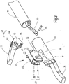
Figur 1 ein erfindungsgemäßes Zangeninstrument, in schematisierter perspektivischer Übersichtsdarstellung, -
Figur 2 das distale Ende des erfindungsgemäßen Zangeninstruments, in perspektivischer Prinzipdarstellung, -
Figur 3 Einzelteile des Zangeninstruments nachFigur 2 , in perspektivischer Darstellung, -
Figur 4 das Zangeninstrument nachFigur 2 , in perspektivischer Ansicht seiner Unterseite, -
Figur 5 eine abgewandelte Ausführungsform des erfindungsgemäßen Zangeninstruments, in perspektivischer Explosionsdarstellung, -
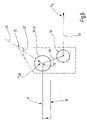
Figur 6 eine skizzenhafte Darstellung der an dem Zangeninstrument angreifenden Kräfte, -
Figur 7 eine Querschnittsdarstellung des Zangeninstruments, geschnitten im Bereich seiner Lagereinrichtung, vereinfacht, -
Figur 8 eine weiter abgewandelte Ausführungsform des erfindungsgemäßen Zangeninstruments, in perspektivischer Explosionsdarstellung -
Figur 9 ein Lagereinsatz für eine erfindungsgemäßes Zangeninstrument in Einbauposition, in perspektivischer Darstellung, -
Figur 10 einen Lagereinsatz für eine erfindungsgemäßes Zangeninstrument, nach Herstellung in perspektivischer Darstellung mit Blick auf seine Außenseite, -
Figur 11 den Lagereinsatz nachFigur 10 , in perspektivischer Darstellung mit Blick auf seine Innenseite. InFigur 1 ist ein Zangeninstrument 10 veranschaulicht, das hier beispielhaft als laparoskopisches Instrument mit einem Schaft 11 dargestellt ist, der endseitig eine Kauterisierungszange 12 trägt. Der Schaft 11 ist an seinem proximalen Ende von einem Gehäuse 13 getragen, das einen Griff 14 und ein Betätigungselement 15 aufweist. Letzteres dient zur Betätigung der Kauterisierungszange 12. Die Kauterisierungszange 12 weist zwei Branchen, nämlich eine erste Branche 16 und eine zweite Branche 17 auf, von denen mindestens ein beweglich gelagert ist und die im vorliegenden Ausführungsbeispiel mit HF-Strom beaufschlagbar sind, um zwischen ihnen gefasstes Gewebe zu koagulieren. Dazu ist das Zangeninstrument 10 über ein Kabel 18 mit einem nicht weiter veranschaulichten Generator verbunden. - Es wird darauf hingewiesen, dass anstelle des Zangeninstruments 10 im Rahmen der Erfindung auch andere Zangeninstrumente in Betracht zu ziehen sind, die zwei Branchen 16 und 17 aufweisen, von denen wenigstens eine gegen die andere beweglich gelagert ist. Das Anwendungsspektrum umfasst sowohl Instrumente für offenchirurgische Anwendungen mit oder ohne Schaft, laparoskopische Instrumente sowie Instrumente für den endoskopischen Einsatz. Zum Anwendungsspektrum gehören sowohl Instrumente mit elektrisch beaufschlagbaren Branchen 16, 17 sowie auch Instrumente mit Branchen, die lediglich eine mechanische Funktion zum Klemmen oder Schneiden haben und die nicht mit strombeaufschlagbar sind. Weiter gehören zum Anwendungsspektrum Instrumente mit einer Schneidvorrichtung, zum Beispiel einem Messer, das in oder an den Branchen 16, 17 zu bewegen ist, wie auch Instrumente ohne ein Messer. Zum Anwendungsspektrum der Erfindung gehören auch Zangeninstrumente mit feststehenden Messern, beispielsweise elektrisch beaufschlagbaren Schneidelektroden.
- Die Kauterisierungszange 12 ist vergrößert in Figur 2 veranschaulicht. Die erste Branche 16 weist eine der zweiten Branche 17 zugewandte Gewebekontaktfläche 19 auf, die beispielsweise eben ausgebildet sein kann. Vorzugsweise ist die Gewebekontaktfläche 19 elektrisch leitend ausgebildet, um über das Kabel 18 mit elektrischer Spannung und Strom versorgt zu werden. Die Branche 16 kann gerade oder, wie dargestellt, leicht seitlich gekrümmt ausgebildet sein. Optional kann in der Gewebekontaktfläche 19 etwa mittig ein Längsschlitz 20 ausgebildet sein, wie er in
Figur 2 gestrichelt veranschaulicht ist. Dieser kann der Führung eines nicht weiter veranschaulichten, axial beweglichen Schneidmessers dienen. Ebenso ist die zweite Branche 17 an ihrer der ersten Branche 16 zugewandten Seite mit einer Gewebekontaktfläche 21 versehen, die vorzugsweise eben ausgebildet ist. Die beiden Branchen 16, 17 sind vorzugsweise konturgleich, so dass sie mit beiden Gewebekontaktflächen 19, 21 passend aufeinander finden, wenn die zweite Branche 17 auf die erste Branche 16 geklappt wird. Auch die zweite Branche 17 kann mit einem Schlitz zur Messerführung versehen sein. Die Gewebekontaktfläche 21 ist vorzugsweise elektrisch leitfähig ausgebildet und beispielsweise über das Kabel 18 mit dem Generator verbindbar. - Wie
Figur 2 weiter erkennen lässt, sind beide Branchen 16, 17 an einem Sockel 22 gehalten, der an dem distalen Ende des Schafts 11 angeordnet ist. Die erste Branche 16 ist dabei vorzugsweise fest mit dem Sockel 22 verbunden. Sie kann beispielsweise durch einen Fortsatz des Sockels 22 gebildet sein, so dass die erste Branche 16 und der Sockel 22 ein einstückiges Teil, zum Beispiel aus Kunststoff oder Keramik oder auch Metall bilden. - Die zweite Branche 17 ist um eine Schwenkachse 23 schwenkbar an dem Sockel 22 gelagert, die quer zu der Längsrichtung des Schafts 11 orientiert ist. Vorzugsweise liegt die Schwenkachse etwa auf der Mitte, d.h. auf dem Durchmesser des Sockelquerschnitts.
- Zur schwenkbaren Lagerung der zweiten Branche 17 dient, wie insbesondere
Figur 3 erkennen lässt, ein Lagereinsatz 24, der ein- oder zweiteilig ausgebildet sein kann und z.B. zwei zueinander spiegelsymmetrisch aufgebaute (oder auch unterschiedlich gestaltete) Lagerteile 25, 26 umfasst. Diese können als separate Teile bereitgestellt werden oder durch einen inFigur 3 verdeckten, zum Beispiel am rechten unteren Ende angeordneten Steg miteinander verbunden sein. Die Verbindung ist dabei so gestaltet, dass die beiden Lagerteile 25, 26 etwas aufeinander zu und voneinander weg federn können. - Der Lagereinsatz 24 ist vorzugsweise ein Kunststoffspritzgussteil, zu dem die beiden Lagerteile 25, 26 gehören und das von den Branchen 16, 17 gesondert ausgebildet und bereitgestellt wird. Es ist jedoch auch möglich, den Lagereinsatz an einer der Branchen 16, 17 mittels Spritzguss direkt anzubringen. Beide Lagerteile 25, 26 bestehen jeweils vorzugsweise aus einem plattenförmigen Grundabschnitt, an dem weitere Strukturen ausgebildet sind, insbesondere ist auf diese Weise eine Lagerstruktur 27 ausgebildet, zu der zwei Lagerelemente 28, 29 gehören. Das Lagerelement 28 wird vorzugsweise durch einen Zylinderzapfen 30 gebildet, der sich von einer Flachseite des Lagerteils 25 zu dem anderen Lagerteil 26 hin erstreckt. Ebenso wird das Lagerelement 29 vorzugsweise durch einen Zapfen 31 gebildet, der sich von dem Lagerteil 26 zu dem Lagerteil 25 hin erstreckt. Die beiden Zapfen 30, 31 sind vorzugsweise Zylinderzapfen, die zwischen einander einen Abstand A einschließen, der insbesondere auch aus
Figur 7 ersichtlich ist. Allerdings ist es auch möglich, die Länge der Zapfen 30, 31 so zu gestalten, dass sie sich mit ihren Stirnseiten oder mit an den Stirnseiten angebrachten Vorsprüngen berühren. Die Durchmesser der Zapfen liegen vorzugsweise im Bereich zwischen 1 mm und 3 mm. Dieser relativ große Durchmesser gestattet die Ausbildung des Lagereinsatzes 24 aus Kunststoff. Gleichzeitig wird eine besonders schlanke Gestaltung des Zangenwerkzeugs ermöglicht, bei dem der Gelenkbereich einen relativ geringen Durchmesser von z.B. lediglich 5 mm - 5,7 mm aufweist. - Die Lagerteile 25, 26 sind an ihren voneinander weg weisenden Seiten mit Führungselementen 33, 34 in Gestalt von Vorsprüngen 35, 36 versehen, die zu einer Verbindungsstruktur 32 gehören. Diese Vorsprünge 35, 36 sind vorzugsweise parallelflankig begrenzte, in Draufsicht rechteckige oder trapezförmige prismatische Vorsprünge, die in einer Richtung quer zu der Schwenkachse 23 in entsprechende an dem Sockel 22 ausgebildete Nuten 37, 38 passen. Die Nuten 37, 38 sind an den aufeinander zu weisenden Wänden eines Fachs 39 ausgebildet (
Figur 3 in Verbindung mitFigur 7 ), in das der Lagereinsatz 24 quer zu der Schwenkachse 23 einschiebbar ist. Dazu weist das Fach 39 ein oberes Fenster 40, aus dem sich die zweite Branche 17 heraus erstreckt, und ein unteres Fenster 41 auf, durch das der Lagereinsatz 24 in das Fach 39 einsetzbar ist. Das Fach 29 ist somit eine in Draufsicht ungefähr rechteckige Durchgangsöffnung durch den Sockel 22. Die zueinander parallelen Flanken der beiden Vorsprünge 35, 36 sind quer zu der Schwenkachse 23 orientiert und legen somit in Verbindung mit den Nuten 37, 38 eine Führungsrichtung F fest, die quer zu der Schwenkachse 23 und zugleich quer zur Längsachse des Schafts 11 steht. Diese Führungsrichtung F ist inFigur 3 und7 jeweils lediglich zur Verdeutlichung durch einen Pfeil markiert. Andere Führungsrichtungen sind möglich. - Die zweite Branche 17 weist an ihrem proximalen Ende einen Scharnierabschnitt 42 auf, der zwei zueinander parallele Wandabschnitte 43, 44 umfassen kann, die beiden zueinander parallelen Wandabschnitte 43, 44 sind jeweils mit einer Öffnung 45, 46 versehen, wobei die Öffnungen 45, 46 vorzugsweise koaxial zueinander angeordnet sein können. Der Durchmesser der beiden Öffnungen 45, 46 kann dabei geringfügig größer sein als der Durchmesser der beiden vorzugsweise zylindrischen Zapfen 30, 31. Dabei ist die Anordnung der Zapfen 30, 31 und der Öffnungen 45, 46 vorzugsweise so getroffen, dass der Mittelpunkt M des Querschnitts des Sockels 21 innerhalb eines von den Öffnungen 45, 46 festgelegten Zylinders liegt. Bei dem Beispiel in
Figur 7 liegt der Mittelpunkt M etwa auf der Schwenkachse 23, was jedoch insoweit nicht zwingend ist. Auch bei einem Versatz des Mittelpunkts M gegen die Schwenkachse 23 innerhalb der oben genannten Bedingung (Mittelpunkt M liegt innerhalb des von den Öffnungen 45, 46 definierten Zylinders) lässt sich eine schlanke und robuste leicht zu montierende Bauform für die Schwenklagerung der Branche 17 erreichen. - Die Verbindungsstruktur 32 kann als Rasteinrichtung ausgebildet sein, indem an den Vorsprüngen 35, 36 weitere Vorsprünge, beispielsweise Rastvorsprünge ausgebildet sind, die in Vertiefungen der Nuten 37, 38 greifen. Alternativ können als Rasteinrichtung 47 Rastvorsprünge 48, 49 an anderen Stellen der Lagerteile 25, 26 angeordnet sein, wie es
Figur 3 prinzipiell veranschaulicht. Alternativ können den Rastvorsprüngen 48, 49, wie esFigur 5 veranschaulicht, entsprechende Rastausnehmungen 50, 51 zugeordnet sein, die zum Beispiel am oberen Rand des Fachs 39 ausgebildet sind. Zur Montage wird die Branche 17 zunächst so zwischen den Lagerteilen 25, 26 angeordnet, dass deren Zapfen 30, 31 in die Öffnungen 45, 46 fassen. Danach werden die Lagerteile 25, 26 federnd zusammengedrückt und diese Anordnung wird von unten her in Richtung F in das Fach 39 eingeführt, bis die Rastvorsprünge 48, 49 in die Ausnehmungen 50, 51 einrasten. Dabei fahren die Vorsprünge 35, 36 in den Nuten 37, 38 in Führungsrichtung F ein, bis sie mit ihren jeweiligen oberen Ecken in entsprechende vorzugsweise spitzwinklige Ecken der zugeordneten Nuten 37, 38 treffen.Figur 6 veranschaulicht dazu eine solche obere Ecke 52 am gestrichelt dargestellten Umriss einer Nut 37, 38. Die gesrichelte Linie 52' veranschaulicht dabei die zumindest vorzugsweise gerundete obere Seite oder Fläche des Vorsprungs 35 und/oder 36. - Der Branche 17 ist eine Betätigungsstange 53 zugeordnet, wie sie aus den
Figuren 3 und5 ersichtlich ist, Diese Betätigungsspanne ist beispielsweise über einen Querzapfen 54 an die Branche 17 angeschlossen, die dazu eine entsprechende Kupplungsöffnung 55 aufweist. - Wie
Figur 4 erkennen lässt, kann der Stift 54 mit seinen beiden Enden jeweils die Außenfläche der Branche 17 etwas überragen, wie inFigur 4 an dem dem Betrachter zugewandten Ende des Stifts 54 dargestellt ist. Das Lagerteil 26 (wie auch das inFigur 4 verdeckte Lagerteil 25) kann für das Ende des Stifts 54 in beiden Endlagen der Branche 17, d.h. in voll geöffnetem wie in voll geschlossenem Zustand jeweils eine Tasche 56, 57 aufweisen, die das Ende des Stifts 54 aufnimmt und diesen bezüglich seiner Längsrichtung (die parallel zu der Schwenkachse 23 ist) sichert. Damit ist ein versehentlicher Verlust des Stifts 54 in Betrieb nicht möglich, während Montage und Demontage desselben in einer Zwischenstellung der Branche 17 zwischen der ganz geschlossenen und ganz offenen Stellung leicht möglich ist. - Zur Funktion und Kinematik des Zangeninstruments 10 wird auf
Figur 6 verwiesen, in der neben der schon angesprochenen gestrichelt dargestellten Kontur des Führungselements 33 und 34 die gemeinsame Kreiskontur der Zapfen 33, 31 veranschaulicht ist, die konzentrisch zu der Schwenkachse 23 sind. Damit ergibt sich bezüglich des Mittelpunkts des Stifts 54 ein Hebelarm 58, an dem die Betätigungsstange 53 mit einer Betätigungskraft FB ziehend angreifen kann. Die inFigur 6 lediglich schematisch veranschaulichte Branche 17 wird dadurch in Richtung auf die Branche 16 gespannt. Dabei treten an der durch die Zapfen 30, 31 gebildeten Lagereinrichtung Lagerreaktionskräfte auf FLR auf, deren Richtung inFigur 6 durch einen Pfeil und eine in Richtung des Pfeils liegende strichpunktierte Linie 59 angedeutet ist. Diese Lagerreaktionskraft FLR zeigt vorzugsweise wenigstens ungefähr in Richtung der Ecke 52, so dass die strichpunktierte Line 59 durch diese Ecke geht. Damit kann insgesamt ein Festsetzen des Lagereinsatzes 24 und eine Entlastung der Rasteinrichtung 47 erreicht werden so dass auch bei großer Kraftbeaufschlagung der Branchen 16, 17 sichergestellt ist, dass der Lagereinsatz 24 ordnungsgemäß in seiner Montageposition bleibt. - In
Figur 8 ist eine weitere Ausführungsform des Zangeninstruments 10 veranschaulicht, zu dessen Aufbau und Funktion zunächst auf die vorstehende Beschreibung, dabei insbesondere die Beschreibung der Ausführungsform nach Figur 5 verwiesen wird. Bei dem Zangeninstrument 10 nach Figur 8 ist zwischen dem Lagereinsatz 24 und der Branche 17 eine Drehwinkelbegrenzungseinrichtung 60 wirksam, die hier beispielhaft durch eine in wenigstens einem der Zapfen 30, 31 vorgesehene Ausnehmung gebildet ist. Dieser Ausnehmung ist ein an dem Rand der Öffnung 45, 46 vorgesehener Vorsprung 61 zugeordnet, der in Umfangrichtung des Zapfens 30, 31 in der Ausnehmung begrenz beweglich ist. Dadurch wird der maximale Schwenkwinkel der Branche 17 begrenzt. - In
Figur 9 ist eine abgewandelte Ausführungsform eines Lagereinsatzes 24 veranschaulicht, der beispielsweise als Spritzgussteil ausgebildet sein kann. Elemente dieses Lagereinsatzes 24, die mit vorbeschriebenen Lagereinsätzen funktions- und/oder strukturgleiche sind, sind inFigur 9 mit bereits eingeführten Bezugszeichen bezeichnet. Die Beschreibung der Ausführungsformen nachFigur 1 bis 8 gilt für den Lagereinsatz 24 nachFigur 9 entsprechend. Der Lagereinsatz 24 ist in Einbauposition dargestellt, in der die Lagerteile 25, 26 nebeneinander in voneinander beabstandeten Ebenen angeordnet sind. Ein die beiden Lagerteile 25, 26 einstückig miteinander verbindender Steg 62 ist unter elastischer und/oder plastischer Verformung u-förmig gebogen. -
Figur 10 und 11 veranschaulichen den Lagereinsatz 24 in gestreckter Position nach der Herstellung, z.B. direkt nach dem Ausformen aus einer Spritzgussform. Der Lagereinsatz ist in dieser Form gut handhabbar und aufbewahrbar. Vor dem Einbau in ein Zangeninstrument, wird er in die Form nachFigur 9 überführt. Als Drehwinkelbegrenzungseinrichtung 60, 60' kann der Zapfen 30, 31 an seiner Stirnseite eine Nase aufweisen. Außerdem kann der Zapfen 31, 31 hohl ausgebildet sein und/oder weitere Strukturen aufweisen. - Die Vorsprünge 35, 36 können massiv ausgebildet oder an ihrer Außenseite mit einer oder mehreren Ausnehmungen versehen sein. Diese Ausnehmungen können z.B. als Nuten gestaltet sein, um eine Verzahnung mit Strukturen in dem Fach 39 zu erreichen.
- Bei dem erfindungsgemäßen Zangeninstrument 10 ist zur Lagerung mindestens einer schwenkbar gelagerten Branche 17 ein Lagereinsatz 24 vorgesehen, der in einen Sockel 22 eingefügt ist, um die wenigstens eine schwenkbare Branche 17 zu lagern. Der Lagereinsatz 24 wird dazu z.B. quer zur Schwenkachse 23 in ein entsprechendes Fach 39 des Sockels 22 eingefügt und dort in dem Fach 39, beispielsweise durch Rastwirkung, befestigt. Der Lagereinsatz 24 weist zwei Lagerelemente 28, 29, beispielsweise in Gestalt zylindrischer Zapfen 30, 31 auf, die von zueinander parallel orientierten beispielsweise plattenförmigen Lagerteilen 25, 26 des Lagereinsatzes 24 aufeinander zuweisend angeordnet sind, ohne einander zu berühren. Die beiden Zapfen 30, 31 greifen in entsprechende Öffnungen 45, 46 der Branche 17, wobei der zwischen den Stirnseiten der Zapfen 30, 31 verbleibende Abstand A zur Anordnung sonstiger Elemente, wie beispielsweise eines Schneidmessers, genutzt werden kann.
-
- 10
- Zangeninstrument
- 11
- Schaft
- 12
- Kauterisierungszange
- 13
- Gehäuse
- 14
- Griff
- 15
- Betätigungselement
- 16
- erste Branche
- 17
- zweite Branche
- 18
- Kabel
- 19
- Gewebekontaktfläche
- 20
- Längsschlitz
- 21
- Gewebekontaktfläche
- 22
- Sockel
- 23
- Schwenkachse
- 24
- Lagereinsatz
- 25, 26
- Lagerteile
- 27
- Lagerstruktur
- 28, 29
- Lagerelemente
- 30, 31
- Zapfen
- A
- Abstand der Stirnseiten der Zapfen 30, 31
- 32
- Verbindungsstruktur
- 33, 34
- Führungselemente
- 35, 36
- Vorsprünge
- 37, 38
- Nuten
- 39
- Fach zur Aufnahme des Lagereinsatzes
- 40
- oberes Fenster
- 41
- unteres Fenster
- 42
- Scharnierabschnitt
- 43, 44
- Wandabschnitt
- 45, 46
- Öffnung
- M
- Querschnittsmitte des zylindrischen Sockels 22
- 47
- Rasteinrichtung
- 48, 49
- Rastvorsprünge
- 50, 51
- Ausnehmungen
- 52
- Ecke
- 52'
- obere Seite des Vorsprungs 35, 36
- 53
- Betätigungsstange
- 54
- Stift
- 55
- Kupplungsöffnung
- 56, 57
- Taschen zur Sicherung des Stifts 54
- 58
- Hebelarm
- FB
- Betätigungskraft
- FLR
- Lagerreaktionskraft
- 59
- Strichpunktlinie
- 60, 60'
- Drehwinkelbegrenzungseinrichtung
- 61
- Vorsprung
- 62
- Steg
Claims (15)
- Zangeninstrument (10) zum Behandeln von biologischem Gewebe,mit einer ersten Branche (16), die an einem Sockel (22) gehalten ist und sich von diesem weg erstreckt, mit einer zweiten Branche (17), die an dem Sockel (22) um eine Schwenkachse (23) schwenkbeweglich gehalten ist,wobei zur schwenkbaren Lagerung der zweiten Branche (17) eine Lagerstruktur (27) mit zwei Lagerelementen (28, 29) vorgesehen ist, die koaxial zueinander angeordnet sind und gemeinsam einen geteilten Lagerzapfen bilden,dadurch gekennzeichnet, dassdie Lagerstruktur (27) an einem aus einem Kunststoff bestehenden Lagereinsatz (24) ausgebildet ist, der mit dem Sockel (22) verbunden ist.
- Zangeninstrument nach Anspruch 1, dadurch gekennzeichnet, dass der Lagereinsatz (24) und eine Verbindungsstruktur (32) zur ortsfesten Lagerung des Lagereinsatzes (24) in dem Sockel (22) aufweist.
- Zangeninstrument nach Anspruch 1 oder 2, dadurch gekennzeichnet, dass der Lagereinsatz (24) quer zu der Schwenkachse (23) in den Sockel (22) einführbar ist.
- Zangeninstrument nach Anspruch 1, dadurch gekennzeichnet, dass der Sockel (22) ein Aufnahmefach (39) für den Lagereinsatz (24) aufweist, wobei der Sockel (22) ein erstes Fenster (40) für die zweite Branche (17) und ein zweites Fenster (41) zur Einführung des Lagereinsatzes (24) in das Aufnahmefach (39) aufweist.
- Zangeninstrument nach einem der vorstehenden Ansprüche, dadurch gekennzeichnet, dass der Lagereinsatz (24) zwei zueinander spiegelsymmetrisch ausgebildete Lagerteile (25, 26) umfasst, an denen die Lagerstruktur (27) und die Verbindungsstruktur (32) ausgebildet ist.
- Zangeninstrument nach einem der vorstehenden Ansprüche, dadurch gekennzeichnet, dass die zwei zueinander koaxial angeordneten Lagerelemente (28, 29) aufeinander zu weisende Zapfen (30, 31) sind, die zwischen einander einen Abstand (A) festlegen.
- Zangeninstrument nach einem der vorstehenden Ansprüche, dadurch gekennzeichnet, dass die zweite Branche (17) an zwei voneinander weg weisenden Seiten zwei zueinander koaxial angeordnete Öffnungen (45, 46) aufweist, die als Drehlager dienen.
- Zangeninstrument nach einem der vorstehenden Ansprüche, dadurch gekennzeichnet, dass die zwei zueinander koaxial angeordneten Lagerelemente (28, 29) zylindrisch ausgebildet sind.
- Zangeninstrument nach einem der vorstehenden Ansprüche, dadurch gekennzeichnet, dass die zwei zueinander koaxial angeordneten Lagerelemente (28, 29) eine Schwenkwinkelbegrenzungseinrichtung (60, 60') aufweisen.
- Zangeninstrument nach einem der vorstehenden Ansprüche, dadurch gekennzeichnet, dass der Lagereinsatz (24) aus PEEK oder LCP oder auch: PPA, PPS, PAI besteht.
- Zangeninstrument Anspruch 9, dadurch gekennzeichnet, dass die zweite Branche (17) an zwei voneinander weg weisenden Seiten zwei zueinander koaxial angeordnete kreisförmige Öffnungen (45, 46) aufweist, die jeweils einen radial nach innen gerichtete Vorsprung aufweisen, der dazu eingerichtet ist, mit der Drehwinkelbegrenzungseinrichtung (60, 60') zusammenzuwirken.
- Zangeninstrument nach einem der vorstehenden Ansprüche, dadurch gekennzeichnet, dass der Lagereinsatz (24) an voneinander weg weisenden Seiten Führungselemente (33, 34) aufweist, die, zusammen mit einer dazu komplementären, in dem Sockel (22) ausgebildeten Struktur eine Führungsrichtung (F) festlegt, die quer zu der Schwenkachse (23) orientiert ist, wobei die Führungselemente (33, 34) vorzugsweise durch polygonal umgrenzte Vorsprünge gebildet sind.
- Zangeninstrument nach Anspruch 12, dadurch gekennzeichnet, dass jeder Vorsprung eine spitzwinklige Ecke (52) aufweist, die bei geschlossenen Zangeninstrument (10) in einer Kraftrichtung (FLR) weist, um durch ihr Geometrie bei geschlossenen Maulteil in einer Kraftrichtung zu einer Selbstverklemmung zu führen.
- Zangeninstrument nach einem der vorstehenden Ansprüche, dadurch gekennzeichnet, dass zwischen dem Lagereinsatz (24) und dem Sockel (22) wirkend eine Rasteinrichtung vorgesehen ist.
- Verfahren zur Bereitstellung eines Zangeninstruments nach einem der vorstehenden Ansprüche, dadurch gekennzeichnet, dass die Lagerstruktur (27)zunächst in Gestalt eines gestreckten Teils bereitgestellt wird, bei dem beide Lagerteile (25, 26) und ein Verbindungssteg (62) in einer gemeinsamen Ebene angeordnet sind,wonach die Lagerteile (25, 26) unter Verbiegung oder Entfernung oder Unterbrechung des Verbindungsstegs in zwei zueinander parallele, voneinander beabstandete Ebenen überführt werden,wonach die Lagerstruktur (27) in das Fach (39) eingesetzt wird.
Priority Applications (8)
| Application Number | Priority Date | Filing Date | Title |
|---|---|---|---|
| EP18198761.1A EP3632354B1 (de) | 2018-10-05 | 2018-10-05 | Gewebezange |
| PL18198761.1T PL3632354T3 (pl) | 2018-10-05 | 2018-10-05 | Szczypce do tkanki |
| BR102019019970A BR102019019970A2 (pt) | 2018-10-05 | 2019-09-24 | pinças de tecido e método para fornecer |
| RU2019130405A RU2795532C2 (ru) | 2018-10-05 | 2019-09-26 | Хирургический щипцовый инструмент и способ монтажа в нем опорной структуры |
| CN201910923237.XA CN111000618B (zh) | 2018-10-05 | 2019-09-27 | 组织钳子 |
| JP2019183134A JP7372807B2 (ja) | 2018-10-05 | 2019-10-03 | 組織鉗子 |
| US16/592,096 US11497542B2 (en) | 2018-10-05 | 2019-10-03 | Tissue forceps |
| KR1020190122975A KR102817261B1 (ko) | 2018-10-05 | 2019-10-04 | 조직 겸자 |
Applications Claiming Priority (1)
| Application Number | Priority Date | Filing Date | Title |
|---|---|---|---|
| EP18198761.1A EP3632354B1 (de) | 2018-10-05 | 2018-10-05 | Gewebezange |
Publications (2)
| Publication Number | Publication Date |
|---|---|
| EP3632354A1 EP3632354A1 (de) | 2020-04-08 |
| EP3632354B1 true EP3632354B1 (de) | 2022-08-31 |
Family
ID=63787765
Family Applications (1)
| Application Number | Title | Priority Date | Filing Date |
|---|---|---|---|
| EP18198761.1A Active EP3632354B1 (de) | 2018-10-05 | 2018-10-05 | Gewebezange |
Country Status (7)
| Country | Link |
|---|---|
| US (1) | US11497542B2 (de) |
| EP (1) | EP3632354B1 (de) |
| JP (1) | JP7372807B2 (de) |
| KR (1) | KR102817261B1 (de) |
| CN (1) | CN111000618B (de) |
| BR (1) | BR102019019970A2 (de) |
| PL (1) | PL3632354T3 (de) |
Cited By (1)
| Publication number | Priority date | Publication date | Assignee | Title |
|---|---|---|---|---|
| EP4674362A1 (de) | 2024-07-02 | 2026-01-07 | Erbe Elektromedizin GmbH | Werkzeugeinheit für ein koagulations- und dissektionsinstrument |
Families Citing this family (1)
| Publication number | Priority date | Publication date | Assignee | Title |
|---|---|---|---|---|
| EP4580526A1 (de) | 2022-12-08 | 2025-07-09 | 3D Microprint GmbH | Werkzeug zur anwendung als mikromanipulator und verfahren zur herstellung des werkzeuges |
Family Cites Families (34)
| Publication number | Priority date | Publication date | Assignee | Title |
|---|---|---|---|---|
| US4815476A (en) | 1988-03-28 | 1989-03-28 | Cordis Corporation | Biopsy forceps with locking handle |
| US5190541A (en) | 1990-10-17 | 1993-03-02 | Boston Scientific Corporation | Surgical instrument and method |
| CA2106039A1 (en) | 1992-09-23 | 1994-03-24 | David A. Nicholas | Surgical biopsy forceps apparatus |
| DE19515914C1 (de) | 1995-05-02 | 1996-07-25 | Aesculap Ag | Zangen- oder scherenförmiges chirurgisches Instrument |
| CN2273640Y (zh) * | 1996-05-09 | 1998-02-04 | 刘培根 | 一种改良的附钳夹之剪刀 |
| US6113598A (en) | 1998-02-17 | 2000-09-05 | Baker; James A. | Radiofrequency medical instrument and methods for vessel welding |
| US6585735B1 (en) | 1998-10-23 | 2003-07-01 | Sherwood Services Ag | Endoscopic bipolar electrosurgical forceps |
| US6174309B1 (en) | 1999-02-11 | 2001-01-16 | Medical Scientific, Inc. | Seal & cut electrosurgical instrument |
| US6953461B2 (en) | 2002-05-16 | 2005-10-11 | Tissuelink Medical, Inc. | Fluid-assisted medical devices, systems and methods |
| US6656177B2 (en) | 2000-10-23 | 2003-12-02 | Csaba Truckai | Electrosurgical systems and techniques for sealing tissue |
| US20020143358A1 (en) | 2001-02-13 | 2002-10-03 | Domingo Nicanor A. | Method and apparatus for micro-dissection of vascular occlusions |
| US7131977B2 (en) | 2002-08-27 | 2006-11-07 | Pilling Weck Incorporated | Apparatus and method for removing a clip |
| US7931649B2 (en) | 2002-10-04 | 2011-04-26 | Tyco Healthcare Group Lp | Vessel sealing instrument with electrical cutting mechanism |
| US7276068B2 (en) | 2002-10-04 | 2007-10-02 | Sherwood Services Ag | Vessel sealing instrument with electrical cutting mechanism |
| US7632269B2 (en) | 2004-01-16 | 2009-12-15 | Ethicon Endo-Surgery, Inc. | Electrosurgical instrument with replaceable cartridge |
| DE102004013530B4 (de) * | 2004-03-19 | 2011-02-17 | Sutter Medizintechnik Gmbh | Bipolare Koagulationszange |
| US7857183B2 (en) | 2004-07-28 | 2010-12-28 | Ethicon Endo-Surgery, Inc. | Surgical instrument incorporating an electrically actuated articulation mechanism |
| DE102004040959B4 (de) | 2004-08-24 | 2008-12-24 | Erbe Elektromedizin Gmbh | Chirurgisches Instrument |
| DE102006062848B4 (de) | 2006-06-14 | 2013-01-31 | Karl Storz Gmbh & Co. Kg | Chirurgische Greifzange |
| ATE544412T1 (de) | 2006-10-05 | 2012-02-15 | Erbe Elektromedizin | Rohrschaftinstrument |
| DE202007009165U1 (de) * | 2007-06-29 | 2007-08-30 | Kls Martin Gmbh + Co. Kg | Chirurgisches Instrument |
| US8758342B2 (en) | 2007-11-28 | 2014-06-24 | Covidien Ag | Cordless power-assisted medical cauterization and cutting device |
| US9050098B2 (en) | 2007-11-28 | 2015-06-09 | Covidien Ag | Cordless medical cauterization and cutting device |
| GB0804688D0 (en) | 2008-03-13 | 2008-04-16 | Gyrus Group Plc | Surgical instrument |
| DE102009049401B4 (de) | 2009-08-20 | 2023-09-28 | Erbe Elektromedizin Gmbh | Elektrochirurgische Zange |
| US8512371B2 (en) | 2009-10-06 | 2013-08-20 | Covidien Lp | Jaw, blade and gap manufacturing for surgical instruments with small jaws |
| CN101779979B (zh) | 2010-01-08 | 2013-01-02 | 瑞奇外科器械(中国)有限公司 | 全纵向超声外科手术系统 |
| US20110257680A1 (en) | 2010-04-20 | 2011-10-20 | Tyco Healthcare Group Lp | Surgical Forceps Including Pulley Blade Reverser Mechanism |
| JP6518403B2 (ja) * | 2011-02-18 | 2019-05-22 | インテュイティブ サージカル オペレーションズ, インコーポレイテッド | 融合及び切断用外科用器具とこれに関連する方法 |
| US8864795B2 (en) | 2011-10-03 | 2014-10-21 | Covidien Lp | Surgical forceps |
| US9301798B2 (en) * | 2012-07-19 | 2016-04-05 | Covidien Lp | Surgical forceps including reposable end effector assemblies |
| PL2845548T3 (pl) | 2013-09-10 | 2017-04-28 | Erbe Elektromedizin Gmbh | Przyrząd chirurgiczny z odchylnymi szczękami |
| PL2959854T3 (pl) | 2014-06-25 | 2018-07-31 | Erbe Elektromedizin Gmbh | Instrument chirurgiczny |
| US10639035B2 (en) | 2016-12-21 | 2020-05-05 | Ethicon Llc | Surgical stapling instruments and replaceable tool assemblies thereof |
-
2018
- 2018-10-05 EP EP18198761.1A patent/EP3632354B1/de active Active
- 2018-10-05 PL PL18198761.1T patent/PL3632354T3/pl unknown
-
2019
- 2019-09-24 BR BR102019019970A patent/BR102019019970A2/pt unknown
- 2019-09-27 CN CN201910923237.XA patent/CN111000618B/zh active Active
- 2019-10-03 JP JP2019183134A patent/JP7372807B2/ja active Active
- 2019-10-03 US US16/592,096 patent/US11497542B2/en active Active
- 2019-10-04 KR KR1020190122975A patent/KR102817261B1/ko active Active
Cited By (1)
| Publication number | Priority date | Publication date | Assignee | Title |
|---|---|---|---|---|
| EP4674362A1 (de) | 2024-07-02 | 2026-01-07 | Erbe Elektromedizin GmbH | Werkzeugeinheit für ein koagulations- und dissektionsinstrument |
Also Published As
| Publication number | Publication date |
|---|---|
| US20200107873A1 (en) | 2020-04-09 |
| RU2019130405A (ru) | 2021-03-26 |
| JP2020096791A (ja) | 2020-06-25 |
| CN111000618A (zh) | 2020-04-14 |
| JP7372807B2 (ja) | 2023-11-01 |
| KR20200039594A (ko) | 2020-04-16 |
| KR102817261B1 (ko) | 2025-06-09 |
| US11497542B2 (en) | 2022-11-15 |
| PL3632354T3 (pl) | 2022-11-07 |
| BR102019019970A2 (pt) | 2020-04-14 |
| EP3632354A1 (de) | 2020-04-08 |
| CN111000618B (zh) | 2023-09-01 |
Similar Documents
| Publication | Publication Date | Title |
|---|---|---|
| DE102007053359B3 (de) | Chirurgisches Instrument | |
| EP2845548B1 (de) | Chirurgisches Instrument mit schwenkbaren Branchen | |
| EP2755586B1 (de) | Elektrochirurgisches instrument | |
| EP2112909A1 (de) | Chirurgisches instrument | |
| EP1126790A1 (de) | Medizinisches instrument zum schneiden von gewebe im menschlichen oder tierischen körper | |
| WO2011018154A1 (de) | Elektrochirurgisches instrument | |
| EP1107703A1 (de) | Medizinisches bipolares instrument zum schneiden von gewebe | |
| DE102011081464A1 (de) | Werkzeug für ein mikroinvasiv-chirurgisches Instrument | |
| EP2679186B1 (de) | Instrument zur Gefäßfusion und -trennung | |
| DE102011079494A1 (de) | Elektrochirurgisches Greifinstrument | |
| EP1778113A1 (de) | Elektrochirurgisches instrument | |
| EP3632354B1 (de) | Gewebezange | |
| DE202007015547U1 (de) | Chirurgisches Instrument | |
| EP3578118B1 (de) | Chirurgisches instrument | |
| EP2554133A1 (de) | Instrument zur Gefäßfusion und -trennung mit zwei Branchen und einer gekrümmten Elektrode | |
| EP2464302A1 (de) | Elektrochirurgisches instrument | |
| EP3201990B1 (de) | Anschlussklemme | |
| EP1168972B1 (de) | Chirurgisches instrument | |
| EP3583906A1 (de) | Schaft für ein medizinisches instrument sowie medizinisches instrument, insbesondere mono- oder bipolares medizinisches instrument | |
| EP4371514A1 (de) | Medizinisches thermofusionsinstrument | |
| DE102024134411B3 (de) | Chirurgisches Maulteilwerkzeug, chirurgisches Instrument und robotisches chirurgisches Instrumentensystem | |
| EP1871259A1 (de) | Elektrochirurgisches instrument | |
| EP4527330B1 (de) | Schlittenvorrichtung für ein chirurgisches instrument | |
| EP1771120B1 (de) | Adaptervorrichtung | |
| EP1717836B1 (de) | Sicherungshalter, insbesondere für Sicherungssockel und Sicherungslasttrennschalter |
Legal Events
| Date | Code | Title | Description |
|---|---|---|---|
| PUAI | Public reference made under article 153(3) epc to a published international application that has entered the european phase |
Free format text: ORIGINAL CODE: 0009012 |
|
| STAA | Information on the status of an ep patent application or granted ep patent |
Free format text: STATUS: THE APPLICATION HAS BEEN PUBLISHED |
|
| AK | Designated contracting states |
Kind code of ref document: A1 Designated state(s): AL AT BE BG CH CY CZ DE DK EE ES FI FR GB GR HR HU IE IS IT LI LT LU LV MC MK MT NL NO PL PT RO RS SE SI SK SM TR |
|
| AX | Request for extension of the european patent |
Extension state: BA ME |
|
| STAA | Information on the status of an ep patent application or granted ep patent |
Free format text: STATUS: REQUEST FOR EXAMINATION WAS MADE |
|
| 17P | Request for examination filed |
Effective date: 20200903 |
|
| RBV | Designated contracting states (corrected) |
Designated state(s): AL AT BE BG CH CY CZ DE DK EE ES FI FR GB GR HR HU IE IS IT LI LT LU LV MC MK MT NL NO PL PT RO RS SE SI SK SM TR |
|
| GRAP | Despatch of communication of intention to grant a patent |
Free format text: ORIGINAL CODE: EPIDOSNIGR1 |
|
| STAA | Information on the status of an ep patent application or granted ep patent |
Free format text: STATUS: GRANT OF PATENT IS INTENDED |
|
| INTG | Intention to grant announced |
Effective date: 20220331 |
|
| GRAS | Grant fee paid |
Free format text: ORIGINAL CODE: EPIDOSNIGR3 |
|
| GRAA | (expected) grant |
Free format text: ORIGINAL CODE: 0009210 |
|
| STAA | Information on the status of an ep patent application or granted ep patent |
Free format text: STATUS: THE PATENT HAS BEEN GRANTED |
|
| AK | Designated contracting states |
Kind code of ref document: B1 Designated state(s): AL AT BE BG CH CY CZ DE DK EE ES FI FR GB GR HR HU IE IS IT LI LT LU LV MC MK MT NL NO PL PT RO RS SE SI SK SM TR |
|
| REG | Reference to a national code |
Ref country code: CH Ref legal event code: EP Ref country code: GB Ref legal event code: FG4D Free format text: NOT ENGLISH |
|
| REG | Reference to a national code |
Ref country code: AT Ref legal event code: REF Ref document number: 1514724 Country of ref document: AT Kind code of ref document: T Effective date: 20220915 Ref country code: DE Ref legal event code: R096 Ref document number: 502018010519 Country of ref document: DE |
|
| REG | Reference to a national code |
Ref country code: IE Ref legal event code: FG4D Free format text: LANGUAGE OF EP DOCUMENT: GERMAN |
|
| REG | Reference to a national code |
Ref country code: LT Ref legal event code: MG9D |
|
| REG | Reference to a national code |
Ref country code: NL Ref legal event code: MP Effective date: 20220831 |
|
| PG25 | Lapsed in a contracting state [announced via postgrant information from national office to epo] |
Ref country code: SE Free format text: LAPSE BECAUSE OF FAILURE TO SUBMIT A TRANSLATION OF THE DESCRIPTION OR TO PAY THE FEE WITHIN THE PRESCRIBED TIME-LIMIT Effective date: 20220831 Ref country code: RS Free format text: LAPSE BECAUSE OF FAILURE TO SUBMIT A TRANSLATION OF THE DESCRIPTION OR TO PAY THE FEE WITHIN THE PRESCRIBED TIME-LIMIT Effective date: 20220831 Ref country code: NO Free format text: LAPSE BECAUSE OF FAILURE TO SUBMIT A TRANSLATION OF THE DESCRIPTION OR TO PAY THE FEE WITHIN THE PRESCRIBED TIME-LIMIT Effective date: 20221130 Ref country code: LV Free format text: LAPSE BECAUSE OF FAILURE TO SUBMIT A TRANSLATION OF THE DESCRIPTION OR TO PAY THE FEE WITHIN THE PRESCRIBED TIME-LIMIT Effective date: 20220831 Ref country code: LT Free format text: LAPSE BECAUSE OF FAILURE TO SUBMIT A TRANSLATION OF THE DESCRIPTION OR TO PAY THE FEE WITHIN THE PRESCRIBED TIME-LIMIT Effective date: 20220831 Ref country code: FI Free format text: LAPSE BECAUSE OF FAILURE TO SUBMIT A TRANSLATION OF THE DESCRIPTION OR TO PAY THE FEE WITHIN THE PRESCRIBED TIME-LIMIT Effective date: 20220831 |
|
| PG25 | Lapsed in a contracting state [announced via postgrant information from national office to epo] |
Ref country code: IS Free format text: LAPSE BECAUSE OF FAILURE TO SUBMIT A TRANSLATION OF THE DESCRIPTION OR TO PAY THE FEE WITHIN THE PRESCRIBED TIME-LIMIT Effective date: 20221231 Ref country code: HR Free format text: LAPSE BECAUSE OF FAILURE TO SUBMIT A TRANSLATION OF THE DESCRIPTION OR TO PAY THE FEE WITHIN THE PRESCRIBED TIME-LIMIT Effective date: 20220831 Ref country code: GR Free format text: LAPSE BECAUSE OF FAILURE TO SUBMIT A TRANSLATION OF THE DESCRIPTION OR TO PAY THE FEE WITHIN THE PRESCRIBED TIME-LIMIT Effective date: 20221201 |
|
| PG25 | Lapsed in a contracting state [announced via postgrant information from national office to epo] |
Ref country code: SM Free format text: LAPSE BECAUSE OF FAILURE TO SUBMIT A TRANSLATION OF THE DESCRIPTION OR TO PAY THE FEE WITHIN THE PRESCRIBED TIME-LIMIT Effective date: 20220831 Ref country code: RO Free format text: LAPSE BECAUSE OF FAILURE TO SUBMIT A TRANSLATION OF THE DESCRIPTION OR TO PAY THE FEE WITHIN THE PRESCRIBED TIME-LIMIT Effective date: 20220831 Ref country code: PT Free format text: LAPSE BECAUSE OF FAILURE TO SUBMIT A TRANSLATION OF THE DESCRIPTION OR TO PAY THE FEE WITHIN THE PRESCRIBED TIME-LIMIT Effective date: 20230102 Ref country code: ES Free format text: LAPSE BECAUSE OF FAILURE TO SUBMIT A TRANSLATION OF THE DESCRIPTION OR TO PAY THE FEE WITHIN THE PRESCRIBED TIME-LIMIT Effective date: 20220831 Ref country code: DK Free format text: LAPSE BECAUSE OF FAILURE TO SUBMIT A TRANSLATION OF THE DESCRIPTION OR TO PAY THE FEE WITHIN THE PRESCRIBED TIME-LIMIT Effective date: 20220831 Ref country code: CZ Free format text: LAPSE BECAUSE OF FAILURE TO SUBMIT A TRANSLATION OF THE DESCRIPTION OR TO PAY THE FEE WITHIN THE PRESCRIBED TIME-LIMIT Effective date: 20220831 |
|
| PG25 | Lapsed in a contracting state [announced via postgrant information from national office to epo] |
Ref country code: SK Free format text: LAPSE BECAUSE OF FAILURE TO SUBMIT A TRANSLATION OF THE DESCRIPTION OR TO PAY THE FEE WITHIN THE PRESCRIBED TIME-LIMIT Effective date: 20220831 Ref country code: MC Free format text: LAPSE BECAUSE OF FAILURE TO SUBMIT A TRANSLATION OF THE DESCRIPTION OR TO PAY THE FEE WITHIN THE PRESCRIBED TIME-LIMIT Effective date: 20220831 Ref country code: EE Free format text: LAPSE BECAUSE OF FAILURE TO SUBMIT A TRANSLATION OF THE DESCRIPTION OR TO PAY THE FEE WITHIN THE PRESCRIBED TIME-LIMIT Effective date: 20220831 |
|
| REG | Reference to a national code |
Ref country code: CH Ref legal event code: PL |
|
| REG | Reference to a national code |
Ref country code: DE Ref legal event code: R097 Ref document number: 502018010519 Country of ref document: DE |
|
| REG | Reference to a national code |
Ref country code: BE Ref legal event code: MM Effective date: 20221031 |
|
| PG25 | Lapsed in a contracting state [announced via postgrant information from national office to epo] |
Ref country code: NL Free format text: LAPSE BECAUSE OF FAILURE TO SUBMIT A TRANSLATION OF THE DESCRIPTION OR TO PAY THE FEE WITHIN THE PRESCRIBED TIME-LIMIT Effective date: 20220831 Ref country code: LU Free format text: LAPSE BECAUSE OF NON-PAYMENT OF DUE FEES Effective date: 20221005 Ref country code: AL Free format text: LAPSE BECAUSE OF FAILURE TO SUBMIT A TRANSLATION OF THE DESCRIPTION OR TO PAY THE FEE WITHIN THE PRESCRIBED TIME-LIMIT Effective date: 20220831 |
|
| PLBE | No opposition filed within time limit |
Free format text: ORIGINAL CODE: 0009261 |
|
| STAA | Information on the status of an ep patent application or granted ep patent |
Free format text: STATUS: NO OPPOSITION FILED WITHIN TIME LIMIT |
|
| PG25 | Lapsed in a contracting state [announced via postgrant information from national office to epo] |
Ref country code: LI Free format text: LAPSE BECAUSE OF NON-PAYMENT OF DUE FEES Effective date: 20221031 Ref country code: CH Free format text: LAPSE BECAUSE OF NON-PAYMENT OF DUE FEES Effective date: 20221031 |
|
| 26N | No opposition filed |
Effective date: 20230601 |
|
| PG25 | Lapsed in a contracting state [announced via postgrant information from national office to epo] |
Ref country code: SI Free format text: LAPSE BECAUSE OF FAILURE TO SUBMIT A TRANSLATION OF THE DESCRIPTION OR TO PAY THE FEE WITHIN THE PRESCRIBED TIME-LIMIT Effective date: 20220831 |
|
| PG25 | Lapsed in a contracting state [announced via postgrant information from national office to epo] |
Ref country code: BE Free format text: LAPSE BECAUSE OF NON-PAYMENT OF DUE FEES Effective date: 20221031 |
|
| PG25 | Lapsed in a contracting state [announced via postgrant information from national office to epo] |
Ref country code: IE Free format text: LAPSE BECAUSE OF NON-PAYMENT OF DUE FEES Effective date: 20221005 |
|
| PG25 | Lapsed in a contracting state [announced via postgrant information from national office to epo] |
Ref country code: HU Free format text: LAPSE BECAUSE OF FAILURE TO SUBMIT A TRANSLATION OF THE DESCRIPTION OR TO PAY THE FEE WITHIN THE PRESCRIBED TIME-LIMIT; INVALID AB INITIO Effective date: 20181005 |
|
| PG25 | Lapsed in a contracting state [announced via postgrant information from national office to epo] |
Ref country code: CY Free format text: LAPSE BECAUSE OF FAILURE TO SUBMIT A TRANSLATION OF THE DESCRIPTION OR TO PAY THE FEE WITHIN THE PRESCRIBED TIME-LIMIT Effective date: 20220831 |
|
| PG25 | Lapsed in a contracting state [announced via postgrant information from national office to epo] |
Ref country code: MK Free format text: LAPSE BECAUSE OF FAILURE TO SUBMIT A TRANSLATION OF THE DESCRIPTION OR TO PAY THE FEE WITHIN THE PRESCRIBED TIME-LIMIT Effective date: 20220831 |
|
| PG25 | Lapsed in a contracting state [announced via postgrant information from national office to epo] |
Ref country code: TR Free format text: LAPSE BECAUSE OF FAILURE TO SUBMIT A TRANSLATION OF THE DESCRIPTION OR TO PAY THE FEE WITHIN THE PRESCRIBED TIME-LIMIT Effective date: 20220831 |
|
| PG25 | Lapsed in a contracting state [announced via postgrant information from national office to epo] |
Ref country code: BG Free format text: LAPSE BECAUSE OF FAILURE TO SUBMIT A TRANSLATION OF THE DESCRIPTION OR TO PAY THE FEE WITHIN THE PRESCRIBED TIME-LIMIT Effective date: 20220831 |
|
| PG25 | Lapsed in a contracting state [announced via postgrant information from national office to epo] |
Ref country code: MT Free format text: LAPSE BECAUSE OF FAILURE TO SUBMIT A TRANSLATION OF THE DESCRIPTION OR TO PAY THE FEE WITHIN THE PRESCRIBED TIME-LIMIT Effective date: 20220831 |
|
| REG | Reference to a national code |
Ref country code: AT Ref legal event code: MM01 Ref document number: 1514724 Country of ref document: AT Kind code of ref document: T Effective date: 20231005 |
|
| PG25 | Lapsed in a contracting state [announced via postgrant information from national office to epo] |
Ref country code: AT Free format text: LAPSE BECAUSE OF NON-PAYMENT OF DUE FEES Effective date: 20231005 |
|
| PG25 | Lapsed in a contracting state [announced via postgrant information from national office to epo] |
Ref country code: AT Free format text: LAPSE BECAUSE OF NON-PAYMENT OF DUE FEES Effective date: 20231005 |
|
| PGFP | Annual fee paid to national office [announced via postgrant information from national office to epo] |
Ref country code: PL Payment date: 20250910 Year of fee payment: 8 |
|
| PGFP | Annual fee paid to national office [announced via postgrant information from national office to epo] |
Ref country code: DE Payment date: 20251028 Year of fee payment: 8 |
|
| PGFP | Annual fee paid to national office [announced via postgrant information from national office to epo] |
Ref country code: GB Payment date: 20251023 Year of fee payment: 8 |
|
| PGFP | Annual fee paid to national office [announced via postgrant information from national office to epo] |
Ref country code: IT Payment date: 20251022 Year of fee payment: 8 |
|
| PGFP | Annual fee paid to national office [announced via postgrant information from national office to epo] |
Ref country code: FR Payment date: 20251027 Year of fee payment: 8 |
|
| PGFP | Annual fee paid to national office [announced via postgrant information from national office to epo] |
Ref country code: AT Payment date: 20260410 Year of fee payment: 5 |