EP3632194B1 - Explosionssicheres gehäuse mit innerer druckreduzierung - Google Patents
Explosionssicheres gehäuse mit innerer druckreduzierung Download PDFInfo
- Publication number
- EP3632194B1 EP3632194B1 EP18713624.7A EP18713624A EP3632194B1 EP 3632194 B1 EP3632194 B1 EP 3632194B1 EP 18713624 A EP18713624 A EP 18713624A EP 3632194 B1 EP3632194 B1 EP 3632194B1
- Authority
- EP
- European Patent Office
- Prior art keywords
- open
- housing
- walls
- housing according
- wall
- Prior art date
- Legal status (The legal status is an assumption and is not a legal conclusion. Google has not performed a legal analysis and makes no representation as to the accuracy of the status listed.)
- Active
Links
Images

Classifications
-
- H—ELECTRICITY
- H05—ELECTRIC TECHNIQUES NOT OTHERWISE PROVIDED FOR
- H05K—PRINTED CIRCUITS; CASINGS OR CONSTRUCTIONAL DETAILS OF ELECTRIC APPARATUS; MANUFACTURE OF ASSEMBLAGES OF ELECTRICAL COMPONENTS
- H05K5/00—Casings, cabinets or drawers for electric apparatus
- H05K5/02—Details
- H05K5/0213—Venting apertures; Constructional details thereof
-
- H—ELECTRICITY
- H01—ELECTRIC ELEMENTS
- H01H—ELECTRIC SWITCHES; RELAYS; SELECTORS; EMERGENCY PROTECTIVE DEVICES
- H01H9/00—Details of switching devices, not covered by groups H01H1/00 - H01H7/00
- H01H9/02—Bases, casings, or covers
- H01H9/04—Dustproof, splashproof, drip-proof, waterproof, or flameproof casings
- H01H9/042—Explosion-proof cases
-
- H—ELECTRICITY
- H02—GENERATION; CONVERSION OR DISTRIBUTION OF ELECTRIC POWER
- H02B—BOARDS, SUBSTATIONS OR SWITCHING ARRANGEMENTS FOR THE SUPPLY OR DISTRIBUTION OF ELECTRIC POWER
- H02B1/00—Frameworks, boards, panels, desks, casings; Details of substations or switching arrangements
- H02B1/26—Casings; Parts thereof or accessories therefor
- H02B1/28—Casings; Parts thereof or accessories therefor dustproof, splashproof, drip-proof, waterproof or flameproof
-
- H—ELECTRICITY
- H02—GENERATION; CONVERSION OR DISTRIBUTION OF ELECTRIC POWER
- H02B—BOARDS, SUBSTATIONS OR SWITCHING ARRANGEMENTS FOR THE SUPPLY OR DISTRIBUTION OF ELECTRIC POWER
- H02B13/00—Arrangement of switchgear in which switches are enclosed in, or structurally associated with, a casing, e.g. cubicle
- H02B13/02—Arrangement of switchgear in which switches are enclosed in, or structurally associated with, a casing, e.g. cubicle with metal casing
- H02B13/025—Safety arrangements, e.g. in case of excessive pressure or fire due to electrical defect
-
- H—ELECTRICITY
- H02—GENERATION; CONVERSION OR DISTRIBUTION OF ELECTRIC POWER
- H02K—DYNAMO-ELECTRIC MACHINES
- H02K5/00—Casings; Enclosures; Supports
- H02K5/04—Casings or enclosures characterised by the shape, form or construction thereof
- H02K5/12—Casings or enclosures characterised by the shape, form or construction thereof specially adapted for operating in liquid or gas
- H02K5/136—Casings or enclosures characterised by the shape, form or construction thereof specially adapted for operating in liquid or gas explosion-proof
-
- H—ELECTRICITY
- H05—ELECTRIC TECHNIQUES NOT OTHERWISE PROVIDED FOR
- H05K—PRINTED CIRCUITS; CASINGS OR CONSTRUCTIONAL DETAILS OF ELECTRIC APPARATUS; MANUFACTURE OF ASSEMBLAGES OF ELECTRICAL COMPONENTS
- H05K5/00—Casings, cabinets or drawers for electric apparatus
- H05K5/02—Details
- H05K5/0217—Mechanical details of casings
-
- H—ELECTRICITY
- H05—ELECTRIC TECHNIQUES NOT OTHERWISE PROVIDED FOR
- H05K—PRINTED CIRCUITS; CASINGS OR CONSTRUCTIONAL DETAILS OF ELECTRIC APPARATUS; MANUFACTURE OF ASSEMBLAGES OF ELECTRICAL COMPONENTS
- H05K5/00—Casings, cabinets or drawers for electric apparatus
- H05K5/02—Details
- H05K5/0209—Thermal insulation, e.g. for fire protection or for fire containment or for high temperature environments
Definitions
- the subject of the invention is an explosion-proof housing, in particular a single- or multi-chamber housing with protection class Ex-d.
- Housings with protection class Ex-d are often used in potentially explosive areas. Such housings are designed to be so resistant that they can withstand the ignition of an explosive gas mixture in their interior and the subsequent increase in pressure as a result of the explosion occurring. In addition, the housings are designed in such a way that no flames or glowing particles that act as ignition sources can escape to the outside. If there are gaps, they must have a minimum length and must not exceed a maximum width.
- Existing housing openings are provided with pressure relief bodies, which are also referred to as flame protection filters and prevent a flame ignited in the housing from penetrating to the outside and igniting any explosive mixture present in the environment, while on the other hand they equalize the pressure with the environment.
- the DD 261 063 A3 describes an explosion-proof housing with a porous body arranged in its interior, for example made of slag wool, glass wool, metal or ceramic with open, continuous pores or gaps. Such a body arranged in the housing should lead to a reduction in the explosion pressure by approximately 90%.
- the DE 198 60 286 B4 discloses a housing intended for a screen, the interior of which is partially filled with a porous damping material to reduce the explosion pressure.
- the material has a large number of small cross-sectional, not closed, but continuous channels in the form of pores or gaps. The aim is to reduce the explosion pressure to only around 10 percent of the explosion pressure that would otherwise occur in the empty housing.
- Some of the known housings with bodies made of open-pored material are special solutions that are relatively spacious and/or are very well adapted to the specific circumstances, such as tablet computers.
- the DE 10 2013 109 259 A1 describes an explosion-proof housing with the protection class flameproof enclosure (Ex-d), in the housing wall of which a porous pressure relief body is provided, through which an explosion pressure built up in the housing can penetrate to the outside.
- the housings also use this principle US 4,180,177 as well as after the DE 10 2010 016 782 B4.
- a housing is known with which electrical devices can be operated safely in potentially explosive environments.
- the housing is intended to ensure that there are no hazards such as sparks in the event of an explosion within the housing Skip the potentially explosive atmosphere.
- energy-absorbing material are metallic honeycomb structures, porous organic fillers, such as corn cobs or organic fibers, such as flax fibers bonded with epoxy resin. This material is used to cover any openings and flame paths, which is intended to fulfill a dual function, namely cooling the escaping hot gas and dampening the pressure and shock waves.
- the arrangement of pressure wave-absorbing material in an otherwise closed housing is also from the DE 20 2015 005 015 U1 known.
- the housing presented there is closed to the outside. Inside it has one or two shock wave-absorbing elements, which are arranged, for example, on walls that are at an angle to one another or freely traversing the room.
- Such pressure relief bodies are subject to contamination when such housings are arranged in an adverse environment or to germination, icing and/or corrosion when exposed to weather. Taking such circumstances into account leads to an increase in effort.
- the housing according to the invention comprises a wall arrangement with several walls that enclose an interior space.
- An open-pored material is arranged on at least two of the walls of the wall arrangement.
- the use of at least two or more wall surfaces for attaching open-pored material which dampens a pressure wave striking or traveling along it, leads to a large active damping surface and thus to a high damping effect, even if only relatively thin layers of open-pored material are used.
- the walls can be partially or completely lined with porous material.
- the porous materials act, on the one hand, as a non-ignitable relief volume and, on the other hand, as an extinguishing volume for an penetrating flame front.
- a spherical explosion front is immediately absorbed over a large area by the lining as quickly as possible, causing cooling and absorption of unburned gases. On the one hand, this reduces the amount of gas involved in the combustion or explosion and, on the other hand, the pressure is reduced through gas cooling.
- an optimal area/volume factor is obtained for the housing.
- the arrangement of the open-pored material preferably exclusively on the walls, results in a large, coherent installation space for operating equipment, switches and the like.
- the open-pored material is arranged directly adjacent to the at least two walls.
- the resulting heat transfer between the open-pored material and the housing wall cools the open-pored material so that it has a high pressure-reducing effect.
- the housing wall forms a heat storage device that is thermally connected to the open-pored material.
- the open-pored material can be connected to the walls of the pressure-tight housing over the entire surface, cohesively or only in places.
- the porous material can be welded to the walls or, if the housing is manufactured using the casting process, connected to the housing walls by inserting it into the mold using primary molding.
- Other mechanical form-fitting and/or cohesive connection options can be used.
- the open-pored material can be surrounded by a grid structure that is connected to the wall arrangement.
- the grid structure can be a wire grid, a perforated sheet, a plastic grid or the like.
- the porous material is preferably designed as a plate or mat of essentially constant thickness, so that the surface facing away from the wall is arranged to run parallel to it or at an acute angle to it. This means that at least two surfaces of the open-pored material are essentially opposite each other or at an angle to one another in the interior. Both lead to effective damping of a dynamic flame front.
- At least one pressure relief body is arranged at points on the wall covered by open-pored material. While the open-pored material itself does not offer any safety against flameout, the flameout safety is provided to the outside by the pressure relief body or bodies.
- the open-pored material can be formed by one or more bodies made of metal foam, sintered metal particles, metal fibers, in particular stainless steel wool, other metal fibers, mineral fibers such as glass fibers, rock wool fibers, quartz fibers and the like.
- the bodies made of fiber material can be needle-felted arrangements, i.e. a random fiber fabric with felted but not materially bonded fibers. If necessary, there can also be a material bond between the fibers, for example through a binder or through sintering.
- the fibers lead to a cooling of the absorbed pressure wave through heat absorption and to a destruction of the kinetic energy of the pressure wave through internal friction of the fibers against one another.
- a material with a high heat storage capacity such as rock wool or ceramic wool, is preferred.
- the fiber material of the open-pored material can be pre-pressed into a body in the form of plates, cuboids or other shapes, which can be inserted, glued or screwed into the housing or which can be formed by a frame are held.
- the compression of the fiber body is preferably so weak that the distances and gaps of the porous materials are at least in some places above the limit gap width of classic explosion protection, ie cooling effect, flow effect or other kinetic effects that cause gas present in the material to ignite or run through The flame front could be prevented by the material are not present or are not present throughout.
- the open-pored material has a high heat capacity, as is the case, for example, with glass fibers, quartz fibers, ceramic fibers, stone fibers, a high pressure reduction is still achieved.
- the open-pored material can also be bound by inorganic or organic binders to such an extent that an open-pored, dimensionally stable body is created. This does not necessarily have to be connected to the wall.
- a preformed bonded fiber body can also be arranged in the housing so that it is accessible from four, five or six sides. It also has a pressure-reducing effect without a wall connection and can be used as an alternative or in addition to the lining of the housing with open-pored material described above.
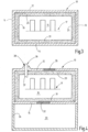
- an explosion-proof housing 10 which comprises a plurality of walls 11, 12, 13, 14, which delimit an interior space 15 that is closed to the outside.
- the base and lid of this housing can be connected to the walls 11 to 14 in a fixed or detachable manner. They continue to be viewed as walls as well.
- components and components such as circuit boards, 17, 18 with electrical components arranged thereon can be arranged, which can form ignition sources.
- open-pored material 19, 20 is arranged, for example in the form of plates, bodies or mats, which completely or partially covers the respective wall 11, 12.
- the open-pored material is preferably arranged directly against the respective wall 11, 12 and is further preferably connected to it.
- the connection can be made by full-surface gluing, welding or other connecting measures that lead to a cohesive partial or full-surface connection.
- the open-pored material 19, 20 can be held in a receptacle, which is formed, for example, by a grid structure 21.
- the grid structure 21 can be a perforated metal housing, a wire mesh, a cage or the like, which is connected to the housing 10 and keeps the open-pored material 19, 20 away from the rest of the interior 15.
- the open-pored material 19, 20 has surfaces 22, 23 on its side facing the interior 15, which, as shown, are arranged at an angle to one another that is smaller than 180 °.
- a further section 24 of open-pored material is arranged opposite the open-pored material 19.
- This can be the same or a different open-pored material as the materials 19, 20. It can have the same or different thickness.
- the open-pored materials 19, 20 can have the same or different thicknesses.
- the material 24 has a surface 25 facing the interior 15, which is opposite the surface 22 and which is arranged at an angle of, for example, 90° to the surface 23.
- the open-pored material 19, 20 and/or 24 forms an inner Pressure relief device.
- a further internal pressure relief device can be formed by an open-pored body 26, which is arranged freely on at least four, preferably on five or six sides, ie not resting against one of the walls of the wall arrangement, in the interior 15 of the housing 10.
- the open-pored body 26 is preferably a fibrous body, the fibers of which are connected to one another by a binding agent.
- Figure 2 schematically illustrates a section of the body 26. As can be seen, several fibers 27 are intertwined with one another in a spatially disordered arrangement and are connected by binding agents 28 at at least some of their crossing points.
- the fibers can be metal fibers or mineral fibers, in particular glass fibers, quartz fibers, stone fibers, ceramic fibers.
- the binder 28 can be a synthetic resin, in particular a phenolic resin. The resin content is so low that the pores between the fibers 27 remain open. However, it is so large that the open-pored body 26 has considerable dimensional stability, so that it does not ignite an explosion in the interior 15 is dissolved and if possible no or at most a harmless quantum of fibers is released.
- the fibers 27 can be the same fibers that are also used for the open-pored material 19, 20, 24. This can also be pre-compacted and, if desired, also provided with binder.
- the housing 10 is provided with at least one pressure relief device 30 and a possible additional pressure relief device 29.
- Both pressure relief devices 29, 30 are porous, gas-permeable bodies with a gap width and gap length that prevent flame spread.
- the pressure relief device 29 is arranged in a section of the wall 14 of the housing 10 that is free of porous material.
- the pressure relief device 30 is covered by the open-pored material 25 when viewed from the interior 15. However, this does not prevent the passage of gas.
- Figure 3 illustrates a modified embodiment of the housing 10 according to the invention.
- the housing 10 points Figure 3 porous material 19, 20, 25, 31 on all four walls 11, 12, 13, 14 of the housing and optionally additionally on the bottom and / or the lid, not shown.
- the open-pored material 19, 20, 25, 31 forms a locally interrupted or uninterrupted layer running along the walls, which catches a flame front ignited in the interior 15 and absorbs the resulting pressure wave.
- the housing 10 illustrated is one on the housing 10 Figure 3 building embodiment.
- This housing has a Pressure relief device 32, which is designed to be flameproof and is arranged in the wall 14, to which an expansion volume 33 is connected.
- This can be separated from the environment by a partial housing 34 and closed off from it, or it can also have openings through which it is connected to the environment.
- a pressure relief body 35 can be provided in the wall 12, which enables pressure relief towards the environment.
- the flameproof pressure relief body 35 can in turn be covered on the inside by the porous material 20 or can be exposed.
- a feedthrough device 36 can be provided, for example by guiding a shaft 37 through the housing wall 12.
- the shaft 37 can define a flameproof gap 38 with the housing wall 12. The shaft 37 can be guided through the open-pored material 20 and transmit movements between elements outside the housing 10 to elements inside the housing 10.
- the housing 10 according to the invention can be provided on the inside with a lining made of open-pored material, preferably comprising at least two sides of the housing 10. Additionally or alternatively, a molded body made of open-pored material, in particular bonded fiber material, can be arranged in the housing.
Landscapes
- Engineering & Computer Science (AREA)
- Microelectronics & Electronic Packaging (AREA)
- Power Engineering (AREA)
- Installation Of Indoor Wiring (AREA)
- Battery Mounting, Suspending (AREA)
- Casings For Electric Apparatus (AREA)
- Filling Or Discharging Of Gas Storage Vessels (AREA)
- Aiming, Guidance, Guns With A Light Source, Armor, Camouflage, And Targets (AREA)
- Buildings Adapted To Withstand Abnormal External Influences (AREA)
- Laminated Bodies (AREA)
- Filtering Materials (AREA)
- Structure Of Emergency Protection For Nuclear Reactors (AREA)
- Catching Or Destruction (AREA)
- Respiratory Apparatuses And Protective Means (AREA)
Description
- Gegenstand der Erfindung ist ein explosionsgeschütztes Gehäuse, insbesondere ein ein- oder mehrkammeriges Gehäuse der Schutzart Ex-d.
- In explosionsgefährdeten Bereichen werden häufig Gehäuse der Schutzart Ex-d eingesetzt. Solche Gehäuse sind so widerstandsfähig ausgebildet, dass sie einer in ihrem Innenraum stattfindenden Zündung eines explosiven Gasgemisches und der infolge der eintretenden Explosion darauf folgenden Druckerhöhung standhalten. Außerdem sind die Gehäuse so gestaltet, dass aus Ihnen keine Flammen oder glühende, als Zündquellen wirkende Partikel nach außen gelangen können. Sollten Spalte vorhanden sein, müssen diese eine Mindestlänge aufweisen und dürfen eine Höchstweite nicht überschreiten. Vorhandene Gehäuseöffnungen sind mit Druckentlastungskörpern versehen, die auch als Flammenschutzfilter bezeichnet werden und verhindern, dass eine im Gehäuse gezündete Flamme nach außen dringt und in der Umgebung vorhandenes explosionsfähiges Gemisch zündet wobei sie andererseits einen Druckausgleich mit der Umgebung bewirken.
- Die
DD 261 063 A3 - Die
DE 198 60 286 B4 offenbart ein für einen Bildschirm vorgesehenes Gehäuse, dessen Innenraum teilweise mit einem porösen Dämpfungsmaterial zur Senkung des Explosionsdrucks gefüllt ist. Das Material weist eine Vielzahl im Querschnitt kleiner, nicht geschlossener, sondern durchgehender Kanäle in Form von Poren oder Spalten auf. Der Explosionsdruck soll dadurch auf lediglich etwa 10 Prozent des Explosionsdrucks gemindert werden, das sonst in dem leeren Gehäuse auftreten würde. - Weiter schlägt die
DE 10 2014 206433 B3 die Anordnung eines Tablett-Computers in einem mit einer Glasscheibe versehenen explosionssicheren Gehäuse vor, wobei in dem Tablett-Computer ein Dämpfungselement aus offenporiger Steinwolle, Quarzwolle, Glaswolle, Metallschaum oder dergleichen angeordnet ist. - Bei den bekannten Gehäusen mit Körpern aus offenporigem Material handelt es sich teilweise um Speziallösungen, die relativ raumgreifend sind und/oder sehr an die speziellen Gegebenheiten, wie beispielsweise Tablett-Computer, angepasst sind.
- Die
DE 10 2013 109 259 A1 beschreibt dagegen ein explosionsgeschütztes Gehäuse der Schutzart druckfeste Kapselung (Ex-d), in dessen Gehäusewand ein poröser Druckentlastungskörper vorgesehen ist, durch den ein im Gehäuse aufgebauter Explosionsdruck nach außen dringen kann. Dieses Prinzip nutzen auch die Gehäuse gemäß derUS 4,180,177 sowie nach derDE 10 2010 016 782 B4. - Weiter ist aus der
DE 2009 025 296 A1 ein Gehäuse bekannt, mit dem elektrische Geräte in explosionsgefährdeten Umgebungen sicher betrieben werden sollen. Das Gehäuse soll sicherstellen, dass im Falle einer Explosion innerhalb des Gehäuses keine Gefährdungen wie zum Beispiel Funken an die explosionsgefährdete Umgebung übergehen. Zur Verringerung des Gewichts und der Wandstärke des Gehäuses unter gleichzeitigen Erfüllung der Explosionsschutzanforderungen wird vorgeschlagen das Gehäuse innen ganz oder teilweise mit energieabsorbierendem Material auszukleiden. Als geeignete Materialien werden metallische Wabenstrukturen, poröse organische Füllstoffe, wie beispielsweise Maisspindeln oder organische Fasern, wie zum Beispiel mit epoxidharzverklebe Flachsfasern angegeben. Mit diesem Material werden eventuelle Öffnungen und Flammenwege überdeckt, womit eine Doppelfunktion erfüllt werden soll, nämlich die Kühlung des ausströmenden heißen Gases und die Dämpfung der Druck und Stoßwelle. - Die Anordnung von druckwellenabsorbierendem Material in einem ansonsten geschlossenen Gehäuse ist auch aus der
DE 20 2015 005 015 U1 bekannt. Das dort vorgestellte Gehäuse ist nach außen hin geschlossen. Innen weist es ein oder zwei stoßwellenabsorbierende Elemente auf, die beispielsweise an zueinander im Winkel stehenden Wänden oder frei dem Raum durchquerend angeordnet sind. - Derartige Druckentlastungskörper unterliegen bei Anordnung solcher Gehäuse in widriger Umgebung der Verschmutzung oder bei Wetterbeaufschlagung der Verkeimung, Vereisung und/oder Korrosion. Die Berücksichtigung solcher Umstände führt zu einer Erhöhung des Aufwands.
- Es ist Aufgabe der Erfindung, ein Konzept für ein explosionsgeschütztes Gehäuse anzugeben, das vielseitig anwendbar und wenig aufwendig ist.
- Diese Aufgabe wird mit dem Gehäuse nach Anspruch 1 gelöst. Weitere bevorzugte Ausführungsformen sind in den abhängigen Ansprüchen definiert.
- Das erfindungsgemäße Gehäuse umfasst eine Wandanordnung mit mehreren Wänden, die einen Innenraum umschließen. An wenigstens zwei der Wände der Wandanordnung ist ein offenporiges Material angeordnet. Durch die Anordnung des offenporigen Materials an zwei verschiedenen zum Beispiel einander gegenüberliegenden oder im Winkel zueinander stehenden Wänden wird eine in dem Gehäuse ausgelöste Druckwelle besonders effizient vernichtet. Dies gilt sowohl, wenn jede der mit offenporigen Material versehenen Wände vollflächig mit diesem Material versehen ist, wie auch wenn sich bei einer oder mehreren der mit dem Material versehenen Wände das Material lediglich über einen Teilbereich der betroffenen Wand erstreckt.
- Die Nutzung wenigstens zweier oder mehrerer Wandflächen zur Anbringung von offenporigem Material, das eine darauf auftreffende oder daran entlanglaufende Druckwelle dämpft, führt zu einer großen aktiven Dämpfungsfläche und somit zu einer hohen Dämpfungswirkung, auch wenn lediglich relativ dünne Lagen aus offenporigem Material verwendet werden. Damit wird der für die Aufnahme von Komponenten zur Verfügung stehende Teil des Innenraums des Gehäuses durch das offenporige Material nur wenig reduziert. In dem Gehäuse können die Wände teilweise oder komplett mit porösem Material ausgekleidet sein. Die porösen Materialien wirken einerseits als ein nicht zündfähiges Entlastungsvolumen und andererseits als Löschvolumen für eine eindringende Flammenfront. Eine kugelförmige Explosionsfront wird durch die Auskleidung sofort schnellstmöglich großflächig aufgenommen, wobei eine Kühlung und Aufnahme unverbrannter Gase bewirkt wird. Damit wird zum einen die Menge des an der Verbrennung bzw. Explosion teilnehmenden Gases reduziert und andererseits durch Gaskühlung der Druck gemindert. Durch vollständige Auskleidung des Gehäuses innen mit dem offenporigen Material wird ein optimaler Flächen-/Volumen-Faktor für das Gehäuse erhalten.
- Durch die Anordnung des offenporigen Materials, vorzugsweise ausschließlich an den Wänden, wird ein großer zusammenhängender Einbauraum für Betriebsmittel, Schalter und dergleichen erhalten.
- Vorzugsweise ist das offenporige Material unmittelbar an den wenigstens zwei Wänden anliegend angeordnet. Die dadurch gegebene Wärmeübertragung zwischen dem offenporigen Material und der Gehäusewand kühlt das offenporige Material, so dass dieses einen hohen druckreduzierenden Effekt aufweist. Die Gehäusewand bildet ein an das offenporige Material thermisch angeschlossenen Wärmespeicher.
- Das offenporige Material kann vollflächig, stoffschlüssig oder lediglich stellenweise stoffschlüssig mit den Wänden des druckfesten Gehäuses verbunden sein. Dazu kann das poröse Material mit den Wänden verschweißt oder, wenn das Gehäuse im Gussverfahren hergestellt wird, durch Einbringen in die Gussform durch Urformen mit den Gehäusewänden verbunden sein. Andere mechanische form- und/oder stoffschlüssige Verbindungsmöglichkeiten können genutzt werden. Beispielsweise kann das offenporige Material von einer Gitterstruktur eingefasst sein, die mit der Wandanordnung verbunden ist. Die Gitterstruktur kann ein Drahtgitter, ein Lochblech, ein Kunststoffgitter oder dergleichen sein.
- Das poröse Material ist vorzugsweise als Platte oder Matte im Wesentlichen gleichbleibender Dicke ausgebildet, so dass die wandabgewandte Fläche parallel oder im spitzen Winkel zu dieser verlaufen angeordnet ist. Damit stehen sich im Innenraum wenigstens zwei Flächen des offenporigen Materials im Wesentlichen gegenüber oder im Winkel zueinander. Beides führt zu einer wirksamen Dämpfung einer dynamisch durchlaufenden Flammenfront.
- An von offenporigem Material bedeckten Stellen der Wand ist wenigstens ein Druckentlastungskörper angeordnet. Während das offenporige Material selbst keine Sicherheit gegen Flammendurchschlag bietet, wird die Flammendurchschlagsicherheit nach außen durch den oder die Druckentlastungskörper erbracht. Das offenporige Material kann durch einen oder mehrere Körper aus Metallschaum, aus gesinterten Metallpartikeln, Metallfasern, insbesondere Edelstahlwolle, andere Metallfasern, mineralische Fasern wie Glasfasern, Steinwollfasern, Quarzfasern und ähnlichem gebildet sein. Bei den Körpern aus Fasermaterial kann es sich um nadelgefilzte Anordnungen, d.h. ein Wirrfasergelege mit verfilzten, stofflich jedoch nicht aneinander gebundenen Fasern handeln. Bedarfsweise kann auch eine stoffliche Bindung der Fasern untereinander, z.B. durch ein Bindemittel oder durch Sintern vorhanden sein. Die Fasern führen zu einer Kühlung der aufgenommenen Druckwelle durch Wärmeaufnahme und zu einer Vernichtung der kinetischen Energie der Druckwelle durch innere Reibung der Fasern aneinander. Bevorzugt wird ein Material mit hoher Wärmespeicherkapazität, wie Steinwolle oder Keramikwolle.
- Das Fasermaterial des offenporigen Materials kann zu einem Körper in Gestalt von Platten, Quadern oder anderen Formen vorgepresst sein, die in das Gehäuse eingelegt, eingeklebt oder eingeschraubt werden können oder die durch ein Gestell gehalten sind. Die Verdichtung des Faserkörpers ist jedoch vorzugsweise so schwach, dass Abstände und Spalte der porösen Materialen wenigstens an einigen Stellen oberhalb der Grenzspaltenweite des klassischen Explosionsschutzes liegen, d.h. Kühlungseffekt, Strömungseffekt oder sonstige kinetische Effekte, die eine Zündung von in dem Material vorhandenem Gas oder ein Durchlaufen der Flammenfront durch das Material verhindern könnten, sind nicht oder nicht durchgängig vorhanden. Insbesondere wenn das offenporige Material eine hohe Wärmekapazität aufweist, wie es beispielsweise bei Glasfasern, Quarzfasern, Keramikfasern, Steinfasern der Fall ist, wird dennoch eine hohe Druckreduktion erreicht.
- Das offenporige Material kann auch durch anorganische oder organische Bindemittel soweit gebunden sein, dass ein offenporiger formstabiler Körper entsteht. Dieser muss nicht zwangsläufig an die Wand anschließen. Ein solcher vorgeformter gebundener Faserkörper, kann auch in dem Gehäuse von vier, fünf oder sechs Seiten zugänglich angeordnet sein. Er wirkt auch ohne Wandanschluss druckmindernd und kann alternativ oder zusätzlich zu den vorstehend beschriebenen Auskleidungen des Gehäuses mit offenporigem Material Anwendung finden.
- Beispiele ergeben sich aus Ansprüche, Zeichnungen und der Beschreibung. Die Erfindung wird durch die beigefügten Ansprüche definiert. Die Zeichnungen zeigen:
-
Figur 1 ein erfindungsgemäßes Gehäuse mit verschiedenen Maßnahmen zur Druckreduktion, in schematisierter Darstellung; -
Figur 2 einen Ausschnitt aus einem druckreduzierenden offenporigen Körper des Gehäuses nachFigur 1 ; -
Figur 3 und 4 weitere Ausführungsformen des erfindungsgemäßen Gehäuses jeweils, in schematisierter Querschnittsdarstellung. - In
Figur 1 ist ein explosionsgeschütztes Gehäuse 10 veranschaulicht, das mehrere Wänden 11, 12, 13, 14 umfasst, die einen nach außen abgeschlossenen Innenraum 15 umgrenzen. Die Wände 11 bis 14 bilden zusammen mit einem nicht weiter veranschaulichten Boden und einem Deckel eine Wandanordnung 16. Boden und Deckel diese Gehäuses können mit den Wänden 11 bis 14 fest oder auch lösbar verbunden sein. Sie werden weiterhin ebenfalls als Wände angesehen. - In dem Innenraum 15 können Bauelemente und Komponenten wie beispielsweise Leiterplatten, 17, 18 mit darauf angeordneten elektrischen Bauelementen angeordnet sein, die Zündquellen bilden können.
- An wenigstens zwei Wänden 11, 12 des Gehäuses 10 ist offenporiges Material 19, 20 zum Beispiel in Gestalt von Platten, Körpern oder Matten angeordnet, das die jeweilige Wand 11, 12 jeweils ganz oder teilweise bedeckt. Das offenporige Material ist dabei vorzugsweise unmittelbar an die jeweilige Wand 11, 12 anliegend angeordnet und weiter vorzugsweise mit dieser verbunden. Die Verbindung kann durch vollflächiges Verkleben, Verschweißen oder durch andere Verbindungsmaßnahmen, erfolgen, die zu einer stoffschlüssigen teil- oder vollflächigen Verbindung führen. Alternativ oder zusätzlich kann das offenporige Material 19, 20 in einer Aufnahme gehalten sein, die beispielsweise durch eine Gitterstruktur 21 gebildet ist. Die Gitterstruktur 21 kann ein Lochblechgehäuse, ein Drahtgitter, ein Käfig oder dergleichen sein, der mit dem Gehäuse 10 verbunden ist und das offenporige Material 19, 20 von dem sonstigen Innenraum 15 fernhält.
- Das offenporige Material 19, 20 weist an seiner jeweils zu dem Innenraum 15 hin weisenden Seite Flächen 22, 23 auf, die wie dargestellt in einem Winkel zueinander angeordnet sind, der kleiner als 180° ist.
- Alternativ oder zusätzlich zu dem offenporigen Material 20 ist den offenporigem Material 19 gegenüberliegend ein weiterer Abschnitt 24 offenporigen Materials angeordnet. Dieses kann das gleiche oder ein anderes offenporiges Material wie die Materialien 19, 20 sein. Es kann die gleiche oder eine unterschiedliche Dicke aufweisen. Ebenso können die offenporigen Materialien 19, 20 gleiche oder unterschiedliche Dicken aufweisen. Das Material 24 weist eine dem Innenraum 15 zugewandte Fläche 25 auf, die der Fläche 22 gegenüberliegt und die zu der Fläche 23 im Winkel von z.B. 90° angeordnet ist.
- Das offenporige Material 19, 20 und/oder 24 bildet eine innere
Druckentlastungsvorrichtung. Eine weitere innere Druckentlastungsvorrichtung kann durch einen offenporigen Körper 26 gebildet sein, der an wenigstens vier, vorzugsweise an fünf oder sechs Seiten frei, d.h. nicht an einer der Wände der Wandanordnung anliegend, in dem Innenraum 15 des Gehäuses 10 angeordnet ist. Der offenporige Körper 26 ist vorzugsweise ein Faserkörper, dessen Fasern durch ein Bindemittel untereinander verbunden sind.Figur 2 veranschaulicht schematisiert einen Ausschnitt aus dem Körper 26. Wie ersichtlich sind mehrere Fasern 27 in räumlich ungeordneter Anordnung miteinander verschlungen und an wenigstens einigen ihrer Kreuzungsstellen durch Bindemittel 28 verbunden. Bei den Fasern kann es sich um Metallfasern oder mineralische Fasern insbesondere Glasfasern, Quarzfasern, Steinfasern, Keramikfasern, handeln. Das Bindemittel 28 kann ein Kunstharz, insbesondere ein Phenolharz, sein. Der Harzanteil ist so gering, dass die zwischen den Fasern 27 vorhandenen Poren offen bleiben. Er ist jedoch so groß, dass der offenporige Körper 26 eine erhebliche Formstabilität hat, so dass er bei Zündung einer Explosion in dem Innenraum 15 nicht aufgelöst wird und möglichst keine oder allenfalls ein unschädliches Quantum Fasern freisetzt. - Bei den Fasern 27 kann es sich um die gleichen Fasen handeln, die auch für das offenporige Material 19, 20, 24 Anwendung findet. Dieses kann ebenfalls vorverdichtet und, falls gewünscht, auch mit Bindemittel versehen sein.
- Das Gehäuse 10 ist mit wenigstens einer Druckentlastungsvorrichtung 30 und einer eventuellen zusätzlichen Druckentlastungsvorrichtung 29 versehen. Beide Druckentlastungsvorrichtungen 29, 30 sind poröse gasdurchlässige Körper mit einer Spaltweite und Spaltlänge, die einen Flammendurchschlag verhindert. Die Druckentlastungsvorrichtung 29 ist in einem von porösem Material freien Abschnitt der Wand 14 des Gehäuses 10 angeordnet. Die Druckentlastungsvorrichtung 30 ist von dem Innenraum 15 her gesehen durch das offenporige Material 25 bedeckt. Dieses hindert den Gasdurchtritt jedoch nicht.
-
Figur 3 veranschaulicht eine abgewandelte Ausführungsform des erfindungsgemäßen Gehäuses 10. Die vorige Beschreibung gilt unter Verwendung der bereits eingeführten Bezugszeichen entsprechend. Im Unterschied zu dem zuvor beschriebenen Gehäuses 10 weist das Gehäuse 10 nachFigur 3 poröses Material 19, 20, 25, 31 an allen vier Wänden 11, 12, 13, 14 des Gehäuses und optional zusätzlich an dem nicht veranschaulichten Boden und/oder dem Deckel auf. Das offenporige Material 19, 20, 25, 31 bildet eine an den Wänden entlang führende lokal unterbrochener oder auch ununterbrochene Schicht, die eine in dem Innenraum 15 gezündete Flammenfront auffängt und die entstehende Druckwelle absorbiert. - Bei dem in
Figur 4 veranschaulichten Gehäuse 10 handelt es sich um eine auf dem Gehäuse 10 nachFigur 3 aufbauende Ausführungsform. Dieses Gehäuse weist eine Druckentlastungsvorrichtung 32 auf, die flammendurchschlagsicher ausgebildet und in der Wand 14 angeordnet ist, an die sich ein Expansionsvolumen 33 anschließt. Dieses kann durch ein Teilgehäuse 34 von der Umgebung getrennt und gegen diese abgeschlossen sein oder auch Öffnungen aufweisen, über die es mit der Umgebung in Verbindung steht. - Zusätzlich oder alternativ kann in der Wand 12 ein Druckentlastungskörper 35 vorgesehen sein, der eine Druckentlastung zur Umgebung hin ermöglicht. Der flammendurchschlagsichere Druckentlastungskörper 35 kann innen wiederum von dem porösen Material 20 überdeckt sein oder freiliegen. Außerdem kann eine Durchführungseinrichtung 36 vorgesehen sein, indem beispielsweise eine Welle 37 durch die Gehäusewand 12 geführt ist. Dazu kann die Welle 37 mit der Gehäusewand 12 einen zünddurchschlagsicheren Spalt 38 festlegen. Die Welle 37 kann durch das offenporige Material 20 geführt sein und Bewegungen zwischen Elementen außerhalb des Gehäuses 10 zu Elementen innerhalb des Gehäuses 10 übertragen.
- Das erfindungsgemäße Gehäuse 10 kann zur Reduktion von internem Explosionsdruck innen mit einer vorzugsweise wenigstens zwei Seiten des Gehäuses 10 umfassenden Auskleidung aus offenporigen Material versehen sein. Zusätzlich oder alternativ kann in dem Gehäuse ein Formkörper aus offenporigem Material insbesondere gebundenem Fasermaterial angeordnet sein.
-
10 Gehäuse 11 - 14 Wände 15 Innenraum 16 Wandanordnung 17, 18 Leiterplatten 19, 20 offenporiges Material 21 Gitterstruktur 22, 23 Flächen des offenporigen Materials 24 Abschnitt des offenporigen Materials 25 Fläche 26 offenporiger Körper 27 Fasern 28 Bindemittel 29, 30 Druckentlastungsvorrichtung 31 offenporiges Material 32 Druckentlastungskörper 33 Expansionsvolumen 34 Teilgehäuse 35 Druckentlastungskörper
Claims (11)
- Gehäuse (10) der Schutzart ex-d,mit einer Wandanordnung (16), die mehrere Wände (11, 12, 13, 14) aufweist,die einen Innenraum (15) umschließen,wobei wenigstens zwei der Wände (11, 12) der Wandanordnung (16) mit einem offenporigen Material (19, 20) ohne Sicherheit gegen Flammendurchschlag versehen sind, und dadurch ein das offenporige Material (19, 20) tragender Bereich der wenigstens zwei der Wände (16) definiert ist,dadurch gekennzeichnet, dass das Gehäuse (10) mit wenigstens einer durch einen porösen, gasdurchlässigen Körper gebildeten Druckentlastungseinrichtung (29 und/oder 30) versehen ist, die eine Strömungsverbindung zwischen dem Innenraum (15) und der Umgebung ermöglicht, dass die wenigstens eine Druckentlastungseinrichtung (29 und/oder 30)ein gasdurchlässiger Körper (29 und/oder 30) mit einer Spaltweite und Spaltlänge ist, die einen Flammendurchschlag verhindert, unddass der das offenporige Material (19, 20) tragende Bereich der wenigstens zwei der Wände (11, 21) wenigstens eine Öffnung aufweist, die mit dem gasdurchlässigen, flammendurchschlagsicheren Körper (30) versehen ist.
- Gehäuse nach Anspruch 1, wobei das offenporige Material (10, 20) unmittelbar an den beiden der wenigstens zwei der Wänden (11, 12) anliegend angeordnet ist.
- Gehäuse nach einem der vorstehenden Ansprüche, wobei das Material (19, 20) an jeder der wenigstens zwei der Wände (11, 12), an denen es angebracht ist, eine wandabgewandte Fläche (22, 23) aufweist, die dem Innenraum (15) zugewandt ist.
- Gehäuse nach Anspruch 3, wobei die wandabgewandte Fläche (22, 23) parallel zu der jeweiligen Wand der wenigstens zwei der Wände (11, 12) oder im spitzen Winkel zu dieser verlaufend angeordnet ist.
- Gehäuse nach einem der vorstehenden Ansprüche, wobei das offenporige Material (19, 20; ein Fasermaterial ist.
- Gehäuse nach einem der vorstehenden Ansprüche, wobei das offenporige Material (19, 20) von einer Gitterstruktur (21) eingefasst ist, die mit der Wandanordnung (16) verbunden ist.
- Gehäuse nach einem der vorstehenden Ansprüche, wobei der das offenporige Material (19, 20) tragende Bereich der wenigstens zwei der Wände (11, 21) geschlossen ausgebildet ist oder lediglich flammendurchschlagsichere Spalte (38) aufweist.
- Gehäuse nach Anspruch 1, wobei in dem Innenraum ein offenporiger Körper (26) angeordnet ist und dass der offenporige Körper (26) aus einer durch ein Bindemittel (28) formhaltig gebunden, metallischen oder mineralischen Faseranordnung besteht.
- Gehäuse nach Anspruch 8, wobei die Faseranordnung (26) Metallfasern, Glasfasern, Quarzfasern, Gesteinsfasern, Keramikfasern oder ein Gemisch aus diesen aufweist und dass das Bindemittel ein Kunstharz ist.
- Gehäuse nach Anspruch 8, wobei das Bindemittel (28) ein Kunstharz ist.
- Gehäuse nach Anspruch 8, wobei das Bindemittel (28) ein organischer Binder ist.
Applications Claiming Priority (2)
| Application Number | Priority Date | Filing Date | Title |
|---|---|---|---|
| DE102017112150.1A DE102017112150B4 (de) | 2017-06-01 | 2017-06-01 | Explosionssicheres Gehäuse mit innerer Druckreduzierung |
| PCT/EP2018/057338 WO2018219517A1 (de) | 2017-06-01 | 2018-03-22 | Explosionssicheres gehäuse mit innerer druckreduzierung |
Publications (2)
| Publication Number | Publication Date |
|---|---|
| EP3632194A1 EP3632194A1 (de) | 2020-04-08 |
| EP3632194B1 true EP3632194B1 (de) | 2024-03-13 |
Family
ID=61800511
Family Applications (2)
| Application Number | Title | Priority Date | Filing Date |
|---|---|---|---|
| EP18713624.7A Active EP3632194B1 (de) | 2017-06-01 | 2018-03-22 | Explosionssicheres gehäuse mit innerer druckreduzierung |
| EP18807640.0A Active EP3769595B1 (de) | 2017-06-01 | 2018-11-29 | Gehäuse mit innerer druckreduzierung |
Family Applications After (1)
| Application Number | Title | Priority Date | Filing Date |
|---|---|---|---|
| EP18807640.0A Active EP3769595B1 (de) | 2017-06-01 | 2018-11-29 | Gehäuse mit innerer druckreduzierung |
Country Status (5)
| Country | Link |
|---|---|
| US (2) | US11627674B2 (de) |
| EP (2) | EP3632194B1 (de) |
| CN (2) | CN110915311B (de) |
| DE (1) | DE102017112150B4 (de) |
| WO (2) | WO2018219517A1 (de) |
Families Citing this family (7)
| Publication number | Priority date | Publication date | Assignee | Title |
|---|---|---|---|---|
| EP3917297B1 (de) | 2020-05-25 | 2025-03-19 | ABB Schweiz AG | Elektronikgehäuseanordnung für eine elektrische vorrichtung und elektrische vorrichtung |
| CN115206746A (zh) * | 2022-08-11 | 2022-10-18 | 西安中熔电气股份有限公司 | 一种激励熔断器嵌套结构 |
| CN116469735A (zh) * | 2023-05-23 | 2023-07-21 | 佛山市高明毅力温控器有限公司 | 一种防爆型过温过流保护器密封结构 |
| DE102023132879B3 (de) | 2023-08-31 | 2024-09-26 | Burg-Wächter Kg | Verwendung eines Absorberelements und Gebäuderaum mit einer Geldausgabe - beziehungsweise Geldeingabevorrichtung |
| WO2026018057A1 (en) * | 2024-07-17 | 2026-01-22 | Abb Schweiz Ag | Porous linings to reduce peak explosion pressure inside a flame-proof enclosure of a synchronous reluctance motor |
| WO2026047383A1 (en) * | 2024-08-30 | 2026-03-05 | Abb Schweiz Ag | Electric motor with explosion inhibiting material |
| WO2026053010A1 (en) * | 2024-09-06 | 2026-03-12 | Abb Schweiz Ag | Porous, flame-quenching linings in flame paths of motor enclosures to reduce peak explosion pressure and prevent flame transmission |
Citations (1)
| Publication number | Priority date | Publication date | Assignee | Title |
|---|---|---|---|---|
| DE102013109259A1 (de) * | 2013-08-27 | 2015-03-05 | R.Stahl Schaltgeräte GmbH | Druckentlastungsvorrichtung für ein explosionsgeschütztes Gehäuse und Verfahren zu deren Herstellung |
Family Cites Families (38)
| Publication number | Priority date | Publication date | Assignee | Title |
|---|---|---|---|---|
| US3607604A (en) * | 1969-11-19 | 1971-09-21 | Robert D Nava | Flame arrester and pressure relief |
| US4180177A (en) | 1979-04-04 | 1979-12-25 | The United States Of America As Represented By The Secretary Of The Interior | Pressure vent for explosion-proof electrical enclosures |
| DD261063A3 (de) | 1984-11-19 | 1988-10-19 | Bergbausicherheit Inst | Anordnung zum reduzieren von explosionsdruecken in geschlossenen raeumen |
| AT391283B (de) * | 1987-09-04 | 1990-09-10 | Gass Helmut | Verfahren zur herstellung eines explosionsschutzes sowie explosionsschutz fuer einen behaelter fuer entflammbare medien |
| US5500037A (en) * | 1988-12-06 | 1996-03-19 | Alhamad; Shaikh G. M. Y. | Impact Absorber |
| JP2883225B2 (ja) | 1991-07-10 | 1999-04-19 | 三菱電機株式会社 | 耐熱耐圧形永久磁石同期電動機 |
| DE4313776C1 (de) * | 1993-04-27 | 1994-10-27 | Stahl R Schaltgeraete Gmbh | Belüftungs- und Entwässerungsstutzen für elektrotechnische Gehäuse |
| DE19826911C2 (de) * | 1998-06-17 | 2000-10-19 | Bundesrep Deutschland | Verfahren zur Führung von im Innern eines Gehäuses gebildeten Explosionsgasen durch zünddurchschlagsicher ausgebildete Spalte und explosionsgeschütztes Gehäuse |
| DE19860283B4 (de) | 1998-12-19 | 2005-09-15 | Auergesellschaft Gmbh | Innenmaske für eine Atemschutzmaske |
| DE19860383B4 (de) | 1998-12-28 | 2005-06-09 | Bartec Gmbh | Bildschirm |
| DE20208576U1 (de) * | 2002-06-03 | 2002-08-22 | Brilex Gesellschaft für Explosionsschutz mbH, 59929 Brilon | Druckentlastungsvorrichtung mit Berstscheibe |
| DE10245307A1 (de) * | 2002-09-27 | 2004-04-08 | Brilex Gesellschaft für Explosionsschutz mbH | Flammensperrender Festkörper |
| US7130176B2 (en) * | 2004-12-23 | 2006-10-31 | Lucent Technologies Inc. | Protective enclosures and related methods |
| DE102005042565B4 (de) * | 2005-09-08 | 2009-08-27 | Fhf Funke + Huster Fernsig Gmbh | Gehäuse für ein elektrisch betriebenes Gerät |
| DE202007003938U1 (de) * | 2007-03-17 | 2007-06-06 | Burg-Wächter Kg | Behälter zur Aufbewahrung von Gegenständen |
| DE102009025296A1 (de) | 2009-06-15 | 2010-12-23 | Winfried Jung | Ausführung eines explosionsgeschützten Raums, vorzugsweise zur Aufnahme von nicht ausreichend geschützter Komponenten |
| DE102010018784A1 (de) * | 2010-04-29 | 2011-11-03 | R.Stahl Schaltgeräte GmbH | Leiterplatte mit druckfest gekapseltem Teilgehäuse |
| DE102010016782B4 (de) | 2010-05-04 | 2016-12-08 | R.Stahl Schaltgeräte GmbH | Druckentlastungsvorrichtung für druckfest gekapselte Gehäuse |
| EP2583733B1 (de) | 2010-06-16 | 2021-05-05 | Nitto Denko Corporation | Wasserdichter und luftdurchlässiger filter und seine verwendung |
| CN102523714B (zh) | 2011-12-21 | 2014-10-15 | 刘立文 | 一种基于矿用电机的防爆控制器 |
| DE102013204585A1 (de) * | 2013-03-15 | 2014-09-18 | Robert Bosch Gmbh | Batteriepack mit Überdruckablassvorrichtung und Partikelabscheider |
| DE102013006738B4 (de) * | 2013-04-19 | 2014-12-31 | Peter Reitinger | Druckentlastungsvorrichtung |
| RU133278U1 (ru) | 2013-05-22 | 2013-10-10 | Открытое акционерное общество "Научно-производственное объединение "Центральный научно-исследовательский институт технологии машиностроения" (ОАО НПО "ЦНИИТМАШ") | Взрывозащитный контейнер |
| DE102013109261A1 (de) * | 2013-08-27 | 2015-03-05 | R.Stahl Schaltgeräte GmbH | Druckentlastungsvorrichtung für druckfest gekapselte Gehäuse mit einem porösen Körper mit Übermaßpassung |
| DE102013109260A1 (de) * | 2013-08-27 | 2015-03-05 | R.Stahl Schaltgeräte GmbH | Gehäuseteil für ein explosionsgeschütztes Gehäuse mit einem porösen Körper |
| DE102014206436B3 (de) * | 2014-04-03 | 2015-08-20 | Ecom Instruments Gmbh | Geräte-Anordnung, insbesondere zur Verwendung in einem explosionsgefährdeten Bereich |
| DE102014206433B3 (de) | 2014-04-03 | 2015-08-20 | Ecom Instruments Gmbh | Geräte-Anordnung, insbesondere zur Verwendung in einem explosionsgefährdeten Bereich |
| CN203801184U (zh) | 2014-05-07 | 2014-08-27 | 郑州鸿浩信息技术有限公司 | 防爆智能中控仪及其防爆壳体 |
| DE102014110654A1 (de) | 2014-07-29 | 2016-02-04 | Genius Patentverwertung Gmbh & Co. Kg | Vorrichtung und Verfahren zum Transport von galvanischen Zellen |
| US10745185B2 (en) * | 2014-08-26 | 2020-08-18 | Carl Gehlhausen | Flame retardant shipping container |
| DE102015206355A1 (de) * | 2015-04-09 | 2016-10-13 | Siemens Aktiengesellschaft | Elektrische Schaltanlage |
| DE202015005015U1 (de) * | 2015-07-17 | 2016-10-18 | Auma Riester Gmbh & Co. Kg | Explosionsgeschütztes Gehäuse |
| DE202016000506U1 (de) * | 2016-01-28 | 2016-05-09 | Rexotec Ag | Druckentlastungsvorrichtung |
| CN110832716B (zh) * | 2017-06-01 | 2022-04-29 | R.施塔尔开关设备有限责任公司 | 焊接的卸压装置 |
| DE102017112153A1 (de) * | 2017-06-01 | 2018-12-06 | R. Stahl Schaltgeräte GmbH | Explosionssicheres Gehäuse mit innerer Druckentlastung |
| US11589470B2 (en) * | 2017-12-04 | 2023-02-21 | Vestas Wind Systems A/S | Pressure relief arrangement with magnets |
| DE102018116397A1 (de) * | 2018-07-06 | 2020-01-09 | R. Stahl Schaltgeräte GmbH | Explosionsgeschütztes Gehäuse mit Druckentlastung |
| DE102019102505B4 (de) * | 2019-01-31 | 2021-09-30 | R. Stahl Schaltgeräte GmbH | Explosionsgeschützte Vorrichtung mit zünddurchschlag-sicherem Gasströmungspfad und Kühlkörper |
-
2017
- 2017-06-01 DE DE102017112150.1A patent/DE102017112150B4/de active Active
-
2018
- 2018-03-22 EP EP18713624.7A patent/EP3632194B1/de active Active
- 2018-03-22 WO PCT/EP2018/057338 patent/WO2018219517A1/de not_active Ceased
- 2018-03-22 US US16/617,921 patent/US11627674B2/en active Active
- 2018-03-22 CN CN201880036062.4A patent/CN110915311B/zh active Active
- 2018-11-29 EP EP18807640.0A patent/EP3769595B1/de active Active
- 2018-11-29 WO PCT/EP2018/083038 patent/WO2019179646A1/de not_active Ceased
- 2018-11-29 CN CN201880091534.6A patent/CN112020901B/zh active Active
- 2018-11-29 US US16/982,965 patent/US12120833B2/en active Active
Patent Citations (1)
| Publication number | Priority date | Publication date | Assignee | Title |
|---|---|---|---|---|
| DE102013109259A1 (de) * | 2013-08-27 | 2015-03-05 | R.Stahl Schaltgeräte GmbH | Druckentlastungsvorrichtung für ein explosionsgeschütztes Gehäuse und Verfahren zu deren Herstellung |
Also Published As
| Publication number | Publication date |
|---|---|
| CN110915311A (zh) | 2020-03-24 |
| US12120833B2 (en) | 2024-10-15 |
| WO2018219517A1 (de) | 2018-12-06 |
| EP3769595A1 (de) | 2021-01-27 |
| DE102017112150B4 (de) | 2019-02-07 |
| US20210020388A1 (en) | 2021-01-21 |
| EP3769595B1 (de) | 2026-03-25 |
| CN112020901A (zh) | 2020-12-01 |
| CN112020901B (zh) | 2023-06-02 |
| US11627674B2 (en) | 2023-04-11 |
| RU2020133786A (ru) | 2022-04-22 |
| EP3632194A1 (de) | 2020-04-08 |
| DE102017112150A1 (de) | 2018-12-06 |
| WO2019179646A1 (de) | 2019-09-26 |
| CN110915311B (zh) | 2021-03-26 |
| RU2019143672A3 (de) | 2021-09-01 |
| RU2019143672A (ru) | 2021-07-09 |
| US20200113076A1 (en) | 2020-04-09 |
Similar Documents
| Publication | Publication Date | Title |
|---|---|---|
| DE102017112150B4 (de) | Explosionssicheres Gehäuse mit innerer Druckreduzierung | |
| EP3729536B1 (de) | Batterie mit einem mehrschichtigen wärmedämmelement | |
| EP2566585B1 (de) | Druckentlastungsvorrichtung mit flammensperre für druckfest gekapselte gehäuse | |
| DE102017112153A1 (de) | Explosionssicheres Gehäuse mit innerer Druckentlastung | |
| EP3631925B1 (de) | Explosionssicheres gehäuse mit innerer druckentlastung | |
| EP3199207B1 (de) | Druckentlastungsvorrichtung, modulare druckentlastungseinheit und brandschutzvorrichtung | |
| DE202023100724U1 (de) | Batteriegehäusedeckel mit Faserverbund mit oxidischer Matrix | |
| EP4057370A2 (de) | Batterieanordnung | |
| DE102016202913A1 (de) | Hitzeschild und Anordnung mit einem derartigen Hitzeschild | |
| DE102005042565B4 (de) | Gehäuse für ein elektrisch betriebenes Gerät | |
| DE19860383B4 (de) | Bildschirm | |
| EP3630303B1 (de) | Gehäuse mit eingegossener druckentlastung | |
| DE3544022C2 (de) | ||
| CH678553A5 (de) | ||
| DE102015215454A1 (de) | Vorrichtung zur Dämpfung von Schall mit einer bekannten Frequenz und einer Amplitude, Kühlungssystem sowie elektrische Anlage mit der Vorrichtung | |
| DE102023103675A1 (de) | Batteriegehausedeckel mit Faserverbund mit oxidischer Matrix | |
| DE202018106804U1 (de) | Aufbewahrungsbehälter und Absorberelement für einen Aufbewahrungsbehälter | |
| DE202011110570U1 (de) | Schredderanlage | |
| WO2019063099A1 (de) | Gehäuse für eine elektronische datenverarbeitungseinheit | |
| DE102014206436B3 (de) | Geräte-Anordnung, insbesondere zur Verwendung in einem explosionsgefährdeten Bereich | |
| RU2779927C2 (ru) | Взрывонепроницаемый корпус с внутренним сбросом давления | |
| DE3527730C1 (de) | Explosionskammer | |
| DE3407346C2 (de) | Anordnung zur Nachrüstung von Tresoren gegen die Einwirkung von Sprengladungen | |
| DE202020103298U1 (de) | Wärmeisolierender Kern für Mehrschichtplatte | |
| DE202006009673U1 (de) | Isolierung |
Legal Events
| Date | Code | Title | Description |
|---|---|---|---|
| STAA | Information on the status of an ep patent application or granted ep patent |
Free format text: STATUS: UNKNOWN |
|
| STAA | Information on the status of an ep patent application or granted ep patent |
Free format text: STATUS: THE INTERNATIONAL PUBLICATION HAS BEEN MADE |
|
| PUAI | Public reference made under article 153(3) epc to a published international application that has entered the european phase |
Free format text: ORIGINAL CODE: 0009012 |
|
| STAA | Information on the status of an ep patent application or granted ep patent |
Free format text: STATUS: REQUEST FOR EXAMINATION WAS MADE |
|
| 17P | Request for examination filed |
Effective date: 20191128 |
|
| AK | Designated contracting states |
Kind code of ref document: A1 Designated state(s): AL AT BE BG CH CY CZ DE DK EE ES FI FR GB GR HR HU IE IS IT LI LT LU LV MC MK MT NL NO PL PT RO RS SE SI SK SM TR |
|
| AX | Request for extension of the european patent |
Extension state: BA ME |
|
| DAV | Request for validation of the european patent (deleted) | ||
| DAX | Request for extension of the european patent (deleted) | ||
| STAA | Information on the status of an ep patent application or granted ep patent |
Free format text: STATUS: EXAMINATION IS IN PROGRESS |
|
| 17Q | First examination report despatched |
Effective date: 20220105 |
|
| RIC1 | Information provided on ipc code assigned before grant |
Ipc: H01H 9/04 20060101ALI20231004BHEP Ipc: H02B 13/025 20060101ALI20231004BHEP Ipc: H02B 1/28 20060101ALI20231004BHEP Ipc: H02K 5/136 20060101ALI20231004BHEP Ipc: H05K 5/02 20060101AFI20231004BHEP |
|
| GRAP | Despatch of communication of intention to grant a patent |
Free format text: ORIGINAL CODE: EPIDOSNIGR1 |
|
| STAA | Information on the status of an ep patent application or granted ep patent |
Free format text: STATUS: GRANT OF PATENT IS INTENDED |
|
| INTG | Intention to grant announced |
Effective date: 20231128 |
|
| GRAS | Grant fee paid |
Free format text: ORIGINAL CODE: EPIDOSNIGR3 |
|
| GRAA | (expected) grant |
Free format text: ORIGINAL CODE: 0009210 |
|
| STAA | Information on the status of an ep patent application or granted ep patent |
Free format text: STATUS: THE PATENT HAS BEEN GRANTED |
|
| AK | Designated contracting states |
Kind code of ref document: B1 Designated state(s): AL AT BE BG CH CY CZ DE DK EE ES FI FR GB GR HR HU IE IS IT LI LT LU LV MC MK MT NL NO PL PT RO RS SE SI SK SM TR |
|
| REG | Reference to a national code |
Ref country code: GB Ref legal event code: FG4D Free format text: NOT ENGLISH |
|
| REG | Reference to a national code |
Ref country code: CH Ref legal event code: EP |
|
| REG | Reference to a national code |
Ref country code: DE Ref legal event code: R096 Ref document number: 502018014248 Country of ref document: DE |
|
| REG | Reference to a national code |
Ref country code: IE Ref legal event code: FG4D Free format text: LANGUAGE OF EP DOCUMENT: GERMAN |
|
| P01 | Opt-out of the competence of the unified patent court (upc) registered |
Effective date: 20240327 |
|
| PG25 | Lapsed in a contracting state [announced via postgrant information from national office to epo] |
Ref country code: LT Free format text: LAPSE BECAUSE OF FAILURE TO SUBMIT A TRANSLATION OF THE DESCRIPTION OR TO PAY THE FEE WITHIN THE PRESCRIBED TIME-LIMIT Effective date: 20240313 |
|
| REG | Reference to a national code |
Ref country code: LT Ref legal event code: MG9D |
|
| PG25 | Lapsed in a contracting state [announced via postgrant information from national office to epo] |
Ref country code: GR Free format text: LAPSE BECAUSE OF FAILURE TO SUBMIT A TRANSLATION OF THE DESCRIPTION OR TO PAY THE FEE WITHIN THE PRESCRIBED TIME-LIMIT Effective date: 20240614 |
|
| REG | Reference to a national code |
Ref country code: NL Ref legal event code: MP Effective date: 20240313 |
|
| PG25 | Lapsed in a contracting state [announced via postgrant information from national office to epo] |
Ref country code: RS Free format text: LAPSE BECAUSE OF FAILURE TO SUBMIT A TRANSLATION OF THE DESCRIPTION OR TO PAY THE FEE WITHIN THE PRESCRIBED TIME-LIMIT Effective date: 20240613 Ref country code: HR Free format text: LAPSE BECAUSE OF FAILURE TO SUBMIT A TRANSLATION OF THE DESCRIPTION OR TO PAY THE FEE WITHIN THE PRESCRIBED TIME-LIMIT Effective date: 20240313 |
|
| PG25 | Lapsed in a contracting state [announced via postgrant information from national office to epo] |
Ref country code: ES Free format text: LAPSE BECAUSE OF FAILURE TO SUBMIT A TRANSLATION OF THE DESCRIPTION OR TO PAY THE FEE WITHIN THE PRESCRIBED TIME-LIMIT Effective date: 20240313 |
|
| PG25 | Lapsed in a contracting state [announced via postgrant information from national office to epo] |
Ref country code: RS Free format text: LAPSE BECAUSE OF FAILURE TO SUBMIT A TRANSLATION OF THE DESCRIPTION OR TO PAY THE FEE WITHIN THE PRESCRIBED TIME-LIMIT Effective date: 20240613 Ref country code: LT Free format text: LAPSE BECAUSE OF FAILURE TO SUBMIT A TRANSLATION OF THE DESCRIPTION OR TO PAY THE FEE WITHIN THE PRESCRIBED TIME-LIMIT Effective date: 20240313 Ref country code: HR Free format text: LAPSE BECAUSE OF FAILURE TO SUBMIT A TRANSLATION OF THE DESCRIPTION OR TO PAY THE FEE WITHIN THE PRESCRIBED TIME-LIMIT Effective date: 20240313 Ref country code: GR Free format text: LAPSE BECAUSE OF FAILURE TO SUBMIT A TRANSLATION OF THE DESCRIPTION OR TO PAY THE FEE WITHIN THE PRESCRIBED TIME-LIMIT Effective date: 20240614 Ref country code: FI Free format text: LAPSE BECAUSE OF FAILURE TO SUBMIT A TRANSLATION OF THE DESCRIPTION OR TO PAY THE FEE WITHIN THE PRESCRIBED TIME-LIMIT Effective date: 20240313 Ref country code: ES Free format text: LAPSE BECAUSE OF FAILURE TO SUBMIT A TRANSLATION OF THE DESCRIPTION OR TO PAY THE FEE WITHIN THE PRESCRIBED TIME-LIMIT Effective date: 20240313 Ref country code: BG Free format text: LAPSE BECAUSE OF FAILURE TO SUBMIT A TRANSLATION OF THE DESCRIPTION OR TO PAY THE FEE WITHIN THE PRESCRIBED TIME-LIMIT Effective date: 20240313 |
|
| PG25 | Lapsed in a contracting state [announced via postgrant information from national office to epo] |
Ref country code: SE Free format text: LAPSE BECAUSE OF FAILURE TO SUBMIT A TRANSLATION OF THE DESCRIPTION OR TO PAY THE FEE WITHIN THE PRESCRIBED TIME-LIMIT Effective date: 20240313 Ref country code: LV Free format text: LAPSE BECAUSE OF FAILURE TO SUBMIT A TRANSLATION OF THE DESCRIPTION OR TO PAY THE FEE WITHIN THE PRESCRIBED TIME-LIMIT Effective date: 20240313 |
|
| PG25 | Lapsed in a contracting state [announced via postgrant information from national office to epo] |
Ref country code: NL Free format text: LAPSE BECAUSE OF FAILURE TO SUBMIT A TRANSLATION OF THE DESCRIPTION OR TO PAY THE FEE WITHIN THE PRESCRIBED TIME-LIMIT Effective date: 20240313 |
|
| PG25 | Lapsed in a contracting state [announced via postgrant information from national office to epo] |
Ref country code: NL Free format text: LAPSE BECAUSE OF FAILURE TO SUBMIT A TRANSLATION OF THE DESCRIPTION OR TO PAY THE FEE WITHIN THE PRESCRIBED TIME-LIMIT Effective date: 20240313 |
|
| PG25 | Lapsed in a contracting state [announced via postgrant information from national office to epo] |
Ref country code: IS Free format text: LAPSE BECAUSE OF FAILURE TO SUBMIT A TRANSLATION OF THE DESCRIPTION OR TO PAY THE FEE WITHIN THE PRESCRIBED TIME-LIMIT Effective date: 20240713 |
|
| PG25 | Lapsed in a contracting state [announced via postgrant information from national office to epo] |
Ref country code: PT Free format text: LAPSE BECAUSE OF FAILURE TO SUBMIT A TRANSLATION OF THE DESCRIPTION OR TO PAY THE FEE WITHIN THE PRESCRIBED TIME-LIMIT Effective date: 20240715 Ref country code: SM Free format text: LAPSE BECAUSE OF FAILURE TO SUBMIT A TRANSLATION OF THE DESCRIPTION OR TO PAY THE FEE WITHIN THE PRESCRIBED TIME-LIMIT Effective date: 20240313 |
|
| PG25 | Lapsed in a contracting state [announced via postgrant information from national office to epo] |
Ref country code: CZ Free format text: LAPSE BECAUSE OF FAILURE TO SUBMIT A TRANSLATION OF THE DESCRIPTION OR TO PAY THE FEE WITHIN THE PRESCRIBED TIME-LIMIT Effective date: 20240313 Ref country code: EE Free format text: LAPSE BECAUSE OF FAILURE TO SUBMIT A TRANSLATION OF THE DESCRIPTION OR TO PAY THE FEE WITHIN THE PRESCRIBED TIME-LIMIT Effective date: 20240313 |
|
| PG25 | Lapsed in a contracting state [announced via postgrant information from national office to epo] |
Ref country code: PL Free format text: LAPSE BECAUSE OF FAILURE TO SUBMIT A TRANSLATION OF THE DESCRIPTION OR TO PAY THE FEE WITHIN THE PRESCRIBED TIME-LIMIT Effective date: 20240313 |
|
| PG25 | Lapsed in a contracting state [announced via postgrant information from national office to epo] |
Ref country code: SK Free format text: LAPSE BECAUSE OF FAILURE TO SUBMIT A TRANSLATION OF THE DESCRIPTION OR TO PAY THE FEE WITHIN THE PRESCRIBED TIME-LIMIT Effective date: 20240313 |
|
| PG25 | Lapsed in a contracting state [announced via postgrant information from national office to epo] |
Ref country code: SM Free format text: LAPSE BECAUSE OF FAILURE TO SUBMIT A TRANSLATION OF THE DESCRIPTION OR TO PAY THE FEE WITHIN THE PRESCRIBED TIME-LIMIT Effective date: 20240313 Ref country code: SK Free format text: LAPSE BECAUSE OF FAILURE TO SUBMIT A TRANSLATION OF THE DESCRIPTION OR TO PAY THE FEE WITHIN THE PRESCRIBED TIME-LIMIT Effective date: 20240313 Ref country code: RO Free format text: LAPSE BECAUSE OF FAILURE TO SUBMIT A TRANSLATION OF THE DESCRIPTION OR TO PAY THE FEE WITHIN THE PRESCRIBED TIME-LIMIT Effective date: 20240313 Ref country code: PT Free format text: LAPSE BECAUSE OF FAILURE TO SUBMIT A TRANSLATION OF THE DESCRIPTION OR TO PAY THE FEE WITHIN THE PRESCRIBED TIME-LIMIT Effective date: 20240715 Ref country code: PL Free format text: LAPSE BECAUSE OF FAILURE TO SUBMIT A TRANSLATION OF THE DESCRIPTION OR TO PAY THE FEE WITHIN THE PRESCRIBED TIME-LIMIT Effective date: 20240313 Ref country code: IS Free format text: LAPSE BECAUSE OF FAILURE TO SUBMIT A TRANSLATION OF THE DESCRIPTION OR TO PAY THE FEE WITHIN THE PRESCRIBED TIME-LIMIT Effective date: 20240713 Ref country code: EE Free format text: LAPSE BECAUSE OF FAILURE TO SUBMIT A TRANSLATION OF THE DESCRIPTION OR TO PAY THE FEE WITHIN THE PRESCRIBED TIME-LIMIT Effective date: 20240313 Ref country code: CZ Free format text: LAPSE BECAUSE OF FAILURE TO SUBMIT A TRANSLATION OF THE DESCRIPTION OR TO PAY THE FEE WITHIN THE PRESCRIBED TIME-LIMIT Effective date: 20240313 |
|
| REG | Reference to a national code |
Ref country code: CH Ref legal event code: PL |
|
| PG25 | Lapsed in a contracting state [announced via postgrant information from national office to epo] |
Ref country code: LU Free format text: LAPSE BECAUSE OF NON-PAYMENT OF DUE FEES Effective date: 20240322 |
|
| PG25 | Lapsed in a contracting state [announced via postgrant information from national office to epo] |
Ref country code: LU Free format text: LAPSE BECAUSE OF NON-PAYMENT OF DUE FEES Effective date: 20240322 |
|
| REG | Reference to a national code |
Ref country code: DE Ref legal event code: R097 Ref document number: 502018014248 Country of ref document: DE Ref country code: BE Ref legal event code: MM Effective date: 20240331 |
|
| PG25 | Lapsed in a contracting state [announced via postgrant information from national office to epo] |
Ref country code: MC Free format text: LAPSE BECAUSE OF FAILURE TO SUBMIT A TRANSLATION OF THE DESCRIPTION OR TO PAY THE FEE WITHIN THE PRESCRIBED TIME-LIMIT Effective date: 20240313 |
|
| PG25 | Lapsed in a contracting state [announced via postgrant information from national office to epo] |
Ref country code: DK Free format text: LAPSE BECAUSE OF FAILURE TO SUBMIT A TRANSLATION OF THE DESCRIPTION OR TO PAY THE FEE WITHIN THE PRESCRIBED TIME-LIMIT Effective date: 20240313 |
|
| PG25 | Lapsed in a contracting state [announced via postgrant information from national office to epo] |
Ref country code: BE Free format text: LAPSE BECAUSE OF NON-PAYMENT OF DUE FEES Effective date: 20240331 |
|
| PLBE | No opposition filed within time limit |
Free format text: ORIGINAL CODE: 0009261 |
|
| STAA | Information on the status of an ep patent application or granted ep patent |
Free format text: STATUS: NO OPPOSITION FILED WITHIN TIME LIMIT |
|
| PG25 | Lapsed in a contracting state [announced via postgrant information from national office to epo] |
Ref country code: IE Free format text: LAPSE BECAUSE OF NON-PAYMENT OF DUE FEES Effective date: 20240322 |
|
| PG25 | Lapsed in a contracting state [announced via postgrant information from national office to epo] |
Ref country code: MC Free format text: LAPSE BECAUSE OF FAILURE TO SUBMIT A TRANSLATION OF THE DESCRIPTION OR TO PAY THE FEE WITHIN THE PRESCRIBED TIME-LIMIT Effective date: 20240313 Ref country code: IE Free format text: LAPSE BECAUSE OF NON-PAYMENT OF DUE FEES Effective date: 20240322 Ref country code: DK Free format text: LAPSE BECAUSE OF FAILURE TO SUBMIT A TRANSLATION OF THE DESCRIPTION OR TO PAY THE FEE WITHIN THE PRESCRIBED TIME-LIMIT Effective date: 20240313 Ref country code: BE Free format text: LAPSE BECAUSE OF NON-PAYMENT OF DUE FEES Effective date: 20240331 Ref country code: CH Free format text: LAPSE BECAUSE OF NON-PAYMENT OF DUE FEES Effective date: 20240331 |
|
| 26N | No opposition filed |
Effective date: 20241216 |
|
| PG25 | Lapsed in a contracting state [announced via postgrant information from national office to epo] |
Ref country code: SI Free format text: LAPSE BECAUSE OF FAILURE TO SUBMIT A TRANSLATION OF THE DESCRIPTION OR TO PAY THE FEE WITHIN THE PRESCRIBED TIME-LIMIT Effective date: 20240313 |
|
| REG | Reference to a national code |
Ref country code: AT Ref legal event code: MM01 Ref document number: 1666935 Country of ref document: AT Kind code of ref document: T Effective date: 20240322 |
|
| PGFP | Annual fee paid to national office [announced via postgrant information from national office to epo] |
Ref country code: DE Payment date: 20250528 Year of fee payment: 8 |
|
| PG25 | Lapsed in a contracting state [announced via postgrant information from national office to epo] |
Ref country code: AT Free format text: LAPSE BECAUSE OF NON-PAYMENT OF DUE FEES Effective date: 20240322 |
|
| PG25 | Lapsed in a contracting state [announced via postgrant information from national office to epo] |
Ref country code: CY Free format text: LAPSE BECAUSE OF FAILURE TO SUBMIT A TRANSLATION OF THE DESCRIPTION OR TO PAY THE FEE WITHIN THE PRESCRIBED TIME-LIMIT; INVALID AB INITIO Effective date: 20180322 |
|
| PG25 | Lapsed in a contracting state [announced via postgrant information from national office to epo] |
Ref country code: HU Free format text: LAPSE BECAUSE OF FAILURE TO SUBMIT A TRANSLATION OF THE DESCRIPTION OR TO PAY THE FEE WITHIN THE PRESCRIBED TIME-LIMIT; INVALID AB INITIO Effective date: 20180322 |
|
| PG25 | Lapsed in a contracting state [announced via postgrant information from national office to epo] |
Ref country code: TR Free format text: LAPSE BECAUSE OF FAILURE TO SUBMIT A TRANSLATION OF THE DESCRIPTION OR TO PAY THE FEE WITHIN THE PRESCRIBED TIME-LIMIT Effective date: 20240313 |
|
| PGFP | Annual fee paid to national office [announced via postgrant information from national office to epo] |
Ref country code: GB Payment date: 20260324 Year of fee payment: 9 |
|
| PGFP | Annual fee paid to national office [announced via postgrant information from national office to epo] |
Ref country code: NO Payment date: 20260323 Year of fee payment: 9 |
|
| PGFP | Annual fee paid to national office [announced via postgrant information from national office to epo] |
Ref country code: IT Payment date: 20260324 Year of fee payment: 9 |
|
| PGFP | Annual fee paid to national office [announced via postgrant information from national office to epo] |
Ref country code: FR Payment date: 20260320 Year of fee payment: 9 |