EP3631619B1 - Verfahren zum verwalten einer steuerungssoftware eines bremssystems eines fahrzeugs, hydrauliksystem für ein bremssystem eines fahrzeugs und verfahren zum herstellen desselben - Google Patents
Verfahren zum verwalten einer steuerungssoftware eines bremssystems eines fahrzeugs, hydrauliksystem für ein bremssystem eines fahrzeugs und verfahren zum herstellen desselben Download PDFInfo
- Publication number
- EP3631619B1 EP3631619B1 EP18713625.4A EP18713625A EP3631619B1 EP 3631619 B1 EP3631619 B1 EP 3631619B1 EP 18713625 A EP18713625 A EP 18713625A EP 3631619 B1 EP3631619 B1 EP 3631619B1
- Authority
- EP
- European Patent Office
- Prior art keywords
- vehicle
- control software
- hydraulic system
- software
- controller
- Prior art date
- Legal status (The legal status is an assumption and is not a legal conclusion. Google has not performed a legal analysis and makes no representation as to the accuracy of the status listed.)
- Active
Links
Images

Classifications
-
- B—PERFORMING OPERATIONS; TRANSPORTING
- B60—VEHICLES IN GENERAL
- B60T—VEHICLE BRAKE CONTROL SYSTEMS OR PARTS THEREOF; BRAKE CONTROL SYSTEMS OR PARTS THEREOF, IN GENERAL; ARRANGEMENT OF BRAKING ELEMENTS ON VEHICLES IN GENERAL; PORTABLE DEVICES FOR PREVENTING UNWANTED MOVEMENT OF VEHICLES; VEHICLE MODIFICATIONS TO FACILITATE COOLING OF BRAKES
- B60T17/00—Component parts, details, or accessories of power brake systems not covered by groups B60T8/00, B60T13/00 or B60T15/00, or presenting other characteristic features
-
- B—PERFORMING OPERATIONS; TRANSPORTING
- B60—VEHICLES IN GENERAL
- B60T—VEHICLE BRAKE CONTROL SYSTEMS OR PARTS THEREOF; BRAKE CONTROL SYSTEMS OR PARTS THEREOF, IN GENERAL; ARRANGEMENT OF BRAKING ELEMENTS ON VEHICLES IN GENERAL; PORTABLE DEVICES FOR PREVENTING UNWANTED MOVEMENT OF VEHICLES; VEHICLE MODIFICATIONS TO FACILITATE COOLING OF BRAKES
- B60T17/00—Component parts, details, or accessories of power brake systems not covered by groups B60T8/00, B60T13/00 or B60T15/00, or presenting other characteristic features
- B60T17/18—Safety devices; Monitoring
- B60T17/22—Devices for monitoring or checking brake systems; Signal devices
- B60T17/221—Procedure or apparatus for checking or keeping in a correct functioning condition of brake systems
-
- B—PERFORMING OPERATIONS; TRANSPORTING
- B60—VEHICLES IN GENERAL
- B60T—VEHICLE BRAKE CONTROL SYSTEMS OR PARTS THEREOF; BRAKE CONTROL SYSTEMS OR PARTS THEREOF, IN GENERAL; ARRANGEMENT OF BRAKING ELEMENTS ON VEHICLES IN GENERAL; PORTABLE DEVICES FOR PREVENTING UNWANTED MOVEMENT OF VEHICLES; VEHICLE MODIFICATIONS TO FACILITATE COOLING OF BRAKES
- B60T8/00—Arrangements for adjusting wheel-braking force to meet varying vehicular or ground-surface conditions, e.g. limiting or varying distribution of braking force
- B60T8/32—Arrangements for adjusting wheel-braking force to meet varying vehicular or ground-surface conditions, e.g. limiting or varying distribution of braking force responsive to a speed condition, e.g. acceleration or deceleration
- B60T8/88—Arrangements for adjusting wheel-braking force to meet varying vehicular or ground-surface conditions, e.g. limiting or varying distribution of braking force responsive to a speed condition, e.g. acceleration or deceleration with failure responsive means, i.e. means for detecting and indicating faulty operation of the speed responsive control means
- B60T8/885—Arrangements for adjusting wheel-braking force to meet varying vehicular or ground-surface conditions, e.g. limiting or varying distribution of braking force responsive to a speed condition, e.g. acceleration or deceleration with failure responsive means, i.e. means for detecting and indicating faulty operation of the speed responsive control means using electrical circuitry
-
- G—PHYSICS
- G06—COMPUTING OR CALCULATING; COUNTING
- G06F—ELECTRIC DIGITAL DATA PROCESSING
- G06F8/00—Arrangements for software engineering
- G06F8/60—Software deployment
-
- G—PHYSICS
- G06—COMPUTING OR CALCULATING; COUNTING
- G06F—ELECTRIC DIGITAL DATA PROCESSING
- G06F8/00—Arrangements for software engineering
- G06F8/60—Software deployment
- G06F8/65—Updates
- G06F8/654—Updates using techniques specially adapted for alterable solid state memories, e.g. for EEPROM or flash memories
-
- B—PERFORMING OPERATIONS; TRANSPORTING
- B60—VEHICLES IN GENERAL
- B60T—VEHICLE BRAKE CONTROL SYSTEMS OR PARTS THEREOF; BRAKE CONTROL SYSTEMS OR PARTS THEREOF, IN GENERAL; ARRANGEMENT OF BRAKING ELEMENTS ON VEHICLES IN GENERAL; PORTABLE DEVICES FOR PREVENTING UNWANTED MOVEMENT OF VEHICLES; VEHICLE MODIFICATIONS TO FACILITATE COOLING OF BRAKES
- B60T2270/00—Further aspects of brake control systems not otherwise provided for
-
- B—PERFORMING OPERATIONS; TRANSPORTING
- B60—VEHICLES IN GENERAL
- B60T—VEHICLE BRAKE CONTROL SYSTEMS OR PARTS THEREOF; BRAKE CONTROL SYSTEMS OR PARTS THEREOF, IN GENERAL; ARRANGEMENT OF BRAKING ELEMENTS ON VEHICLES IN GENERAL; PORTABLE DEVICES FOR PREVENTING UNWANTED MOVEMENT OF VEHICLES; VEHICLE MODIFICATIONS TO FACILITATE COOLING OF BRAKES
- B60T2270/00—Further aspects of brake control systems not otherwise provided for
- B60T2270/40—Failsafe aspects of brake control systems
- B60T2270/406—Test-mode; Self-diagnosis
Definitions
- the invention relates to a method for managing control software for a brake system of a vehicle, a hydraulic system for a brake system for a vehicle and a method for producing a hydraulic system for a brake system.
- control software tailored to a specific vehicle model is installed during the production of the system.
- the control software is up to date at the time of production.
- Embodiments of the present invention may advantageously enable control software for a brake system, in particular for an ESP, to be improved before a vehicle is finally assembled.
- This allows the parameters of the control software to be specified more precisely. For example, it is possible to react to changes in the vehicle type over the course of a production period.
- storage can be simplified since one type of hydraulic system can be installed in different vehicle types according to the approach presented here.
- a method according to claim 1 for managing control software of a brake system of a vehicle is presented.
- the brakes are available for influencing the driving stability via a braking system, in particular an ESP system.
- the brakes are controlled hydraulically.
- the hydraulic systems essentially have a group of individually controllable hydraulic valves for each brake.
- the hydraulic valves are controlled in a vehicle-specific manner using different control software.
- vehicle-adapted control software vehicle-specific geometric relationships, mass distributions and/or performance data are taken into account according to the invention.
- the control software is stored in a non-volatile memory of a brake system control unit.
- the memory can be, for example, a ROM PROM or, in particular, an EPROM. This memory can initially be written to during the production of the control unit or during the production of the hydraulic system.
- general control software is stored during production.
- the general control software enables, for example, a system test of the brake system during production of the vehicle.
- Flashing can be understood to mean overwriting data stored in a read-only memory (ROM, PROM, EPROM) of the control unit.
- ROM read-only memory
- PROM PROM
- EPROM electrically erasable programmable read-only memory
- the general control software can be deleted and overwritten with a version of the final control software for this vehicle type that is current at the time.
- the read-only memory can also only be partially written to beforehand.
- the method can have a starting step, in which a pre-installed boot manager of the brake system is started, the boot manager controlling and securing the downloading and flashing steps.
- the boot manager can trigger flashing by deleting the control software previously stored in the control unit.
- the emptied memory of the control unit can then be written to with the vehicle-adapted control software.
- Flashing allows the braking system to retain its full range of functions.
- the downloading can be carried out on a central system of the vehicle via an interface of the central system to the brake system.
- a central system can be a navigation system or an infotainment system of the vehicle.
- the central system can set up a mobile data connection to the server.
- the central system can also ensure the security of the data connection, for example using a virus scan and/or a firewall.
- the flashing step may be performed when the vehicle is off. Flashing can be performed when the vehicle is stationary. This ensures that the braking system is always functional.
- the downloading and flashing steps can be performed again when updated vehicle-adapted control software is available.
- the updated vehicle-adapted control software can be downloaded in the download step.
- the control unit can be flashed to the updated control software.
- the manufacturing method may include a deactivation step, in which the test software for the control unit and the test software for the hydraulic system are deactivated.
- the sequences controlled by the inspection and test software can no longer be executed in the built-in control unit. Therefore, the checking and testing software is no longer required.
- the inspection and test software can also be deleted to free memory space in the control unit.
- the test software for the control unit Before the step of testing the mechanical function of the hydraulic system, it is possible to switch from the test software for the control unit to the test software for the hydraulic system using the boot manager.
- the sequence controlled by the checking and testing software for the control unit can no longer be used in the assembled hydraulic system to be executed. As a result, the verification and test software and the boot manager required for this are no longer required.
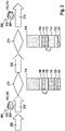
- FIG. 1 shows a flow chart of a production of a control device 100 for a hydraulic system according to an embodiment.
- the control device 100 is connected to an actuator unit 102 for controlling valves of a hydraulic unit.
- the hydraulic system is part of a braking system of a vehicle.
- a driver assistance system, such as ESP, is implemented in the braking system.
- the actuator unit 102 here has electrical coils for solenoid valves of the hydraulic unit.
- the control device 100 and the actuator unit 102 are manufactured in a manufacturing step 104 as a common assembly.
- control unit 100 is programmed with checking and test software 108 in a programming step 106 .
- the checking and testing software 108 is written to a memory 116 of the control unit 100 with a plurality of subprograms 110 , 112 , 114 .
- the checking and testing software 108 only occupies a small portion of the memory 116.
- the programming 106 thus takes only a short time.
- This check and test SW consists of sub-programs 110, 112, 114 for the electronic functions and for checking the hydraulic functions, if necessary a boot manager 114 for activating or deactivating the individual sub-programs 110, 112, 114.
- the sub-programs 110, 112, 114 can be activated individually.
- the electronics test software 110 is activated in step 106 of programming.
- control unit 100 and actuator unit 102 are tested for their intended function in the uninstalled state using electronics testing software 110 . For example, it is checked whether all components are electrically contacted.
- control unit 100 and actuator unit 102 are delivered in a step 120 .
- assembly test software 122 for testing the components of the overall system during assembly in the vehicle is also written to memory 116 as a subroutine in step 106 of programming and is deactivated.
- control software 124 that is not adapted to a vehicle type or is not adapted to a vehicle is also written to memory 116 in step 106 of programming.
- the vehicle-unadapted control software provides a Basic functionality of the brake system ready when the hydraulic system is installed in the vehicle.
- the vehicle-unadapted control software 124 offers interfaces to electronics of the vehicle, as provided by vehicle-adapted control software. With this basic functionality of the brake system, the vehicle can be moved during production without error messages from the vehicle electronics occurring.
- the vehicle-unadapted control software 124 has a low storage requirement.
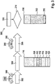
- the hydraulic system 200 consists of a control unit 100 and an actuator unit 102, as shown in 1 are described, and a hydraulic block 202.
- the hydraulic block 202 also includes a hydraulic pump, which is driven by an electric motor 204 of the hydraulic system 200.
- the hydraulic block 202 with the electric motor 204 is manufactured in a manufacturing step 206 .
- control unit 100 and actuator unit 102 are connected to hydraulic block 202 and electric motor 204 .
- a programming or switching step 210 the boot manager 114 is used to disable the electronics test software 110 and enable the full test software 112 . Since the complete test and test software 108 has already been written into the memory 116 during the production of the control unit 100, the programming or switching 210 requires very little time.
- step 210 can be skipped.
- the hydraulic system 200 is tested for its intended function using the complete test software 112 .
- the solenoid valves are actuated and the end positions of the closure parts of the solenoid valves are recorded.
- the hydraulic system 200 can also be connected to a test system and supplied with hydraulic fluid.
- the test system can be used to calibrate the Hydraulic system 200, for example, characteristics of the pump and / or the solenoid valves are recorded.
- the recorded data can be stored in control device 100 .
- the boot manager 114 is used again in a further step 214 of the programming.
- the complete test software 112 is deactivated and the boot manager 114 is activated.
- the hydraulic system 200 is delivered in a step 216 of delivery.
- the installation test software 122 is activated instead of the boot manager 114, via which the intended installation of the hydraulic system in the vehicle can be monitored.
- the boot manager 114 is used to activate the vehicle-unadapted control software 124 .
- the vehicle-unadapted control software 124 externally maps the expected interfaces to the vehicle, as would also be done by vehicle-adapted control software. This avoids error messages during assembly since the vehicle electronics can communicate with the hydraulic system 200 as expected.
- the entire system 200 is checked in the factory for the hydraulic system 200 using the checking and test software 108 already installed in the factory for the control unit ECU 100.
- a bootloader 114 alone is used to switch from the subprogram 110 required in the control unit factory to that in the hydraulic system factory required subprogram 112 switched.
- all test steps in this production process are carried out with a uniform SW 108 software, which does not contain any customer-specific features.
- FIG 3 shows a flow chart of an assembly of a vehicle 300 with a hydraulic system 200 according to an embodiment.
- the hydraulic system 200 essentially corresponds to that in 2 described hydraulic system.
- the actual assembly takes place in a step 302 of installation.
- the hydraulic system 200 in the vehicle becomes 300 placed, secured and connected to the vehicle 300 systems. Together with the brakes and sensors on the wheels, the hydraulic system 200 forms a braking system with an electronic braking system of the vehicle 300 .
- step 304 of testing the systems of vehicle 300 are tested in vehicle 300 .
- the hydraulic system 200 is also checked in the process. If the systems have been checked and they are working as expected, the vehicle 300 is delivered in a step 306 of delivery.
- a method 308 for managing the brake system control software 124 is performed.
- vehicle-adapted control software 312 is downloaded from a server via a wireless interface of vehicle 300 .
- the control unit of the brake system is flashed onto the vehicle-adapted control software 312 .
- the memory 116 of the control unit is at least partially erased and overwritten with the control software 312 adapted to the vehicle.
- the checking and test software subprograms 108 to 112 are also deleted in the process.
- the management method 308 can already be carried out as soon as the hydraulic system 200 is electrically contacted. In one embodiment, the method 308 of managing is performed subsequent to the step 304 of checking.
- the method 308 for managing is performed again when a newer version of the vehicle-adapted control software 312 is available. This involves accessing the wireless data interface again and downloading the newer version. Step 314 of flashing is then carried out again and the control unit is flashed to the new version of the control software 312 adapted to the vehicle.
- the flashing 314 can be carried out when the vehicle 300 is parked. Flashing 314 can also be performed while the vehicle is in use. Flashing is then carried out when no control intervention of the brake system is required, for example when vehicle 300 is stationary.
- a diagnostic program 316 is downloaded in addition to the control software 312 and written to memory 116 in step 314 of flashing. After flashing 314, diagnostic program 316 is executed. If an error is detected, the method 308 can be performed again.
- the vehicle manufacturer installs the system 200, checks its vehicle assembly using diagnostics and end-of-line tests, and delivers the vehicle 300. Before the vehicle 300 is delivered to the buyer, a flashing process 314 takes place, during which the final software 312 is installed. The period between the production of the system 200 and the installation in the vehicle 300 or the final commissioning can be used to further develop the software 312, which leads to savings in lead times.
- a software update can be carried out on the systems 200 delivered in the field using FOTA technology (Flashing over the Air).
- the system 200 is delivered without a functioning overall software, the product 200 only becomes fully functional through the first FOTA process 314.
- This allows the factory processes in the manufacture of the system 200 to be run through with a vehicle-independent, uniform and freely changeable test software 108.
- this includes the ability to be overwritten by FOTA and meets the most up-to-date security requirements required at this point in time.
- a rudimentary functionality 124 can be provided, which ideally can be uniform across vehicles.
- the limited function includes at least a backup EBD, a speed sensor processing and an output of the speedometer signal.
- the product 200 is not fully functional as long as no FOTA process 314 has taken place.
- the hydraulic system 200 When the hydraulic system 200 is manufactured, only a portion of the memory 116 needs to be programmed. The overall system 200 can be produced without direct assignment to a specific vehicle, the final Determination of the target vehicle only takes place after assembly 302 in vehicle 300. A vehicle manufacturer can use absolutely the same brake system 200 in different vehicles 300. The required differences in the functionality are only installed when the control software 321 is flashed 314 as long as the hardware is the same. The hydraulic system 200 can be updated.
- the approach presented here is based on a braking system with ESP. It can also be used with other systems in the vehicle 300 such as engine control, navigation systems, instruments.
Landscapes
- Engineering & Computer Science (AREA)
- Software Systems (AREA)
- General Engineering & Computer Science (AREA)
- Theoretical Computer Science (AREA)
- Transportation (AREA)
- Mechanical Engineering (AREA)
- Physics & Mathematics (AREA)
- General Physics & Mathematics (AREA)
- Computer Security & Cryptography (AREA)
- Regulating Braking Force (AREA)
- Valves And Accessory Devices For Braking Systems (AREA)
- Stored Programmes (AREA)
Description
- Verfahren zum Verwalten einer Steuerungssoftware eines Bremssystems eines Fahrzeugs, Hydrauliksystem für ein Bremssystem eines Fahrzeugs und Verfahren zum Herstellen desselben.
- Die Erfindung betrifft ein Verfahren zum Verwalten einer Steuerungssoftware eines Bremssystems eines Fahrzeugs, ein Hydrauliksystem für ein Bremssystem für ein Fahrzeug und ein Verfahren zum Herstellen eines Hydrauliksystems für ein Bremssystem.
- Bei einem Bremssystem, wie einem ESP-System wird während der Produktion des Systems eine auf ein spezifisches Fahrzeugmodell abgestimmte Steuerungssoftware aufgespielt. Dadurch ist die Steuerungssoftware auf einem Stand, der zur Zeit der Produktion aktuell ist.
- In der
US 2009/0119657 A1 wird ein Verfahren zum Upgraden von Software beschrieben. In derDE 10 2015 115 855 A1 werden ein System und Verfahren zur Verteilung und/oder Aktualisierung von Software in vernetzten Steuereinrichtungen eines Fahrzeugs beschrieben. In derDE 40 28 561 A1 werden ein Verfahren und eine Vorrichtung zur statischen Prüfung der einzelnen Komponenten eines Antiblockierschutz- und/oder Antriebsschlupfregelungssystems in einem Kraftfahrzeug beschrieben. - Vor diesem Hintergrund werden mit dem hier vorgestellten Ansatz ein Verfahren zum Verwalten einer Steuerungssoftware eines Bremssystems eines Fahrzeugs, ein Hydrauliksystem für ein Bremssystem für ein Fahrzeug, sowie schließlich ein Verfahren zum Herstellen eines Hydrauliksystems für ein Bremssystem gemäß den unabhängigen Ansprüchen vorgestellt. Vorteilhafte Weiterbildungen und Verbesserungen des hier vorgestellten Ansatzes sind in den abhängigen Ansprüchen beschrieben.
- Ausführungsformen der vorliegenden Erfindung können in vorteilhafter Weise ermöglichen, eine Steuerungssoftware für ein Bremssystem, insbesondere für ein ESP zu verbessern, bis ein Fahrzeug endmontiert wird. Dadurch können die Parameter der Steuerungssoftware genauer festgelegt werden. Beispielsweise kann so auf Veränderungen am Fahrzeugtyp im Laufe eines Produktionszeitraums reagiert werden. Weiterhin kann eine Lagerhaltung vereinfacht werden, da ein Hydrauliksystemtyp gemäß dem hier vorgestellten Ansatz in unterschiedliche Fahrzeugtypen eingebaut werden kann.
- Es wird ein Verfahren gemäß Anspruch 1 zum Verwalten einer Steuerungssoftware eines Bremssystems eines Fahrzeugs vorgestellt.
- Weiterhin wird ein Hydrauliksystem gemäß Anspruch 7 für ein Bremssystem vorgestellt
- Ferner wird ein Verfahren gemäß Anspruch 8 zum Herstellen eines Hydrauliksystems für ein Bremssystem eines Fahrzeugs vorgestellt.
- Ideen zu Ausführungsformen der vorliegenden Erfindung können unter anderem als auf den nachfolgend beschriebenen Gedanken und Erkenntnissen beruhend angesehen werden.
- Zum Beeinflussen der Fahrstabilität über ein Bremssystem, insbesondere ein ESP-System stehen bei allen Fahrzeugtypen die Bremsen zur Verfügung. Die Bremsen werden hydraulisch angesteuert. Solange ein Fahrzeug vier Räder aufweist sind die Hydrauliksysteme verschiedener Fahrzeugtypen mechanisch und elektrisch sehr ähnlich. Die Hydrauliksysteme weisen im Wesentlichen für jede Bremse eine Gruppe einzeln ansteuerbares Hydraulikventile auf. Die Hydraulikventile werden in unterschiedlichen Fahrzeugtypen über unterschiedliche Steuerungssoftware fahrzeugspezifisch angesteuert. In der fahrzeugangepassten Steuerungssoftware sind erfindungsgemäß fahrzeugspezifische Geometrieverhältnisse, Masseverteilungen und/oder Leistungsdaten berücksichtigt.
- Die Steuerungssoftware ist in einem nicht volatilen Speicher eines Steuergeräts des Bremssystems gespeichert. Der Speicher kann beispielsweise ein ROM PROM oder insbesondere ein EPROM sein. Dieser Speicher kann während der Produktion des Steuergeräts oder während der Produktion des Hydrauliksystems initial beschrieben werden. Bei dem hier vorgestellten Ansatz wird bei der Produktion eine allgemeine Steuerungssoftware eingespeichert. Die allgemeine Steuerungssoftware ermöglicht beispielsweise einen Systemtest des Bremssystems bei der Produktion des Fahrzeugs.
- Wenn das Fahrzeug zusammengebaut wird, werden seine Komponenten zusammengefügt und angeschlossen. Sobald ein Hydrauliksystem eingebaut ist, steht endgültig fest, in welchem Fahrzeugtyp es verbaut ist. Nach dem Einbau können elektrische Komponenten bereits mit elektrischer Energie versorgt werden. So können die Komponenten ab diesem Zeitpunkt eine Initialisierungssequenz durchlaufen, während das Fahrzeug weiter montiert wird. Bevor das Fahrzeug an den Kunden übergeben wird, kann das hier vorgestellte Verfahren ausgeführt werden. Unter Flashen kann ein Überschreiben von in einem Festwertspeicher (ROM, PROM, EPROM) des Steuergeräts gespeicherten Daten verstanden werden. Dabei kann die allgemeine Steuerungssoftware gelöscht werden und mit einer zu dem Zeitpunkt aktuellen Version der endgültigen Steuerungssoftware für diesen Fahrzeugtyp überschrieben werden. Der Festwertspeicher kann zuvor auch nur partiell beschrieben sein.
- Das Verfahren kann einen Schritt des Startens aufweisen, in dem ein vorinstallierter Bootmanager des Bremssystems gestartet wird, wobei der Bootmanager die Schritte des Herunterladens und des Flashens steuert und absichert. Der Bootmanager kann das Flashen auslösen, indem die vorher im Steuergerät gespeicherte Steuerungssoftware gelöscht wird. Anschließend kann der geleerte Speicher des Steuergeräts mit der fahrzeugangepassten Steuerungssoftware beschrieben werden.
- Im Schritt des Flashens kann eine vorinstallierte fahrzeugunangepasste Steuerungssoftware überschrieben werden. Durch das Flashen kann das Bremssystem seinen vollen Funktionsumfang erhalten.
- Das Herunterladen kann auf einem Zentralsystem des Fahrzeugs über eine Schnittstelle des Zentralsystems zu dem Bremssystem ausgeführt werden. Beispielsweise kann ein Zentralsystem ein Navigationssystem oder ein Infotainmentsystem des Fahrzeugs sein. Das Zentralsystem kann eine mobile Datenverbindung zu dem Server aufbauen. Das Zentralsystem kann auch für die Sicherheit der Datenverbindung sorgen, beispielsweise durch einen Virenscan und/oder eine Firewall.
- Der Schritt des Flashens kann ausgeführt werden, wenn das Fahrzeug abgeschaltet ist. Das Flashen kann ausgeführt werden, wenn das Fahrzeug steht. Dadurch kann sichergestellt werden, dass das Bremssystem immer funktionsbereit ist.
- Die Schritte des Herunterladens und Flashens können erneut ausgeführt werden, wenn eine aktualisierte fahrzeugangepasste Steuerungssoftware verfügbar ist. Dabei kann im Schritt des Herunterladens die aktualisierte fahrzeugangepasste Steuerungssoftware heruntergeladen werden. Im Schritt des Flashens kann das Steuergerät auf die aktualisierte Steuerungssoftware geflasht werden. Durch ein nachträgliches Aktualisieren der Steuerungssoftware können Verbesserungen der Steuerungssoftware ohne einen Werkstattbesuch erreicht werden.
- Das Verfahren zum Herstellen kann einen Schritt des Deaktivierens aufweisen, in dem die Prüf- und Testsoftware für das Steuergerät und die Prüf- und Testsoftware für das Hydrauliksystem deaktiviert werden. Die durch die Prüf- und Testsoftware angesteuerten Sequenzen können im verbauten Steuergerät nicht mehr ausgeführt werden. Daher ist die Prüf- und Testsoftware nicht mehr erforderlich. Die Prüf- und Testsoftware kann auch gelöscht werden, um Speicherplatz im Steuergerät freizumachen.
- Vor dem Schritt des Prüfens der mechanischen Funktion des Hydrauliksystems kann unter Verwendung des Bootmanagers von der Prüf- und Testsoftware für das Steuergerät auf die Prüf- und Testsoftware für das Hydrauliksystem umgeschaltet werden. Die durch die Prüf- und Testsoftware für das Steuergerät angesteuerte Sequenz kann im zusammengebauten Hydrauliksystem nicht mehr ausgeführt werden. Daher sind die Prüf- und Testsoftware und der hierzu erforderliche Bootmanager nicht mehr erforderlich.
- Es wird darauf hingewiesen, dass einige der möglichen Merkmale und Vorteile der Erfindung hierin mit Bezug auf unterschiedliche Ausführungsformen als Verfahren zum Verwalten, als Steuergerät und als Verfahren zum Herstellen beschrieben sind. Ein Fachmann erkennt, dass die Merkmale in geeigneter Weise kombiniert, angepasst oder ausgetauscht werden können, um zu weiteren Ausführungsformen der Erfindung zu gelangen.
- Nachfolgend werden Ausführungsformen der Erfindung unter Bezugnahme auf die beigefügten Zeichnungen beschrieben, wobei weder die Zeichnungen noch die Beschreibung als die Erfindung einschränkend auszulegen sind.
-
Fig. 1 zeigt ein Ablaufdiagramm einer Produktion eines Steuergeräts für ein Hydrauliksystem gemäß einem Ausführungsbeispiel; -
Fig. 2 zeigt ein Ablaufdiagramm einer Produktion eines Hydrauliksystems gemäß einem Ausführungsbeispiel; und -
Fig. 3 zeigt ein Ablaufdiagramm einer Montage eines Fahrzeugs mit einem Hydrauliksystem gemäß einem Ausführungsbeispiel. - Die Figuren sind lediglich schematisch und nicht maßstabsgetreu. Gleiche Bezugszeichen bezeichnen in den Figuren gleiche oder gleichwirkende Merkmale.
-
Fig. 1 zeigt ein Ablaufdiagramm einer Produktion eines Steuergeräts 100 für ein Hydrauliksystem gemäß einem Ausführungsbeispiel. Das Steuergerät 100 ist dabei mit einer Aktoreinheit 102 zum Ansteuern von Ventilen einer Hydraulikeinheit verbunden. Das Hydrauliksystem ist Bestandteil eines Bremssystems eines Fahrzeuges. Im Bremssystem ist ein Fahrerassistenzsystem, wie beispielsweise ESP umgesetzt. Die Aktoreinheit 102 weist hier elektrische Spulen für Magnetventile der Hydraulikeinheit auf. Das Steuergerät 100 und die Aktoreinheit 102 werden in einem Schritt 104 des Fertigens als gemeinsame Baugruppe gefertigt. - Während der Fertigung 104 wird das Steuergerät 100 in einem Schritt 106 des Programmierens mit einer Prüf- und Testsoftware 108 programmiert. Die Prüf- und Testsoftware 108 wird mit mehreren Unterprogrammen 110, 112, 114 in einen Speicher 116 des Steuergeräts 100 geschrieben. Die Prüf- und Testsoftware 108 belegt dabei nur einen geringen Anteil des Speichers 116. Das Programmieren 106 dauert so nur kurz. Diese Prüf- und Test-SW besteht aus Unterprogrammen 110, 112, 114 für die elektronischen Funktionen sowie zum Überprüfen der hydraulischen Funktionen, ggfs. eines Bootmanagers 114 zum Aktivieren beziehungsweise Deaktivieren der einzelnen Unterprogramme 110, 112, 114. Die Unterprogramme 110, 112, 114 sind dabei einzeln aktivierbar. Für die Produktion des Steuergeräts 100 wird im Schritt 106 des Programmierens die Elektronikprüfsoftware 110 aktiviert.
- In einem nachfolgenden Schritt 118 des Prüfens werden die einzelnen Komponenten des Steuergeräts 100 und der Aktoreinheit 102 im unverbauten Zustand unter Verwendung der Elektronikprüfsoftware 110 auf ihre bestimmungsgemäße Funktion geprüft. Beispielsweise wird überprüft, ob alle Komponenten elektrisch kontaktiert sind.
- Wenn bei der Prüfung 118 die bestimmungsgemäße Funktion erkannt worden ist, werden das Steuergerät 100 und die Aktoreinheit 102 in einem Schritt 120 ausgeliefert.
- In einem Ausführungsbeispiel wird im Schritt 106 des Programmierens als Unterprogramm ferner eine Montagetestsoftware 122 zum Überprüfen der Komponenten des Gesamtsystems bei der Montage in das Fahrzeug in den Speicher 116 geschrieben und deaktiviert.
- In einem Ausführungsbeispiel wird im Schritt 106 des Programmierens ferner eine nicht an einen Fahrzeugtyp angepasste beziehungsweise fahrzeugunangepasste Steuerungssoftware 124 in den Speicher 116 geschrieben. Die fahrzeugunangepasste Steuerungssoftware stellt eine Basisfunktionalität des Bremssystems bereit, wenn das Hydrauliksystem im Fahrzeug verbaut ist. Beispielsweise bietet die fahrzeugunangepasste Steuerungssoftware 124 Schnittstellen zu einer Elektronik des Fahrzeugs, wie sie durch eine fahrzeugangepasste Steuerungssoftware bereitgestellt werden. Durch diese Basisfunktionalität des Bremssystems kann das Fahrzeug bei der Produktion bewegt werden, ohne dass es zu Fehlermeldungen der Fahrzeugelektronik kommt. Die fahrzeugunangepasste Steuerungssoftware 124 weist einen geringen Speicherbedarf auf.
-
Fig. 2 zeigt ein Ablaufdiagramm einer Produktion eines Hydrauliksystems 200 gemäß einem Ausführungsbeispiel. Das Hydrauliksystem 200 besteht dabei aus einem Steuergerät 100 und einer Aktoreinheit 102, wie sie inFig. 1 beschrieben sind, sowie einem Hydraulikblock 202. Der Hydraulikblock 202 umfasst dabei auch eine Hydraulikpumpe, die von einem Elektromotor 204 des Hydrauliksystems 200 angetrieben wird. - Der Hydraulikblock 202 mit dem Elektromotor 204 wird in einem Schritt 206 des Fertigens gefertigt. In einem Schritt 208 des Montierens werden das Steuergerät 100 und die Aktoreinheit 102 mit dem Hydraulikblock 202 und dem Elektromotor 204 verbunden.
- In einem Schritt 210 des Programmierens oder Umschaltens wird der Bootmanager 114 verwendet, um die Elektronikprüfsoftware 110 zu deaktivieren und die Kompletttestsoftware 112 zu aktivieren. Da die komplette Prüf- und Testsoftware 108 bereits während der Produktion des Steuergeräts 100 in den Speicher 116 geschrieben worden ist, benötigt das Programmieren oder Umschalten 210 nur sehr wenig Zeit.
- Das Programmieren kann ebenso bereits bei der Produktion des Steuergeräts 100 vor dem Ausliefern des Steuergeräts 100 mit der Aktoreinheit 102 erfolgt sein. Dann kann der Schritt 210 übersprungen werden.
- In einem nachfolgenden Schritt 212 des Prüfens wird das Hydrauliksystem 200 unter Verwendung der Kompletttestsoftware 112 auf seine bestimmungsgemäße Funktion geprüft. Beispielsweise werden die Magnetventile betätigt und Endlagen der Verschlussteile der Magnetventile aufgezeichnet. Im Schritt 212 des Prüfens kann das Hydrauliksystem 200 auch an ein Prüfsystem angeschlossen und mit Hydraulikfluid versorgt werden. Über das Prüfsystem können zum Kalibrieren des Hydrauliksystems 200 beispielsweise Kennlinien der Pumpe und/oder der Magnetventile aufgezeichnet werden. Die aufgezeichneten Daten können in dem Steuergerät 100 abgespeichert werden.
- Wenn das Hydrauliksystem 200 bestimmungsgemäß funktioniert, wird der Bootmanager 114 in einem weiteren Schritt 214 des Programmierens erneut verwendet. Dabei wird die Kompletttestsoftware 112 deaktiviert und der Bootmanager 114 aktiviert. Nach dem Umprogrammieren 214 wird das Hydrauliksystem 200 in einem Schritt 216 des Auslieferns ausgeliefert.
- In einem Ausführungsbeispiel wird im weiteren Schritt 214 des Programmierens anstatt des Bootmanagers 114 die Montagetestsoftware 122 aktiviert, über die der bestimmungsgemäße Einbau des Hydrauliksystems in das Fahrzeug überwacht werden kann.
- In einem Ausführungsbeispiel wird im weiteren Schritt 214 des Programmierens der Bootmanager 114 verwendet, um die fahrzeugunangepasste Steuerungssoftware 124 zu aktivieren. Die fahrzeugunangepasste Steuerungssoftware 124 bildet nach außen die erwarteten Schnittstellen zum Fahrzeug ab, wie es auch eine fahrzeugangepasste Steuerungssoftware machen würde. Dadurch werden Fehlermeldungen bei der Montage vermieden, da die Fahrzeugelektronik wie erwartet mit dem Hydrauliksystem 200 kommunizieren kann.
- Mit anderen Worten erfolgt im Werk für das Hydrauliksystem 200 eine Überprüfung des Gesamtsystems 200 mithilfe der bereits im Werk für das Steuergerät ECU 100 aufgespielten Prüf- und Testsoftware 108. Alleine mittels eines Bootloaders 114 wird hierbei von dem im Steuergerätewerk benötigten Unterprogramm 110 auf das im Hydrauliksystemwerk benötigten Unterprogramm 112 umgeschaltet. Als Konsequenz erfolgen in diesem Fertigungsablauf alle Prüfschritte mit einer einheitlichen Software SW 108, welche keine kundenspezifischen Merkmale enthält.
-
Fig. 3 zeigt ein Ablaufdiagramm einer Montage eines Fahrzeugs 300 mit einem Hydrauliksystem 200 gemäß einem Ausführungsbeispiel. Das Hydrauliksystem 200 entspricht dabei im Wesentlichen dem inFig. 2 beschriebenen Hydrauliksystem. Die eigentliche Montage findet in einem Schritt 302 des Einbauens statt. Dabei wird das Hydrauliksystem 200 im Fahrzeug 300 angeordnet, befestigt und mit den Systemen des Fahrzeugs 300 verbunden. Zusammen mit den Bremsen und Sensoren an den Rädern bildet das Hydrauliksystem 200 ein Bremssystem mit einem elektronischen Bremssystem des Fahrzeugs 300 aus. - In einem nachfolgenden Schritt 304 des Prüfens werden die Systeme des Fahrzeugs 300 im Fahrzeug 300 geprüft. Dabei wird auch das Hydrauliksystem 200 überprüft. Wenn die Systeme überprüft worden sind und sie wie erwartet funktionieren, wird das Fahrzeug 300 in einem Schritt 306 des Auslieferns ausgeliefert.
- Bevor das Fahrzeug 300 endgültig an seinen Nutzer übergeben wird, wird ein Verfahren 308 zum Verwalten der Steuerungssoftware 124 des Bremssystems ausgeführt. Dabei wird in einem Schritt 310 des Herunterladens eine fahrzeugangepasste Steuerungssoftware 312 über eine drahtlose Schnittstelle des Fahrzeugs 300 von einem Server heruntergeladen. In einem nachfolgenden Schritt 314 des Flashens wird das Steuergerät des Bremssystems auf die fahrzeugangepasste Steuerungssoftware 312 geflasht. Beim Flashen 314 wird der Speicher 116 des Steuergeräts zumindest teilweise gelöscht und mit der fahrzeugangepassten Steuerungssoftware 312 überschrieben. Dabei werden auch die Prüf- und Testsoftware Unterprogramme 108 bis 112 gelöscht.
- Das Verfahren 308 zum Verwalten kann bereits ausgeführt werden, sobald das Hydrauliksystem 200 elektrisch kontaktiert ist. In einem Ausführungsbeispiel wird das Verfahren 308 zum Verwalten anschließend an den Schritt 304 des Prüfens ausgeführt.
- In einem Ausführungsbeispiel wird das Verfahren 308 zum Verwalten erneut ausgeführt, wenn eine neuere Version der fahrzeugangepassten Steuerungssoftware 312 verfügbar ist. Dabei wird erneut über die drahtlose Datenschnittstelle zugegriffen und die neuere Version heruntergeladen. Anschließend wird erneut der Schritt 314 des Flashens ausgeführt und das Steuergerät auf die neue Version der fahrzeugangepassten Steuerungssoftware 312 geflasht. Das Flashen 314 kann dabei ausgeführt werden, wenn das Fahrzeug 300 abgestellt ist. Das Flashen 314 kann auch ausgeführt werden, während das Fahrzeug in Benutzung ist. Dann wird das Flashen ausgeführt, wenn kein Regeleingriff des Bremssystems erforderlich ist, also beispielsweise bei Stillstand des Fahrzeugs 300.
- In einem Ausführungsbeispiel wird im Schritt 310 des Herunterladens ein Diagnoseprogramm 316 zusätzlich zu der Steuerungssoftware 312 heruntergeladen und im Schritt 314 des Flashens mit in den Speicher 116 geschrieben. Nach dem Flashen 314 wird das Diagnoseprogramm 316 ausgeführt. Wenn ein Fehler erkannt wird, kann das Verfahren 308 erneut ausgeführt werden.
- Mit anderen Worten verbaut der Fahrzeughersteller das System 200, prüft mithilfe von Diagnose und Band-Ende Prüfungen seinen Fahrzeugzusammenbau und liefert das Fahrzeug 300 aus. Vor Auslieferung des Fahrzeugs 300 an den Abnehmer erfolgt ein Flashvorgang 314, bei dem die finale Software 312 aufgespielt wird. Der Zeitraum zwischen der Produktion des Systems 200 und dem Verbau im Fahrzeug 300 bzw. der finalen Inbetriebnahme kann zur Weiterentwicklung der Software 312 genutzt werden, was zur Einsparung von Vorlaufzeiten führt.
- Durch den hier vorgestellten Ansatz kann mittels FOTA Technologie (Flashing over the Air) ein Softwareupdate an den im Feld ausgelieferten Systemen 200 durchgeführt werden. Die Auslieferung des Systems 200 erfolgt ohne eine funktionierende Gesamtsoftware, das Produkt 200 wird erst vollständig funktionsfähig durch den ersten FOTA Vorgang 314. Dadurch können die Werksprozesse bei der Herstellung des Systems 200 mit einer fahrzeugunabhängigen, einheitlichen und frei änderbaren Prüf-Software 108 durchlaufen werden. Diese beinhaltet neben den Prüfanteilen 110, 112 die Fähigkeit per FOTA überschrieben zu werden und erfüllt die zu diesem Zeitpunkt erforderlichen und aktuellsten Security Anforderungen.
- Bei Bedarf kann eine rudimentäre Funktionalität 124 bereitgestellt werden, welche idealerweise fahrzeugübergreifend einheitlich ausfallen kann. Die eingeschränkte Funktion umfasst dabei zumindest ein Backup-EBD, eine Drehzahlfühleraufbereitung und eine Ausgabe des Tachosignals. Das Produkt 200 ist solange nicht voll funktionsfähig, wie kein FOTA Vorgang 314 sattgefunden hat.
- Bei der Herstellung des Hydrauliksystems 200 muss nur ein Teilbereich des Speichers 116 programmiert werden. Das Gesamtsystem 200 kann ohne direkte Zuordnung zu einem spezifischen Fahrzeug produziert werden, die finale Festlegung auf das Zielfahrzeug erfolgt erst nach der Montage 302 im Fahrzeug 300. Dabei kann ein Fahrzeughersteller das absolut gleiche Bremssystem 200 in verschiedenen Fahrzeugen 300 einsetzen. Die erforderlichen Unterschiede in der Funktionalität werden erst beim Flashen 314 der Steuerungssoftware 321 aufgespielt, solange die Hardware gleich ist. Das Hydrauliksystem 200 ist updatefähig.
- Der hier vorgestellte Ansatz ist an einem Bremssystem mit ESP beschrieben. Er kann auch bei anderen Systemen im Fahrzeug 300, wie Motorsteuerung, Navigationssystemen, Instrumenten verwendet werden.
- Abschließend ist darauf hinzuweisen, dass Begriffe wie "aufweisend", "umfassend", etc. keine anderen Elemente oder Schritte ausschließen und Begriffe wie "eine" oder "ein" keine Vielzahl ausschließen. Bezugszeichen in den Ansprüchen sind nicht als Einschränkung anzusehen.
Claims (10)
- Verfahren (308) zum Verwalten einer Steuerungssoftware (124, 312) eines Bremssystems eines Fahrzeugs (300), dadurch gekennzeichnet, dass die Steuerungssoftware anfänglich als fahrzeugunangepasste Steuerungssoftware in ein Steuergerät vorinstalliert ist und dass in einem Schritt (310) des Herunterladens eine fahrzeugangepasste Steuerungssoftware (312) über eine drahtlose Schnittstelle des Fahrzeugs (300) von einem Server heruntergeladen wird, und vor einem Ausliefern des Fahrzeugs in einem Schritt (314) des Flashens das Steuergerät (100) des Bremssystems auf die fahrzeugangepasste Steuerungssoftware (312) geflasht wird,
wobei die fahrzeugangepasste Steuerungssoftware (312) hinsichtlich Parametern der Steuerungssoftware (312) genauer festgelegt ist, wobei die Parameter fahrzeugspezifische Geometrieverhältnisse, Masseverteilungen und/oder Leistungsdaten umfassen. - Verfahren (308) gemäß Anspruch 1, mit einem Schritt des Startens, in dem ein vorinstallierter Bootmanager (314) des Bremssystems (200) gestartet wird, wobei der Bootmanager (314) die Schritte (310, 314) des Herunterladens und des Flashens ansteuert.
- Verfahren (308) gemäß einem der vorhergehenden Ansprüche, bei dem im Schritt (314) des Flashens die vorinstallierte fahrzeugunangepasste Steuerungssoftware (124) überschrieben wird.
- Verfahren (308) gemäß einem der vorhergehenden Ansprüche, bei dem der Schritt (310) des Herunterladens auf einem Zentralsystem des Fahrzeugs (300) über eine Schnittstelle des Zentralsystems zu dem Bremssystem ausgeführt wird.
- Verfahren (308) gemäß einem der vorhergehenden Ansprüche, bei dem der Schritt (314) des Flashens ausgeführt wird, wenn das Fahrzeug (300) abgeschaltet ist.
- Verfahren (308) gemäß einem der vorhergehenden Ansprüche, bei dem die Schritte (310, 314) des Herunterladens und Flashens erneut ausgeführt werden, wenn eine aktualisierte fahrzeugangepasste Steuerungssoftware (312) verfügbar ist, wobei im Schritt (310) des Herunterladens die aktualisierte fahrzeugangepasste Steuerungssoftware (312) heruntergeladen wird, und im Schritt (314) des Flashens das Steuergerät (100) auf die aktualisierte Steuerungssoftware (312) geflasht wird.
- Hydrauliksystem (200) für ein Bremssystem eines Fahrzeugs (300), wobei ein Steuergerät (100) des Hydrauliksystems (200) dazu ausgebildet ist, das Verfahren (308) gemäß einem der vorhergehenden Ansprüche in entsprechenden Einrichtungen auszuführen, umzusetzen und/oder anzusteuern.
- Verfahren zum Herstellen eines Hydrauliksystems (200) für ein Bremssystem eines Fahrzeugs (300), wobei das Verfahren die folgenden Schritte aufweist:Fertigen (104, 206) eines flashbaren Steuergeräts (100) des Hydrauliksystems (200) und einer Hydraulikeinheit (202) des Hydrauliksystems (200);Programmieren (106) des Steuergeräts (100) mit einer Prüf- und Testsoftware (110) für das Steuergerät (100), einer Prüf- und Testsoftware (112) für das Hydrauliksystem (200) und einer Prüf- und Testsoftware (122) für Aktoren des Bremssystems, sowie einer fahrzeugunangepassten Steuerungssoftware (124) für das Bremssystem und einem Bootmanager (114) zum Flashen des Steuergeräts (100) mittels eines Verfahrens zum Verwalten der Steuerungssoftware (124) gemäß einem der Ansprüche 1 bis 7 vor einem Ausliefern des Fahrzeugs;Prüfen (118) einer elektrischen Funktion des Steuergeräts (100) unter Verwendung der Prüf- und Testsoftware (110) für das Steuergerät (100);Zusammenbauen (208) des Steuergeräts (100) und der Hydraulikeinheit (202) zu dem Hydrauliksystem (200); undPrüfen (210) einer mechanischen Funktion des Hydrauliksystems (200) unter Verwendung der Prüf- und Testsoftware (112) für das Hydrauliksystem (200).
- Verfahren gemäß Anspruch 8, mit einem Schritt (214) des Deaktivierens, in dem die Prüf- und Testsoftware (110) für das Steuergerät (100) und die Prüf- und Testsoftware (112) für das Hydrauliksystem (200) deaktiviert werden.
- Verfahren gemäß einem der Ansprüche 8 bis 9, bei dem vor dem Schritt (210) des Prüfens der mechanischen Funktion des Hydrauliksystems (200) unter Verwendung des Bootmanagers (114) von der Prüf- und Testsoftware (210) für das Steuergerät (100) auf die Prüf- und Testsoftware (212) für das Hydrauliksystem (200) umgeschaltet wird.
Applications Claiming Priority (2)
| Application Number | Priority Date | Filing Date | Title |
|---|---|---|---|
| DE102017209104.5A DE102017209104A1 (de) | 2017-05-31 | 2017-05-31 | Verfahren zum Verwalten einer Steuerungssoftware eines Bremssystems eines Fahrzeugs, Hydrauliksystem für ein Bremssystem eines Fahrzeugs und Verfahren zum Herstellen desselben |
| PCT/EP2018/057355 WO2018219518A1 (de) | 2017-05-31 | 2018-03-22 | Verfahren zum verwalten einer steuerungssoftware eines bremssystems eines fahrzeugs, hydrauliksystem für ein bremssystem eines fahrzeugs und verfahren zum herstellen desselben |
Publications (2)
| Publication Number | Publication Date |
|---|---|
| EP3631619A1 EP3631619A1 (de) | 2020-04-08 |
| EP3631619B1 true EP3631619B1 (de) | 2022-07-20 |
Family
ID=61800512
Family Applications (1)
| Application Number | Title | Priority Date | Filing Date |
|---|---|---|---|
| EP18713625.4A Active EP3631619B1 (de) | 2017-05-31 | 2018-03-22 | Verfahren zum verwalten einer steuerungssoftware eines bremssystems eines fahrzeugs, hydrauliksystem für ein bremssystem eines fahrzeugs und verfahren zum herstellen desselben |
Country Status (6)
| Country | Link |
|---|---|
| US (1) | US11708059B2 (de) |
| EP (1) | EP3631619B1 (de) |
| JP (1) | JP6963634B2 (de) |
| CN (1) | CN110651249B (de) |
| DE (1) | DE102017209104A1 (de) |
| WO (1) | WO2018219518A1 (de) |
Families Citing this family (2)
| Publication number | Priority date | Publication date | Assignee | Title |
|---|---|---|---|---|
| DE102022205985A1 (de) | 2022-06-14 | 2023-12-14 | Robert Bosch Gesellschaft mit beschränkter Haftung | Verfahren zum Testen einer elektronischen Einheit |
| DE102022117149A1 (de) | 2022-07-11 | 2024-01-11 | Audi Aktiengesellschaft | Verfahren zum Betrieb eines Steuergeräts eines Kraftfahrzeugs für einen Produktionsvorgang des Kraftfahrzeugs und Steuergerät |
Family Cites Families (22)
| Publication number | Priority date | Publication date | Assignee | Title |
|---|---|---|---|---|
| DE4028561A1 (de) * | 1990-09-08 | 1992-03-12 | Iveco Magirus | Verfahren und vorrichtung zur statischen pruefung der einzelnen komponenten eines antiblockierschutz- und/oder antriebsschlupfregelungssystems in einem kraftfahrzeug |
| JP3578845B2 (ja) * | 1995-10-25 | 2004-10-20 | 株式会社ケーヒン | 車両用コンピュータ搭載製品の検査方法および装置 |
| US6256572B1 (en) * | 1999-03-30 | 2001-07-03 | Kelsey-Hayes Company | Remote programming of an ABS electronic control module |
| JP2003108383A (ja) * | 2001-09-28 | 2003-04-11 | Suzuki Motor Corp | 車両用電子制御装置 |
| US7155324B2 (en) * | 2003-06-10 | 2006-12-26 | General Motors Corporation | Apparatus and method for programming motor vehicle electronic control units |
| JP2005157637A (ja) * | 2003-11-25 | 2005-06-16 | Toyota Motor Corp | プログラム書き込みシステムおよび方法 |
| JP2005202594A (ja) * | 2004-01-14 | 2005-07-28 | Toyota Motor Corp | 電子制御装置へのデータ書込みシステムおよび書込み方法 |
| DE102005008851A1 (de) | 2004-04-29 | 2005-12-01 | Continental Teves Ag & Co. Ohg | Verfahren zum Entlüften einer elektronischen Fahrzeugbremsanlage |
| JP4234062B2 (ja) | 2004-06-08 | 2009-03-04 | 富士通テン株式会社 | ソフトウェア管理装置 |
| JP4127310B2 (ja) | 2006-12-27 | 2008-07-30 | トヨタ自動車株式会社 | 車両の制御装置、制御方法、その方法を実現するプログラムおよびそのプログラムを記録した記録媒体 |
| US20090119657A1 (en) * | 2007-10-24 | 2009-05-07 | Link Ii Charles M | Methods and systems for software upgrades |
| JP2009120364A (ja) | 2007-11-16 | 2009-06-04 | Kyocera Mita Corp | 給紙装置及びこれを搭載した画像形成装置 |
| US20090300595A1 (en) * | 2008-05-30 | 2009-12-03 | Ise Corporation | System and Method for Remotely Updating Control Software in a Vehicle With an Electric Drive System |
| KR101701125B1 (ko) | 2009-06-18 | 2017-02-01 | 콘티넨탈 테베스 아게 운트 코. 오하게 | 유압 작동식 서비스 제동 시스템 및 전자기계 작동식 제동 시스템을 구비한 모터 차량 제동 시스템 |
| KR101498721B1 (ko) * | 2010-05-17 | 2015-03-04 | 주식회사 만도 | 소프트웨어 지원 장치 및 그 지원방법 |
| WO2012043167A1 (ja) | 2010-09-27 | 2012-04-05 | 日本電気株式会社 | 情報処理システム、車両のチェック方法、及び、車両のチェックプログラム |
| US8813061B2 (en) * | 2012-10-17 | 2014-08-19 | Movimento Group | Module updating device |
| WO2014088567A1 (en) | 2012-12-05 | 2014-06-12 | Bendix Commercial Vehicle Systems Llc | Methods and apparatus for updating software components in coordination with operational modes of a motor vehicle |
| DE102013226841A1 (de) | 2013-12-20 | 2015-06-25 | Robert Bosch Gmbh | Verfahren zum Betreiben eines Bremssystems, Bremssystem |
| US9430220B2 (en) * | 2014-07-22 | 2016-08-30 | GM Global Technology Operations LLC | Method, medium, and apparatus for re-programming flash memory of a computing device |
| US10042635B2 (en) | 2015-06-16 | 2018-08-07 | Lear Corporation | Method for wireless remote updating vehicle software |
| DE102015115855A1 (de) * | 2015-09-21 | 2017-03-23 | Knorr-Bremse Systeme für Nutzfahrzeuge GmbH | System und Verfahren zur Verteilung und/oder Aktualisierung von Software in vernetzten Steuereinrichtungen eines Fahrzeugs |
-
2017
- 2017-05-31 DE DE102017209104.5A patent/DE102017209104A1/de not_active Withdrawn
-
2018
- 2018-03-22 CN CN201880036060.5A patent/CN110651249B/zh active Active
- 2018-03-22 WO PCT/EP2018/057355 patent/WO2018219518A1/de not_active Ceased
- 2018-03-22 JP JP2019562642A patent/JP6963634B2/ja active Active
- 2018-03-22 EP EP18713625.4A patent/EP3631619B1/de active Active
- 2018-03-22 US US16/611,082 patent/US11708059B2/en active Active
Also Published As
| Publication number | Publication date |
|---|---|
| US20200164849A1 (en) | 2020-05-28 |
| WO2018219518A1 (de) | 2018-12-06 |
| CN110651249B (zh) | 2023-03-21 |
| US11708059B2 (en) | 2023-07-25 |
| DE102017209104A1 (de) | 2018-12-06 |
| JP6963634B2 (ja) | 2021-11-10 |
| JP2020520023A (ja) | 2020-07-02 |
| CN110651249A (zh) | 2020-01-03 |
| EP3631619A1 (de) | 2020-04-08 |
Similar Documents
| Publication | Publication Date | Title |
|---|---|---|
| EP2425333B1 (de) | Verfahren zur aktualisierung von softwarekomponenten | |
| WO2017108407A1 (de) | Verfahren zur modifikation safety- und/oder security-relevanter steuergeräte in einem kraftfahrzeug, und eine diesbezügliche vorrichtung | |
| EP3631619B1 (de) | Verfahren zum verwalten einer steuerungssoftware eines bremssystems eines fahrzeugs, hydrauliksystem für ein bremssystem eines fahrzeugs und verfahren zum herstellen desselben | |
| KR20190072009A (ko) | 자동차 진단 시스템을 이용한 전자제어유닛 프로그래밍 방법 | |
| EP1874587A1 (de) | Konfigurationssystem eines fahrzeugs und verfahren zur konfiguration mindestens einer steuereinheit des konfigurationssystems | |
| EP1139217B1 (de) | Verfahren zur Abspeicherung von Daten | |
| DE102017208986A1 (de) | Verfahren zum Testen eines geplanten Softwareupdates für ein Fahrzeug | |
| DE102016201769A1 (de) | Verfahren zum Aktualisieren von Software eines Steuergerätes, vorzugsweise für ein Kraftfahrzeug | |
| WO2017125182A1 (de) | Verfahren zum aktualisieren von software eines steuergerätes, vorzugsweise für ein kraftfahrzeug | |
| EP3743815B1 (de) | Vorrichtung und verfahren zum registrieren und überwachen autonomer fahrzeuge | |
| DE102022128804B4 (de) | Verfahren und System zum Aktualisieren einer Betriebssoftware von Teilkomponenten eines Kraftfahrzeugs | |
| WO2024061750A1 (de) | Verfahren für die fahrzeugübergreifende nutzung eines benutzerprofils, steuerungssystem und computerprogrammprodukt | |
| DE102021203435A1 (de) | Verfahren zum Aktualisieren eines Betriebsprogramms zum Betrieb und/oder zur Ansteuerung einer Fahrzeugkomponente eines Fahrzeugs, insbesondere eines Lenksystems des Fahrzeugs | |
| DE102009047974B4 (de) | Verfahren zur Programmierung eines Steuergeräts | |
| WO2025078235A1 (de) | Verfahren zum durchführen eines updates eines steuergeräts in einem fahrzeug | |
| DE102023208799B3 (de) | Verfahren zum Betreiben einer Kommunikationsschnittstelle für eine Fahrzeugentwicklungs-Prüfplatzanlage zum Datenaustausch in Bezug auf ein für ein zu entwickelndes Fahrzeug zu testendes Software-Produkt, Kommunikationsschnittstelle und Fahrzeugentwicklungs-Prüfplatzanlage | |
| DE102018128894A1 (de) | Verfahren, System sowie Computerprogramm zum Bereitstellen einer Information zum Betreiben eines Fahrzeugs, insbesondere mittels einer digitalen Karte | |
| WO2017182210A1 (de) | Verfahren zur programmierung von steuergeräten eines kraftfahrzeugs | |
| DE102022209957A1 (de) | Verfahren für die Steuerung mehrerer Funktionen an einem Fahrzeug über ein zumindest teilweise in einer Steuereinheit implementiertes Steuerungsprogramm einer elektronischen Steuereinrichtung, Steuerungssystem und Computerprogrammprodukt | |
| DE102022209954A1 (de) | Verfahren zur Implementierung eines Steuerungsprogramms in einer elektronischen Steuereinrichtung eines Fahrzeugs, Steuerungssystem und Computerprogrammprodukt | |
| DE102024134175A1 (de) | Verteiltes Netzwerk mit robuster Fehlerindikationseindämmung und Verfahren zur Softwarerevisionssteuerung | |
| DE202025102257U1 (de) | Programmiervorrichtung zum Umsetzen eines Programmierverfahrens von Fahrzeugluftreifen-Drucksensoren | |
| WO2025247540A1 (de) | Aktualisierungssystem, verfahren zum ausrollen von drahtlosaktualisierungen, computerprogrammprodukt und computerlesbares speichermedium | |
| EP2953810B1 (de) | Erkennen von möglichkeiten zur verbesserung der bedienung eines fahrzeugs | |
| DE102015204625A1 (de) | Steuergerät |
Legal Events
| Date | Code | Title | Description |
|---|---|---|---|
| STAA | Information on the status of an ep patent application or granted ep patent |
Free format text: STATUS: UNKNOWN |
|
| STAA | Information on the status of an ep patent application or granted ep patent |
Free format text: STATUS: THE INTERNATIONAL PUBLICATION HAS BEEN MADE |
|
| PUAI | Public reference made under article 153(3) epc to a published international application that has entered the european phase |
Free format text: ORIGINAL CODE: 0009012 |
|
| STAA | Information on the status of an ep patent application or granted ep patent |
Free format text: STATUS: REQUEST FOR EXAMINATION WAS MADE |
|
| 17P | Request for examination filed |
Effective date: 20200102 |
|
| AK | Designated contracting states |
Kind code of ref document: A1 Designated state(s): AL AT BE BG CH CY CZ DE DK EE ES FI FR GB GR HR HU IE IS IT LI LT LU LV MC MK MT NL NO PL PT RO RS SE SI SK SM TR |
|
| AX | Request for extension of the european patent |
Extension state: BA ME |
|
| RAP1 | Party data changed (applicant data changed or rights of an application transferred) |
Owner name: ROBERT BOSCH GMBH |
|
| DAV | Request for validation of the european patent (deleted) | ||
| DAX | Request for extension of the european patent (deleted) | ||
| STAA | Information on the status of an ep patent application or granted ep patent |
Free format text: STATUS: EXAMINATION IS IN PROGRESS |
|
| 17Q | First examination report despatched |
Effective date: 20201215 |
|
| GRAP | Despatch of communication of intention to grant a patent |
Free format text: ORIGINAL CODE: EPIDOSNIGR1 |
|
| STAA | Information on the status of an ep patent application or granted ep patent |
Free format text: STATUS: GRANT OF PATENT IS INTENDED |
|
| INTG | Intention to grant announced |
Effective date: 20220422 |
|
| GRAS | Grant fee paid |
Free format text: ORIGINAL CODE: EPIDOSNIGR3 |
|
| GRAA | (expected) grant |
Free format text: ORIGINAL CODE: 0009210 |
|
| STAA | Information on the status of an ep patent application or granted ep patent |
Free format text: STATUS: THE PATENT HAS BEEN GRANTED |
|
| AK | Designated contracting states |
Kind code of ref document: B1 Designated state(s): AL AT BE BG CH CY CZ DE DK EE ES FI FR GB GR HR HU IE IS IT LI LT LU LV MC MK MT NL NO PL PT RO RS SE SI SK SM TR |
|
| REG | Reference to a national code |
Ref country code: CH Ref legal event code: EP |
|
| REG | Reference to a national code |
Ref country code: DE Ref legal event code: R096 Ref document number: 502018010189 Country of ref document: DE |
|
| REG | Reference to a national code |
Ref country code: AT Ref legal event code: REF Ref document number: 1505962 Country of ref document: AT Kind code of ref document: T Effective date: 20220815 |
|
| REG | Reference to a national code |
Ref country code: IE Ref legal event code: FG4D Free format text: LANGUAGE OF EP DOCUMENT: GERMAN |
|
| REG | Reference to a national code |
Ref country code: LT Ref legal event code: MG9D |
|
| REG | Reference to a national code |
Ref country code: NL Ref legal event code: MP Effective date: 20220720 |
|
| PG25 | Lapsed in a contracting state [announced via postgrant information from national office to epo] |
Ref country code: SE Free format text: LAPSE BECAUSE OF FAILURE TO SUBMIT A TRANSLATION OF THE DESCRIPTION OR TO PAY THE FEE WITHIN THE PRESCRIBED TIME-LIMIT Effective date: 20220720 Ref country code: RS Free format text: LAPSE BECAUSE OF FAILURE TO SUBMIT A TRANSLATION OF THE DESCRIPTION OR TO PAY THE FEE WITHIN THE PRESCRIBED TIME-LIMIT Effective date: 20220720 Ref country code: PT Free format text: LAPSE BECAUSE OF FAILURE TO SUBMIT A TRANSLATION OF THE DESCRIPTION OR TO PAY THE FEE WITHIN THE PRESCRIBED TIME-LIMIT Effective date: 20221121 Ref country code: NO Free format text: LAPSE BECAUSE OF FAILURE TO SUBMIT A TRANSLATION OF THE DESCRIPTION OR TO PAY THE FEE WITHIN THE PRESCRIBED TIME-LIMIT Effective date: 20221020 Ref country code: NL Free format text: LAPSE BECAUSE OF FAILURE TO SUBMIT A TRANSLATION OF THE DESCRIPTION OR TO PAY THE FEE WITHIN THE PRESCRIBED TIME-LIMIT Effective date: 20220720 Ref country code: LV Free format text: LAPSE BECAUSE OF FAILURE TO SUBMIT A TRANSLATION OF THE DESCRIPTION OR TO PAY THE FEE WITHIN THE PRESCRIBED TIME-LIMIT Effective date: 20220720 Ref country code: LT Free format text: LAPSE BECAUSE OF FAILURE TO SUBMIT A TRANSLATION OF THE DESCRIPTION OR TO PAY THE FEE WITHIN THE PRESCRIBED TIME-LIMIT Effective date: 20220720 Ref country code: FI Free format text: LAPSE BECAUSE OF FAILURE TO SUBMIT A TRANSLATION OF THE DESCRIPTION OR TO PAY THE FEE WITHIN THE PRESCRIBED TIME-LIMIT Effective date: 20220720 Ref country code: ES Free format text: LAPSE BECAUSE OF FAILURE TO SUBMIT A TRANSLATION OF THE DESCRIPTION OR TO PAY THE FEE WITHIN THE PRESCRIBED TIME-LIMIT Effective date: 20220720 |
|
| PG25 | Lapsed in a contracting state [announced via postgrant information from national office to epo] |
Ref country code: PL Free format text: LAPSE BECAUSE OF FAILURE TO SUBMIT A TRANSLATION OF THE DESCRIPTION OR TO PAY THE FEE WITHIN THE PRESCRIBED TIME-LIMIT Effective date: 20220720 Ref country code: IS Free format text: LAPSE BECAUSE OF FAILURE TO SUBMIT A TRANSLATION OF THE DESCRIPTION OR TO PAY THE FEE WITHIN THE PRESCRIBED TIME-LIMIT Effective date: 20221120 Ref country code: HR Free format text: LAPSE BECAUSE OF FAILURE TO SUBMIT A TRANSLATION OF THE DESCRIPTION OR TO PAY THE FEE WITHIN THE PRESCRIBED TIME-LIMIT Effective date: 20220720 Ref country code: GR Free format text: LAPSE BECAUSE OF FAILURE TO SUBMIT A TRANSLATION OF THE DESCRIPTION OR TO PAY THE FEE WITHIN THE PRESCRIBED TIME-LIMIT Effective date: 20221021 |
|
| REG | Reference to a national code |
Ref country code: DE Ref legal event code: R097 Ref document number: 502018010189 Country of ref document: DE |
|
| PG25 | Lapsed in a contracting state [announced via postgrant information from national office to epo] |
Ref country code: SM Free format text: LAPSE BECAUSE OF FAILURE TO SUBMIT A TRANSLATION OF THE DESCRIPTION OR TO PAY THE FEE WITHIN THE PRESCRIBED TIME-LIMIT Effective date: 20220720 Ref country code: RO Free format text: LAPSE BECAUSE OF FAILURE TO SUBMIT A TRANSLATION OF THE DESCRIPTION OR TO PAY THE FEE WITHIN THE PRESCRIBED TIME-LIMIT Effective date: 20220720 Ref country code: DK Free format text: LAPSE BECAUSE OF FAILURE TO SUBMIT A TRANSLATION OF THE DESCRIPTION OR TO PAY THE FEE WITHIN THE PRESCRIBED TIME-LIMIT Effective date: 20220720 Ref country code: CZ Free format text: LAPSE BECAUSE OF FAILURE TO SUBMIT A TRANSLATION OF THE DESCRIPTION OR TO PAY THE FEE WITHIN THE PRESCRIBED TIME-LIMIT Effective date: 20220720 |
|
| PLBE | No opposition filed within time limit |
Free format text: ORIGINAL CODE: 0009261 |
|
| STAA | Information on the status of an ep patent application or granted ep patent |
Free format text: STATUS: NO OPPOSITION FILED WITHIN TIME LIMIT |
|
| PG25 | Lapsed in a contracting state [announced via postgrant information from national office to epo] |
Ref country code: SK Free format text: LAPSE BECAUSE OF FAILURE TO SUBMIT A TRANSLATION OF THE DESCRIPTION OR TO PAY THE FEE WITHIN THE PRESCRIBED TIME-LIMIT Effective date: 20220720 Ref country code: EE Free format text: LAPSE BECAUSE OF FAILURE TO SUBMIT A TRANSLATION OF THE DESCRIPTION OR TO PAY THE FEE WITHIN THE PRESCRIBED TIME-LIMIT Effective date: 20220720 |
|
| 26N | No opposition filed |
Effective date: 20230421 |
|
| PG25 | Lapsed in a contracting state [announced via postgrant information from national office to epo] |
Ref country code: AL Free format text: LAPSE BECAUSE OF FAILURE TO SUBMIT A TRANSLATION OF THE DESCRIPTION OR TO PAY THE FEE WITHIN THE PRESCRIBED TIME-LIMIT Effective date: 20220720 |
|
| PG25 | Lapsed in a contracting state [announced via postgrant information from national office to epo] |
Ref country code: SI Free format text: LAPSE BECAUSE OF FAILURE TO SUBMIT A TRANSLATION OF THE DESCRIPTION OR TO PAY THE FEE WITHIN THE PRESCRIBED TIME-LIMIT Effective date: 20220720 |
|
| PG25 | Lapsed in a contracting state [announced via postgrant information from national office to epo] |
Ref country code: MC Free format text: LAPSE BECAUSE OF FAILURE TO SUBMIT A TRANSLATION OF THE DESCRIPTION OR TO PAY THE FEE WITHIN THE PRESCRIBED TIME-LIMIT Effective date: 20220720 |
|
| REG | Reference to a national code |
Ref country code: CH Ref legal event code: PL |
|
| REG | Reference to a national code |
Ref country code: BE Ref legal event code: MM Effective date: 20230331 |
|
| PG25 | Lapsed in a contracting state [announced via postgrant information from national office to epo] |
Ref country code: LU Free format text: LAPSE BECAUSE OF NON-PAYMENT OF DUE FEES Effective date: 20230322 |
|
| REG | Reference to a national code |
Ref country code: IE Ref legal event code: MM4A |
|
| PG25 | Lapsed in a contracting state [announced via postgrant information from national office to epo] |
Ref country code: LI Free format text: LAPSE BECAUSE OF NON-PAYMENT OF DUE FEES Effective date: 20230331 Ref country code: IE Free format text: LAPSE BECAUSE OF NON-PAYMENT OF DUE FEES Effective date: 20230322 Ref country code: CH Free format text: LAPSE BECAUSE OF NON-PAYMENT OF DUE FEES Effective date: 20230331 |
|
| PG25 | Lapsed in a contracting state [announced via postgrant information from national office to epo] |
Ref country code: BE Free format text: LAPSE BECAUSE OF NON-PAYMENT OF DUE FEES Effective date: 20230331 |
|
| REG | Reference to a national code |
Ref country code: AT Ref legal event code: MM01 Ref document number: 1505962 Country of ref document: AT Kind code of ref document: T Effective date: 20230322 |
|
| PG25 | Lapsed in a contracting state [announced via postgrant information from national office to epo] |
Ref country code: IT Free format text: LAPSE BECAUSE OF FAILURE TO SUBMIT A TRANSLATION OF THE DESCRIPTION OR TO PAY THE FEE WITHIN THE PRESCRIBED TIME-LIMIT Effective date: 20220720 |
|
| PG25 | Lapsed in a contracting state [announced via postgrant information from national office to epo] |
Ref country code: AT Free format text: LAPSE BECAUSE OF NON-PAYMENT OF DUE FEES Effective date: 20230322 |
|
| PG25 | Lapsed in a contracting state [announced via postgrant information from national office to epo] |
Ref country code: AT Free format text: LAPSE BECAUSE OF NON-PAYMENT OF DUE FEES Effective date: 20230322 |
|
| PG25 | Lapsed in a contracting state [announced via postgrant information from national office to epo] |
Ref country code: BG Free format text: LAPSE BECAUSE OF FAILURE TO SUBMIT A TRANSLATION OF THE DESCRIPTION OR TO PAY THE FEE WITHIN THE PRESCRIBED TIME-LIMIT Effective date: 20220720 |
|
| PG25 | Lapsed in a contracting state [announced via postgrant information from national office to epo] |
Ref country code: BG Free format text: LAPSE BECAUSE OF FAILURE TO SUBMIT A TRANSLATION OF THE DESCRIPTION OR TO PAY THE FEE WITHIN THE PRESCRIBED TIME-LIMIT Effective date: 20220720 |
|
| PGFP | Annual fee paid to national office [announced via postgrant information from national office to epo] |
Ref country code: DE Payment date: 20250522 Year of fee payment: 8 |
|
| PG25 | Lapsed in a contracting state [announced via postgrant information from national office to epo] |
Ref country code: CY Free format text: LAPSE BECAUSE OF FAILURE TO SUBMIT A TRANSLATION OF THE DESCRIPTION OR TO PAY THE FEE WITHIN THE PRESCRIBED TIME-LIMIT; INVALID AB INITIO Effective date: 20180322 |
|
| PG25 | Lapsed in a contracting state [announced via postgrant information from national office to epo] |
Ref country code: HU Free format text: LAPSE BECAUSE OF FAILURE TO SUBMIT A TRANSLATION OF THE DESCRIPTION OR TO PAY THE FEE WITHIN THE PRESCRIBED TIME-LIMIT; INVALID AB INITIO Effective date: 20180322 |
|
| PG25 | Lapsed in a contracting state [announced via postgrant information from national office to epo] |
Ref country code: TR Free format text: LAPSE BECAUSE OF FAILURE TO SUBMIT A TRANSLATION OF THE DESCRIPTION OR TO PAY THE FEE WITHIN THE PRESCRIBED TIME-LIMIT Effective date: 20220720 |
|
| PGFP | Annual fee paid to national office [announced via postgrant information from national office to epo] |
Ref country code: GB Payment date: 20260324 Year of fee payment: 9 |
|
| PGFP | Annual fee paid to national office [announced via postgrant information from national office to epo] |
Ref country code: FR Payment date: 20260324 Year of fee payment: 9 |