EP3631308B1 - Klimatisierungsverfahren und -vorrichtung - Google Patents
Klimatisierungsverfahren und -vorrichtung Download PDFInfo
- Publication number
- EP3631308B1 EP3631308B1 EP18729082.0A EP18729082A EP3631308B1 EP 3631308 B1 EP3631308 B1 EP 3631308B1 EP 18729082 A EP18729082 A EP 18729082A EP 3631308 B1 EP3631308 B1 EP 3631308B1
- Authority
- EP
- European Patent Office
- Prior art keywords
- heat exchanger
- flow
- fluid
- heat
- air
- Prior art date
- Legal status (The legal status is an assumption and is not a legal conclusion. Google has not performed a legal analysis and makes no representation as to the accuracy of the status listed.)
- Active
Links
Images


Classifications
-
- F—MECHANICAL ENGINEERING; LIGHTING; HEATING; WEAPONS; BLASTING
- F24—HEATING; RANGES; VENTILATING
- F24F—AIR-CONDITIONING; AIR-HUMIDIFICATION; VENTILATION; USE OF AIR CURRENTS FOR SCREENING
- F24F12/00—Use of energy recovery systems in air conditioning, ventilation or screening
- F24F12/001—Use of energy recovery systems in air conditioning, ventilation or screening with heat-exchange between supplied and exhausted air
- F24F12/006—Use of energy recovery systems in air conditioning, ventilation or screening with heat-exchange between supplied and exhausted air using an air-to-air heat exchanger
-
- F—MECHANICAL ENGINEERING; LIGHTING; HEATING; WEAPONS; BLASTING
- F24—HEATING; RANGES; VENTILATING
- F24F—AIR-CONDITIONING; AIR-HUMIDIFICATION; VENTILATION; USE OF AIR CURRENTS FOR SCREENING
- F24F3/00—Air-conditioning systems in which conditioned primary air is supplied from one or more central stations to distributing units in the rooms or spaces where it may receive secondary treatment; Apparatus specially designed for such systems
- F24F3/12—Air-conditioning systems in which conditioned primary air is supplied from one or more central stations to distributing units in the rooms or spaces where it may receive secondary treatment; Apparatus specially designed for such systems characterised by the treatment of the air otherwise than by heating and cooling
- F24F3/14—Air-conditioning systems in which conditioned primary air is supplied from one or more central stations to distributing units in the rooms or spaces where it may receive secondary treatment; Apparatus specially designed for such systems characterised by the treatment of the air otherwise than by heating and cooling by humidification; by dehumidification
- F24F3/1411—Air-conditioning systems in which conditioned primary air is supplied from one or more central stations to distributing units in the rooms or spaces where it may receive secondary treatment; Apparatus specially designed for such systems characterised by the treatment of the air otherwise than by heating and cooling by humidification; by dehumidification by absorbing or adsorbing water, e.g. using an hygroscopic desiccant
- F24F3/1429—Air-conditioning systems in which conditioned primary air is supplied from one or more central stations to distributing units in the rooms or spaces where it may receive secondary treatment; Apparatus specially designed for such systems characterised by the treatment of the air otherwise than by heating and cooling by humidification; by dehumidification by absorbing or adsorbing water, e.g. using an hygroscopic desiccant alternatively operating a heat exchanger in an absorbing/adsorbing mode and a heat exchanger in a regeneration mode
-
- F—MECHANICAL ENGINEERING; LIGHTING; HEATING; WEAPONS; BLASTING
- F28—HEAT EXCHANGE IN GENERAL
- F28F—DETAILS OF HEAT-EXCHANGE AND HEAT-TRANSFER APPARATUS, OF GENERAL APPLICATION
- F28F13/00—Arrangements for modifying heat-transfer, e.g. increasing, decreasing
- F28F13/18—Arrangements for modifying heat-transfer, e.g. increasing, decreasing by applying coatings, e.g. radiation-absorbing, radiation-reflecting; by surface treatment, e.g. polishing
-
- B—PERFORMING OPERATIONS; TRANSPORTING
- B01—PHYSICAL OR CHEMICAL PROCESSES OR APPARATUS IN GENERAL
- B01D—SEPARATION
- B01D2253/00—Adsorbents used in seperation treatment of gases and vapours
- B01D2253/10—Inorganic adsorbents
- B01D2253/102—Carbon
-
- B—PERFORMING OPERATIONS; TRANSPORTING
- B01—PHYSICAL OR CHEMICAL PROCESSES OR APPARATUS IN GENERAL
- B01D—SEPARATION
- B01D2253/00—Adsorbents used in seperation treatment of gases and vapours
- B01D2253/10—Inorganic adsorbents
- B01D2253/104—Alumina
-
- B—PERFORMING OPERATIONS; TRANSPORTING
- B01—PHYSICAL OR CHEMICAL PROCESSES OR APPARATUS IN GENERAL
- B01D—SEPARATION
- B01D2253/00—Adsorbents used in seperation treatment of gases and vapours
- B01D2253/10—Inorganic adsorbents
- B01D2253/106—Silica or silicates
-
- B—PERFORMING OPERATIONS; TRANSPORTING
- B01—PHYSICAL OR CHEMICAL PROCESSES OR APPARATUS IN GENERAL
- B01D—SEPARATION
- B01D2253/00—Adsorbents used in seperation treatment of gases and vapours
- B01D2253/10—Inorganic adsorbents
- B01D2253/106—Silica or silicates
- B01D2253/108—Zeolites
-
- B—PERFORMING OPERATIONS; TRANSPORTING
- B01—PHYSICAL OR CHEMICAL PROCESSES OR APPARATUS IN GENERAL
- B01D—SEPARATION
- B01D2253/00—Adsorbents used in seperation treatment of gases and vapours
- B01D2253/20—Organic adsorbents
- B01D2253/204—Metal organic frameworks (MOF's)
-
- B—PERFORMING OPERATIONS; TRANSPORTING
- B01—PHYSICAL OR CHEMICAL PROCESSES OR APPARATUS IN GENERAL
- B01D—SEPARATION
- B01D2259/00—Type of treatment
- B01D2259/45—Gas separation or purification devices adapted for specific applications
- B01D2259/4508—Gas separation or purification devices adapted for specific applications for cleaning air in buildings
-
- B—PERFORMING OPERATIONS; TRANSPORTING
- B01—PHYSICAL OR CHEMICAL PROCESSES OR APPARATUS IN GENERAL
- B01D—SEPARATION
- B01D53/00—Separation of gases or vapours; Recovering vapours of volatile solvents from gases; Chemical or biological purification of waste gases, e.g. engine exhaust gases, smoke, fumes, flue gases, aerosols
- B01D53/26—Drying gases or vapours
- B01D53/261—Drying gases or vapours by adsorption
-
- C—CHEMISTRY; METALLURGY
- C09—DYES; PAINTS; POLISHES; NATURAL RESINS; ADHESIVES; COMPOSITIONS NOT OTHERWISE PROVIDED FOR; APPLICATIONS OF MATERIALS NOT OTHERWISE PROVIDED FOR
- C09K—MATERIALS FOR MISCELLANEOUS APPLICATIONS, NOT PROVIDED FOR ELSEWHERE
- C09K5/00—Heat-transfer, heat-exchange or heat-storage materials, e.g. refrigerants; Materials for the production of heat or cold by chemical reactions other than by combustion
- C09K5/02—Materials undergoing a change of physical state when used
- C09K5/04—Materials undergoing a change of physical state when used the change of state being from liquid to vapour or vice versa
- C09K5/047—Materials undergoing a change of physical state when used the change of state being from liquid to vapour or vice versa for absorption-type refrigeration systems
-
- F—MECHANICAL ENGINEERING; LIGHTING; HEATING; WEAPONS; BLASTING
- F24—HEATING; RANGES; VENTILATING
- F24F—AIR-CONDITIONING; AIR-HUMIDIFICATION; VENTILATION; USE OF AIR CURRENTS FOR SCREENING
- F24F12/00—Use of energy recovery systems in air conditioning, ventilation or screening
- F24F12/001—Use of energy recovery systems in air conditioning, ventilation or screening with heat-exchange between supplied and exhausted air
- F24F2012/008—Use of energy recovery systems in air conditioning, ventilation or screening with heat-exchange between supplied and exhausted air cyclic routing supply and exhaust air
-
- F—MECHANICAL ENGINEERING; LIGHTING; HEATING; WEAPONS; BLASTING
- F24—HEATING; RANGES; VENTILATING
- F24F—AIR-CONDITIONING; AIR-HUMIDIFICATION; VENTILATION; USE OF AIR CURRENTS FOR SCREENING
- F24F2203/00—Devices or apparatus used for air treatment
- F24F2203/02—System or Device comprising a heat pump as a subsystem, e.g. combined with humidification/dehumidification, heating, natural energy or with hybrid system
- F24F2203/026—Absorption - desorption cycle
- F24F2203/028—Absorption - desorption cycle using a solid absorbing medium
-
- F—MECHANICAL ENGINEERING; LIGHTING; HEATING; WEAPONS; BLASTING
- F24—HEATING; RANGES; VENTILATING
- F24F—AIR-CONDITIONING; AIR-HUMIDIFICATION; VENTILATION; USE OF AIR CURRENTS FOR SCREENING
- F24F5/00—Air-conditioning systems or apparatus not covered by F24F1/00 or F24F3/00, e.g. using solar heat or combined with household units such as an oven or water heater
- F24F5/0007—Air-conditioning systems or apparatus not covered by F24F1/00 or F24F3/00, e.g. using solar heat or combined with household units such as an oven or water heater cooling apparatus specially adapted for use in air-conditioning
- F24F5/0014—Air-conditioning systems or apparatus not covered by F24F1/00 or F24F3/00, e.g. using solar heat or combined with household units such as an oven or water heater cooling apparatus specially adapted for use in air-conditioning using absorption or desorption
-
- F—MECHANICAL ENGINEERING; LIGHTING; HEATING; WEAPONS; BLASTING
- F25—REFRIGERATION OR COOLING; COMBINED HEATING AND REFRIGERATION SYSTEMS; HEAT PUMP SYSTEMS; MANUFACTURE OR STORAGE OF ICE; LIQUEFACTION SOLIDIFICATION OF GASES
- F25B—REFRIGERATION MACHINES, PLANTS OR SYSTEMS; COMBINED HEATING AND REFRIGERATION SYSTEMS; HEAT PUMP SYSTEMS
- F25B21/00—Machines, plants or systems, using electric or magnetic effects
-
- F—MECHANICAL ENGINEERING; LIGHTING; HEATING; WEAPONS; BLASTING
- F28—HEAT EXCHANGE IN GENERAL
- F28D—HEAT-EXCHANGE APPARATUS, NOT PROVIDED FOR IN ANOTHER SUBCLASS, IN WHICH THE HEAT-EXCHANGE MEDIA DO NOT COME INTO DIRECT CONTACT
- F28D9/00—Heat-exchange apparatus having stationary plate-like or laminated conduit assemblies for both heat-exchange media, the media being in contact with different sides of a conduit wall
- F28D9/0031—Heat-exchange apparatus having stationary plate-like or laminated conduit assemblies for both heat-exchange media, the media being in contact with different sides of a conduit wall the conduits for one heat-exchange medium being formed by paired plates touching each other
- F28D9/0037—Heat-exchange apparatus having stationary plate-like or laminated conduit assemblies for both heat-exchange media, the media being in contact with different sides of a conduit wall the conduits for one heat-exchange medium being formed by paired plates touching each other the conduits for the other heat-exchange medium also being formed by paired plates touching each other
-
- Y—GENERAL TAGGING OF NEW TECHNOLOGICAL DEVELOPMENTS; GENERAL TAGGING OF CROSS-SECTIONAL TECHNOLOGIES SPANNING OVER SEVERAL SECTIONS OF THE IPC; TECHNICAL SUBJECTS COVERED BY FORMER USPC CROSS-REFERENCE ART COLLECTIONS [XRACs] AND DIGESTS
- Y02—TECHNOLOGIES OR APPLICATIONS FOR MITIGATION OR ADAPTATION AGAINST CLIMATE CHANGE
- Y02A—TECHNOLOGIES FOR ADAPTATION TO CLIMATE CHANGE
- Y02A30/00—Adapting or protecting infrastructure or their operation
- Y02A30/27—Relating to heating, ventilation or air conditioning [HVAC] technologies
-
- Y—GENERAL TAGGING OF NEW TECHNOLOGICAL DEVELOPMENTS; GENERAL TAGGING OF CROSS-SECTIONAL TECHNOLOGIES SPANNING OVER SEVERAL SECTIONS OF THE IPC; TECHNICAL SUBJECTS COVERED BY FORMER USPC CROSS-REFERENCE ART COLLECTIONS [XRACs] AND DIGESTS
- Y02—TECHNOLOGIES OR APPLICATIONS FOR MITIGATION OR ADAPTATION AGAINST CLIMATE CHANGE
- Y02B—CLIMATE CHANGE MITIGATION TECHNOLOGIES RELATED TO BUILDINGS, e.g. HOUSING, HOUSE APPLIANCES OR RELATED END-USER APPLICATIONS
- Y02B30/00—Energy efficient heating, ventilation or air conditioning [HVAC]
- Y02B30/56—Heat recovery units
-
- Y—GENERAL TAGGING OF NEW TECHNOLOGICAL DEVELOPMENTS; GENERAL TAGGING OF CROSS-SECTIONAL TECHNOLOGIES SPANNING OVER SEVERAL SECTIONS OF THE IPC; TECHNICAL SUBJECTS COVERED BY FORMER USPC CROSS-REFERENCE ART COLLECTIONS [XRACs] AND DIGESTS
- Y02—TECHNOLOGIES OR APPLICATIONS FOR MITIGATION OR ADAPTATION AGAINST CLIMATE CHANGE
- Y02P—CLIMATE CHANGE MITIGATION TECHNOLOGIES IN THE PRODUCTION OR PROCESSING OF GOODS
- Y02P20/00—Technologies relating to chemical industry
- Y02P20/10—Process efficiency
Definitions
- the invention relates to a method for conditioning fluids, in particular for cooling and/or drying an air flow, an air conditioning device and a facade element comprising an integrated air conditioning device.
- Air conditioning systems are essential components of today's building technology. In combination with shading and glass technology, they create a healthy working environment inside, regardless of the outside climate, which is characterized by average relative humidity and moderate temperatures between 20 and 26°C.
- the energy required to operate existing buildings has now risen to around 40% of civilization's total energy consumption, which is largely due to air conditioning systems, among other reasons such as poor insulation in heated buildings.
- This compressor technology usually uses halogenated, preferably partially fluorinated hydrocarbons as coolants, which are under pressure due to their potential to endanger the climate.
- Alternative refrigerants such as carbon dioxide are no better in this respect.
- the need to maintain compressors, e.g. ensuring that moving parts run smoothly or balancing out imbalances, refilling operating and consumable materials, has led to a preference for central installation and has so far prevented the development of decentralized air conditioning systems that are integrated into the building and enable a quasi-personalized climate.
- Split systems for retrofitting are established on the market, especially in private single-family homes.
- a more efficient process would be hybrid air conditioning, where the drying step and the cooling step are carried out separately.
- absorptive processes for drying the air in which the hygroscopy of, for example, lithium bromide solutions is used to bind air humidity; recycling takes place via an evaporation step. Due to the aggressiveness of the best solutions, lithium bromide and chloride, the technical implementation requires the use of special, non-corrosive materials, which make the system expensive and difficult to maintain.
- adsorption systems can be used in which Humidity is bound in a mostly solid material such as zeolite or silica gel - in research (e.g.
- YD Tu et al, nature 7, 40437; DOI 10.1038/Srep40437 also describes formulations of lithium salts in nanoporous silica; recycling takes place by heating the adsorbers.
- the reaction of water on the drying agents releases a large amount of energy, which heats up the air and the material and leads to an additional cooling load.
- energy is required to regenerate the adsorber, so that the energy consumption of such an air conditioning system increases even further.
- Intelligent process control with a so-called drying wheel in which the adsorber is mounted as a thin layer on a rotating wheel through which air flows and which is regenerated with hot air during part of its rotation, can reduce the heating and the additional energy required for regeneration, as is the case in the DesiCool ® system from Munters.
- the over-drying of the air makes it necessary to re-humidify the air, which reduces the cooling flow through evaporative cooling, but the use of liquid water can cause hygiene concerns due to the possible nesting and proliferation of harmful bacteria.
- the complexity of these air conditioning systems with several rotating parts poses the risk of high maintenance costs.
- EP2 345 853 describes a method and a device for heating and guiding an air flow which supplies two or more sorption heat exchangers with air for the purpose of direct fresh air conditioning.
- the disclosed method comprises the following steps: (i) flowing the process fluid through the sorption channels of a first adsorptive heat exchanger, (ii) drying the process fluid in the first absorptive heat exchanger, (iii) parallel flowing of the regeneration fluid through the heat exchanger channels of the first absorptive heat exchanger, (iv) absorption of the adsorption heat by the regeneration fluid, (v) flowing the moist regeneration fluid into an outside area.
- EP1 408 286 describes an air conditioning system consisting of two adsorptive air-air heat exchangers or a rotating adsorptive heat wheel and a compression unit. It is described that in adsorption mode the outside air is dehumidified in an adsorptive heat exchanger and then cooled in the compression unit. It is further described that during adsorption mode the adsorptive heat exchanger is flowed through by additional outside air, which absorbs the latent heat and thus limits the heating of the heat exchanger and the inside air to be conditioned. This heated outside air is further heated in the compression unit in regeneration mode, passes through the loaded adsorptive heat exchanger and carries the evaporated water vapor outside. If the adsorptive heat exchanger is designed as a heat wheel, the adsorption and regeneration mode can be designed as a countercurrent process. Zeolites, silica gel and anion exchange resin are disclosed as adsorber material.
- EP2 400 231 describes a method for operating an open sorption heat exchanger system with at least two sorption heat exchangers, whereby the sorption heat exchangers alternately operated in a conditioning mode and a regeneration mode.
- the method is characterized by the following steps: drying and cooling a partial flow of outside air, feeding the partial flow of outside air into an environment to be air-conditioned, further cooling by means of exhaust air discharged from the environment to be air-conditioned, heating and regenerating a second sorption heat exchanger.
- DE 42 20 715 describes a method and apparatus for conditioning air using a desiccant-based air conditioning system.
- the use of two separate desiccant devices and an indirect evaporative cooler having both a wet and a dry side for air flow is disclosed.
- the regeneration air from the first desiccant device is first passed through the wet side of the indirect evaporative cooler where it is humidified and heated. This air is then dehumidified by passing it through the second desiccant device which operates at a high humidity content.
- EP2 385 318 describes an air conditioning system consisting of an adsorptive air-water heat exchanger and an air heat exchanger that does not require a compressor unit.
- the problem of condensate formation is solved by storing the air humidity as an adsorbate in the adsorptive heat exchanger and releasing it again as air humidity in a subsequent drying step.
- the problems with the capacity of the dryers, the heat development due to adsorption enthalpy and the overdrying of the air are reduced by adding moister, tempered indoor air to the dried air before the entire amount of air is tempered by a cold water pipe. Cooling in the air heat exchanger is carried out with water at 15 °C.
- US$6,199,392 describes an air conditioning system consisting of a rotating adsorptive heat wheel with two flow passages, several heat exchangers and a compressor unit. It is described that in the conditioning direction, the outside air is dehumidified in the adsorptive heat wheel and then cooled in the compression unit and in the regeneration direction, outside air or used indoor air is heated in the compression unit and then partially passes through one half of the loaded section of the heat wheel and is partially heated further and passes through the other half of the loaded section of the heat wheel. Through this step-by-step regeneration, a high degree of regeneration can be achieved with reduced energy consumption, so that the capacity of the drying wheels can be increased. No adsorber material is mentioned by name. The disadvantage is that The adsorption heat is not used in the adsorptive heat wheel. In addition, the dried air is too dry and must be humidified for use in the room.
- EN 10 2009 050 050 It is proposed to use a sorption heat exchanger that has a sorption side and a cooling side, so that during adsorption the adsorption heat that is generated is transferred to a cooling fluid, e.g. a heat transfer medium in the form of an aerosol.
- a cooling fluid e.g. a heat transfer medium in the form of an aerosol.
- the disadvantage is that the adsorption heat is not used.
- Kubota et al. (Appl. Thermal Eng. 122 (2017) 618-625 ) describes a test setup in which the moist outside air can be dried using an adsorbate-coated air-air heat exchanger.
- the examples published in the document show that the air can be dried using a heat exchanger coated with an adsorbent.
- the publication does not describe a complete setup that enables a continuous process for drying and tempering the outside air, including regeneration of the adsorbers.
- the possible integration of the adsorption heat into the heat circuit of the device is not addressed.
- the long line described in the publication for feeding the outside air into the coated heat exchanger also stands in the way of commercial use, which requires a compact design.
- thermodynamic drying equilibrium water (gaseous) to water bound in the adsorbent
- overdrying occurs, which then has to be compensated for in a further step by adding water.
- This second step is not only complex in terms of equipment and energy-intensive, this step also carries the risk of possible nesting and proliferation of harmful bacteria.
- adsorbent-based air conditioning systems release a high amount of adsorption heat, which has so far only been inefficiently integrated into the heat cycle.
- MOFs porous metal-organic frameworks
- US2013/192281 describes an absorptive air-air cross heat exchanger for the air conditioning of electric cars, which has MOF-coated sorption channels and uncoated heat exchanger channels.
- the object of the present invention is therefore to realize a thermodynamically favorable operation of an air conditioning device in which neither overdrying nor overcooling consumes unnecessary energy.
- the aim is to realize a process control of the drying that is as isothermal as possible so that the subsequent cooling requirement is reduced.
- the adsorption heat is to be integrated into the heat cycle of the device.
- the energy-intensive regeneration is to be realized as effectively as possible.
- a complete system that combines adsorptive drying, energy-efficient regeneration as well as low maintenance requirements and the avoidance of liquid water is to be demonstrated.
- the present invention is based on the object of demonstrating an air conditioning device that operates effectively with reduced equipment expenditure and few mechanical elements. Furthermore, a simpler control system should be possible.
- the present invention is based on the object of demonstrating an air conditioning device in which the air flows - process air and indoor exhaust air - are kept separate from one another so that a 100% fresh air supply can be guaranteed.
- a further object of the present invention is to provide an air conditioning device that is compact and low-maintenance.
- the present invention is based on the object of providing an air conditioning device that does not require compressors.
- the sorption channels contain adsorption material.
- the heat exchanger channels advantageously contain less than 5% adsorption material in relation to the loading of the sorption channels with adsorption material.
- the heat exchanger channels advantageously contain no adsorption material.
- the adsorption material has a density of 0.2 to 2 g/cm 3 , preferably 0.3 to 1.5 g/cm 3 , in particular 0.3 to 1 g/cm 3 .
- the flow rate is preferably determined depending on the total flow cross-section of the heat exchanger. Typical flow rates are 30 to 150 m 3 /h, preferably 50 to 100 m 3 /h, for decentralized, small air conditioning systems. Typical flow rates are 1000 to 30000 m 3 /h, preferably 1500 to 20000 m 3 /h, for centralized, large air conditioning systems.
- the process fluid is filtered before flowing through the heat exchanger and cleaned of particles and/or droplets.
- the process fluid is passed through a sound-damping device before flowing through the heat exchanger, which minimizes external noise.
- Heat pumps based on compressor systems, thermally or electrically driven, preferably solar thermally driven absorption or adsorption systems or water pipes, optionally with heating devices, can be used as heat or cold sources, advantageously water pipes and adsorption heat pumps or combinations thereof.
- the heating devices can advantageously be operated electrically or solar thermally.
- Suitable heating and cooling devices also include purely electrically operated components such as Peltier elements, magnetocaloric elements, electric wire and surface heaters.
- the "cold side of the heat-cold source” is understood to be the cold pole, in compressor systems the evaporator side.
- the "warm side of the heat-cold source” is understood to be the warm pole, in compressor systems the condenser side.
- At least two sorption heat exchangers are required to ensure quasi-continuous operation.
- Adsorption ie dehumidification, takes place in one of the two sorption heat exchangers, while the other sorption heat exchanger is regenerated in parallel.
- the sorption heat exchangers can only absorb a certain amount of moisture and the speed of adsorption decreases with increasing loading, the adsorption and regeneration phases alternate cyclically. This ensures quasi-continuous operation.
- the desired conditioning can be set depending on the selected sorption material and the size of the adsorptive heat exchanger surfaces and thus adapted to the corresponding climate.
- the desired conditioning is different in different climatic regions, e.g. dehumidification predominates in coastal areas, while cooling predominates in inland areas.
- the cycle is typically between 5 minutes and 1 hour.
- Sensors that can measure temperature and/or humidity are advantageously used to optimize the switching time to the current weather. These sensors are advantageously installed in the lines.
- the regenerated absorptive heat exchanger Before the adsorption phase, the regenerated absorptive heat exchanger can be cooled if necessary.
- This cooling can be carried out by a flow of a regeneration fluid, preferably exhaust air from the area to be conditioned, or by a flow of dried and cooled process fluid, i.e. the conditioned air. Furthermore, this cooling could also be carried out by flowing with outside air.
- a flow of a regeneration fluid preferably exhaust air from the area to be conditioned, or by a flow of dried and cooled process fluid, i.e. the conditioned air.
- this cooling could also be carried out by flowing with outside air.
- only the heat exchanger channels of the heat exchanger to be cooled are flowed through.
- This cooling phase advantageously lasts 1 min to 5 min.
- This cooling phase advantageously takes approximately 1 to 20% of a cycle.
- the regenerated absorptive heat exchanger is advantageously cooled from a temperature of 80 to 100°C to
- the flow of the process fluid through the sorption channels of a first absorptive heat exchanger and the flow of the regeneration fluid through the heat exchanger channels of the first absorptive heat exchanger are interrupted before the cooling phase of the second heat exchanger.
- steps (m) to (y) the flow of the process fluid and the regeneration fluid is interrupted again. Furthermore, before a renewed run through of steps (a) to (l), the first absorptive heat exchanger is cooled if necessary.
- the regeneration fluid advantageously exhaust air from the area to be conditioned, advantageously has a temperature of 25 to 30°C and a relative humidity of 50 to 80%, preferably 60 to 75%.
- the regeneration fluid advantageously has a temperature of 25 to 45°C, preferably 25 to 40°C, and a relative humidity of 30 to 70%, preferably 35 to 60%.
- the regeneration fluid advantageously has a temperature of 60 to 100°C, preferably 70 to 95°C, and a relative humidity of 1 to 10%, preferably 3 to 7%.
- the regeneration fluid advantageously has a temperature of 30 to 50°C, preferably 33 to 45°C, and a relative humidity of 70 to 95%, preferably 80 to 95%.
- indoor air can be mixed into the dried and cooled process fluid, i.e. the conditioned process fluid, before it flows into the area to be conditioned.
- the ratio of dried and cooled process fluid to indoor air is advantageously 1 to 60, preferably 10 to 40.
- the dried and cooled process fluid passes through an adsorption device before being introduced into the area to be conditioned.
- This adsorption device can compensate for fluctuations in the relative humidity.
- Devices according to the invention are characterized in that they contain no moving, particularly rotating, parts apart from electrically controlled valves or ventilation flaps.
- the absorptive heat exchangers preferably cross-flow heat exchangers, in which the drying of the air takes place, and the heat-cold source, in which the temperature of the supply air and the regeneration air takes place, are connected to one another exclusively via connecting pieces, e.g. fixed pipes or movable hoses.
- the devices according to the invention are advantageously particularly compact devices.
- “Compact” is understood to mean a particularly small design, characterized by a long dimension of 300 cm to 60 cm, preferably 200 cm to 80 cm, preferably 120 cm to 100 cm, a second long dimension of 200 cm to 50 cm, preferably 120 cm to 60 cm, preferably 100 cm to 70 cm and a third dimension of 100 cm to 25 cm, preferably 50 cm to 25 cm, preferably 35 cm to 25 cm.
- elements that fan out and/or laminarize the air flow are preferably inserted directly in front of the heat exchangers, i.e. preferably at a distance of 1 to 10 cm.
- elements that fan out and/or laminarize the air flow are preferably inserted directly in front of the heat exchangers, i.e. preferably at a distance of 1 to 10 cm.
- filters, grilles and/or grids which can be used in conjunction with conical connectors if necessary, or multi-way systems equipped with valves and/or ventilation flaps, which can systematically address different duct systems of a heat exchanger during a cycle.
- the long supply lines described in the literature, which laminarize the air flow and prepare it for passage through the heat exchanger, can thus be dispensed with.
- the invention is applicable to sorbates other than water.
- Preferred adsorbents show a high selectivity to adsorb polar vapor molecules from gases.
- the following materials have the ability to adsorb water vapor from moist air: modified carbon (activated carbon), silica gels, activated aluminum oxide, activated bauxite, molecular sieves and metal-organic frameworks (MOFs), lithium salts fixed in oxides, e.g. silicon oxide.
- metal-organic framework materials that have water-adsorbing properties and/or modified carbon (activated carbon).
- MOFs are superior to classical adsorbent materials such as silica gels or zeolites in several properties: (i) saturation capacity: zeolites require 10 kg of adsorption material per liter of water while MOFs require 1 to 2 kg of adsorption material per liter of water, (ii) regeneration temperature: zeolites require 140 to 170°C while MOFs require 70 to 80°C, (iii) adsorption enthalpy: MOFs release on average 20-30% less adsorption heat.
- thermodynamic drying equilibrium water (gaseous) to water bound in the adsorbent
- MOFs thermodynamic drying equilibrium
- Overdrying can thus be avoided when using MOFs.
- rewetting with the problems mentioned can be completely avoided.
- overheating can also be avoided when using modified carbon (activated carbon).
- MOFs from the following group can be used individually or as a mixture as water-adsorbing MOFs: HKUST-1, MOF-804, Basolite A120, BASOLITE ® A520, MIL-160, MOF-841, UIO-66, DUT-67 and/or MOF-801.
- the water-adsorbing MOFs also have a cycle stability of > 100,000, with one cycle consisting of the adsorption and regeneration modes.
- MOFs from the following group can advantageously be used individually or as a mixture as water-adsorbing and cycle-stable MOFs: BASOLITE ® A520, MIL-160, MOF-841, UIO-66, DUT-67 and/or MOF-801.
- aluminum fumarate MOF which is commercially available as BASOLITE ® A520, and MIL160 are suitable as adsorption materials.
- MOFs are easy to prepare from inexpensive reagents and have sufficient water stability. MOFs are known in the state of the art and are used, for example, in US$5,648,508 , EP-A-0 790 253 , M. O'Keeffe et al., J. Sol. State Chem., 152 (2000), pages 3 to 20 , H. Li et al., Nature 402, (1999), page 276 , M. Eddaoudi et al., Topics in Catalysis 9, (1999), pages 105 to 111 , B.
- the adsorption material in particular the MOFs, can be provided as a powdered material, granules, shaped bodies or monoliths and can be arranged, for example, in a housing as a matrix, as a coating or as a filling such as a packed bed or a moving bed.
- the sorption material is deposited as a coating on a substrate, advantageously the walls and/or internals of the sorption channels of the adsorptive heat exchanger.
- the sorption material can be coated with or without a binder.
- the substrate is preferably made of metal.
- MOFs are advantageously used as adsorption material, see previous description and preferences.
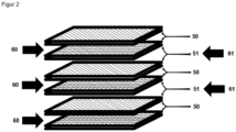
- the heat exchanger is an absorptive air-air cross-flow heat exchanger, which is characterized in that the heat exchanger has sorption channels in at least one flow direction, which have water-absorbing metal-organic framework materials as adsorption material, and has heat exchanger channels in at least one other flow direction, wherein the heat exchanger channels contain less than 5% adsorption material in relation to the loading of the sorption channels with adsorption material.
- the heat exchanger channels do not contain any adsorption material.
- the air-air cross-flow heat exchanger is advantageously designed in such a way that a plurality of sorption channels connected in parallel and a plurality of heat exchanger channels connected in parallel are arranged.
- the term parallel connection means that these flow channels each have a common inlet and a common outlet.
- the sorption channels and the heat exchanger channels of the sorber heat exchanger are preferably arranged alternately. Such an alternating arrangement enables optimized heat transfer within the heat exchanger. At the same time, mixing of the fluid flows is to be avoided.
- the channel width is advantageously 0.5 to 2 mm, in particular 0.7 to 1.5 mm.
- the channel width of the sorption channels and the heat exchanger channels can be different.
- the flow resistance of the sorption channels and the heat exchanger channels is advantageously the same.
- the sorption channels are therefore advantageously wider than the heat exchanger channels by twice the coating thickness of the adsorption material.
- the coating thickness of the adsorption material is advantageously 10 to 200 ⁇ m, preferably 20 to 150 ⁇ m, in particular 25 to 100 ⁇ m.
- the air-air cross-flow heat exchanger is advantageously used for conditioning fresh air, particularly in buildings or vehicles.
- the method for conditioning fluids and the corresponding air conditioning device are advantageously used for conditioning air for the air conditioning of buildings or vehicles, in particular trains and electric cars. This method and device are particularly advantageous for the air conditioning of hospitals, laboratories and other facilities where a 100 percent supply of fresh air is required.
- the present invention further relates to a facade element with a built-in air conditioning device according to the present invention.
- the compactness of the air conditioning device according to the invention enables installation in a facade element and thus the possibility for decentralized, flexible air conditioning. Furthermore, this decentralization enables individual, quasi-personalized control of the air conditioning, e.g. the temperature selection per facade element. This individual control could be carried out via app applications, for example.
- the advantage of the present invention lies in the synergy of the following features (i) use of an effective adsorption material, in particular an adsorption material with high loading capacity and low recycling temperatures, (ii) use of a regeneration fluid that has the largest possible temperature difference and humidity difference to the selected (regenerated) adsorption material and (iii) the use of the adsorption heat for the regeneration.
- Aluminium fumarate was prepared according to EP2 230 288 .
- a dispersion of 1300 g of aluminum fumarate and 3300 g of distilled water was prepared by stirring at 570 rpm with a toothed disk stirrer (7 cm disk diameter; Heidolph RZR2010control) for 15 minutes. After adding 810 g of polyacrylate dispersion (Acronal ® Edge, 40% solids content), the stirrer speed was increased to 740 rpm for 15 minutes. Five batches prepared in this way were stirred with a propeller stirrer (diameter 10 cm, IKA EURO ST 40DS0000) and homogenized for 12 hours. Foam was then removed and the dispersion was degassed by slow stirring.
- the dispersion had a viscosity of 4 Pa s at 10 Hz (measured with Anton Paar, MCR102, PP50, 400 ⁇ m gap, 25°C).
- the dispersion was filled twice through one of the two channel systems of a countercurrent heat exchanger made of aluminum (length 397 mm; height 172 mm; width 200 mm; channel width uncoated approx. 1 mm; Klingenburg GS18-200) and the channels were blown clean with air. After drying the heat exchanger, there was a weight increase of 346 g, which corresponded to an average layer thickness of 96 ⁇ m.
- a heat exchanger coated as in Example 1 was connected in such a way that air at 27°C and 90% relative humidity was passed through the coated channel bundle (1) (OL), and air at 20°C and 80% relative humidity was passed through the other channel bundle (IL).
- the flow rate was 50 m 3 /h.
- temperatures between 28°C and 32°C and a relative humidity between 35% and 50% were established on the outflow side of the coated channel bundle (KL).
- the enthalpy of the air was reduced almost isothermally from 80 kJ/kg to 63 kJ/kg.
- the outflow of the uncoated duct bundle (AL) showed a temperature increase to 30°C.
- the enthalpy of this air flow increased from approx. 51 kJ/m 3 to approx. 63 kJ/m 3 .
- the heat exchanger warmed up by 10°. Within the first 5 minutes, 60 kJ/m 3 were transferred from the outside air flow (OL ⁇ KL) to the inside air flow (IL ⁇ AL), which corresponds to approximately 50% of the adsorption enthalpy of water on aluminum fumarate.
- Example 2 The heat exchanger from Example 2 was flushed with hot, dry air (90°C, 3% relative humidity) for 5 minutes. The experiment from Example 2 was then repeated. On the outflow side of the coated channel bundle, temperatures between 27°C and 33°C and between 40 and 50% relative humidity were measured within the first 5 minutes.
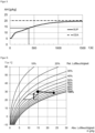
- the humidity of the outside air is 20 g/kg, that of the supply air (SUP) varies with the saturation of the adsorber. With a regenerated adsorber the humidity is 5g/kg, with long periods it approaches the outside air.
- the curve can be characterized by the half-life, shown here by the lines at 13 g/kg and approx. 350 s.
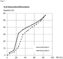
- FIG. 6 Adsorption and desorption curve of aluminum fumarate MOF.
- the diagram shows the equilibrium state of the loading of MOF with water as a function of the relative humidity.
- the MOFs are characterized by a two-part curve: Below 20% relative humidity, the MOF does not absorb water vapor, ie it does not overdry the air. Between 20 and 40% relative humidity, the MOF absorbs up to 30% of its own weight in humidity. At even higher relative humidities, there is further continuous water absorption.
- the diagram shows the possible combinations of absolute humidity and temperature.
- the influence of humidity on the density of the air is omitted (this effect would cause the isotherms (states of equal temperature) to rise slightly from left to right.)
- the ability of air to absorb water vapor increases with increasing temperature.
- the saturation curve is given as 100% relative humidity. Below this temperature, humidity condenses as fog. Therefore, it is also called the "fog curve".
- the comfort range for office spaces is between 40% relative humidity / 20°C and 60% relative humidity / 26°C.
- a typical outdoor climate in a warm, humid climate is, for example, the point with 30°C and 80% relative humidity (approx. 23g/kg water vapor).
- the air In order to reach the indoor comfort level, the air must first be dried. In established air conditioning technology, this is done by cooling to approx. 10°C, so that the humidity condenses until the absolute humidity is approx. 10-12 g/kg (fog curve).
- the coated heat exchanger allows the air to be dried almost isothermally without cooling.
- Drying without a heat exchanger would lead to an increase in the temperature of the air due to the release of the condensation and adsorption enthalpy of the water.
Landscapes
- Engineering & Computer Science (AREA)
- Chemical & Material Sciences (AREA)
- Mechanical Engineering (AREA)
- General Engineering & Computer Science (AREA)
- Combustion & Propulsion (AREA)
- Sustainable Development (AREA)
- Life Sciences & Earth Sciences (AREA)
- Chemical Kinetics & Catalysis (AREA)
- Oil, Petroleum & Natural Gas (AREA)
- General Chemical & Material Sciences (AREA)
- Analytical Chemistry (AREA)
- Physics & Mathematics (AREA)
- Thermal Sciences (AREA)
- Central Air Conditioning (AREA)
- Drying Of Gases (AREA)
- Sorption Type Refrigeration Machines (AREA)
- Other Air-Conditioning Systems (AREA)
Applications Claiming Priority (2)
| Application Number | Priority Date | Filing Date | Title |
|---|---|---|---|
| EP17174210 | 2017-06-02 | ||
| PCT/EP2018/064209 WO2018220027A1 (de) | 2017-06-02 | 2018-05-30 | Klimatisierungsverfahren und -vorrichtung |
Publications (3)
| Publication Number | Publication Date |
|---|---|
| EP3631308A1 EP3631308A1 (de) | 2020-04-08 |
| EP3631308C0 EP3631308C0 (de) | 2024-09-11 |
| EP3631308B1 true EP3631308B1 (de) | 2024-09-11 |
Family
ID=59009560
Family Applications (1)
| Application Number | Title | Priority Date | Filing Date |
|---|---|---|---|
| EP18729082.0A Active EP3631308B1 (de) | 2017-06-02 | 2018-05-30 | Klimatisierungsverfahren und -vorrichtung |
Country Status (10)
| Country | Link |
|---|---|
| US (1) | US11609000B2 (enExample) |
| EP (1) | EP3631308B1 (enExample) |
| JP (1) | JP7076477B2 (enExample) |
| KR (1) | KR102565093B1 (enExample) |
| CN (1) | CN110678698B (enExample) |
| BR (1) | BR112019024204A2 (enExample) |
| ES (1) | ES2997122T3 (enExample) |
| PH (1) | PH12019502622A1 (enExample) |
| TW (1) | TWI768054B (enExample) |
| WO (1) | WO2018220027A1 (enExample) |
Families Citing this family (4)
| Publication number | Priority date | Publication date | Assignee | Title |
|---|---|---|---|---|
| US11859863B2 (en) | 2019-08-16 | 2024-01-02 | Battelle Memorial Institute | Method and system for dehumidification and atmospheric water extraction with minimal energy consumption |
| US11592195B2 (en) | 2021-02-12 | 2023-02-28 | Trane International Inc. | Dehumidifying air handling unit and desiccant wheel therefor |
| JP7632247B2 (ja) * | 2021-11-26 | 2025-02-19 | 株式会社豊田中央研究所 | 吸着器、および、吸着式多段ヒートポンプ |
| FR3142240B1 (fr) * | 2022-11-17 | 2024-11-22 | Eos Innovare | procédé de refroidissement et de déshumidification d’un mélange gazeux de vapeur d’eau et d’au moins un gaz- installation associée |
Family Cites Families (35)
| Publication number | Priority date | Publication date | Assignee | Title |
|---|---|---|---|---|
| US4460388A (en) * | 1981-07-17 | 1984-07-17 | Nippon Soken, Inc. | Total heat exchanger |
| JPS62261892A (ja) * | 1986-05-08 | 1987-11-14 | Toshiba Corp | 熱交換器 |
| US5170633A (en) | 1991-06-24 | 1992-12-15 | Amsted Industries Incorporated | Desiccant based air conditioning system |
| US5648508A (en) | 1995-11-22 | 1997-07-15 | Nalco Chemical Company | Crystalline metal-organic microporous materials |
| JPH09318127A (ja) * | 1996-05-24 | 1997-12-12 | Ebara Corp | 空調システム |
| US6199392B1 (en) | 1997-03-25 | 2001-03-13 | Ebara Corporation | Air conditioning system |
| JPH11197439A (ja) | 1998-01-14 | 1999-07-27 | Ebara Corp | 除湿空調装置 |
| DE10111230A1 (de) | 2001-03-08 | 2002-09-19 | Basf Ag | Metallorganische Gerüstmaterialien und Verfahren zu deren Herstellung |
| JP2003097825A (ja) | 2001-07-18 | 2003-04-03 | Daikin Ind Ltd | 空気調和装置 |
| DE10220631A1 (de) * | 2002-05-10 | 2003-11-20 | Loeffler Michael | Verfahren zur Sorptionsklimatisierung mit Prozeßführung in einem Wärmetauscher |
| JP2005095883A (ja) * | 2003-09-04 | 2005-04-14 | Mitsubishi Chemicals Corp | 吸着ヒートポンプ又はデシカント空調装置用吸着材 |
| DE10355087A1 (de) | 2003-11-24 | 2005-06-09 | Basf Ag | Verfahren zur elektrochemischen Herstellung eines kristallinen porösen metallorganischen Gerüstmaterials |
| DE102005039623A1 (de) | 2005-08-22 | 2007-03-01 | Basf Ag | Verfahren zur Herstellung von metallorganischen Gerüstmaterialien Hauptgruppen Metallionen enthaltend |
| DE102005053430A1 (de) | 2005-11-09 | 2007-05-16 | Basf Ag | Dotierte metallorganische Gerüstmaterialien |
| DE102005054523A1 (de) | 2005-11-14 | 2007-05-16 | Basf Ag | Poröses metallorganisches Gerüstmaterial enthaltend ein weiteres Polymer |
| CN101004340A (zh) * | 2006-12-15 | 2007-07-25 | 天津市泰来暖通设备有限公司 | 一种内腔防腐层真空吸附涂覆工艺及装置 |
| CN201096388Y (zh) * | 2007-06-06 | 2008-08-06 | 重庆大学 | 一种多功能空调装置 |
| CN101140089B (zh) * | 2007-10-26 | 2010-05-26 | 重庆大学 | 一种温湿度独立控制空调系统 |
| JP4502065B1 (ja) | 2009-01-30 | 2010-07-14 | ダイキン工業株式会社 | ドレンレス空気調和装置 |
| PL2230288T3 (pl) | 2009-03-20 | 2016-12-30 | Metaloorganiczne materiały szkieletowe w urządzeniach chłodzących/grzejnych | |
| US20120043064A1 (en) * | 2009-04-28 | 2012-02-23 | Mitsubishi Electric Corporation | Total heat exchange element |
| JP2011075180A (ja) * | 2009-09-30 | 2011-04-14 | Sanyo Electric Co Ltd | 吸収式冷凍機 |
| DE102009050050A1 (de) | 2009-10-21 | 2011-04-28 | Robert Bosch Gmbh | Sorptionswärmetauscher und Verfahren hierfür |
| DE102009057159B4 (de) * | 2009-12-05 | 2014-02-20 | Robert Bosch Gmbh | Sorptionswärmetauscher und Steuerung hierfür |
| DE102010024624B4 (de) * | 2010-06-22 | 2016-03-31 | Robert Bosch Gmbh | Verfahren zum Betrieb einer Sorptionswärmetauscheranlage und Sorptionswärmetauscheranlage hierfür |
| DE102011011688A1 (de) * | 2011-02-18 | 2012-08-23 | Fraunhofer-Gesellschaft zur Förderung der angewandten Forschung e.V. | Verfahren zur Beschichtung einer Wärmetauscherstruktur, beschichtete Wärmetauscherstruktur und deren Verwendung |
| WO2013059785A1 (en) * | 2011-10-21 | 2013-04-25 | Massachusetts Institute Of Technology | Adsorption system |
| UA69450U (en) * | 2011-11-07 | 2012-04-25 | Институт Технической Теплофизики Нан Украины | Adsorption air drier |
| CN103574790B (zh) * | 2013-10-17 | 2016-01-20 | 陕西科技大学 | 一种除湿空气冷却装置及冷却方法 |
| KR101441486B1 (ko) * | 2013-11-18 | 2014-09-17 | 한국과학기술연구원 | 흡수식 냉동기 및 제습 냉방기를 이용한 냉방 장치 |
| CN103673111B (zh) * | 2013-12-16 | 2015-12-02 | 内蒙古科技大学 | 多功能空气除湿净化固体吸附再生床 |
| FR3026163A1 (fr) * | 2014-09-18 | 2016-03-25 | Mof Applic Services | Utilisations de materiau metallo-organique (mof) dans un systeme de refroidissement/chauffage par adsorption |
| CN106610064A (zh) * | 2015-10-22 | 2017-05-03 | 南通航运职业技术学院 | 一种节能型转轮余热回收装置及使用方法 |
| JP2019504271A (ja) | 2015-11-18 | 2019-02-14 | ビーエーエスエフ ソシエタス・ヨーロピアBasf Se | 建物内の換気システムとしての熱回収吸着体 |
| CN206037293U (zh) * | 2016-08-30 | 2017-03-22 | 天津市万丰化工设备有限公司 | 带有再生预处理装置与气‑气换热器的热泵驱动的溶液调湿机组 |
-
2018
- 2018-05-30 CN CN201880034957.4A patent/CN110678698B/zh active Active
- 2018-05-30 ES ES18729082T patent/ES2997122T3/es active Active
- 2018-05-30 US US16/618,767 patent/US11609000B2/en active Active
- 2018-05-30 EP EP18729082.0A patent/EP3631308B1/de active Active
- 2018-05-30 KR KR1020207000064A patent/KR102565093B1/ko active Active
- 2018-05-30 BR BR112019024204-0A patent/BR112019024204A2/pt not_active Application Discontinuation
- 2018-05-30 JP JP2019566627A patent/JP7076477B2/ja active Active
- 2018-05-30 WO PCT/EP2018/064209 patent/WO2018220027A1/de not_active Ceased
- 2018-06-01 TW TW107118940A patent/TWI768054B/zh active
-
2019
- 2019-11-21 PH PH12019502622A patent/PH12019502622A1/en unknown
Also Published As
| Publication number | Publication date |
|---|---|
| EP3631308A1 (de) | 2020-04-08 |
| US20210080131A1 (en) | 2021-03-18 |
| ES2997122T3 (en) | 2025-02-14 |
| EP3631308C0 (de) | 2024-09-11 |
| PH12019502622A1 (en) | 2021-08-09 |
| KR102565093B1 (ko) | 2023-08-10 |
| JP2020521940A (ja) | 2020-07-27 |
| TWI768054B (zh) | 2022-06-21 |
| BR112019024204A2 (pt) | 2020-06-02 |
| US11609000B2 (en) | 2023-03-21 |
| WO2018220027A1 (de) | 2018-12-06 |
| JP7076477B2 (ja) | 2022-05-27 |
| CN110678698B (zh) | 2022-02-25 |
| TW201903337A (zh) | 2019-01-16 |
| CN110678698A (zh) | 2020-01-10 |
| KR20200015694A (ko) | 2020-02-12 |
Similar Documents
| Publication | Publication Date | Title |
|---|---|---|
| DE60311090T2 (de) | Sorptionswärmetauscher und ein entsprechendes verfahren | |
| DE112008000905B4 (de) | Entfeuchter/Befeuchter für ein Fahrzeug | |
| Mazzei et al. | HVAC dehumidification systems for thermal comfort: A critical review | |
| DE60126834T2 (de) | Entfeuchtigungs- und klimaanlage | |
| EP3631308B1 (de) | Klimatisierungsverfahren und -vorrichtung | |
| DE60017715T2 (de) | Verfahren und vorrichtung zur regelung der lufttemperatur und der luftfeuchte | |
| DE112013006529B4 (de) | Entfeuchter | |
| CN110709643B (zh) | 换气系统 | |
| DE10059910C2 (de) | Vorrichtung zur kontinuierlichen Befeuchtung und Entfeuchtung der Zuluft von Fertigungsprozessen oder Raumlufttechnik-Anlagen | |
| EP1575693B1 (de) | Verfahren und vorrichtung zum abführen und entfeuchten von luft an einer kochstelle | |
| DE19900846A1 (de) | Kraftfahrzeug-Entfeuchter mit Trocknungsmittel und regenerative Regelung des Trocknungsmittels | |
| DE4220715A1 (de) | Auf einem trockenmittel basierende klimaanlage | |
| WO2012084430A1 (de) | Klimatisierungsvorrichtung für ein fahrzeug und verfahren zum regeln eines klimas in einer fahrgastzelle eines fahrzeugs | |
| DE112016001274T5 (de) | Befeuchtungsvorrichtung und Klimaanlage für Fahrzeug | |
| EP2650426B1 (de) | Kondensationstrockner | |
| DE102010024624B4 (de) | Verfahren zum Betrieb einer Sorptionswärmetauscheranlage und Sorptionswärmetauscheranlage hierfür | |
| EP1271066B1 (de) | Raumlufttechnisches Verfahren und raumlufttechnische Anlage | |
| DE112016001281T5 (de) | Befeuchtungsvorrichtung und Klimaanlage für Fahrzeug | |
| DE10130731A1 (de) | Adsorptions-Innenraumfilter mit zyklischer Regenerierung für Kraftfahrzeuge | |
| DE10301315A1 (de) | Klimaanlage für ein Kraftfahrzeug | |
| DE202023104720U1 (de) | Entfeuchtungseinheit und Trockenmitteltrommel darin | |
| Shah et al. | Comparative study and analysis of HVAC systems using solid and liquid desiccant dehumidification technology | |
| DE102010022441A1 (de) | Kraftfahrzeug mit einer Innenraumluftentfeuchtungseinrichtung | |
| Sankhe et al. | Comparative Study and Analysis of HVAC Systems Using Solid and Liquid | |
| DE102022124981A1 (de) | Adsorptionstrockner zum Trocknen von Luft |
Legal Events
| Date | Code | Title | Description |
|---|---|---|---|
| STAA | Information on the status of an ep patent application or granted ep patent |
Free format text: STATUS: UNKNOWN |
|
| STAA | Information on the status of an ep patent application or granted ep patent |
Free format text: STATUS: THE INTERNATIONAL PUBLICATION HAS BEEN MADE |
|
| PUAI | Public reference made under article 153(3) epc to a published international application that has entered the european phase |
Free format text: ORIGINAL CODE: 0009012 |
|
| STAA | Information on the status of an ep patent application or granted ep patent |
Free format text: STATUS: REQUEST FOR EXAMINATION WAS MADE |
|
| 17P | Request for examination filed |
Effective date: 20200102 |
|
| AK | Designated contracting states |
Kind code of ref document: A1 Designated state(s): AL AT BE BG CH CY CZ DE DK EE ES FI FR GB GR HR HU IE IS IT LI LT LU LV MC MK MT NL NO PL PT RO RS SE SI SK SM TR |
|
| AX | Request for extension of the european patent |
Extension state: BA ME |
|
| DAV | Request for validation of the european patent (deleted) | ||
| DAX | Request for extension of the european patent (deleted) | ||
| STAA | Information on the status of an ep patent application or granted ep patent |
Free format text: STATUS: EXAMINATION IS IN PROGRESS |
|
| 17Q | First examination report despatched |
Effective date: 20220405 |
|
| GRAP | Despatch of communication of intention to grant a patent |
Free format text: ORIGINAL CODE: EPIDOSNIGR1 |
|
| STAA | Information on the status of an ep patent application or granted ep patent |
Free format text: STATUS: GRANT OF PATENT IS INTENDED |
|
| RIC1 | Information provided on ipc code assigned before grant |
Ipc: F28F 13/18 20060101ALI20240313BHEP Ipc: F28D 9/00 20060101ALI20240313BHEP Ipc: F25B 21/00 20060101ALI20240313BHEP Ipc: B01D 53/26 20060101ALI20240313BHEP Ipc: F24F 12/00 20060101ALI20240313BHEP Ipc: C09K 5/04 20060101ALI20240313BHEP Ipc: B01D 53/02 20060101ALI20240313BHEP Ipc: F24F 5/00 20060101ALI20240313BHEP Ipc: F24F 3/14 20060101AFI20240313BHEP |
|
| INTG | Intention to grant announced |
Effective date: 20240404 |
|
| P01 | Opt-out of the competence of the unified patent court (upc) registered |
Free format text: CASE NUMBER: APP_35573/2024 Effective date: 20240613 |
|
| GRAS | Grant fee paid |
Free format text: ORIGINAL CODE: EPIDOSNIGR3 |
|
| GRAA | (expected) grant |
Free format text: ORIGINAL CODE: 0009210 |
|
| STAA | Information on the status of an ep patent application or granted ep patent |
Free format text: STATUS: THE PATENT HAS BEEN GRANTED |
|
| AK | Designated contracting states |
Kind code of ref document: B1 Designated state(s): AL AT BE BG CH CY CZ DE DK EE ES FI FR GB GR HR HU IE IS IT LI LT LU LV MC MK MT NL NO PL PT RO RS SE SI SK SM TR |
|
| REG | Reference to a national code |
Ref country code: GB Ref legal event code: FG4D Free format text: NOT ENGLISH |
|
| REG | Reference to a national code |
Ref country code: CH Ref legal event code: EP |
|
| REG | Reference to a national code |
Ref country code: DE Ref legal event code: R096 Ref document number: 502018015122 Country of ref document: DE |
|
| REG | Reference to a national code |
Ref country code: IE Ref legal event code: FG4D Free format text: LANGUAGE OF EP DOCUMENT: GERMAN |
|
| U01 | Request for unitary effect filed |
Effective date: 20240926 |
|
| U07 | Unitary effect registered |
Designated state(s): AT BE BG DE DK EE FI FR IT LT LU LV MT NL PT RO SE SI Effective date: 20241022 |
|
| P04 | Withdrawal of opt-out of the competence of the unified patent court (upc) registered |
Free format text: CASE NUMBER: APP_56893/2024 Effective date: 20241018 |
|
| U1N | Appointed representative for the unitary patent procedure changed after the registration of the unitary effect |
Representative=s name: BASF IP ASSOCIATION; DE |
|
| PG25 | Lapsed in a contracting state [announced via postgrant information from national office to epo] |
Ref country code: NO Free format text: LAPSE BECAUSE OF FAILURE TO SUBMIT A TRANSLATION OF THE DESCRIPTION OR TO PAY THE FEE WITHIN THE PRESCRIBED TIME-LIMIT Effective date: 20241211 |
|
| PG25 | Lapsed in a contracting state [announced via postgrant information from national office to epo] |
Ref country code: GR Free format text: LAPSE BECAUSE OF FAILURE TO SUBMIT A TRANSLATION OF THE DESCRIPTION OR TO PAY THE FEE WITHIN THE PRESCRIBED TIME-LIMIT Effective date: 20241212 |
|
| PG25 | Lapsed in a contracting state [announced via postgrant information from national office to epo] |
Ref country code: HR Free format text: LAPSE BECAUSE OF FAILURE TO SUBMIT A TRANSLATION OF THE DESCRIPTION OR TO PAY THE FEE WITHIN THE PRESCRIBED TIME-LIMIT Effective date: 20240911 |
|
| PG25 | Lapsed in a contracting state [announced via postgrant information from national office to epo] |
Ref country code: RS Free format text: LAPSE BECAUSE OF FAILURE TO SUBMIT A TRANSLATION OF THE DESCRIPTION OR TO PAY THE FEE WITHIN THE PRESCRIBED TIME-LIMIT Effective date: 20241211 |
|
| PG25 | Lapsed in a contracting state [announced via postgrant information from national office to epo] |
Ref country code: RS Free format text: LAPSE BECAUSE OF FAILURE TO SUBMIT A TRANSLATION OF THE DESCRIPTION OR TO PAY THE FEE WITHIN THE PRESCRIBED TIME-LIMIT Effective date: 20241211 Ref country code: NO Free format text: LAPSE BECAUSE OF FAILURE TO SUBMIT A TRANSLATION OF THE DESCRIPTION OR TO PAY THE FEE WITHIN THE PRESCRIBED TIME-LIMIT Effective date: 20241211 Ref country code: HR Free format text: LAPSE BECAUSE OF FAILURE TO SUBMIT A TRANSLATION OF THE DESCRIPTION OR TO PAY THE FEE WITHIN THE PRESCRIBED TIME-LIMIT Effective date: 20240911 Ref country code: GR Free format text: LAPSE BECAUSE OF FAILURE TO SUBMIT A TRANSLATION OF THE DESCRIPTION OR TO PAY THE FEE WITHIN THE PRESCRIBED TIME-LIMIT Effective date: 20241212 |
|
| REG | Reference to a national code |
Ref country code: ES Ref legal event code: FG2A Ref document number: 2997122 Country of ref document: ES Kind code of ref document: T3 Effective date: 20250214 |
|
| PG25 | Lapsed in a contracting state [announced via postgrant information from national office to epo] |
Ref country code: IS Free format text: LAPSE BECAUSE OF FAILURE TO SUBMIT A TRANSLATION OF THE DESCRIPTION OR TO PAY THE FEE WITHIN THE PRESCRIBED TIME-LIMIT Effective date: 20250111 |
|
| PG25 | Lapsed in a contracting state [announced via postgrant information from national office to epo] |
Ref country code: SM Free format text: LAPSE BECAUSE OF FAILURE TO SUBMIT A TRANSLATION OF THE DESCRIPTION OR TO PAY THE FEE WITHIN THE PRESCRIBED TIME-LIMIT Effective date: 20240911 |
|
| PG25 | Lapsed in a contracting state [announced via postgrant information from national office to epo] |
Ref country code: CZ Free format text: LAPSE BECAUSE OF FAILURE TO SUBMIT A TRANSLATION OF THE DESCRIPTION OR TO PAY THE FEE WITHIN THE PRESCRIBED TIME-LIMIT Effective date: 20240911 Ref country code: PL Free format text: LAPSE BECAUSE OF FAILURE TO SUBMIT A TRANSLATION OF THE DESCRIPTION OR TO PAY THE FEE WITHIN THE PRESCRIBED TIME-LIMIT Effective date: 20240911 |
|
| PG25 | Lapsed in a contracting state [announced via postgrant information from national office to epo] |
Ref country code: SK Free format text: LAPSE BECAUSE OF FAILURE TO SUBMIT A TRANSLATION OF THE DESCRIPTION OR TO PAY THE FEE WITHIN THE PRESCRIBED TIME-LIMIT Effective date: 20240911 |
|
| U20 | Renewal fee for the european patent with unitary effect paid |
Year of fee payment: 8 Effective date: 20250602 |
|
| PGFP | Annual fee paid to national office [announced via postgrant information from national office to epo] |
Ref country code: GB Payment date: 20250520 Year of fee payment: 8 Ref country code: ES Payment date: 20250611 Year of fee payment: 8 |
|
| PLBE | No opposition filed within time limit |
Free format text: ORIGINAL CODE: 0009261 |
|
| STAA | Information on the status of an ep patent application or granted ep patent |
Free format text: STATUS: NO OPPOSITION FILED WITHIN TIME LIMIT |
|
| PGFP | Annual fee paid to national office [announced via postgrant information from national office to epo] |
Ref country code: TR Payment date: 20250512 Year of fee payment: 8 |
|
| 26N | No opposition filed |
Effective date: 20250612 |