EP3630541B1 - Schalter mit umlenkhebel und grossem schaltweg - Google Patents
Schalter mit umlenkhebel und grossem schaltweg Download PDFInfo
- Publication number
- EP3630541B1 EP3630541B1 EP18722432.4A EP18722432A EP3630541B1 EP 3630541 B1 EP3630541 B1 EP 3630541B1 EP 18722432 A EP18722432 A EP 18722432A EP 3630541 B1 EP3630541 B1 EP 3630541B1
- Authority
- EP
- European Patent Office
- Prior art keywords
- lever
- switch
- bearing
- switching
- movement
- Prior art date
- Legal status (The legal status is an assumption and is not a legal conclusion. Google has not performed a legal analysis and makes no representation as to the accuracy of the status listed.)
- Active
Links
Images
Classifications
-
- B—PERFORMING OPERATIONS; TRANSPORTING
- B60—VEHICLES IN GENERAL
- B60Q—ARRANGEMENT OF SIGNALLING OR LIGHTING DEVICES, THE MOUNTING OR SUPPORTING THEREOF OR CIRCUITS THEREFOR, FOR VEHICLES IN GENERAL
- B60Q1/00—Arrangement of optical signalling or lighting devices, the mounting or supporting thereof or circuits therefor
- B60Q1/02—Arrangement of optical signalling or lighting devices, the mounting or supporting thereof or circuits therefor the devices being primarily intended to illuminate the way ahead or to illuminate other areas of way or environments
- B60Q1/04—Arrangement of optical signalling or lighting devices, the mounting or supporting thereof or circuits therefor the devices being primarily intended to illuminate the way ahead or to illuminate other areas of way or environments the devices being headlights
- B60Q1/14—Arrangement of optical signalling or lighting devices, the mounting or supporting thereof or circuits therefor the devices being primarily intended to illuminate the way ahead or to illuminate other areas of way or environments the devices being headlights having dimming means
- B60Q1/1446—Arrangement of optical signalling or lighting devices, the mounting or supporting thereof or circuits therefor the devices being primarily intended to illuminate the way ahead or to illuminate other areas of way or environments the devices being headlights having dimming means controlled by mechanically actuated switches
- B60Q1/1453—Hand actuated switches
- B60Q1/1461—Multifunction switches for dimming headlights and controlling additional devices, e.g. for controlling direction indicating lights
- B60Q1/1469—Multifunction switches for dimming headlights and controlling additional devices, e.g. for controlling direction indicating lights controlled by or attached to a single lever, e.g. steering column stalk switches
-
- B—PERFORMING OPERATIONS; TRANSPORTING
- B60—VEHICLES IN GENERAL
- B60Q—ARRANGEMENT OF SIGNALLING OR LIGHTING DEVICES, THE MOUNTING OR SUPPORTING THEREOF OR CIRCUITS THEREFOR, FOR VEHICLES IN GENERAL
- B60Q1/00—Arrangement of optical signalling or lighting devices, the mounting or supporting thereof or circuits therefor
- B60Q1/0076—Switches therefor
-
- B—PERFORMING OPERATIONS; TRANSPORTING
- B62—LAND VEHICLES FOR TRAVELLING OTHERWISE THAN ON RAILS
- B62D—MOTOR VEHICLES; TRAILERS
- B62D1/00—Steering controls, i.e. means for initiating a change of direction of the vehicle
- B62D1/02—Steering controls, i.e. means for initiating a change of direction of the vehicle vehicle-mounted
- B62D1/16—Steering columns
-
- H—ELECTRICITY
- H03—ELECTRONIC CIRCUITRY
- H03K—PULSE TECHNIQUE
- H03K17/00—Electronic switching or gating, i.e. not by contact-making and –breaking
- H03K17/94—Electronic switching or gating, i.e. not by contact-making and –breaking characterised by the way in which the control signals are generated
- H03K17/965—Switches controlled by moving an element forming part of the switch
- H03K17/97—Switches controlled by moving an element forming part of the switch using a magnetic movable element
-
- H—ELECTRICITY
- H03—ELECTRONIC CIRCUITRY
- H03K—PULSE TECHNIQUE
- H03K17/00—Electronic switching or gating, i.e. not by contact-making and –breaking
- H03K17/94—Electronic switching or gating, i.e. not by contact-making and –breaking characterised by the way in which the control signals are generated
- H03K17/965—Switches controlled by moving an element forming part of the switch
- H03K17/97—Switches controlled by moving an element forming part of the switch using a magnetic movable element
- H03K17/972—Switches controlled by moving an element forming part of the switch using a magnetic movable element having a plurality of control members, e.g. keyboard
Definitions
- the present invention relates to a switch, in particular as a steering column switch for arrangement on a steering column of a vehicle according to the preamble of claim 1.
- the present invention relates to a vehicle having the above switch.
- Steering column switches are switches equipped with a gearshift lever that are mounted on the steering column of a vehicle between the dashboard and the steering wheel.
- steering column switches can be directly connected to a control unit on the steering column, which can immediately convert various states on the gearshift lever into corresponding switching signals.
- the switching signals can be transmitted via a vehicle bus, for example.
- Bus systems such as CAN, LIN, or Flexray are well-known.
- Direction indicators also known as turn signals
- vehicle lighting including low beam, high beam and possibly headlight flasher, as well as windshield wiper and washer controls.
- steering column switches are known as control elements for automatic cruise control, also known as cruise control, or the remote control of car radios.
- each gear lever several functions can be realized, which can be triggered by tangential movement with a detent or tip function, such as with the direction indicator, by pulling against a resistance for the headlight flasher or by pressing with a detent for the high beam.
- switches with magnetic actuation are also known.
- a switching element is attached to the inside of the switching lever, extending radially from the switching lever, and a magnetic signaling element is attached to its tip. The position of the signaling element is detected by a magnetic sensor.
- a disadvantage of these switches is that distinguishing between different switch positions is directly dependent on the movement of the switching element, whose movement, in turn, is directly dependent on the movement of the switching lever. Therefore, a long switching element is required to reliably distinguish between switch positions, which in turn requires a large amount of installation space.
- the DE 199 22 500 A1 a switch device is known, in particular for motor vehicles, in which an actuation of the actuating element is detected without contact and the switch device is designed as a module.
- the DE 10 2005 018 289 A1 a switch is known, in particular a steering column switch for arrangement on a steering column of a vehicle, with an actuatable gearshift lever, with a switching element which is coupled in movement to the gearshift lever, wherein one switching element can be pivoted about at least two axes arranged transversely to one another and has differently polarized magnet sections in the region of its surface, and with an electronic unit having magnetic field sensors, wherein the respective switching position of one switching element can be detected via the magnetic field sensors and a corresponding switching process can be initiated and wherein a wall is arranged between the one switching element and the magnetic field sensors, which wall is penetrated by the magnetic field emanating from the switching element.
- the object of the invention is to provide a switch of the above-mentioned type and a vehicle with such a switch, which enable easy differentiation between different switch positions and require only minimal installation space.
- a switch is thus specified, in particular as a steering column switch for arrangement on a steering column of a vehicle, with an actuatable shift lever which has a bearing element along its longitudinal axis, with which the shift lever is movably mounted in a bearing of a base housing, a switching element which is movement-coupled to the shift lever and which is designed with a contactless signaling element, wherein the shift lever is actuatable on a first side of the bearing element, the switching element is arranged on a second side of the bearing element, the switching element is designed as a deflection lever with a first and a second lever arm, the deflection lever is rotatably held on the base housing in a deflection bearing in the connecting region of the first and second lever arms, the signaling element is arranged on the first lever arm, and the second lever arm is coupled to the shift lever.
- a vehicle with a switch as above is also provided.
- the basic idea of the present invention is to decouple the movement of the switching lever from the movement of the signaling element by designing the switching element as a bell crank. This allows the switch to be designed with a small installation space, since the movement of the signaling element can be realized as desired thanks to the design of the bell crank.
- the shift lever can be designed as a simple, straight lever. However, it is also possible for the shift lever to have any other shape. Sections of the shift lever on the first and second sides can also be arranged not in a line, but with an angular offset in essentially any direction.
- the bearing element is designed depending on the degrees of freedom of movement of the gear lever, for example for movable mounting around one or two axes of the gear lever.
- the coupling of the switching element to the switching lever is designed in such a way that a movement of the switching lever on its second side causes a movement of the reversing lever, with the resulting movement of the signaling element.
- the base housing can also house the bearing element.
- the base housing provides a structure to which the switch components can be permanently attached.
- the switching element can be designed with the first and a second lever arm in such a way that the first and second lever arms can, in principle, be at any angle to one another.
- the first and second lever arms are arranged such that they enclose an angle of approximately 90° between them.
- the shift lever can be pivoted about an axis, and the deflection lever converts the movement of the shift lever along one axis into a corresponding movement of the shifting element along another axis.
- both the bearing element and the deflection bearing can be designed simply, since they each only need to support a simple pivoting movement.
- the switching lever can be pivoted about two axes arranged transversely to each other, and the reversing lever converts the movement of the switching lever along the two axes into a movement of the switching element along two axes.
- the reversing lever converts the movement of the switching lever along the two axes into a movement of the switching element along two axes.
- the second lever arm is shorter than the first lever arm. Due to the shorter length of the second lever arm, a generally smaller movement of the shift lever can be converted into a larger movement of the signaling element, thereby increasing the shifting travel. This allows different positions of the shift lever to be easily detected using conventional sensors.
- the length of the respective lever arm refers to an effective lever length, i.e., a length from the deflection bearing to the signaling element or to a position of the coupling with the shift lever.
- the second lever arm has a longitudinal guide, with which the second lever arm is coupled to the shift lever so that it can be moved along the longitudinal axis of the shift lever.
- the longitudinal guide provides good mobility of the shifting element, which is particularly advantageous for movement around multiple axes.
- a movable coupling is formed between the second lever arm and the shift lever.
- the switching element and the bearing element are arranged on the switching lever axially offset in the direction of the longitudinal axis of the switching lever.
- the arrangement of the switching element on the switching lever is thus separate from the bearing in the bearing element. This allows the movement of the switching element and in particular of the signaling element to be freely designed.
- deflections of the switching lever can be amplified by the signaling element in order to improve the resolution of the switch or to be able to precisely define the response of the switch.
- the movement of the signaling element can be freely designed, in particular by combining it with the switching element designed as a deflection lever.
- the switching element is designed and arranged such that the second lever arm extends substantially in the direction of the bearing element and is coupled to the switching lever between the bearing element and the deflection bearing.
- the switching lever can be designed with a small extension in the longitudinal direction, whereby the switch can have a small overall size.
- the switching element can be designed and arranged such that the second lever arm extends substantially in the direction away from the bearing element. Accordingly, the second lever arm is coupled to the switching lever, starting from the deflection bearing on the side of the switching lever opposite the bearing element.
- the signaling element is a magnetic signaling element
- the switch has a magnetic sensor, to detect the movement of the signaling element.
- the magnetic sensor is designed to match the mobility of the signaling element.
- the magnetic sensor is preferably mounted on the housing.
- the magnetic sensor is a 3D magnetic sensor or a magnetic sensor array. This is advantageous for reliably detecting a movement of the gearshift lever around more than one axis through the corresponding movement of the signaling element.
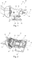
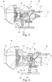
- the Figures 1 to 3 show a switch 10 designed as a steering column switch according to a first preferred embodiment of the invention.
- the switch 10 is designed for placement on a steering column (not shown) of a vehicle (also not shown).
- the switch 10 comprises an actuatable switching lever 12, which has a bearing element 16 along its longitudinal axis 14, by means of which the switching lever 12 is movably mounted in a bearing of a base housing 18.
- the bearing element 16 is held in the base housing 18.
- the shift lever 12 is designed with an angular offset on its first and second sides 34, 36.
- the first side 34 as viewed from the bearing element 16, relates to the side of the shift lever 12 on which the shift lever 12 can be actuated.
- the second side 36 relates to the correspondingly other side of the shift lever 12.
- the shift lever 12 is pivotable about two axes 50, 52 arranged transversely to one another. Accordingly, the bearing element 16 is designed in accordance with the degrees of freedom of movement of the shift lever 12 for the movable mounting of the shift lever 12 about the two axes 50, 52.
- the switch 10 comprises a switching element 30, which is designed as a deflection lever with a first and a second lever arm 40, 42.
- the switching element 30 is arranged on the second side 36 of the switching lever 12.
- the switching element 30 is arranged axially offset from the bearing element 16 on the switching lever 12 in the direction of the longitudinal axis 14 of the switching lever 12, whereby the arrangement of the switching element 30 on the switching lever 12 is separated from the bearing in the bearing element 16.
- the deflection bearing (46) of the switching element (30) and the bearing (20) of the bearing element (16) are arranged axially offset from one another on the switching lever (12) in the direction of the longitudinal axis (14) of the switching lever (12).
- the switching element 30 is designed such that the first and second lever arms 40, 42 form an angle of approximately 90° between them.
- a contactless signaling element 32 is arranged at a tip of the first lever arm 40, and the second lever arm 42 is coupled in motion to the switching lever 12.
- the coupling of the The switching element 30 with the switching lever 12 is designed such that a movement of the switching lever 12 on its second side 36 causes a movement of the switching element 30, with a resulting movement of the signaling element 32.
- the switching element 30 is rotatably mounted on the base housing 18 in a deflection bearing 46 in the connecting region 44 of the first and second lever arms 40, 42.
- the switching element 30 converts the movement of the switching lever 12 in the two axes 50, 52 into a movement of the signaling element 32 in two axes 50, 52.
- the signaling element 32 is a magnetic signaling element. Accordingly, the switch 10 includes a magnetic sensor 60 to detect the movement of the signaling element 32.
- the magnetic sensor 60 is designed as a 3D magnetic sensor or magnetic sensor array and is mounted on the base housing 18.
- the second lever arm 42 has a longitudinal guide 48, with which the second lever arm 42 is slidably coupled to the shift lever 12 in the direction of the longitudinal axis 14.
- a coupling element 39 is formed on the second side 36 of the shift lever 12, which coupling element is guided in the longitudinal guide 48 in order to couple the second lever arm 42 to the second side 36 of the shift lever 12 via the longitudinal guide 48 and the coupling element 39.
- the switching element 30 is designed and arranged such that its second lever arm 42 extends substantially in the direction of the bearing element 16.
- the switching element 30 is accordingly coupled to the switching lever 12 at the second lever arm 42 between the bearing element 16 and the deflection bearing 46.
- Fig. 4 shows a switch 10 according to a second embodiment of the invention.
- the switch 10 of the second embodiment is substantially identical to the switch 10 of the first embodiment. Accordingly, only differences between the switch 10 of the second embodiment and the switch 10 of the first embodiment will be described in detail. Details not described may be implemented as described with reference to the first embodiment.
- the switching element 30 is designed and arranged such that its second lever arm 42 extends substantially in the direction of extends away from the bearing element 16.
- the switching element 30 is correspondingly coupled to the second lever arm 42, as seen from the deflection bearing 46, on the side of the switching lever 12 opposite the bearing element 16.
Landscapes
- Engineering & Computer Science (AREA)
- Mechanical Engineering (AREA)
- Chemical & Material Sciences (AREA)
- Combustion & Propulsion (AREA)
- Transportation (AREA)
- Switches With Compound Operations (AREA)
- Arrangement Or Mounting Of Control Devices For Change-Speed Gearing (AREA)
Description
- Die vorliegende Erfindung betrifft einen Schalter, insbesondere als Lenkstockschalter zur Anordnung an einem Lenkstock eines Fahrzeuges gemäß der Präambel des Anspruchs 1.
- Des Weiteren betrifft die vorliegende Erfindung ein Fahrzeug mit einem obigen Schalter.
- Als Lenkstockschalter werden mit einem Schalthebel versehene Schalter bezeichnet, die am Lenkstock eines Fahrzeugs zwischen Armaturenbrett und Lenkrad angebracht sind. Lenkstockschalter können in modernen Fahrzeugen direkt mit einem Steuergerät am Lenkstock verbunden sein, welches verschiedene Zustände am Schalthebel unmittelbar in entsprechende Schaltsignale umwandeln kann. Die Schaltsignale können beispielsweise über einen Fahrzeugbus weiter übertragen werden. Als Bussystems sind beispielsweise CAN, LIN oder Flexray bekannt.
- Grundlegende Anwendungen für Lenkstockschalter sind Fahrtrichtungsanzeiger, auch als Blinker bekannt, Fahrzeugbeleuchtung umfassend Abblendlicht, Fernlicht und ggf. Lichthupe, sowie Scheibenwisch- und -Waschsteuerung.
- Darüber hinaus sind Lenkstockschalter als Bedienelemente für eine Geschwindigkeitsregelautomatik, auch Tempomat genannt, oder die Fernsteuerung von Autoradios bekannt.
- Mit jedem Schalthebel können dabei mehrere Funktionen realisiert werden, die durch tangentiale Bewegung mit Rast- oder Tippfunktion, wie beispielsweise beim Fahrtrichtungsanzeiger, durch Ziehen gegen einen Widerstand für die Lichthupe oder Drücken mit Raste für das Fernlicht ausgelöst werden können.
- Prinzipiell sind auch derartige Schalter mit einer Magnetbetätigung bekannt. Dabei ist an dem Schalthebel innenliegend ein Schaltglied angebracht, dass sich von dem Schalthebel radial erstreckt, und an dessen Spitze ein magnetisches Signalisierungselement angebracht ist. Die Position des Signalisierungselements wird von einem Magnetsensor erkannt. Nachteilig an diesen Schaltern ist jedoch, dass eine Unterscheidung verschiedener Schalterstellungen direkt abhängig von der Bewegung des Schaltglieds ist, dessen Bewegung wiederum direkt abhängig von der Bewegung des Schalthebels ist, so dass zur zuverlässigen Unterscheidung der Schalterpositionen eine große Länge der Schaltglieds erforderlich ist, was wiederum einen großen Bauraum erfordert.
- In diesem Zusammenhang ist aus der
DE 199 22 500 A1 eine Schaltervorrichtung bekannt, insbesondere für Kraftfahrzeuge, bei der eine Betätigung des Betätigungselements berührungslos erfasst wird und die Schaltervorrichtung als Modul ausgebildet ist. - Außerdem ist aus der
DE 10 2005 018 289 A1 ein Schalter bekannt, insbesondere Lenkstockschalter zur Anordnung an einen Lenkstock eines Fahrzeuges, mit einem betätigbaren Schalthebel, mit einem mit dem Schalthebel bewegungsgekoppelten Schaltglied, wobei das eine Schaltglied um wenigstens zwei quer zueinander angeordnete Achsen schwenkbar ist und im Bereich seiner Oberfläche verschieden polarisierte Magnetabschnitte aufweist, und mit einer Magnetfeldsensoren aufweisenden Elektronikeinheit, wobei über die Magnetfeldsensoren die jeweilige Schaltlage des einen Schaltglieds erfasst und ein entsprechender Schaltvorgang eingeleitet werden kann und wobei zwischen dem einen Schaltglied und den Magnetfeldsensoren eine Wandung angeordnet ist, die von dem vom Schaltglied ausgehenden Magnetfeld durchdrungen wird. - Weitere Lenkstockschalter sind aus
JP 2017 016920 A JP 2015 176652 A - Die Lösung der Aufgabe erfolgt erfindungsgemäß durch die Merkmale der unabhängigen Ansprüche. Vorteilhafte Ausgestaltungen der Erfindung sind in den Unteransprüchen angegeben.
- Erfindungsgemäß ist somit ein Schalter angegeben, insbesondere als Lenkstockschalter zur Anordnung an einem Lenkstock eines Fahrzeuges, mit einem betätigbaren Schalthebel, der entlang seiner Längsachse ein Lagerelement aufweist, mit dem der Schalthebel in einem Lager eines Grundgehäuses beweglich gelagert ist, einem mit dem Schalthebel bewegungsgekoppelten Schaltglied, das mit einem berührungslosen Signalisierungselement ausgeführt ist, wobei der Schalthebel auf einer ersten Seite des Lagerelements betätigbar ist, das Schaltglied auf einer zweiten Seite des Lagerelements angeordnet ist, das Schaltglied als Umlenkhebel mit einem ersten und einem zweiten Hebelarm ausgeführt ist, der Umlenkhebel im Verbindungsbereich des ersten und zweiten Hebelarms in einem Umlenklager drehbar an dem Grundgehäuse gehalten ist, an dem ersten Hebelarm das Signalisierungselement angeordnet ist, und der zweite Hebelarm mit dem Schalthebel gekoppelt ist.
- Erfindungsgemäß ist außerdem ein Fahrzeug mit einem obigen Schalter angegeben.
- Grundidee der vorliegenden Erfindung ist es also, durch die Ausgestaltung des Schaltglieds als Umlenkhebel die Bewegung des Schalthebels von der Bewegung des Signalisierungselements zu entkoppeln. Dadurch kann er Schalter mit kleinem Bauraum ausgeführt werden, da die Bewegung des Signalisierungselements durch die Ausgestaltung des Umlenkhebels wie gewünscht erfolgen kann.
- Der Schalthebel kann als einfacher gerader Hebel ausgeführt sein. Allerdings ist es auch möglich, dass der Schalthebel eine beliebige, abweichende Form aufweisen kann. Auch können Abschnitte des Schalthebels auf der ersten Seite und der zweiten Seite nicht in einer Linie, sondern mit einem Winkelversatz in einer prinzipiell beliebigen Richtung angeordnet sein.
- Das Lagerelement ist abhängig von Freiheitsgraden der Bewegung des Schalthebels ausgeführt, beispielsweise zur beweglichen Lagerung um eine oder zwei Achsen des Schalthebels.
- Die Kopplung des Schaltglieds mit dem Schalthebel ist derart ausgeführt, dass eine Bewegung des Schalthebels auf seiner zweiten Seite eine Bewegung des Umlenkhebels bewirkt wird, mit der daraus resultierenden Bewegung des Signalisierungselements.
- In dem Grundgehäuse kann auch das Lagerelement gehalten sein. Das Grundgehäuse stellt eine Struktur bereit, an der Komponenten des Schalters ortsfest angebracht werden können.
- Das Schaltglied kann mit dem ersten und einem zweiten Hebelarm derart ausgeführt sein, dass der erste und der zweite Hebelarm prinzipiell einen beliebigen Winkel zueinander aufweisen können. Vorzugsweise sind der erste und der zweite Hebelarm derart angeordnet, dass sie zwischen sich einen Winkel von etwa 90° einschließen.
- Erfindungsgemäß ist der Schalthebel um eine Achse schwenkbar, und der Umlenkhebel setzt die Bewegung des Schalthebels in der einen Achse in eine entsprechende Bewegung des Schaltglieds in einer Achse um. Somit können sowohl das Lagerelement wie auch das Umlenklager einfach ausgestaltet sein, da sie jeweils nur ein einfaches Verschwenken unterstützen müssen.
- Erfindungsgemäß ist der Schalthebel um zwei quer zueinander angeordnete Achsen schwenkbar, und der Umlenkhebel setzt die Bewegung des Schalthebels in den zwei Achsen in eine Bewegung des Schaltglieds in zwei Achsen um. Dies ermöglicht die Realisierung mehrerer Schaltfunktionen mit nur einem Schalter. Alternativ kann eine zweidimensionale Schaltfunktion mit dem Schalter realisiert werden.
- In vorteilhafter Ausgestaltung der Erfindung weist der zweite Hebelarm eine geringere Länge auf als der erste Hebelarm. Durch die geringere Länge des zweiten Hebelarms kann eine prinzipiell geringere Bewegung des Schalthebels in eine größere Bewegung des Signalisierungselements umgesetzt werden, wodurch der Schaltweg vergrößert werden kann. Dadurch können verschiedene Positionen des Schalthebels mit üblichen Sensoren leicht erkannt werden. Die Länge des jeweiligen Hebelarms betrifft eine effektive Hebellänge, d.h. eine Länge vom Umlenklager zu dem Signalisierungselement bzw. zu einer Position der Kopplung mit dem Schalthebel.
- In vorteilhafter Ausgestaltung der Erfindung weist der zweite Hebelarm eine Längsführung auf, mit der der zweite Hebelarm in Richtung der Längsachse des Schalthebels verschiebbar mit diesem gekoppelt ist. Mit der Längsführung wird eine gute Beweglichkeit des Schaltglieds erreicht, was insbesondere für eine Bewegung um mehrere Achsen vorteilhaft ist. Es wird eine bewegliche Kopplung zwischen dem zweiten Hebelarm und dem Schalthebel gebildet.
- In vorteilhafter Ausgestaltung der Erfindung sind das Schaltglied und das Lagerelement in Richtung von der Längsachse des Schalthebels axial versetzt an dem Schalthebel angeordnet. Die Anordnung des Schaltglieds an dem Schalthebel ist also von der Lagerung in dem Lagerelement getrennt. Dadurch kann die Bewegung des Schaltglieds und insbesondere des Signalisierungselements frei gestaltet werden. Insbesondere können aufgrund unterschiedlicher Hebellänge des Schalthebels Auslenkungen des Schalthebels durch das Signalisierungselement verstärkt wiedergegeben werden, um eine Auflösung des Schalters zu verbessern oder ein Ansprechen des Schalters exakt definieren zu können. Die Bewegung des Signalisierungselements kann insbesondere durch die Kombination mit dem als Umlenkhebel ausgeführten Schaltglied frei gestaltet werden.
- In vorteilhafter Ausgestaltung der Erfindung ist das Schaltglied derart ausgeführt und angeordnet, dass sich der zweite Hebelarm im Wesentlichen in Richtung des Lagerelements erstreckt, und zwischen dem Lagerelement und dem Umlenklager mit dem Schalthebel gekoppelt ist. Dadurch kann bereits eine kleine absolute Bewegung des Schalthebels in eine korrespondierende, große Bewegung des Signalisierungselements umgesetzt werden. Der Schalthebel kann mit einer geringen Erstreckung in Längsrichtung ausgeführt sein, wodurch der Schalter insgesamt eine geringe Baugröße aufweisen kann. In einer alternativen Ausführungsform kann das Schaltglied derart ausgeführt und angeordnet, dass sich der zweite Hebelarm im Wesentlichen in Richtung von dem Lagerelement weg erstreckt. Entsprechend ist der zweite Hebelarm ausgehend von dem Umlenklager auf der dem Lagerelement entgegengesetzten Seite des Schalthebels mit diesem gekoppelt.
- In vorteilhafter Ausgestaltung der Erfindung ist das Signalisierungselement ein magnetisches Signalisierungselement, und der Schalter weist einen Magnetsensor auf, um die Bewegung des Signalisierungselements zu erfassen. Der Magnetsensor ist in Übereinstimmung mit der Bewegbarkeit des Signalisierungselements ausgeführt. Der Magnetsensor ist vorzugsweise an dem Gehäuse gelagert.
- In vorteilhafter Ausgestaltung der Erfindung ist der Magnetsensor ein 3D-Magnetsensor oder ein Magnetsensorfeld. Dies ist vorteilhaft, um eine Bewegung des Schalthebels um mehr als eine Achse zuverlässig durch die korrespondierende Bewegung des Signalisierungselements erfassen zu können.
- Nachfolgend wird die Erfindung unter Bezugnahme auf die anliegende Zeichnung anhand bevorzugter Ausführungsbeispiele exemplarisch erläutert, wobei die nachfolgend dargestellten Merkmale sowohl jeweils einzeln als auch in Kombination einen Aspekt der Erfindung darstellen können.
- Es zeigt
- Fig. 1
- eine Seitenansicht eines Schalters, der als Lenkstockschalter ausgeführt ist, mit einem Schalthebel, einem Gehäuse, einem Schaltglied mit einem berührungslosen Signalisierungselement und einem auf einer Platine angeordneten Magnetsensor gemäß einer ersten, bevorzugten Ausführungsform,
- Fig. 2
- eine Draufsicht auf den Schalter aus
Fig. 1 in teilweise transparenter Darstellung, - Fig. 3
- die Seitenansicht aus
Fig. 1 in teilweise transparenter Darstellung mit vollständig sichtbarem Schaltglied und dessen Kopplung an den Schalthebel, und - Fig. 4
- eine Seitenansicht eines Schalters gemäß einer zweiten Ausführungsform in teilweise transparenter Darstellung mit vollständig sichtbarem Schaltglied und dessen Kopplung an den Schalthebel, wobei das Schaltglied in axialer Richtung des Schalthebels gedreht angeordnet ist.
- Die
Figuren 1 bis 3 zeigen einen als Lenkstockschalter ausgeführten Schalter 10 gemäß einer ersten, bevorzugten Ausführungsform der Erfindung. Der Schalter 10 ist entsprechend zur Anordnung an einem nicht gezeigten Lenkstock eines ebenfalls nicht dargestellten Fahrzeuges ausgeführt. - Der Schalter 10 umfasst einen betätigbaren Schalthebel 12, der entlang seiner Längsachse 14 ein Lagerelement 16 aufweist, mit dem der Schalthebel 12 in einem Lager eines Grundgehäuses 18 beweglich gelagert ist. Das Lagerelement 16 ist in dem Grundgehäuse 18 gehalten.
- Der Schalthebel 12 ist auf seiner ersten und zweiten Seite 34, 36 mit einem Winkelversatz ausgeführt ist. Die erste Seite 34 betrifft von dem Lagerelement 16 aus gesehen die Seite des Schalthebels 12, auf welcher der Schalthebel 12 betätigbar ist. Die zweite Seite 36 betrifft die entsprechend andere Seite des Schalthebels 12. Der Schalthebel 12 ist um zwei quer zueinander angeordnete Achsen 50, 52 schwenkbar. Entsprechend ist das Lagerelement 16 in Übereinstimmung mit den Freiheitsgraden der Bewegung des Schalthebels 12 zur beweglichen Lagerung des Schalthebels 12 um die zwei Achsen 50, 52 ausgeführt.
- Zusätzlich umfasst der Schalter 10 ein Schaltglied 30, das als Umlenkhebel mit einem ersten und einem zweiten Hebelarm 40, 42 ausgeführt ist. Das Schaltglied 30 ist auf der zweiten Seite 36 des Schalthebels 12 angeordnet. Das Schaltglied 30 ist in Richtung von der Längsachse 14 des Schalthebels 12 axial versetzt zu dem Lagerelement 16 an dem Schalthebel 12 angeordnet, wodurch die Anordnung des Schaltglieds 30 an dem Schalthebel 12 von der Lagerung in dem Lagerelement 16 getrennt ist. In einem besonders vorteilhaften Ausführungs-beispiel sind das Umlenklager (46) des Schaltglieds (30) und das Lager (20) des Lagerelements (16) in Richtung von der Längsachse (14) des Schalthebels (12) axial versetzt zueinander an dem Schalthebel (12) angeordnet.
- Das Schaltglied 30 ist derart ausgeführt, dass der erste und der zweite Hebelarm 40, 42 zwischen sich einen Winkel von etwa 90° einschließen. An einer Spitze des ersten Hebelarms 40 ist ein berührungsloses Signalisierungselement 32 angeordnet, und der zweite Hebelarm 42 ist mit dem Schalthebel 12 bewegungsgekoppelt. Die Kopplung des Schaltglieds 30 mit dem Schalthebel 12 ist derart ausgeführt, dass eine Bewegung des Schalthebels 12 auf seiner zweiten Seite 36 eine Bewegung des Schaltglieds 30 bewirkt, mit einer daraus resultierenden Bewegung des Signalisierungselements 32.
- Das Schaltglied 30 ist im Verbindungsbereich 44 des ersten und zweiten Hebelarms 40, 42 in einem Umlenklager 46 drehbar an dem Grundgehäuse 18 gehalten. Das Schaltglied 30 setzt die Bewegung des Schalthebels 12 in den zwei Achsen 50, 52 in eine Bewegung des Signalisierungselements 32 in zwei Achsen 50, 52 um.
- Das Signalisierungselement 32 ist ein magnetisches Signalisierungselement. Entsprechend umfasst der Schalter 10 einen Magnetsensor 60, um die Bewegung des Signalisierungselements 32 zu erfassen. Der Magnetsensor 60 ist als 3D-Magnetsensor oder Magnetsensorfeld ausgeführt und an dem Grundgehäuse 18 gelagert.
- Wie sich aus
Fig. 3 ergibt, weist der zweite Hebelarm 42 eine Längsführung 48 auf, mit der der zweite Hebelarm 42 in Richtung der Längsachse 14 des Schalthebels 12 verschiebbar mit diesem gekoppelt ist. Ein Koppelelement 39 ist an der zweiten Seite 36 des Schalthebels 12 ausgebildet, das in der Längsführung 48 geführt ist, um den zweiten Hebelarm 42 über die Längsführung 48 und das Koppelelement 39 mit der zweiten Seite 36 des Schalthebels 12 zu koppeln. - Das Schaltglied 30 ist derart ausgeführt und angeordnet, dass sich dessen zweiter Hebelarm 42 im Wesentlichen in Richtung des Lagerelements 16 erstreckt. Das Schaltglied 30 ist entsprechend an dem zweiten Hebelarm 42 zwischen dem Lagerelement 16 und dem Umlenklager 46 mit dem Schalthebel 12 gekoppelt.
-
Fig. 4 zeigt einen Schalter 10 gemäß einer zweiten Ausführungsform der Erfindung. Der Schalter 10 der zweiten Ausführungsform ist im Wesentlichen identisch mit dem Schalter 10 der ersten Ausführungsform. Entsprechend werden nur Unterschiede des Schalters 10 der zweiten Ausführungsform gegenüber dem Schalter 10 der ersten Ausführungsform im Detail beschrieben. Nicht beschriebene Details können wie unter Bezug auf die erste Ausführungsform beschrieben ausgeführt sein. - Gemäß der zweiten Ausführungsform ist das Schaltglied 30 derart ausgeführt und angeordnet, dass sich dessen zweiter Hebelarm 42 im Wesentlichen in Richtung von dem Lagerelement 16 weg erstreckt. Das Schaltglied 30 ist entsprechend an dem zweiten Hebelarm 42 von dem Umlenklager 46 aus gesehen auf der dem Lagerelement 16 gegenüberliegenden Seite des Schalthebels 12 mit diesem gekoppelt.
-
Schalter 10 Schalthebel 12 Längsachse 14 Lagerelement 16 Grundgehäuse 18 Lager 20 Schaltglied, Umlenkhebel 30 Signalisierungselement 32 erste Seite 34 zweite Seite 36 Koppelelement 39 erster Hebelarm 40 zweiter Hebelarm 42 Verbindungsbereich 44 Umlenklager 46 Längsführung 48 erste Achse 50 zweite Achse 52 Magnetsensor 60 Platine 62
Claims (9)
- Schalter (10) für ein Fahrzeug, insbesondere als Lenkstockschalter zur Anordnung an einem Lenkstock eines Fahrzeuges, miteinem betätigbaren Schalthebel (12), der entlang seiner Längsachse (14) ein Lagerelement (16) aufweist, mit dem der Schalthebel (12) in einem Lager (20) eines Grundgehäuses (18) beweglich gelagert ist,einem mit dem Schalthebel (12) bewegungsgekoppelten Schaltglied (30), das mit einem berührungslosen Signalisierungselement (32) ausgeführt ist, wobei der Schalthebel (12) auf einer ersten Seite (34) des Lagerelements (16) betätigbar ist, und das Schaltglied (30) auf einer zweiten Seite (36) des Lagerelements (16) angeordnet ist,wobei das Schaltglied (30) als Umlenkhebel mit einem ersten und einem zweiten Hebelarm (40, 42) ausgeführt ist, der Umlenkhebel (30) im Verbindungsbereich (44) des ersten und zweiten Hebelarms (40, 42) in einem Umlenklager (46) drehbar an dem Grundgehäuse (18) gehalten ist, an dem ersten Hebelarm (40) das Signalisierungselement (32) angeordnet ist, und der zweite Hebelarm (42) mit dem Schalthebel (12) gekoppelt ist, und wobei der Schalthebel (12) um eine Achse (50) schwenkbar ist, undder Umlenkhebel die Bewegung des Schalthebels (12) um die eine Achse (50) in eine entsprechende Bewegung des Signalisierungselements (32) um die eine Achse (50) umsetzt,dadurch gekennzeichnet, dassder Schalthebel (12) um eine quer zur Achse (50) angeordnete zweite Achse (52) schwenkbar ist, undder Umlenkhebel die Bewegung des Schalthebels (12) um die zwei Achsen (50, 52) in eine entsprechende Bewegung des Signalisierungselements (32) um die zwei Achsen (50, 52) umsetzt.
- Schalter (10) nach einem der vorhergehenden Ansprüche, dadurch gekennzeichnet, dass
der zweite Hebelarm (42) eine geringere Länge aufweist als der erste Hebelarm (40). - Schalter (10) nach einem der vorhergehenden Ansprüche, dadurch gekennzeichnet, dass
der zweite Hebelarm (42) eine Längsführung (48) aufweist, mit der der zweite Hebelarm (42) in Richtung der Längsachse (14) des Schalthebels (12) verschiebbar mit diesem gekoppelt ist. - Schalter (10) nach einem der vorhergehenden Ansprüche, dadurch gekennzeichnet, dass
das Schaltglied (30) und das Lagerelement (16) in Richtung von der Längsachse (14) des Schalthebels (12) axial versetzt an dem Schalthebel (12) angeordnet sind. - Schalter (10) nach Anspruch 4, dadurch gekennzeichnet, dass
das Umlenklager (46) des Schaltglieds (30) und das Lager (20) des Lagerelements (16) in Richtung von der Längsachse (14) des Schalthebels (12) axial versetzt zueinander an dem Schalthebel (12) angeordnet sind. - Schalter (10) nach einem der vorhergehenden Ansprüche, dadurch gekennzeichnet, dass
das Schaltglied (30) derart ausgeführt und angeordnet ist, dass sich der zweite Hebelarm (42) im Wesentlichen in Richtung des Lagerelements (16) erstreckt, und zwischen dem Lagerelement (16) und dem Umlenklager (46) mit dem Schalthebel (12) gekoppelt ist. - Schalter (10) nach einem der vorhergehenden Ansprüche, dadurch gekennzeichnet, dassdas Signalisierungselement (32) ein magnetisches Signalisierungselement (32) ist, undder Schalter (10) einen Magnetsensor (60) aufweist, um die Bewegung des Signalisierungselements (32) zu erfassen.
- Schalter (10) nach einem der vorhergehenden Ansprüche, dadurch gekennzeichnet, dass
der Magnetsensor (60) ein 3D-Magnetsensor oder ein Magnetsensorfeld ist. - Fahrzeug mit einem Schalter (10) nach einem der vorhergehenden Ansprüche.
Applications Claiming Priority (2)
| Application Number | Priority Date | Filing Date | Title |
|---|---|---|---|
| DE102017111052.6A DE102017111052A1 (de) | 2017-05-22 | 2017-05-22 | Schalter mit Umlenkhebel und großem Schaltweg |
| PCT/EP2018/060651 WO2018215157A1 (de) | 2017-05-22 | 2018-04-26 | SCHALTER MIT UMLENKHEBEL UND GROßEM SCHALTWEG |
Publications (2)
| Publication Number | Publication Date |
|---|---|
| EP3630541A1 EP3630541A1 (de) | 2020-04-08 |
| EP3630541B1 true EP3630541B1 (de) | 2025-05-07 |
Family
ID=62116398
Family Applications (1)
| Application Number | Title | Priority Date | Filing Date |
|---|---|---|---|
| EP18722432.4A Active EP3630541B1 (de) | 2017-05-22 | 2018-04-26 | Schalter mit umlenkhebel und grossem schaltweg |
Country Status (5)
| Country | Link |
|---|---|
| US (1) | US11433802B2 (de) |
| EP (1) | EP3630541B1 (de) |
| CN (1) | CN110678358B (de) |
| DE (1) | DE102017111052A1 (de) |
| WO (1) | WO2018215157A1 (de) |
Families Citing this family (2)
| Publication number | Priority date | Publication date | Assignee | Title |
|---|---|---|---|---|
| DE102020007438A1 (de) * | 2020-12-07 | 2022-06-09 | Kostal Automobil Elektrik Gmbh & Co. Kg | Lenkstockschalter für ein Kraftfahrzeug |
| JP7556815B2 (ja) * | 2021-04-02 | 2024-09-26 | 株式会社東海理化電機製作所 | レバー操作装置 |
Family Cites Families (12)
| Publication number | Priority date | Publication date | Assignee | Title |
|---|---|---|---|---|
| JP2563129Y2 (ja) * | 1991-11-20 | 1998-02-18 | 株式会社東海理化電機製作所 | 自動車用スイッチのレバー操作装置 |
| US5600110A (en) * | 1992-06-11 | 1997-02-04 | Itt Automotive Europe Gmbh | Wear-resistant steering column switch with lever pivotable about two mutually parallel axes |
| FR2747834B1 (fr) * | 1996-04-22 | 1998-07-10 | Magneti Marelli France | Commutateur electrique pour la commande d'eclairage de vehicules automobiles |
| DE19922500B4 (de) | 1999-05-15 | 2005-12-15 | Valeo Schalter Und Sensoren Gmbh | Modulare Schaltervorrichtung, insbesondere für Kraftahrzeuge |
| DE102005018289A1 (de) | 2005-04-18 | 2006-11-02 | Valeo Schalter Und Sensoren Gmbh | Schalter, insbesondere Lenkstockschalter |
| DE102006057571A1 (de) * | 2006-12-06 | 2008-06-12 | Valeo Schalter Und Sensoren Gmbh | Lenkstockschalter für Kraftfahrzeuge |
| DE102011122445A1 (de) * | 2011-12-24 | 2013-06-27 | Valeo Schalter Und Sensoren Gmbh | Rückstellvorrichtung für eine Lenkstockschaltereinrichtung eines Kraftfahrzeugs und Kraftfahrzeug |
| DE102013215201A1 (de) * | 2013-08-02 | 2015-02-05 | Ford Global Technologies, Llc | Blinkerschalter sowie Verfahren zur Rückstellung eines Blinkerschalters |
| JP2015176652A (ja) * | 2014-03-13 | 2015-10-05 | 株式会社東海理化電機製作所 | レバースイッチ装置 |
| JP2015216038A (ja) | 2014-05-12 | 2015-12-03 | アルプス電気株式会社 | 操作レバー装置 |
| DE102014011501B4 (de) | 2014-07-31 | 2024-12-12 | Kostal Automobil Elektrik Gmbh & Co. Kg | Hebelschalter für ein Kraftfahrzeug |
| JP2017016920A (ja) * | 2015-07-02 | 2017-01-19 | 株式会社東海理化電機製作所 | レバースイッチ装置 |
-
2017
- 2017-05-22 DE DE102017111052.6A patent/DE102017111052A1/de active Pending
-
2018
- 2018-04-26 CN CN201880034018.XA patent/CN110678358B/zh active Active
- 2018-04-26 WO PCT/EP2018/060651 patent/WO2018215157A1/de not_active Ceased
- 2018-04-26 US US16/615,526 patent/US11433802B2/en active Active
- 2018-04-26 EP EP18722432.4A patent/EP3630541B1/de active Active
Also Published As
| Publication number | Publication date |
|---|---|
| US20200180499A1 (en) | 2020-06-11 |
| US11433802B2 (en) | 2022-09-06 |
| CN110678358B (zh) | 2023-03-28 |
| EP3630541A1 (de) | 2020-04-08 |
| CN110678358A (zh) | 2020-01-10 |
| WO2018215157A1 (de) | 2018-11-29 |
| DE102017111052A1 (de) | 2018-11-22 |
Similar Documents
| Publication | Publication Date | Title |
|---|---|---|
| DE19749330C2 (de) | Vorrichtung zum Erfassen von Schaltstellungen eines mechanisch betätigbaren Schaltmittels | |
| EP2099646B1 (de) | Lenkstockschalter für kraftfahrzeuge | |
| DE4332748A1 (de) | Schalter, vorzugsweise für Kraftfahrzeug | |
| EP2945832B1 (de) | Lenkrad mit optischem fingernavigationsmodul | |
| EP2504746B1 (de) | Bedienvorrichtung in einem kraftfahrzeug | |
| EP2250468B1 (de) | Magnetischer passiver positionssensor | |
| DE102007038580A1 (de) | Druck- und drehbetätigbares Bedienelement für ein Kraftfahrzeug | |
| DE102015203409B4 (de) | Fahrzeug mit einem Automatikgetriebe und einem von Hand betätigbaren Wählelement | |
| EP3630541B1 (de) | Schalter mit umlenkhebel und grossem schaltweg | |
| DE102006021078B3 (de) | Elektronisches Wählhebelmodul | |
| DE102015110210B4 (de) | Lenkstockschalter für ein Fahrzeug | |
| DE102007053689A1 (de) | Druck- und drehbetätigbares Bedienelement für ein Kraftfahrzeug | |
| EP3320305A1 (de) | Sensoranordnung mit modularem aufbau | |
| DE102010061715A1 (de) | Positionserfassungsvorrichtung | |
| EP4665609A1 (de) | Lenkstockschalter für ein kraftfahrzeug | |
| WO2013026687A1 (de) | Betätigungsvorrichtung für ein fahrzeug, welche zur betätigung einer funktionseinheit des fahrzeugs ausgebildet ist, sowie fahrzeug mit einer derartigen betätigungsvorrichtung | |
| DE102010048750A1 (de) | Schaltungsanordnung zur Auswertung von Schaltzuständen | |
| DE10324128A1 (de) | Lenkanordnung für ein Kraftfahrzeug | |
| DE102014213125B4 (de) | Schaltvorrichtung für ein Fahrzeug mit Detektionsanordnung zur Detektion eines Betriebszustands einer Schaltwelle | |
| DE102016216248B3 (de) | Kraftfahrzeug mit einer Scheibenwischeinrichtung und einem Radarsensor | |
| EP2195559B1 (de) | Schaltvorrichtung mit servounterstützungseinrichtung | |
| DE102018131787A1 (de) | Lenkstockschaltervorrichtung für ein Kraftfahrzeug | |
| EP0396000A1 (de) | Schaltvorrichtung für optische und akustische Signalgeber | |
| EP4255774B1 (de) | Lenkstockschalter für ein kraftfahrzeug | |
| DE102005040243B4 (de) | Multifunktionsbedienelement |
Legal Events
| Date | Code | Title | Description |
|---|---|---|---|
| STAA | Information on the status of an ep patent application or granted ep patent |
Free format text: STATUS: UNKNOWN |
|
| STAA | Information on the status of an ep patent application or granted ep patent |
Free format text: STATUS: THE INTERNATIONAL PUBLICATION HAS BEEN MADE |
|
| PUAI | Public reference made under article 153(3) epc to a published international application that has entered the european phase |
Free format text: ORIGINAL CODE: 0009012 |
|
| STAA | Information on the status of an ep patent application or granted ep patent |
Free format text: STATUS: REQUEST FOR EXAMINATION WAS MADE |
|
| 17P | Request for examination filed |
Effective date: 20191107 |
|
| AK | Designated contracting states |
Kind code of ref document: A1 Designated state(s): AL AT BE BG CH CY CZ DE DK EE ES FI FR GB GR HR HU IE IS IT LI LT LU LV MC MK MT NL NO PL PT RO RS SE SI SK SM TR |
|
| AX | Request for extension of the european patent |
Extension state: BA ME |
|
| DAV | Request for validation of the european patent (deleted) | ||
| DAX | Request for extension of the european patent (deleted) | ||
| STAA | Information on the status of an ep patent application or granted ep patent |
Free format text: STATUS: EXAMINATION IS IN PROGRESS |
|
| 17Q | First examination report despatched |
Effective date: 20220510 |
|
| P01 | Opt-out of the competence of the unified patent court (upc) registered |
Effective date: 20230528 |
|
| GRAP | Despatch of communication of intention to grant a patent |
Free format text: ORIGINAL CODE: EPIDOSNIGR1 |
|
| STAA | Information on the status of an ep patent application or granted ep patent |
Free format text: STATUS: GRANT OF PATENT IS INTENDED |
|
| INTG | Intention to grant announced |
Effective date: 20241205 |
|
| GRAS | Grant fee paid |
Free format text: ORIGINAL CODE: EPIDOSNIGR3 |
|
| GRAA | (expected) grant |
Free format text: ORIGINAL CODE: 0009210 |
|
| STAA | Information on the status of an ep patent application or granted ep patent |
Free format text: STATUS: THE PATENT HAS BEEN GRANTED |
|
| AK | Designated contracting states |
Kind code of ref document: B1 Designated state(s): AL AT BE BG CH CY CZ DE DK EE ES FI FR GB GR HR HU IE IS IT LI LT LU LV MC MK MT NL NO PL PT RO RS SE SI SK SM TR |
|
| REG | Reference to a national code |
Ref country code: GB Ref legal event code: FG4D Free format text: NOT ENGLISH |
|
| REG | Reference to a national code |
Ref country code: CH Ref legal event code: EP |
|
| REG | Reference to a national code |
Ref country code: DE Ref legal event code: R096 Ref document number: 502018015792 Country of ref document: DE |
|
| REG | Reference to a national code |
Ref country code: IE Ref legal event code: FG4D Free format text: LANGUAGE OF EP DOCUMENT: GERMAN |
|
| REG | Reference to a national code |
Ref country code: NL Ref legal event code: MP Effective date: 20250507 |
|
| PG25 | Lapsed in a contracting state [announced via postgrant information from national office to epo] |
Ref country code: ES Free format text: LAPSE BECAUSE OF FAILURE TO SUBMIT A TRANSLATION OF THE DESCRIPTION OR TO PAY THE FEE WITHIN THE PRESCRIBED TIME-LIMIT Effective date: 20250507 Ref country code: FI Free format text: LAPSE BECAUSE OF FAILURE TO SUBMIT A TRANSLATION OF THE DESCRIPTION OR TO PAY THE FEE WITHIN THE PRESCRIBED TIME-LIMIT Effective date: 20250507 Ref country code: PT Free format text: LAPSE BECAUSE OF FAILURE TO SUBMIT A TRANSLATION OF THE DESCRIPTION OR TO PAY THE FEE WITHIN THE PRESCRIBED TIME-LIMIT Effective date: 20250908 |
|
| REG | Reference to a national code |
Ref country code: LT Ref legal event code: MG9D |
|
| PG25 | Lapsed in a contracting state [announced via postgrant information from national office to epo] |
Ref country code: GR Free format text: LAPSE BECAUSE OF FAILURE TO SUBMIT A TRANSLATION OF THE DESCRIPTION OR TO PAY THE FEE WITHIN THE PRESCRIBED TIME-LIMIT Effective date: 20250808 Ref country code: NO Free format text: LAPSE BECAUSE OF FAILURE TO SUBMIT A TRANSLATION OF THE DESCRIPTION OR TO PAY THE FEE WITHIN THE PRESCRIBED TIME-LIMIT Effective date: 20250807 |
|
| PG25 | Lapsed in a contracting state [announced via postgrant information from national office to epo] |
Ref country code: PL Free format text: LAPSE BECAUSE OF FAILURE TO SUBMIT A TRANSLATION OF THE DESCRIPTION OR TO PAY THE FEE WITHIN THE PRESCRIBED TIME-LIMIT Effective date: 20250507 Ref country code: NL Free format text: LAPSE BECAUSE OF FAILURE TO SUBMIT A TRANSLATION OF THE DESCRIPTION OR TO PAY THE FEE WITHIN THE PRESCRIBED TIME-LIMIT Effective date: 20250507 |
|
| PG25 | Lapsed in a contracting state [announced via postgrant information from national office to epo] |
Ref country code: BG Free format text: LAPSE BECAUSE OF FAILURE TO SUBMIT A TRANSLATION OF THE DESCRIPTION OR TO PAY THE FEE WITHIN THE PRESCRIBED TIME-LIMIT Effective date: 20250507 |
|
| PG25 | Lapsed in a contracting state [announced via postgrant information from national office to epo] |
Ref country code: HR Free format text: LAPSE BECAUSE OF FAILURE TO SUBMIT A TRANSLATION OF THE DESCRIPTION OR TO PAY THE FEE WITHIN THE PRESCRIBED TIME-LIMIT Effective date: 20250507 |
|
| PG25 | Lapsed in a contracting state [announced via postgrant information from national office to epo] |
Ref country code: RS Free format text: LAPSE BECAUSE OF FAILURE TO SUBMIT A TRANSLATION OF THE DESCRIPTION OR TO PAY THE FEE WITHIN THE PRESCRIBED TIME-LIMIT Effective date: 20250807 |
|
| PG25 | Lapsed in a contracting state [announced via postgrant information from national office to epo] |
Ref country code: IS Free format text: LAPSE BECAUSE OF FAILURE TO SUBMIT A TRANSLATION OF THE DESCRIPTION OR TO PAY THE FEE WITHIN THE PRESCRIBED TIME-LIMIT Effective date: 20250907 |
|
| PG25 | Lapsed in a contracting state [announced via postgrant information from national office to epo] |
Ref country code: LV Free format text: LAPSE BECAUSE OF FAILURE TO SUBMIT A TRANSLATION OF THE DESCRIPTION OR TO PAY THE FEE WITHIN THE PRESCRIBED TIME-LIMIT Effective date: 20250507 |
|
| PG25 | Lapsed in a contracting state [announced via postgrant information from national office to epo] |
Ref country code: DK Free format text: LAPSE BECAUSE OF FAILURE TO SUBMIT A TRANSLATION OF THE DESCRIPTION OR TO PAY THE FEE WITHIN THE PRESCRIBED TIME-LIMIT Effective date: 20250507 Ref country code: SM Free format text: LAPSE BECAUSE OF FAILURE TO SUBMIT A TRANSLATION OF THE DESCRIPTION OR TO PAY THE FEE WITHIN THE PRESCRIBED TIME-LIMIT Effective date: 20250507 |
|
| PG25 | Lapsed in a contracting state [announced via postgrant information from national office to epo] |
Ref country code: CZ Free format text: LAPSE BECAUSE OF FAILURE TO SUBMIT A TRANSLATION OF THE DESCRIPTION OR TO PAY THE FEE WITHIN THE PRESCRIBED TIME-LIMIT Effective date: 20250507 |
|
| PG25 | Lapsed in a contracting state [announced via postgrant information from national office to epo] |
Ref country code: EE Free format text: LAPSE BECAUSE OF FAILURE TO SUBMIT A TRANSLATION OF THE DESCRIPTION OR TO PAY THE FEE WITHIN THE PRESCRIBED TIME-LIMIT Effective date: 20250507 |
|
| PG25 | Lapsed in a contracting state [announced via postgrant information from national office to epo] |
Ref country code: RO Free format text: LAPSE BECAUSE OF FAILURE TO SUBMIT A TRANSLATION OF THE DESCRIPTION OR TO PAY THE FEE WITHIN THE PRESCRIBED TIME-LIMIT Effective date: 20250507 Ref country code: SK Free format text: LAPSE BECAUSE OF FAILURE TO SUBMIT A TRANSLATION OF THE DESCRIPTION OR TO PAY THE FEE WITHIN THE PRESCRIBED TIME-LIMIT Effective date: 20250507 |
|
| PG25 | Lapsed in a contracting state [announced via postgrant information from national office to epo] |
Ref country code: IT Free format text: LAPSE BECAUSE OF FAILURE TO SUBMIT A TRANSLATION OF THE DESCRIPTION OR TO PAY THE FEE WITHIN THE PRESCRIBED TIME-LIMIT Effective date: 20250507 |
|
| REG | Reference to a national code |
Ref country code: DE Ref legal event code: R097 Ref document number: 502018015792 Country of ref document: DE |
|
| PLBE | No opposition filed within time limit |
Free format text: ORIGINAL CODE: 0009261 |
|
| STAA | Information on the status of an ep patent application or granted ep patent |
Free format text: STATUS: NO OPPOSITION FILED WITHIN TIME LIMIT |
|
| REG | Reference to a national code |
Ref country code: CH Ref legal event code: L10 Free format text: ST27 STATUS EVENT CODE: U-0-0-L10-L00 (AS PROVIDED BY THE NATIONAL OFFICE) Effective date: 20260318 |
|
| 26N | No opposition filed |
Effective date: 20260210 |