EP3627177A1 - Distance measuring device and distance measuring method - Google Patents
Distance measuring device and distance measuring method Download PDFInfo
- Publication number
- EP3627177A1 EP3627177A1 EP19161583.0A EP19161583A EP3627177A1 EP 3627177 A1 EP3627177 A1 EP 3627177A1 EP 19161583 A EP19161583 A EP 19161583A EP 3627177 A1 EP3627177 A1 EP 3627177A1
- Authority
- EP
- European Patent Office
- Prior art keywords
- time
- distance
- measurement
- weight coefficient
- signal
- Prior art date
- Legal status (The legal status is an assumption and is not a legal conclusion. Google has not performed a legal analysis and makes no representation as to the accuracy of the status listed.)
- Pending
Links
Images


Classifications
-
- G—PHYSICS
- G01—MEASURING; TESTING
- G01S—RADIO DIRECTION-FINDING; RADIO NAVIGATION; DETERMINING DISTANCE OR VELOCITY BY USE OF RADIO WAVES; LOCATING OR PRESENCE-DETECTING BY USE OF THE REFLECTION OR RERADIATION OF RADIO WAVES; ANALOGOUS ARRANGEMENTS USING OTHER WAVES
- G01S17/00—Systems using the reflection or reradiation of electromagnetic waves other than radio waves, e.g. lidar systems
- G01S17/02—Systems using the reflection of electromagnetic waves other than radio waves
- G01S17/06—Systems determining position data of a target
- G01S17/08—Systems determining position data of a target for measuring distance only
-
- G—PHYSICS
- G01—MEASURING; TESTING
- G01S—RADIO DIRECTION-FINDING; RADIO NAVIGATION; DETERMINING DISTANCE OR VELOCITY BY USE OF RADIO WAVES; LOCATING OR PRESENCE-DETECTING BY USE OF THE REFLECTION OR RERADIATION OF RADIO WAVES; ANALOGOUS ARRANGEMENTS USING OTHER WAVES
- G01S7/00—Details of systems according to groups G01S13/00, G01S15/00, G01S17/00
- G01S7/48—Details of systems according to groups G01S13/00, G01S15/00, G01S17/00 of systems according to group G01S17/00
- G01S7/481—Constructional features, e.g. arrangements of optical elements
- G01S7/4811—Constructional features, e.g. arrangements of optical elements common to transmitter and receiver
- G01S7/4812—Constructional features, e.g. arrangements of optical elements common to transmitter and receiver transmitted and received beams following a coaxial path
-
- G—PHYSICS
- G01—MEASURING; TESTING
- G01S—RADIO DIRECTION-FINDING; RADIO NAVIGATION; DETERMINING DISTANCE OR VELOCITY BY USE OF RADIO WAVES; LOCATING OR PRESENCE-DETECTING BY USE OF THE REFLECTION OR RERADIATION OF RADIO WAVES; ANALOGOUS ARRANGEMENTS USING OTHER WAVES
- G01S7/00—Details of systems according to groups G01S13/00, G01S15/00, G01S17/00
- G01S7/48—Details of systems according to groups G01S13/00, G01S15/00, G01S17/00 of systems according to group G01S17/00
- G01S7/483—Details of pulse systems
- G01S7/486—Receivers
- G01S7/4865—Time delay measurement, e.g. time-of-flight measurement, time of arrival measurement or determining the exact position of a peak
-
- G—PHYSICS
- G01—MEASURING; TESTING
- G01S—RADIO DIRECTION-FINDING; RADIO NAVIGATION; DETERMINING DISTANCE OR VELOCITY BY USE OF RADIO WAVES; LOCATING OR PRESENCE-DETECTING BY USE OF THE REFLECTION OR RERADIATION OF RADIO WAVES; ANALOGOUS ARRANGEMENTS USING OTHER WAVES
- G01S17/00—Systems using the reflection or reradiation of electromagnetic waves other than radio waves, e.g. lidar systems
- G01S17/02—Systems using the reflection of electromagnetic waves other than radio waves
- G01S17/06—Systems determining position data of a target
- G01S17/08—Systems determining position data of a target for measuring distance only
- G01S17/10—Systems determining position data of a target for measuring distance only using transmission of interrupted, pulse-modulated waves
-
- G—PHYSICS
- G01—MEASURING; TESTING
- G01S—RADIO DIRECTION-FINDING; RADIO NAVIGATION; DETERMINING DISTANCE OR VELOCITY BY USE OF RADIO WAVES; LOCATING OR PRESENCE-DETECTING BY USE OF THE REFLECTION OR RERADIATION OF RADIO WAVES; ANALOGOUS ARRANGEMENTS USING OTHER WAVES
- G01S17/00—Systems using the reflection or reradiation of electromagnetic waves other than radio waves, e.g. lidar systems
- G01S17/02—Systems using the reflection of electromagnetic waves other than radio waves
- G01S17/06—Systems determining position data of a target
- G01S17/42—Simultaneous measurement of distance and other co-ordinates
-
- G—PHYSICS
- G01—MEASURING; TESTING
- G01S—RADIO DIRECTION-FINDING; RADIO NAVIGATION; DETERMINING DISTANCE OR VELOCITY BY USE OF RADIO WAVES; LOCATING OR PRESENCE-DETECTING BY USE OF THE REFLECTION OR RERADIATION OF RADIO WAVES; ANALOGOUS ARRANGEMENTS USING OTHER WAVES
- G01S7/00—Details of systems according to groups G01S13/00, G01S15/00, G01S17/00
- G01S7/48—Details of systems according to groups G01S13/00, G01S15/00, G01S17/00 of systems according to group G01S17/00
- G01S7/483—Details of pulse systems
- G01S7/486—Receivers
- G01S7/4861—Circuits for detection, sampling, integration or read-out
- G01S7/4863—Detector arrays, e.g. charge-transfer gates
-
- G—PHYSICS
- G01—MEASURING; TESTING
- G01S—RADIO DIRECTION-FINDING; RADIO NAVIGATION; DETERMINING DISTANCE OR VELOCITY BY USE OF RADIO WAVES; LOCATING OR PRESENCE-DETECTING BY USE OF THE REFLECTION OR RERADIATION OF RADIO WAVES; ANALOGOUS ARRANGEMENTS USING OTHER WAVES
- G01S7/00—Details of systems according to groups G01S13/00, G01S15/00, G01S17/00
- G01S7/48—Details of systems according to groups G01S13/00, G01S15/00, G01S17/00 of systems according to group G01S17/00
- G01S7/483—Details of pulse systems
- G01S7/486—Receivers
- G01S7/487—Extracting wanted echo signals, e.g. pulse detection
- G01S7/4876—Extracting wanted echo signals, e.g. pulse detection by removing unwanted signals
Definitions
- Arrangements of the present invention relate to a distance measuring device and a distance measuring method.
- LIDAR Light Detection and Ranging, Laser Imaging Detection and Ranging
- the distance measuring device irradiates laser light on a measurement target object and converts the intensity of reflected light reflected by the measurement target object into a time-series measurement signal on the basis of an output of a sensor. Consequently, the distance to the measurement target object is measured on the basis of a time difference between a point in time of emission of the laser light and a point in time corresponding to a peak of a signal value of the measurement signal.
- a distance measuring device has a time acquisition circuit and a distance measurement circuit.
- the time acquisition circuit acquires a rising time in which a measurement signal obtained by converting reflected light of a laser beam into a signal reaches a first threshold and a falling time in which the measurement signal reaches a second threshold after reaching the first threshold.
- the distance measurement circuit measures the distance to a target object on the basis of a time difference between timing based on the rising time and the falling time and irradiation timing of the laser beam.
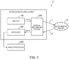
- FIG. 1 is a diagram showing a schematic overall configuration of a distance measuring device 1 according to an embodiment.
- the distance measuring device 1 generates a distance image of a measurement target object 10 using a scanning scheme or a TOF (Time Of Flight) scheme. More specifically, the distance measuring device 1 includes an emitter 100, an optical mechanism system 200, a measurer 300, and an image processor 400.
- the emitter 100 intermittently emits laser light L1.
- the optical mechanism system 200 irradiates the laser light L1 emitted by the emitter 100 on the measurement target object 10 and makes reflected light L2 of the laser light L1 reflected on the measurement target object 10 incident on the measurer 300.
- the laser light means light having an aligned phase and an aligned frequency.
- the measurer 300 measures the distance to the measurement target object 10 on the basis of the reflected light L2 received via the optical mechanism system 200. That is, the measurer 300 measures the distance to the measurement target object 10 on the basis of a time difference between a point in time when the emitter 100 irradiates the laser light L1 on the measurement target object 10 and a point in time when the reflected light L2 is measured.
- the image processor 400 performs removal of noise, distortion correction, and interpolation processing and outputs final distance image data on the basis of distances to a plurality of measurement points on the measurement target object 10.
- the image processor 400 may be incorporated in a housing of the distance measuring device 1.
- FIG. 2 is a diagram showing a configuration example of the distance measuring device 1 according to the first embodiment.
- the distance measuring device 1 includes the emitter 100, the optical mechanism system 200, the measurer 300, and the image processor 400.
- scattered lights L3 scattered light in a predetermined direction is referred to as reflected light L2.
- the emitter 100 includes a light source 11, an oscillator 11a, a first driving circuit 11b, a controller 16, and a second driving circuit 16a.
- the optical mechanism system 200 includes an irradiation optical system 202 and a light-receiving optical system 204.
- the irradiation optical system 202 includes a lens 12, a first optical element 13, a lens 13a, and a mirror (a reflection device) 15.
- the light-receiving optical system 204 incudes a second optical element 14 and the mirror 15. That is, the irradiation optical system 202 and the light-receiving optical system 204 share the mirror 15.
- the measurer 300 includes a photodetector 17, a sensor 18, a lens 18a, a first amplifier 19, a second amplifier 20, a time acquirer 21, and a distance measurer 22.
- rotating method there is a method of rotating the distance measuring device 1 to scan light
- OPA method Optical Phased Array
- This embodiment does not rely on a method of scanning light. Therefore, light may be scanned by the rotating method or the OPA method.
- the oscillator 11a of the emitter 100 generates a pulse signal on the basis of control by the controller 16.
- the first driving circuit 11b drives the light source 11 on the basis of the pulse signal generated by the oscillator 11a.
- the light source 11 is a laser light source such as a laser diode.
- the light source 11 intermittently emits the laser light L1 according to driving by the first driving circuit 11b.
- FIG. 3 is a diagram schematically showing an emission pattern of the light source 11.
- the horizontal axis indicates time and the vertical axis indicates emission timing of the light source 11.
- a figure on the lower side is a partially enlarged view in a figure on the upper side.
- the laser light L1 emitted n-th is represented as L1(n).
- "N" indicates the number of times of irradiation of the laser light L1(n) irradiated to measure the measurement target object 10.
- the light source 11, the lens 12, the first optical element 13, the second optical element 14, and the mirror 15 are disposed in this order on an optical axis O1 of the irradiation optical system 202. Consequently, the lens 12 ondenses the intermittently emitted laser light L1 and guides the laser light L1 to the first optical element 13.
- the first optical element 13 transmits the laser light L1 and makes a part of the laser light L1 incident on the photodetector 17 along an optical axis O3.
- the first optical element 13 is, for example, a beam splitter.
- the second optical element 14 further transmits the laser light L1 transmitted through the first optical element 13 and makes the laser light L1 incident on the mirror 15.
- the second optical element 14 is, for example, a half mirror.
- the mirror 15 includes a reflection surface 15a that reflects the laser light L1 intermittently emitted from the light source 11.
- the reflection surface 15a is capable of rotating around, for example, two rotation axes RA1 and RA2 crossing each other. Consequently, the mirror 15 cyclically changes an irradiation direction of the laser light L1.
- the controller 16 includes, for example, a CPU (Central Processing Unit) and a storage that stores a program and executes control by executing the program .
- the controller 16 performs, on the second driving circuit 16a, control for continuously changing an inclination angle of the reflection surface 15a.
- the second driving circuit 16a drives the mirror 15 according to a driving signal supplied from the controller 16. That is, the controller 16 controls the second driving circuit 16a to change the irradiation direction of the laser light L1.
- FIG. 4 is a schematic diagram enlarging and showing irradiation positions of the laser light L1 on the measurement target object 10.
- the reflection surface 15a changes the irradiation direction for each laser light L1 and discretely irradiates the laser light L1 along a substantially parallel plurality of linear paths P1 to Pm (m is a natural number equal to or larger than 2) on the measurement target object 10.
- the distance measuring device 1 irradiates the laser light L1(n) (0 ⁇ n ⁇ N) toward the measurement target object 10 once at a time while changing an irradiation direction O(n) (0 ⁇ n ⁇ N) of the laser light L1(n).
- the irradiation direction of the laser light L1(n) is represented as O(n). That is, in the distance measuring device 1 according to this embodiment, the laser light L1(n) is irradiated once in the irradiation direction O(n).
- the laser lights L1 having different irradiation directions are discretely irradiated on the linear paths P1 to Pm. Note that the number of linear paths and a scanning direction are not particularly limited.
- the reflection surface 15a of the mirror 15, the second optical element 14, the lens 18a, and the sensor 18 are disposed in the order of incidence of the reflected light L2.
- the optical axis O1 is a focal axis of the lens 12 that passes the center position of the lens 12.
- the optical axis O2 is a focal axis of the lens 18a that passes the center position of the lens 18a.
- the reflection surface 15a makes the reflected light L2 traveling along the optical axis O2 among the scattered lights L3 scattered on the measurement target object 10 incident on the second optical element 14.
- the second optical element 14 changes a traveling direction of the reflected light L2 reflected on the reflection surface 15a and makes the reflected light L2 incident on the lens 18a of the measurer 300 along the optical axis O2.
- the lens 18a ondenses the reflected light L2 made incident along the optical axis O2 to the sensor 18.
- a traveling direction of light reflected in a direction different from the direction of the laser light L1 among the scattered lights L3 deviates from the optical axis O2 of the light-receiving optical system 204. Therefore, even if the light reflected in the direction different from the direction of the optical axis O2 among the scattered lights L3 is made incident in the light-receiving optical system 204, the light is absorbed by a black body in a housing in which the light-receiving optical system 204 is disposed or is made incident on a position deviating from an incident surface of the sensor 18.
- environment lights such as sunlight scattered by some object, there are lights traveling along the optical axis O2. These lights are made incident on the incident surface of the sensor 18 at random and become random noise.
- optical paths of the laser light L1 and the reflected light L2 are separately shown for clarification. However, actually, the laser light L1 and the reflected light L2 overlap.
- An optical path in the center of a light beam of the laser light L1 is shown as the optical axis O1.
- optical path of the center of a light beam of the reflected light L2 is shown as the optical axis O2.
- the sensor 18 detects the reflected light L2 made incident from the lens 18a.
- the sensor 18 is composed of, for example, a silicon photomultiplier (SiPM).
- the silicon photomultiplier is a photocounting device obtained by converting an avalanche photo diode (APD) in a Geiger mode into multiple pixels.
- the silicon photomultiplier is capable of detecting feeble light in a photocounting level. That is, each of light receiving elements configuring the sensor 18 outputs an output signal corresponding to the intensity of light received via the optical mechanism system 200.
- the avalanche photodiode used in the Geiger mode is sometimes called SPAD (single-photon avalanche diode).
- the sensor 18 is composed of the silicon photomultiplier but is not limited to this.
- the sensor 18 may be configured by disposing a plurality of photodiodes, avalanche breakdown diodes (ABDs), or the like.
- the photodiode is composed of, for example, a semiconductor functioning as a photodetector.
- the avalanche diode is a diode that causes avalanche breakdown at a specific inverse voltage to thereby increase light reception sensitivity.
- the second amplifier 20 is, for example, a transimpedance amplifier.
- the second amplifier 20 amplifies an electric signal based on the reflected light L2.
- the second amplifier 20 amplifies and converts, for example, a current signal of the sensor 18 into a voltage signal serving as a measurement signal.
- the time acquirer 21 acquires a rising time in which a measurement signal obtained by converting reflected light of the laser beam L1 into a signal reaches a first threshold and a falling time in which the measurement signal reaches a second threshold after reaching the first threshold.
- the distance measurer 22 measures the distance to the measurement target object 10 on the basis of a time difference between timing based on a first time obtained by weighting the rising time acquired by the time acquirer 21 with a first weight coefficient and a second time obtained by weighting the falling time acquired by the time acquirer 21 with a second weight coefficient and irradiation timing of the laser beam L1.
- FIG. 5 is a block diagram showing a detailed configuration of the time acquirer 21 and the distance measurer 22.
- the time acquirer 21 includes a rising detector 21a, a first TDC 21b, a falling detector 21c, and a second TDC 21d.
- the distance measurer 22 includes a distance measurement processor 22a.
- the block diagram of FIG. 5 shows an example of signals. Order of the signals and wiring for the signals are not limited to order and wiring shown in FIG. 5 .
- FIG. 6 is a diagram showing an example of a rising time and a falling time of a measurement signal by the time detector 21.
- the horizontal axis of FIG. 6 indicates an elapsed time from light emission time of the laser beam L1.
- the vertical axis of FIG. 6 indicates a signal value of the measurement signal.
- Two kinds of signals having different values at peak timing TL2 of the measurement signal are shown.
- a rising time Tup in which the measurement signal reaches a first threshold Th1 and a falling time Tdn in which the measurement signal falls and reaches a second threshold Th2 after reaching the first threshold are respectively shown with respect to the two kinds of measurement signals.
- the rising detector 21a is, for example, a comparator.
- the rising detector 21a compares a signal value of a measurement signal output by the second amplifier 20 and the first threshold and outputs a rising signal at time when the signal value of the measurement signal exceeds the first threshold. That is, when the measurement signal reaches the first threshold according to the positive theory, the rising detector 21a outputs the rising signal.
- the first TDC 21b is, for example, a time to digital converter (TDC).
- TDC time to digital converter
- the first TDB 21b measures the rising time Tup from when the laser beam L1 is emitted until the rising detector 21a outputs the rising signal. That is, the first TDB 21b acquires the rising time Tup in which a measurement signal obtained by converting reflected light of the laser beam into a signal reaches the first threshold.
- the falling detector 21c is, for example, a comparator.
- the falling detector 21c compares the signal value of the measurement signal output by the second amplifier 20 and the second threshold and outputs a falling signal at time when the signal value of the measurement signal exceeds the second threshold. That is, when the measurement signal reaches the second threshold according to the negative theory, the falling detector 21c outputs the falling signal. For example, when the signal value of the measurement signal decreases and reaches the second threshold after reaching the first threshold, the falling detector 21c outputs the falling signal. That is, a time when the rising signal is output corresponds to a time when the measurement signal reaches the second threshold after reaching the first threshold after light emission time of the laser beam L1.
- the second TDC 21d is, for example, a time to digital converter (TDC).
- TDC time to digital converter
- the second TDC 21d measures the falling time Tdn from when the laser beam L1 is emitted until the falling detector 21c outputs the falling signal. That is, the second TDC 21d acquires the falling time Tdn in which the measurement signal obtained by converting the reflected light of the laser beam into a signal reaches the second threshold.
- the measurement signal may be negatively reversed and subjected to threshold processing.
- the rising detector 21a compares the signal value of the measurement signal output by the second amplifier 20 and the first threshold and outputs the rising signal when the signal value of the measurement signal changing in time series decreases as time elapses and exceeds the first threshold.
- the falling detector 21c compares the signal value of the measurement signal output by the second amplifier 20 and the second threshold and outputs the falling signal when the signal value of the measurement signal changing in time series increases as time elapses and exceeds the second threshold after reaching the first threshold.
- the distance measurer 22 includes, for example, an adder, a subtractor, a multiplier, and a divider.
- the distance measurer 22 measures the distance to a target object on the basis of the rising time Tup ( FIG. 6 ) and the falling time Tdn ( FIG. 6 ) acquired by the time acquirer 21. That is, the distance measurement processor 22a measures the distance to the target object on the basis of a time difference between timing based on a first time obtained by weighting the rising time Tup ( FIG. 6 ) with a first weight coefficient W1 and a second time obtained by weighting the falling time Tdn ( FIG. 6 ) with a second weight coefficient W2 and irradiation timing of the laser beam.
- Each of the time acquirer 21 and the distance measurer 22 is composed of hardware.
- each of the time acquirer 21 and the distance measurer 22 is composed of a circuit.
- the second threshold Th2 according to this embodiment is set to the same value as the first threshold Th1 in order to simplify calculation of a weight coefficient.
- the second threshold Th2 is not limited to this.
- FIG. 7 is a diagram schematically showing a state in which a measurement signal of the sensor 18 ( FIG. 1 ) piles up.
- the horizontal axis indicates an elapsed time from light emission time of the laser beam L1.
- the vertical axis indicates a signal value of the measurement signal. Two kinds of signals having different peak values of the measurement signal are shown.
- the sensor 18 ( FIG. 1 ) according to this embodiment is composed of an SPAD cell.
- a relation between the number of received photons per unit time and an output value of the SPAD cell has a linear characteristic when the number of received photons per unit time is small.
- the output value of the SPAD cell is saturated.
- the relation between the number of received photons per unit time and the output value of the SPAD cell has a nonlinear characteristic. Therefore, as shown in FIG. 7 , a peak of the measurement signal sometimes becomes gentle. This is called pile-up.
- FIGS. 8 to 11 are diagrams for explaining a simulation example of the timing TL3 at the time when the measurement signal piles up. It is explained below that, even if the measurement signal piles up, the timing TL3 based on the first time obtained by weighting the rising time Tup with the first weight coefficient W1 and the second time obtained by weighting the falling time Tdn with the second weight coefficient W2 indicates a value substantially equal to a value at the peak timing TL2 ( FIG. 6 ).
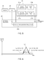
- FIG. 8 is a diagram for explaining a temporal relation between an emission point in time of the light source 11 and conversion into an electric signal by the sensor 18.
- the horizontal axis indicates time.
- P10 indicates an example of an irradiation time of laser pulse light irradiated by the light source 11.
- 10 ns indicates a pulse width.
- P12 indicates a time range in which the laser pulse light irradiated at P10 is reflected and returns from the measurement target object 10 present 10 meters ahead. That is, since round-trip speed of light is 6.7 ns/m, when the distance to the measurement target object 10 is 10 m, the time range is 67 ns.
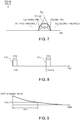
- FIG. 9 is a diagram showing an output waveform example during one photon detection of the SPAD cell.
- I(t) When an output waveform is represented as I(t), the output waveform I(t) is approximately indicated by Expression (2).
- An output time constant of the SPAD cell is set to 10 ns.
- FIG. 10 is a diagram showing a simulation example of a measurement signal value of the SPAD cell at the time when the pile-up is not considered.
- the vertical axis indicates a measurement signal value.
- the horizontal axis indicates time "t”.
- a PDE the number of detected photons/the number of input photons
- the number of SPAD cells per one pixel is set to 10.
- the output waveform I(t) indicated by Expression (2) is used. Under this condition, as the number of excited photons before pile-up, for example, during input of ten photons, one photon can be detected in average.
- FIG. 10 a simulation is performed with the number of photons per unit time, that is, photons/input time set to 10.0, 14.4, 20.7, 29.8, 42.8, 61.6, 88.6, 127.4, 183.3, 263.7, 379.3, 545.6, 784.8, 1128.8, 1623.8, 2335.7, 3359.8, 4832.9, 6951.9, and 10000.0.
- Environment light is set to 0.
- An output band of the second amplifier 20 ( FIG. 1 ) is set to 100 MHZ.
- the vertical axis indicates time.
- the horizontal axis indicates the number of excited photons before pile-up.
- a first line 130a indicates the rising time Tup.
- a second line 130b indicates the falling time Tdn.
- a third line 130c indicates the timing TL3.
- the rising time Tup and the falling time Tdn fluctuate according to the number of excited photons before pile-up.
- the first weight coefficient W1 in advance for the sensor 18 having different characteristics as well.
- the sensor 18 according to this embodiment is composed of a silicon photomultiplier tube but is not limited to this.
- the first weight coefficient W1 can be calculated for other types of imaging elements.
- FIG. 12 is a diagram showing input and output characteristics of the second amplifier 20.
- the vertical axis indicates an output signal value.
- the horizontal axis indicates an input signal value.
- An input and output characteristic 140a is linear and indicates an ideal input and output characteristic.
- An input and output characteristic 140b is nonlinear and indicates an input and output characteristic with distortion.
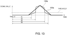
- FIG. 13 is a diagram showing a signal value based on the ideal input and output characteristic and a signal value based on the input and output characteristic with distortion.
- the vertical axis indicates a signal value.
- the horizontal axis indicates time.
- a signal value 150a is a signal value obtained when the second amplifier 20 having the ideal input and output characteristic is used.
- a signal value 150b is a signal value obtained when the second amplifier 20 having the input and output characteristic with distortion is used.
- a measurement distance by the signal value 150a is (0.5*T1+0.5*T4)/6.7.
- a measurement distance by the signal value 150b is (0.5*T2+0.5*T3)/6.7.
- the current signal is converted into the measurement signal by the second amplifier 20.
- the conversion of the current signal into the measurement signal is not limited to this.
- the current signal may be converted into the measurement signal by the second amplifier 20 and an AD converter or the like. In this case, it is possible to prevent deterioration in measurement accuracy even if the AD converter has the input and output characteristic with distortion.
- FIG. 14 is a diagram showing a measurement method for a CFD as a comparative example.
- the CFD constant fraction discriminator
- the CFC reverses and delays the measurement signals 70a and 72a to acquire signals 70c and 72c.
- the CFD acquires signals 70d and 72d obtained by adding the reversed and delayed signals 70c and 72c to the attenuation signals 70b and 72b.
- the CFD uses zero-cross points of the signals 70d and 72d as reference times of distance measurement. As shown in FIG. 14 , when saturation and pile-up do not occur, the influence of peak values of the measurement signals 70a and 72a can be prevented.
- the reference time of the distance measurement is acquired on the basis of the rising time Tup in which the measurement signal reaches the first threshold and the falling time Tdn in which the measurement signal falls and reaches the second threshold after reaching the first threshold. Therefore, it is possible to prevent the influence on measurement accuracy even if saturation or pile-up occurs in the measurement signals 70a and 72a.
- the distance to the target object is measured on the basis of the rising time Tup in which the measurement signal reaches the first threshold and the falling time Tdn in which the measurement signa falls and reaches the second threshold after reaching the first threshold. Consequently, it is possible to reduce the influence of a measurement signal having a value equal to or larger than the first threshold on the distance measurement. It is possible to accurately and stably measure the distance to the target object even if the measurement signal, for example, piles up or is saturated.
- a measurement distance is more highly accurately acquired by acquiring a weight coefficient referring to at least one of an intensity value of a measurement signal and an intensity value of environment light.
- FIG. 15 is a block diagram showing a detailed configuration example of the distance measurer 22 according to the second embodiment.
- the distance measurer 22 includes a signal light intensity detector 22b, an environment light intensity detector 22c, and a weight coefficient acquirer 22d.
- Each of the signal light intensity detector 22b, the environment light intensity detector 22c, and the weight coefficient acquirer 22d is composed of hardware.
- each of the signal light intensity detector 22b, the environment light intensity detector 22c, and the weight coefficient acquirer 22d is composed of a circuit.
- the block diagram of FIG. 15 shows an example of signals. Order of the signals and wiring for the signals are not limited to order and wiring shown in FIG. 15 .
- the signal light intensity detector 22b acquires, for example, a maximum value as a first representative value of a measurement signal in a time T from when the light source 11 ( FIG. 1 ) irradiates a laser beam L1(n) until the light source 11 irradiates the next laser beam L1(n+1).
- the signal light intensity detector 22b may acquire a maximum value of a signal value after reducing noise with filtering processing.
- the environment light intensity detector 22c detects the intensity of environment light. More specifically, the environment light intensity detector 22c acquires, for example, an average value as a second representative value of the measurement signal in the time T in a period in which the light source 11 ( FIG. 1 ) stops irradiation of a laser beam.
- the environment light intensity detector 22c may acquire a representative value after reducing noise with filtering processing.
- the second representative value may be a maximum value, an intermediate value, or the like of the measurement signal in the time T.
- the weight coefficient acquirer 22d acquires the weight coefficients W1 and W2 on the basis of at least one of the first representative value detected by the signal light intensity detector 22b and the second representative value detected by the environment light intensity detector 22c.
- the weight coefficient acquirer 22d is explained more in detail with reference to FIGS. 16 to 20 .
- FIG. 16 is a diagram showing a maximum value of a measurement signal value obtained by changing the number of photons per unit time shown in FIG. 10 .
- the vertical axis indicates the maximum value of the measurement signal value.
- the horizontal axis indicates the number of photons per unit time, that is, photons/input time.
- the maximum value of the measurement signal value corresponds to the number of photons per unit time.
- the maximum value has a tendency that the maximum value monotonously increases as the number of photons per unit time increases and an increase rate decreases as the number of photons increases.
- FIG. 17 is a diagram of the first weight coefficient W1 calculated for each measurement signal value corresponding to the maximum value shown in FIG. 16 .
- the vertical axis indicates the first weight coefficient W1.
- the horizontal axis indicates the maximum value of the measurement signal value shown in FIG. 16 .
- the weight coefficient W1 with which the timing TL3 and the peak timing TL2 of the measurement signal shown in FIG. 12 coincide most is calculated.
- the maximum value of the measurement signal value corresponds to the number of photons per unit time. Therefore, the weight coefficient W1 with which the timing TL3 and the peak timing TL2 of the measurement signal coincide mode can be obtained for each maximum value of the measurement signal value.
- the first weighting factor W 1 monotonously decreases as the maximum value of the measured signal value increases and the first weighting factor W 1 increases monotonically with the predetermined value as the boundary as the maximum value of the measured signal value increases. In this way, the first weighting coefficient W 1 monotonically increases as the maximum value of the measured signal value increases when the maximum value of the measured signal value is equal to or larger than the predetermined value.
- the weight coefficient acquirer 22d has stored therein, as a lookup table, for example, a relation between the maximum value and the first weight coefficient W1 shown in FIG. 17 . Consequently, the weight coefficient acquirer 22d acquires the first weight coefficient W1 using, as an argument, the first representative value, that is, the maximum value detected by the signal light intensity detector 22b. In this way, the weight coefficient acquirer 22d acquires the first weight coefficient W1 on the basis of the first representative value, that is, the maximum value detected by the signal light intensity detector 22b. Therefore, the weight coefficient acquirer 22d can obtain the first weight coefficient W1 that is more highly accurately calculated. Consequently, the distance measurement processor 22a is capable of substituting the first weight coefficient W1 acquired by the weight coefficient acquirer 22d in Expression (1) described above and more highly accurately measuring the distance to the measurement target object 10.
- FIG. 18 is a diagram of the first weight coefficient W1 corresponding to the maximum value of the measurement signal calculated by changing an intensity value of environment light.
- the vertical axis indicates the first weight coefficient W1.
- the horizontal axis indicates the maximum value of the measurement signal value.
- the environment light is photons steadily made incident on the sensor 18 ( FIG. 1 ). Therefore, the environment light excites an electric signal in a DC (direct current) manner. That is, as the environment light increases, an effect equivalent to the effect achieved when the number of SPADs is reduced is generated in average. Therefore, in FIG. 18 , the intensity of the environment light is indicated as a percentage of a reduction of the number of SPADs. For example, 10% is equivalent to a reduction of 10% of the number of SPADs.
- the weight coefficient acquirer 22d increases an increase rate of the first weight coefficient respect to an increase of a maximum value of the measured signal value as the intensity value of the environment light increases when the maximum value of the measurement signal is equal to or larger than a predetermined value.
- the weight coefficient acquirer 22d has stored therein, as a lookup table, for example, a relation between the maximum value and the intensity value of the environment light and the first weight coefficient W1 shown in FIG. 18 . Consequently, the weight coefficient acquirer 22d acquires the first weight coefficient W1 using, as arguments, the first representative value, that is, the maximum value detected by the signal light intensity detector 22b and the second representative value, that is, the average value of the measurement signal by the environment light detected by the environment light intensity detector 22c.
- FIG. 18 is a diagram of the first weight coefficient W1 corresponding to the maximum value of the measurement signal calculated by changing an intensity value of environment light. Signal intensity by the environment light can be considered as a DC component of a measurement signal value.
- FIG. 19 is a diagram of the first weight coefficient W1 corresponding to a corrected maximum value of a measurement signal calculated by changing the intensity value of the environment light W1.
- the vertical axis indicates the first weight coefficient W1.
- the horizontal axis indicates a corrected maximum value of the measurement signal value.
- a maximum value Ma is the first representative value detected by the signal light intensity detector 22b.
- An intensity value ES of the environment light is the second representative value detected by the environment light intensity detector 22c.
- An approximate line 200a indicates an approximate line of the first weight coefficient W1 with respect to the corrected maximum value CMa.
- the weight coefficient acquirer 22d has stored therein, as a lookup table, the approximate line 200a of the first weight coefficient W1 with respect to the corrected maximum value CMa.
- the weight coefficient acquirer 22d has stored therein, as a linear equation, the approximate line 200a of the first weight coefficient W1 with respect to the corrected maximum value CMa.
- the linear equation is a general primary regression equation. Therefore, description of the linear equation is omitted.
- the approximate line 200a is stored as the lookup table. Therefore, a memory amount can be further reduced than when a lookup table is stored for each intensity value of the environment light.
- the memory amount can be further reduced than when the lookup table is stored.
- the weight coefficient acquirer 22d adds 1 to the intensity value ES of the environment light, which is the second representative value, detected by the environment light intensity detector 22c, multiplies the maximum value Ma, which is the first representative value, detected by the signal light intensity detector 22b, and acquires the corrected maximum value CMa.
- the weight coefficient acquirer 22d acquires the first weight coefficient W1 corresponding to the corrected maximum value CMa.
- the corrected maximum value CMa is small, accuracy is low. However, in that case, the distance to the measurement target object 10 is considered to be long. Very high accuracy is considered to be unnecessary.
- the distance measurement processor 22a changes the first weight coefficient W1 according to the signal intensity of the measurement signal and the environment light intensity. Consequently, the measurement distance to the measurement target object 10 can be more highly accurately acquired.
- the first weight coefficient W1 used for weighting the rising time Tup and the falling time Tdn is acquired with reference to at least one of the intensity value of the measurement signal and the intensity value of the environment light. Consequently, even if the input and output characteristic of the sensor 18 changes according to the intensity value of the measurement signal and the intensity value of the environment light, it is possible to acquire the first weight coefficient W1 corresponding to the input and output characteristic. Even if the intensity value of the measurement signal and the intensity value of the environment light change, it is possible to accurately and stably measure the distance to a target object.
- a measurement distance is more highly accurately acquired by changing the first weight coefficient according to a pulse width of a measurement signal.
- FIG. 20 is a block diagram showing a detailed configuration example of the distance measurer 22 according to the third embodiment. As shown in FIG. 20 , the distance measurer 22 further includes a pulse width acquirer 22e. The pulse width acquirer 22e is composed of a circuit.
- the block diagram of FIG. 20 shows an example of signals. Order of the signals and wiring for the signals are not limited to order and wiring shown in FIG. 20 .
- the pulse width acquirer 22e acquires a pulse width on the basis of the rising time Tup detected by the rising detector 21a and the falling time Tdn detected by the falling detector 21c. For example, the pulse width acquirer 22e acquires a difference between the falling time Tdn and the rising time Tup as the pulse width.
- the falling detector 21c according to this embodiment is configured to output an error signal including information indicating a detection error when the falling detector 21c cannot detect the falling time Tdn even if the irradiation interval T of the light source 11 ( FIG. 1 ) is exceeded.
- FIG. 21 is a conceptual diagram for explaining characteristics of a measurement signal according to pulse widths.
- the vertical axis indicates a measurement signal value.
- the horizontal axis indicates time.
- the pulse widths increase in the order of A, B, C, and D.
- the number of photons per unit time is the smallest.
- B the number of photons per unit time is larger than the number of photons in A and the measurement signal piles up.
- the number of photons per unit time is larger than the number of photons in B and a time constant of falling changes from the time constant in B.
- D the number of photons per unit time is larger than the number of photons in C and the falling detector 21c cannot detect the falling time Tdn. In this way, the characteristics of the measurement signal change according to the pulse widths.
- the distance measurement processor 22a changes an acquisition method for the first weight coefficient W1 on the basis of the pulse width acquired by the pulse width acquirer 22e. More specifically, when the pulse width corresponds to A, the distance measurement processor 22a integrates, for several laser irradiation, measurement signals output by the time division processor 21 and measures the distance to the measurement target object 10 on the basis of a peak value of an integrated signal. When the pulse width corresponds to B, the distance measurement processor 22a measures the distance to the measurement target object 10 on the basis of Expression (1) as explained above.
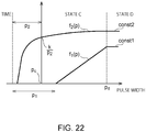
- FIG. 22 is a diagram for explaining characteristics of functions used in arithmetic expressions corresponding to C and D.
- the vertical axis indicates a value of a function.
- the horizontal axis indicates a pulse width P.
- the distance measurement processor 22a acquires a measurement distance according to, for example, Expression (4).
- Expression (4) (1-k) is represented as W1.
- Expression (4) is an expression equivalent to Expression (1) excluding k ⁇ P1, which is an offset component.
- the distance measurement processor 22a acquires a measurement distance according to, for example, Expression (5).
- Measurement distance light speed ⁇ Tup + CONST 1 / 2
- the distance measurement processor 22a acquires a measurement distance according to, for example, Expression (6).
- the weight of the rising time Tup becomes larger than the weight of the falling time Tdn as the pulse width P increases.
- Measurement distance light speed ⁇ Tup + f 2 P ⁇ Tdn / 2
- f2(P) is treated as CONST2.
- the rising time Tup is steep and the falling time Tdn is gentle.
- the rising time Tup has small input light amount dependency.
- the falling time Tdn has large input light amount dependency.
- the distance measurement processor 22a In the state of D in which the pulse width is in a range of the pulse width Pd or more, the falling time Tdn sometimes cannot be acquired. However, in the state of D, the distance measurement processor 22a according to this embodiment does not use the falling time Tdn. Therefore, it is possible to measure a measurement distance. By introducing the pulse width P into the distance measurement in this way, a degree of freedom further increases and fitting accuracy of a measurement signal is further improved.
- the weight of the rising time Tup is set larger than the weight of the falling time Tdn as the pulse width P increases.
- the rising time Tup has small input light amount dependency and the falling time Tdn has large input light amount dependency. Therefore, even if the input light amount dependency is reduced and the intensity value of the measurement signal further increases, it is possible to accurately and stably measure the distance to the target object.
Landscapes
- Engineering & Computer Science (AREA)
- Physics & Mathematics (AREA)
- Computer Networks & Wireless Communication (AREA)
- General Physics & Mathematics (AREA)
- Radar, Positioning & Navigation (AREA)
- Remote Sensing (AREA)
- Electromagnetism (AREA)
- Optical Radar Systems And Details Thereof (AREA)
- Measurement Of Optical Distance (AREA)
Applications Claiming Priority (1)
| Application Number | Priority Date | Filing Date | Title |
|---|---|---|---|
| JP2018173543A JP6990158B2 (ja) | 2018-09-18 | 2018-09-18 | 距離計測装置、及び距離計測方法 |
Publications (1)
| Publication Number | Publication Date |
|---|---|
| EP3627177A1 true EP3627177A1 (en) | 2020-03-25 |
Family
ID=65729195
Family Applications (1)
| Application Number | Title | Priority Date | Filing Date |
|---|---|---|---|
| EP19161583.0A Pending EP3627177A1 (en) | 2018-09-18 | 2019-03-08 | Distance measuring device and distance measuring method |
Country Status (4)
| Country | Link |
|---|---|
| US (1) | US11391824B2 (ja) |
| EP (1) | EP3627177A1 (ja) |
| JP (1) | JP6990158B2 (ja) |
| CN (1) | CN110907942B (ja) |
Families Citing this family (6)
| Publication number | Priority date | Publication date | Assignee | Title |
|---|---|---|---|---|
| JP7317530B2 (ja) | 2019-03-14 | 2023-07-31 | 株式会社東芝 | 距離計測装置、距離計測方法、及び信号処理方法 |
| CN111708242B (zh) * | 2020-05-20 | 2023-04-18 | 维沃移动通信有限公司 | 光学距离传感器、信号处理电路、方法及电子设备 |
| CN111596302A (zh) * | 2020-05-21 | 2020-08-28 | 深圳市灵明光子科技有限公司 | 一种基于SiPM信号时序点的测距方法及装置 |
| CN111580121B (zh) * | 2020-05-21 | 2021-11-26 | 深圳市灵明光子科技有限公司 | 一种基于SiPM信号摆幅的测距方法及装置 |
| JP7425702B2 (ja) * | 2020-09-17 | 2024-01-31 | 株式会社東芝 | 距離計測装置、及び距離計測方法 |
| CN112305519B (zh) * | 2020-10-19 | 2022-05-13 | 南京理工大学 | 基于硅光电倍增管的激光雷达快速探测系统 |
Citations (5)
| Publication number | Priority date | Publication date | Assignee | Title |
|---|---|---|---|---|
| EP0782007A2 (en) * | 1995-12-27 | 1997-07-02 | Denso Corporation | Method and apparatus for measuring distance |
| US20030103197A1 (en) * | 2001-12-04 | 2003-06-05 | Noriaki Shirai | Method and apparatus for measuring distance to a detection object |
| US20050146705A1 (en) * | 2003-12-24 | 2005-07-07 | Lei Jonathan S. | Range accuracy compensation circuit for single-shot laser rangefinders |
| US20120194798A1 (en) * | 2011-01-28 | 2012-08-02 | Analog Modules Inc. | Accuracy of a laser rangefinder receiver |
| CN108513618A (zh) * | 2017-03-29 | 2018-09-07 | 深圳市大疆创新科技有限公司 | 脉冲信息测量方法及相关装置、移动平台 |
Family Cites Families (18)
| Publication number | Priority date | Publication date | Assignee | Title |
|---|---|---|---|---|
| JP3249003B2 (ja) | 1993-12-27 | 2002-01-21 | マツダ株式会社 | 距離計測装置 |
| DE102004031024C5 (de) * | 2004-06-26 | 2011-04-28 | Leuze Lumiflex Gmbh + Co. Kg | Optischer Sensor |
| JP2005331526A (ja) | 2005-08-24 | 2005-12-02 | Denso Corp | 距離測定装置 |
| JP4116052B2 (ja) * | 2006-09-14 | 2008-07-09 | 北陽電機株式会社 | 測距装置 |
| DE102007051979A1 (de) * | 2007-10-31 | 2009-05-07 | Leuze Electronic Gmbh & Co Kg | Sensor |
| DE102009024464B4 (de) * | 2009-06-10 | 2017-09-21 | Carl Zeiss Ag | Auswerteeinrichtung, Messanordnung und Verfahren zur Weglängenmessung |
| JP2013096742A (ja) * | 2011-10-28 | 2013-05-20 | Denso Corp | レーダ装置 |
| JP6225411B2 (ja) | 2012-10-16 | 2017-11-08 | 株式会社豊田中央研究所 | 光学的測距装置 |
| JP6045963B2 (ja) * | 2013-04-05 | 2016-12-14 | 日立マクセル株式会社 | 光測距装置 |
| EP3088914B1 (en) | 2013-12-27 | 2020-05-06 | Ricoh Company, Ltd. | Distance measuring apparatus, electronic apparatus, distance measuring method, and distance measuring program |
| JP2016014535A (ja) | 2014-06-30 | 2016-01-28 | 日本信号株式会社 | 測距装置 |
| JP6477083B2 (ja) | 2015-03-19 | 2019-03-06 | 株式会社豊田中央研究所 | 光学的測距装置 |
| US10739456B2 (en) | 2016-06-17 | 2020-08-11 | Kabushiki Kaisha Toshiba | Distance measuring device |
| CN106019300A (zh) * | 2016-08-05 | 2016-10-12 | 上海思岚科技有限公司 | 一种激光测距装置及其激光测距方法 |
| JP2018054426A (ja) | 2016-09-28 | 2018-04-05 | パイオニア株式会社 | 情報処理装置、光学機器、制御方法、プログラム及び記憶媒体 |
| JP6845774B2 (ja) | 2017-09-15 | 2021-03-24 | 株式会社東芝 | 距離計測装置 |
| US11157113B2 (en) * | 2018-04-13 | 2021-10-26 | Apple Inc. | Self-mixing interference based sensors for characterizing touch input |
| JP7379021B2 (ja) * | 2019-08-29 | 2023-11-14 | 株式会社東芝 | 距離計測装置、距離計測方法、及び速度計測装置 |
-
2018
- 2018-09-18 JP JP2018173543A patent/JP6990158B2/ja active Active
-
2019
- 2019-01-10 CN CN201910021293.4A patent/CN110907942B/zh active Active
- 2019-03-08 EP EP19161583.0A patent/EP3627177A1/en active Pending
- 2019-03-11 US US16/297,783 patent/US11391824B2/en active Active
Patent Citations (5)
| Publication number | Priority date | Publication date | Assignee | Title |
|---|---|---|---|---|
| EP0782007A2 (en) * | 1995-12-27 | 1997-07-02 | Denso Corporation | Method and apparatus for measuring distance |
| US20030103197A1 (en) * | 2001-12-04 | 2003-06-05 | Noriaki Shirai | Method and apparatus for measuring distance to a detection object |
| US20050146705A1 (en) * | 2003-12-24 | 2005-07-07 | Lei Jonathan S. | Range accuracy compensation circuit for single-shot laser rangefinders |
| US20120194798A1 (en) * | 2011-01-28 | 2012-08-02 | Analog Modules Inc. | Accuracy of a laser rangefinder receiver |
| CN108513618A (zh) * | 2017-03-29 | 2018-09-07 | 深圳市大疆创新科技有限公司 | 脉冲信息测量方法及相关装置、移动平台 |
Non-Patent Citations (1)
| Title |
|---|
| KURTTI S ET AL: "A Wide Dynamic Range CMOS Laser Radar Receiver With a Time-Domain Walk Error Compensation Scheme", IEEE TRANSACTIONS ON CIRCUITS AND SYSTEMS I: REGULAR PAPERS, IEEE, US, vol. 64, no. 3, 1 March 2017 (2017-03-01), pages 550 - 561, XP011641888, ISSN: 1549-8328, [retrieved on 20170223], DOI: 10.1109/TCSI.2016.2619762 * |
Also Published As
| Publication number | Publication date |
|---|---|
| JP2020046247A (ja) | 2020-03-26 |
| CN110907942A (zh) | 2020-03-24 |
| CN110907942B (zh) | 2024-04-16 |
| JP6990158B2 (ja) | 2022-01-12 |
| US11391824B2 (en) | 2022-07-19 |
| US20200088853A1 (en) | 2020-03-19 |
Similar Documents
| Publication | Publication Date | Title |
|---|---|---|
| EP3627177A1 (en) | Distance measuring device and distance measuring method | |
| EP3268771B1 (en) | Coherent ladar using intra-pixel quadrature detection | |
| CN107085218B (zh) | 确定返回光脉冲的返回时间的方法以及spl扫描仪 | |
| EP3457170B1 (en) | Distance measuring device | |
| JP6225411B2 (ja) | 光学的測距装置 | |
| US8355117B2 (en) | Method and arrangement for measuring the distance to an object | |
| US10698108B2 (en) | Receive signal beam steering and detector for an optical distance measurement system | |
| KR20190057125A (ko) | 이미징 어레이 내의 픽셀의 노출 값으로부터 백그라운드 광을 차감하기 위한 방법 및 이를 이용한 픽셀 | |
| KR101145132B1 (ko) | 3차원 영상화 펄스 레이저 레이더 시스템 및 이 시스템에서의 자동 촛점 방법 | |
| WO2020166609A1 (ja) | 光学的測距装置 | |
| JP2022190043A (ja) | 電子装置及び距離計測方法 | |
| KR102226359B1 (ko) | 스캔 모드를 변경하는 3차원 스캐닝 라이다 센서 | |
| US20210074743A1 (en) | Light detection apparatus and electronic device | |
| US20200300978A1 (en) | Dynamic range improvements in lidar applications | |
| JP2017203708A (ja) | 光測距装置 | |
| US20210088661A1 (en) | Photodetector and optical ranging apparatus using the same | |
| CN115190979A (zh) | 用于光探测和测距的系统和方法 | |
| Bronzi et al. | 3D sensor for indirect ranging with pulsed laser source | |
| US20210003678A1 (en) | Electronic device, light receiving device, light projecting device, and distance measurement method | |
| US20230204727A1 (en) | Distance measurement device and distance measurement method | |
| Huntington et al. | 512-element linear InGaAs APD array sensor for scanned time-of-flight lidar at 1550 nm | |
| WO2013076769A1 (ja) | 光測距装置 | |
| Yamamoto | Photonic Technology Improvements that Drives Future of LiDAR Applications | |
| JP2020176956A (ja) | 距離計測装置および距離計測方法 |
Legal Events
| Date | Code | Title | Description |
|---|---|---|---|
| PUAI | Public reference made under article 153(3) epc to a published international application that has entered the european phase |
Free format text: ORIGINAL CODE: 0009012 |
|
| STAA | Information on the status of an ep patent application or granted ep patent |
Free format text: STATUS: REQUEST FOR EXAMINATION WAS MADE |
|
| 17P | Request for examination filed |
Effective date: 20190308 |
|
| AK | Designated contracting states |
Kind code of ref document: A1 Designated state(s): AL AT BE BG CH CY CZ DE DK EE ES FI FR GB GR HR HU IE IS IT LI LT LU LV MC MK MT NL NO PL PT RO RS SE SI SK SM TR |
|
| AX | Request for extension of the european patent |
Extension state: BA ME |
|
| STAA | Information on the status of an ep patent application or granted ep patent |
Free format text: STATUS: EXAMINATION IS IN PROGRESS |
|
| 17Q | First examination report despatched |
Effective date: 20211011 |
|
| 17Q | First examination report despatched |
Effective date: 20211022 |