EP3627017B1 - Ensemble de boîte de disjoncteurs - Google Patents
Ensemble de boîte de disjoncteurs Download PDFInfo
- Publication number
- EP3627017B1 EP3627017B1 EP19195490.8A EP19195490A EP3627017B1 EP 3627017 B1 EP3627017 B1 EP 3627017B1 EP 19195490 A EP19195490 A EP 19195490A EP 3627017 B1 EP3627017 B1 EP 3627017B1
- Authority
- EP
- European Patent Office
- Prior art keywords
- breaker
- assembly
- valve
- outlet
- box assembly
- Prior art date
- Legal status (The legal status is an assumption and is not a legal conclusion. Google has not performed a legal analysis and makes no representation as to the accuracy of the status listed.)
- Active
Links
- 239000012530 fluid Substances 0.000 claims description 59
- 238000004891 communication Methods 0.000 claims description 21
- VNWKTOKETHGBQD-UHFFFAOYSA-N methane Chemical compound C VNWKTOKETHGBQD-UHFFFAOYSA-N 0.000 claims description 14
- 239000003345 natural gas Substances 0.000 claims description 7
- 238000011144 upstream manufacturing Methods 0.000 claims description 7
- 238000007789 sealing Methods 0.000 claims description 6
- 239000007789 gas Substances 0.000 description 14
- 238000000034 method Methods 0.000 description 4
- XLYOFNOQVPJJNP-UHFFFAOYSA-N water Substances O XLYOFNOQVPJJNP-UHFFFAOYSA-N 0.000 description 3
- 230000000712 assembly Effects 0.000 description 1
- 238000000429 assembly Methods 0.000 description 1
- 230000008878 coupling Effects 0.000 description 1
- 238000010168 coupling process Methods 0.000 description 1
- 238000005859 coupling reaction Methods 0.000 description 1
- 230000001419 dependent effect Effects 0.000 description 1
- 238000001514 detection method Methods 0.000 description 1
- 238000005516 engineering process Methods 0.000 description 1
- 239000000446 fuel Substances 0.000 description 1
- 239000007769 metal material Substances 0.000 description 1
- 238000012986 modification Methods 0.000 description 1
- 230000004048 modification Effects 0.000 description 1
Images


Classifications
-
- F—MECHANICAL ENGINEERING; LIGHTING; HEATING; WEAPONS; BLASTING
- F23—COMBUSTION APPARATUS; COMBUSTION PROCESSES
- F23N—REGULATING OR CONTROLLING COMBUSTION
- F23N5/00—Systems for controlling combustion
- F23N5/24—Preventing development of abnormal or undesired conditions, i.e. safety arrangements
- F23N5/245—Preventing development of abnormal or undesired conditions, i.e. safety arrangements using electrical or electromechanical means
-
- F—MECHANICAL ENGINEERING; LIGHTING; HEATING; WEAPONS; BLASTING
- F16—ENGINEERING ELEMENTS AND UNITS; GENERAL MEASURES FOR PRODUCING AND MAINTAINING EFFECTIVE FUNCTIONING OF MACHINES OR INSTALLATIONS; THERMAL INSULATION IN GENERAL
- F16K—VALVES; TAPS; COCKS; ACTUATING-FLOATS; DEVICES FOR VENTING OR AERATING
- F16K17/00—Safety valves; Equalising valves, e.g. pressure relief valves
- F16K17/20—Excess-flow valves
- F16K17/22—Excess-flow valves actuated by the difference of pressure between two places in the flow line
- F16K17/24—Excess-flow valves actuated by the difference of pressure between two places in the flow line acting directly on the cutting-off member
- F16K17/28—Excess-flow valves actuated by the difference of pressure between two places in the flow line acting directly on the cutting-off member operating in one direction only
-
- F—MECHANICAL ENGINEERING; LIGHTING; HEATING; WEAPONS; BLASTING
- F16—ENGINEERING ELEMENTS AND UNITS; GENERAL MEASURES FOR PRODUCING AND MAINTAINING EFFECTIVE FUNCTIONING OF MACHINES OR INSTALLATIONS; THERMAL INSULATION IN GENERAL
- F16K—VALVES; TAPS; COCKS; ACTUATING-FLOATS; DEVICES FOR VENTING OR AERATING
- F16K11/00—Multiple-way valves, e.g. mixing valves; Pipe fittings incorporating such valves
- F16K11/10—Multiple-way valves, e.g. mixing valves; Pipe fittings incorporating such valves with two or more closure members not moving as a unit
- F16K11/20—Multiple-way valves, e.g. mixing valves; Pipe fittings incorporating such valves with two or more closure members not moving as a unit operated by separate actuating members
- F16K11/22—Multiple-way valves, e.g. mixing valves; Pipe fittings incorporating such valves with two or more closure members not moving as a unit operated by separate actuating members with an actuating member for each valve, e.g. interconnected to form multiple-way valves
-
- F—MECHANICAL ENGINEERING; LIGHTING; HEATING; WEAPONS; BLASTING
- F16—ENGINEERING ELEMENTS AND UNITS; GENERAL MEASURES FOR PRODUCING AND MAINTAINING EFFECTIVE FUNCTIONING OF MACHINES OR INSTALLATIONS; THERMAL INSULATION IN GENERAL
- F16K—VALVES; TAPS; COCKS; ACTUATING-FLOATS; DEVICES FOR VENTING OR AERATING
- F16K17/00—Safety valves; Equalising valves, e.g. pressure relief valves
- F16K17/20—Excess-flow valves
- F16K17/34—Excess-flow valves in which the flow-energy of the flowing medium actuates the closing mechanism
-
- F—MECHANICAL ENGINEERING; LIGHTING; HEATING; WEAPONS; BLASTING
- F16—ENGINEERING ELEMENTS AND UNITS; GENERAL MEASURES FOR PRODUCING AND MAINTAINING EFFECTIVE FUNCTIONING OF MACHINES OR INSTALLATIONS; THERMAL INSULATION IN GENERAL
- F16K—VALVES; TAPS; COCKS; ACTUATING-FLOATS; DEVICES FOR VENTING OR AERATING
- F16K27/00—Construction of housing; Use of materials therefor
- F16K27/003—Housing formed from a plurality of the same valve elements
-
- F—MECHANICAL ENGINEERING; LIGHTING; HEATING; WEAPONS; BLASTING
- F16—ENGINEERING ELEMENTS AND UNITS; GENERAL MEASURES FOR PRODUCING AND MAINTAINING EFFECTIVE FUNCTIONING OF MACHINES OR INSTALLATIONS; THERMAL INSULATION IN GENERAL
- F16K—VALVES; TAPS; COCKS; ACTUATING-FLOATS; DEVICES FOR VENTING OR AERATING
- F16K5/00—Plug valves; Taps or cocks comprising only cut-off apparatus having at least one of the sealing faces shaped as a more or less complete surface of a solid of revolution, the opening and closing movement being predominantly rotary
- F16K5/06—Plug valves; Taps or cocks comprising only cut-off apparatus having at least one of the sealing faces shaped as a more or less complete surface of a solid of revolution, the opening and closing movement being predominantly rotary with plugs having spherical surfaces; Packings therefor
-
- G—PHYSICS
- G05—CONTROLLING; REGULATING
- G05D—SYSTEMS FOR CONTROLLING OR REGULATING NON-ELECTRIC VARIABLES
- G05D7/00—Control of flow
- G05D7/01—Control of flow without auxiliary power
Definitions
- the present disclosure relates to a breaker box assembly.
- Buildings e.g., houses, commercial property, etc.
- a gas piping system having a main gas line and supply lines disposed therein.
- the main gas line is in fluid communication with a fluid source (such as natural gas) outside of the home.
- the supply lines are connected to the main gas line at one end (via a coupling) and to a respective appliance (e.g., furnace, gas stove, etc.) at another end such that fluid may flow through the main gas line and the secondary gas lines and to the respective appliance, thereby permitting operation of the respective appliance.
- a leak or break in the main gas line or any one of the supply lines fluid flowing to the entire gas piping system is shut-off via a valve until the leak is detected and serviced. This prevents operation of all appliances until the leak is detected and serviced since the supply lines are all connected in series either directly or indirectly to the main gas line.
- the present disclosure provides a breaker box assembly that includes a plurality of breaker modules that are separately in fluid communication with an appliance via its own respective pipe (or conduit). In this way, any leak or break in one pipe prevents fluid from flowing through that pipe and to the appliance coupled thereto, while allowing the remaining appliances associated with the home to continue operating. Furthermore, the breaker box assembly of the present disclosure facilitates detection and servicing of the pipe containing the leak or break therein.
- the present disclosure provides a breaker box assembly.
- the breaker box assembly includes a plurality of breaker modules that are removably attached to each other.
- Each breaker module includes a body and a first valve assembly disposed within the body.
- the body includes an inlet and first and second outlets.
- the first valve assembly is movable between a first position in which fluid is allowed to flow to the first and second outlets and a second position in which fluid is prevented from flowing to the first outlet and is permitted to flow to the second outlet.
- the first valve assembly moves from the first position to the second potion when a pressure difference between a first region upstream of the first valve assembly and a second region downstream of the first valve assembly exceeds a predetermined value.
- the predetermined value is different for each breaker module.
- the first outlet is in fluid communication with a respective appliance.
- the second outlet is in fluid communication the inlet of an adjacent breaker module.
- each breaker module includes a pipe assembly in fluid communication with the first outlet and disposed upstream of the respective appliance.
- the pipe assembly includes a second valve assembly that is movable independently of the first valve assembly between a first position in which fluid flowing through the first outlet is prevented from flowing through the pipe assembly and a second position in which fluid flowing through the first outlet is permitted to flow through the pipe assembly.
- the body of each breaker module has an indicia that indicates when the first valve assembly moves from the first position to the second position.
- an inlet portion of the body of each breaker module includes a groove formed therein.
- a sealing member is disposed within the groove.
- the fluid is natural gas.
- the present disclosure provides a breaker box assembly.
- the breaker box assembly includes a plurality of breaker modules that are in fluid communication with each other.
- Each breaker module includes a body and a first valve assembly disposed within the body.
- the body includes an inlet and first and second outlets.
- the first valve assembly is movable between a first position in which fluid is allowed to flow to the first and second outlets and a second position in which fluid is prevented from flowing to the first outlet and is permitted to flow to the second outlet.
- the first valve assembly moves from the first position to the second potion when a pressure difference between a first region upstream of the first valve assembly and a second region downstream of the first valve assembly exceeds a predetermined value.
- the predetermined value is different for each breaker module.
- the first outlet is in fluid communication with a respective appliance.
- the plurality of breaker modules are removably attached to each other.
- each breaker module includes a pipe assembly in fluid communication with the first outlet and disposed upstream of the respective appliance.
- the pipe assembly includes a second valve assembly that is movable independently of the first valve assembly between a first position in which fluid flowing through the first outlet is prevented from flowing through the pipe assembly and a second position in which fluid flowing through the first outlet is permitted to flow through the pipe assembly.
- the first valve assembly includes a valve body and a valve stem.
- the valve stem extends through the body of the breaker module.
- an inlet portion of the body of each breaker module includes a groove formed therein, and wherein a sealing member is disposed within the groove.
- the fluid is natural gas.
- Example embodiments are provided so that this disclosure will be thorough, and will fully convey the scope to those who are skilled in the art. Numerous specific details are set forth such as examples of specific components, devices, and methods, to provide a thorough understanding of embodiments of the present 3368CP_EP_20A_Be Mix_270721 disclosure. It will be apparent to those skilled in the art that specific details need not be employed, that example embodiments may be embodied in many different forms and that neither should be construed to limit the scope of the disclosure. In some example embodiments, well-known processes, well-known device structures, and well-known technologies are not described in detail.
- first, second, third, etc. may be used herein to describe various elements, components, regions, layers and/or sections, these elements, components, regions, layers and/or sections should not be limited by these terms. These terms may be only used to distinguish one element, component, region, layer or section from another region, layer or section. Terms such as “first,” “second,” and other numerical terms when used herein do not imply a sequence or order unless clearly indicated by the context. Thus, a first element, component, region, layer or section discussed below could be termed a second element, component, region, layer or section without departing from the teachings of the example embodiments.
- spatially relative terms such as “inner,” “outer,” “beneath,” “below,” “lower,” “above,” “upper,” and the like, may be used herein for ease of description to describe one element or feature's relationship to another element(s) or feature(s) as illustrated in the figures.
- Spatially relative terms may be intended to encompass different orientations of the device in use or operation in addition to the orientation depicted in the figures. For example, if the device in the figures is turned over, elements described as “below” or “beneath” other elements or features would then be oriented “above” the other elements or features.
- the example term “below” can encompass both an orientation of above and below.
- the device may be otherwise oriented (rotated 90 degrees or at other orientations) and the spatially relative descriptors used herein interpreted accordingly.
- a building 10 e.g., a house having a breaker box assembly 12
- a plurality of gas appliances 14 are disposed within the building 10 and are fluidly coupled to the breaker box assembly 12 via conduits 16 (such as conduits 16a, 16b, 16c, 16d, 16e, 16f).
- the range 14a, the grill 14b and the fireplace 14f may be disposed on a main level of the building 10 (above the ground surface) and the furnace 14c, the dryer 14d and the water heater 14e may be disposed below the main level of the building 10 (below the ground surface).
- the range 14a, the grill 14b and the fireplace 14f may be disposed below a main level of the building 10 (below the ground surface) and the furnace 14c, the dryer 14d and the water heater 14e may be disposed above the main level of the building 10 (above the ground surface).
- the breaker box assembly 12 provides fuel (i.e., a fluid such as natural gas) to the gas appliances 14, thereby permitting operation of the gas appliances 14.
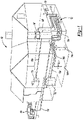
- the breaker box assembly 12 is disposed within the building 10 ( Figure 1 ) and includes a plurality of breaker modules 18 (such as breaker modules 18a, 18b, 18c, 18d, 18e, 18f), a distribution module 20, a cover module 22 and a pipe 23.
- the plurality of breaker modules 18 are removably attached to each other via fasteners 19 and are in fluid communication with each other.
- the plurality of breaker modules 18 are also in fluid communication with the distribution module 20.
- the breaker module 18a is removably attached to the distribution module 20 via fasteners 21 a and the breaker module 18f is removably attached to the cover module 22 via fasteners 21b.
- each breaker module 18 includes a body 24, a valve assembly 26 and a pipe assembly 28.
- the body 24 may be made of a metallic material, for example, and may define an inlet 32, first and second outlets 34, 36, and first and second passageways 38, 40.
- the inlet 32 is in fluid communication with the first outlet 34 of a respective breaker module 18.
- the inlet 32 of the breaker module 18a is in fluid communication with the gas source (not shown) via the pipe 23 and the distribution module 20.
- the second outlet 36 is in fluid communication with a respective appliance 14a, 14b, 14c, 14d, 14e, 14f via the pipe assembly 28 and a respective conduit 16a, 16b, 16c, 16d, 16e, 16f.
- the first passageway 38 extends between the inlet 32 and the first outlet 34.
- the second passageway 40 extends perpendicular to the first passageway 38.
- the second passageway 40 is also in fluid communication with the first passageway 38 and the second outlet 36.
- the body 24 also includes a first member 42 and a second member 44 that are attached to each other.
- An inlet portion 45 of the first member 42 is circular-shaped and includes a groove 46 extending 360 degrees around the inlet portion 45.
- the groove 46 receives a sealing member 48 (e.g., O-ring) such that fluid flowing through the first member 42 does not escape (i.e., leak out).
- the first member 42 of the body 24 defines the inlet 32, the first outlet 34 and the first passageway 38.
- the second member 44 defines the second outlet 36.
- the first and second members 30, 32 cooperate to define the second passageway 40.
- the valve assembly 26 is disposed within the body 24 of the breaker module 18 and includes a valve ring 50, a valve body 52 and a valve stem 56.
- the valve ring 50 is securely disposed within the second passageway 40 on a first seat 57 of the first member 42 and between the first seat 57 of the first member 42 and an end portion 58 of the second member 44.
- the end portion 58 has a sealing member 59 (e.g., O-ring) disposed within a groove formed therein.
- the valve body 52 is disposed within the second passageway 40 and is movably attached to the valve ring 50 between a first position in which fluid is allowed to flow to the first and second outlets 34, 36 and a second position in which fluid is permitted to flow to the first outlet 34 and prevented from flowing to the second outlet 36.
- first position fluid is allowed to flow through apertures (not shown) formed in the valve body 52 in route to the second outlet 36.
- the valve body 52 is in the second position, it sealingly abuts against the valve ring 50 (see module 18a of Figure 4 ) such that fluid is not allowed to flow through the second passageway 40 and the second outlet 36.
- the valve body 52 is disposed on a second seat 60 of the first member 42 when in the first position and removed from the second seat 60 when in the second position.
- the elongated valve stem 56 extends through the second member 44 of the body 24 such that a portion thereof is disposed above the second member 44.
- the valve stem 56 is moveable between a first position ( Figures 2-4 ) and a second position ( Figure 5 ).
- a biasing member 63 biases the valve stem 56 toward the first position.
- the valve stem 56 also includes a rib 62 extending outwardly from a middle portion thereof. The rib 62 is received in a groove 64 within the second member 44 and abuts against the second member 44 when the valve stem 56 is in the first position to prevent removal of the valve stem 56 from within the body 24.
- the pipe assembly 28 is attached to the second member 44 of the body 24 at one end and the respective conduit 16a, 16b, 16c, 16d, 16e, 16f at another end such that fluid flowing through the second outlet 36 flows through the pipe assembly 28 and the respective conduit 16a, 16b, 16c, 16d, 16e, 16f and to the respective appliance 14a, 14b, 14c, 14d, 14e, 14f.
- the pipe assembly 28 includes a conduit 66 and a valve assembly 68.
- the conduit 66 is attached (e.g., integrally attached, threadably attached, etc.) to the second member 44 of the body 24 such that the second outlet 36 and the conduit 66 are in fluid communication with each other.
- the conduit 66 is also attached (e.g., integrally attached, threadably attached, etc.) to the respective conduit 16a, 16b, 16c, 16d, 16e, 16f such that the conduit 66 and the respective conduit 16a, 16b, 16c, 16d, 16e, 16f are in fluid communication with each other.
- the valve assembly 68 is operable between a first position (see module 18a of Figure 4 ) in which fluid flowing through the second outlet 36 is prevented from flowing through the conduit 66 and a second position in which fluid flowing through the second outlet 36 is permitted to flow through the conduit 66.
- the valve assembly 68 is operable independently of the valve assembly 26 (i.e., the valve assembly 68 is movable between the first position and the second position regardless of the position of the valve assembly 26). In some configurations, the valve assemblies 26, 68 may be dependent on each other. That is, when the valve body 52 is moves to the second position then the valve stem 56, for example, may move the valve assembly 68 to the second position.
- the distribution module 20 is removably attached to the breaker module 18a and threadably attached to the pipe 23 such that fluid flowing through the pipe 23 is allowed to flow through the distribution module 20 and into the breaker box assembly 12.
- the distribution module 20 includes an aperture 70 that has a threaded portion and an unthreaded portion. As shown in Figure 4 , the pipe 23 is attached to the distribution module 20 via the threaded portion and the breaker module 18a is attached to the distribution module 20 via the unthreaded portion.
- the cover module 22 is removably attached to the breaker module 18f.
- An inlet portion 72 of the cover module 22 is circular-shaped and includes a groove 74 extending 360 degrees around the inlet portion 72.
- the groove 74 receives a sealing member 76 (e.g., O-ring) such that fluid flowing through the first outlet 34 of the breaker module 18f does not escape (i.e., leak out).
- a sealing member 76 e.g., O-ring
- the pipe 23 is threadably attached to the distribution module 20 at one end and receives fluid (e.g., natural gas) from a fluid source at another end.
- An electrical panel 79 is in communication with the pipe 23.
- valve body 52 This causes the valve body 52 to sealingly abut against the valve ring 50.
- fluid e.g., natural gas
- the other breaker modules 18b, 18c, 18d, 18e, 18f are allowed to provide fluid to the respective appliance 14b, 14c, 14d, 14e, 14f.
- fluid flow is prevented through the second outlet 36 of the breaker module 18a with the break or leak while fluid flow is permitted through the second outlet 36 of the other breaker modules 18b, 18c, 18d, 18e, 18f without the break or leak.
- the pressure difference needed to move the valve body 52 may be different for each breaker module 18a, 18b, 18c, 18d, 18e, 18f (i.e., the predetermined value is different for each breaker module 18a, 18b, 18c, 18d, 18e, 18f).
- Each breaker module 18a, 18b, 18c, 18d, 18e 18f may include indicia 84 on the body 24 thereof, which indicates that fluid flow through that breaker module has been stopped.
- Such indicia 84 may be lines that change from vertical to horizontal when fluid flow through the breaker module has been stopped (see breaker module 18a in Figure 3 ).
- the indicia may be a light that goes from green (indicating normal operating condition) to red (indicating a break or a leak) when the valve body 52 moves from the first position to the second position.
- a service technician may easily identify which conduit 16a, 16b, 16c, 16d, 16e, 16f and/or appliance 14a, 14b, 14c, 14d, 14e, 14f needs servicing.
- the service technician may push down on the valve stem 56 of the serviced breaker module 18a, 18b, 18c, 18d, 18e 18f, thereby resetting the valve assembly 26 and the indicia 84.
- the valve assembly 68 is in the first position prior to the service technician pushing down on the valve stem 56 to reset the valve body 52.
- sensors may be in communication with the electrical panel 79 and may be disposed at various locations of the conduits 16 and the appliances 14. The sensors may detect leaks in the conduits 16 and/or the appliances 14 that are below the pressures required to move the valve body 52 from the first position to the second position.
Claims (10)
- Ensemble boîtier organe de coupure (12), comprenant :
une pluralité de modules organes de coupure (18a, 18b, 18c, 18d, 18e, 18f) attachés de façon amovible les uns aux autres, chaque module organe de coupure incluant un corps (24) et un premier ensemble soupape (26) disposé à l'intérieur du corps, le corps incluant une entrée (32) et des première et seconde sorties (36, 34), le premier ensemble soupape étant mobile entre une première position, dans laquelle un fluide est autorisé de s'écouler vers les première et seconde sorties, et une seconde position, dans laquelle un fluide est empêché de s'écouler vers la première sortie et est permis de s'écouler vers la seconde sortie,
caractérisé en ce que
le premier ensemble soupape se déplace de la première position à la seconde position lorsqu'une différence de pression entre une première région (78) en amont du premier ensemble soupape et une seconde région (80) en aval du premier ensemble soupape dépasse une valeur prédéterminée. - Ensemble boîtier organe de coupure selon la revendication 1, dans lequel la valeur prédéterminée est différente pour chaque module organe de coupure.
- Ensemble boîtier organe de coupure selon la revendication 1, dans lequel la première sortie est appropriée pour être en communication fluidique avec un appareil respectif (14a, 14b, 14c, 14d, 14e, 14f).
- Ensemble boîtier organe de coupure selon la revendication 3, dans lequel la seconde sortie est en communication fluidique avec l'entrée d'un module organe de coupure respectif.
- Ensemble boîtier organe de coupure selon la revendication 4, dans lequel chaque module organe de coupure inclut un ensemble tuyau (28) en communication fluidique avec la première sortie et approprié pour être disposé en amont de l'appareil respectif.
- Ensemble boîtier organe de coupure selon la revendication 5, dans lequel l'ensemble tuyau inclut un second ensemble soupape (68) qui est mobile indépendamment du premier ensemble soupape entre une première position, dans laquelle un fluide s'écoulant à travers la première sortie est empêché de s'écouler à travers l'ensemble tuyau, et une seconde position, dans laquelle un fluide s'écoulant à travers la première sortie est permis de s'écouler à travers l'ensemble tuyau.
- Ensemble boîtier organe de coupure selon la revendication 7, dans lequel le corps de chaque module organe de coupure a un signal (84) qui indique l'instant auquel le premier ensemble soupape se déplace de la première position à la seconde position.
- Ensemble boîtier organe de coupure selon la revendication 1, dans lequel une partie d'entrée (45) du corps de chaque module organe de coupure inclut une rainure (46) formée dans celle-ci, et dans lequel un élément d'étanchéité (48) est disposé à l'intérieur de la rainure.
- Ensemble boîtier organe de coupure selon la revendication 1, dans lequel le fluide est du gaz naturel.
- Ensemble boîtier organe de coupure selon la revendication 1, dans lequel le premier ensemble soupape (26) inclut un corps de soupape (52) et une tige de soupape (56), et dans lequel la tige de soupape s'étend à travers le corps du module organe de coupure.
Applications Claiming Priority (1)
| Application Number | Priority Date | Filing Date | Title |
|---|---|---|---|
| US16/134,118 US10746406B2 (en) | 2018-09-18 | 2018-09-18 | Breaker box assembly |
Publications (2)
| Publication Number | Publication Date |
|---|---|
| EP3627017A1 EP3627017A1 (fr) | 2020-03-25 |
| EP3627017B1 true EP3627017B1 (fr) | 2022-03-30 |
Family
ID=67874266
Family Applications (1)
| Application Number | Title | Priority Date | Filing Date |
|---|---|---|---|
| EP19195490.8A Active EP3627017B1 (fr) | 2018-09-18 | 2019-09-05 | Ensemble de boîte de disjoncteurs |
Country Status (5)
| Country | Link |
|---|---|
| US (1) | US10746406B2 (fr) |
| EP (1) | EP3627017B1 (fr) |
| JP (1) | JP7431544B2 (fr) |
| AU (1) | AU2019226301B2 (fr) |
| CA (1) | CA3054913A1 (fr) |
Families Citing this family (2)
| Publication number | Priority date | Publication date | Assignee | Title |
|---|---|---|---|---|
| US11473957B2 (en) | 2020-01-02 | 2022-10-18 | Georg Fischer Central Plastics Llc | Meter bypass assembly having a housing including valve bodies rotationally fixed to opposing ends of a shaft |
| RU2749104C1 (ru) * | 2020-10-20 | 2021-06-04 | Махаббат Сапаргалиевич Байдулов | Клапан шаровой, срабатывающий от давления |
Citations (1)
| Publication number | Priority date | Publication date | Assignee | Title |
|---|---|---|---|---|
| US20140224895A1 (en) * | 2013-02-10 | 2014-08-14 | Hydra-Flex, Inc. | Air driven dispenser for delivery of undiluted chemical |
Family Cites Families (59)
| Publication number | Priority date | Publication date | Assignee | Title |
|---|---|---|---|---|
| US804033A (en) * | 1904-12-03 | 1905-11-07 | Johannes Th Pedersen | Lubricator. |
| US1659126A (en) | 1926-02-15 | 1928-02-14 | Jeff D Van Atta | Drain valve |
| US2645243A (en) * | 1948-05-17 | 1953-07-14 | Lon D Turner | Relief valve manifold |
| US3407827A (en) * | 1963-09-20 | 1968-10-29 | John L. Follett | Automatic shut-off valve |
| US3296859A (en) | 1964-05-20 | 1967-01-10 | Charles W Stewart | Meter bar |
| US3386473A (en) | 1965-05-17 | 1968-06-04 | J J Mooney | By-pass gas meter hanger |
| CA920912A (en) * | 1971-08-18 | 1973-02-13 | J. Dyck Gerhard | Stacked valve system |
| US4665941A (en) | 1981-03-27 | 1987-05-19 | Hudson David R | Fluid control of metering assemblies |
| AU568958B2 (en) * | 1984-02-02 | 1988-01-14 | Sung, Show Yen | Safety gas valve |
| US4609074A (en) * | 1984-07-16 | 1986-09-02 | Oil-Rite Corporation | Multiple oiler assembly |
| WO1995005554A2 (fr) * | 1993-08-09 | 1995-02-23 | Trevor Thomas Esplin | Dispositif de securite pour arreter un ecoulement en cas de trop-plein |
| EP0763718A4 (fr) | 1994-06-03 | 1997-11-05 | Tokyo Gas Co Ltd | Debitmetre |
| US5494071A (en) | 1994-06-03 | 1996-02-27 | Keystone International Holdings Corp. | Mounting system for pressure transmitters |
| US5542450A (en) | 1994-06-10 | 1996-08-06 | The Lubrizol Corporation | Apparatus for metering fluids |
| US5704391A (en) * | 1995-02-16 | 1998-01-06 | Umac Incorporated | Gravity-operated gas shut-off valve |
| JP3105433B2 (ja) | 1995-10-17 | 2000-10-30 | 松下電器産業株式会社 | 配管漏洩検知装置 |
| US5836340A (en) | 1996-01-19 | 1998-11-17 | A. Y. Mcdonald Mfg. Co. | Auxiliary gas connection for meter sets |
| RU2130591C1 (ru) | 1996-11-01 | 1999-05-20 | Тонконогов Александр Яковлевич | Устройство для присоединения расходомера |
| US5785086A (en) | 1997-07-08 | 1998-07-28 | Boyce; J. Stephen | Valve assembly for metered fluid flow |
| US5971003A (en) | 1998-02-19 | 1999-10-26 | R. W. Lyall & Company, Inc. | Apparatus to service gas meters |
| US5918624A (en) | 1998-03-12 | 1999-07-06 | Young; William C. | Gas meter quick change meter bar |
| JPH11287676A (ja) | 1998-04-01 | 1999-10-19 | Matsushita Electric Ind Co Ltd | 流量計測装置 |
| JP4174878B2 (ja) | 1998-11-11 | 2008-11-05 | 松下電器産業株式会社 | 流量計測装置 |
| JP2000249619A (ja) | 1999-03-02 | 2000-09-14 | Tokyo Gas Co Ltd | ガス漏洩検知方法 |
| JP3982946B2 (ja) | 1999-05-25 | 2007-09-26 | 大阪瓦斯株式会社 | ガスメータの取付け治具 |
| EP1164361A1 (fr) | 2000-06-14 | 2001-12-19 | Abb Research Ltd. | Compteur à gaz |
| JP3451078B2 (ja) | 2001-11-06 | 2003-09-29 | 株式会社藤井合金製作所 | ガスメータの配管構造 |
| JP2004185917A (ja) | 2002-12-02 | 2004-07-02 | Sanyo Electric Co Ltd | ガスメータ及び燃料電池システム |
| US6929032B2 (en) * | 2003-04-02 | 2005-08-16 | Sea Tech, Inc. | Manifold |
| GB2408592B (en) | 2003-11-27 | 2005-11-16 | James Ian Oswald | Household energy management system |
| US7034704B2 (en) | 2004-05-24 | 2006-04-25 | Mahowald Peter H | System powered via signal on gas pipe |
| JP4399553B2 (ja) | 2004-05-31 | 2010-01-20 | 株式会社荏原製作所 | 燃料電池システム |
| FI116580B (fi) | 2004-07-23 | 2005-12-30 | Kytoelae Instrumenttitehdas | Virtaussäädin |
| JP2006053073A (ja) | 2004-08-12 | 2006-02-23 | Osaka Gas Co Ltd | ガス通流状態認識装置 |
| US7347219B2 (en) | 2005-10-20 | 2008-03-25 | A. Y. Mcdonald Mfg. Co. | Meter bar and metering system |
| DE102005051307A1 (de) | 2005-10-26 | 2007-05-03 | As-Antriebstechnik Und Service Gmbh | Vorrichtung zur Bestimmung eines Volumenstroms |
| JP4889365B2 (ja) | 2006-04-25 | 2012-03-07 | パナソニック株式会社 | ガス器具管理システム及びガス供給システム |
| US20070289647A1 (en) | 2006-06-20 | 2007-12-20 | Elbi International S.P.A. | Mixer valve unit for liquids with associated flow rate meter, particularly for electrical domestic appliances |
| JP4935334B2 (ja) | 2006-12-11 | 2012-05-23 | パナソニック株式会社 | 流量計測装置とこの装置を用いたガス供給システム |
| WO2008081908A1 (fr) | 2006-12-28 | 2008-07-10 | Panasonic Corporation | Débitmètre et système d'alimentation en gaz |
| US20170145668A1 (en) | 2007-11-02 | 2017-05-25 | OW Investors, LLC (dba MARS Company) | Residential fire service fixture ii |
| JP5065920B2 (ja) | 2008-01-17 | 2012-11-07 | 矢崎総業株式会社 | 集中監視システム |
| JP5082989B2 (ja) | 2008-03-31 | 2012-11-28 | 日立金属株式会社 | 流量制御装置、その検定方法及び流量制御方法 |
| CN102369395B (zh) | 2009-01-29 | 2013-12-18 | 松下电器产业株式会社 | 燃气切断装置 |
| EP2509144A1 (fr) | 2009-12-01 | 2012-10-10 | Panasonic Corporation | Système de production d'énergie |
| JP5789162B2 (ja) | 2011-09-28 | 2015-10-07 | 京セラ株式会社 | エネルギー管理システム、ガスメータ及びエネルギー管理装置 |
| JP5914877B2 (ja) | 2011-11-17 | 2016-05-11 | パナソニックIpマネジメント株式会社 | ガス流量検出装置及びガス流量検出方法 |
| US8839815B2 (en) | 2011-12-15 | 2014-09-23 | Honeywell International Inc. | Gas valve with electronic cycle counter |
| US9074770B2 (en) | 2011-12-15 | 2015-07-07 | Honeywell International Inc. | Gas valve with electronic valve proving system |
| US9557059B2 (en) | 2011-12-15 | 2017-01-31 | Honeywell International Inc | Gas valve with communication link |
| ES2424398B1 (es) * | 2012-02-29 | 2014-09-02 | Válvulas Arco S.L. | Estructura modular de colectores antical |
| US9212752B2 (en) | 2012-03-26 | 2015-12-15 | Jordan Gardner | Gas bypass device |
| JP2013221863A (ja) | 2012-04-17 | 2013-10-28 | Panasonic Corp | 流体器具情報提供装置 |
| JP5945782B2 (ja) | 2012-06-28 | 2016-07-05 | パナソニックIpマネジメント株式会社 | 流体計測装置 |
| JP5914870B2 (ja) | 2012-06-28 | 2016-05-11 | パナソニックIpマネジメント株式会社 | 流体計測装置 |
| US20150114490A1 (en) * | 2013-10-28 | 2015-04-30 | Leakshield, Llc | Water management system |
| CN105333312B (zh) | 2015-11-05 | 2018-03-27 | 重庆金鑫智慧科技有限公司 | 采用物联网控制技术的用气安全管理系统 |
| US10247594B2 (en) | 2017-04-26 | 2019-04-02 | Georg Fischer Central Plastics Llc | Meter bypass adapter |
| JP6886147B2 (ja) | 2017-08-07 | 2021-06-16 | 北海道瓦斯株式会社 | ガスメータ用継手ユニット |
-
2018
- 2018-09-18 US US16/134,118 patent/US10746406B2/en active Active
-
2019
- 2019-09-05 EP EP19195490.8A patent/EP3627017B1/fr active Active
- 2019-09-09 CA CA3054913A patent/CA3054913A1/fr active Pending
- 2019-09-10 AU AU2019226301A patent/AU2019226301B2/en active Active
- 2019-09-17 JP JP2019168342A patent/JP7431544B2/ja active Active
Patent Citations (1)
| Publication number | Priority date | Publication date | Assignee | Title |
|---|---|---|---|---|
| US20140224895A1 (en) * | 2013-02-10 | 2014-08-14 | Hydra-Flex, Inc. | Air driven dispenser for delivery of undiluted chemical |
Also Published As
| Publication number | Publication date |
|---|---|
| US10746406B2 (en) | 2020-08-18 |
| AU2019226301B2 (en) | 2021-03-11 |
| AU2019226301A1 (en) | 2020-04-02 |
| JP2020076493A (ja) | 2020-05-21 |
| CA3054913A1 (fr) | 2020-03-18 |
| JP7431544B2 (ja) | 2024-02-15 |
| NZ757089A (en) | 2020-10-30 |
| US20200088407A1 (en) | 2020-03-19 |
| EP3627017A1 (fr) | 2020-03-25 |
Similar Documents
| Publication | Publication Date | Title |
|---|---|---|
| US20080314466A1 (en) | Valves for use with tankless water heater | |
| US7681596B2 (en) | Isolation valve with valve in drain | |
| US7621295B2 (en) | System for controlling fluid flow to an appliance | |
| EP3627017B1 (fr) | Ensemble de boîte de disjoncteurs | |
| US20070089790A1 (en) | Assembly for connecting a water supply to heating systems with a water heater | |
| EP3332855B1 (fr) | Dispositif de filtration et de séparation des saletés | |
| US7059340B2 (en) | Valve assembly for pipe disconnectors | |
| US20230313508A1 (en) | Compact valve assembly | |
| US7178544B2 (en) | Combination shut-off and resetable excess flow valve | |
| US11248992B2 (en) | Systems and methods for accessing and monitoring a fluid within a pressurized pipe | |
| NZ757089B2 (en) | Breaker box assembly | |
| EP1828652B1 (fr) | Corps de vanne universel pour liquide | |
| CN107044544B (zh) | 用于在各压力和温度下对流体流动控制设备进行启动测试的组件 | |
| US20210340741A1 (en) | Plumbing fitting | |
| GB2443209A (en) | Mains water meter mounted on stop tap body | |
| GB2582028A (en) | Magnetic filter for a central heating system | |
| Clarke | Best Practices Guide Valve Selection for Pressure Zone Management | |
| CN112344053A (zh) | 具有自动关闭端口的管路系统 | |
| Regulators et al. | 2.3 WATER PRESSURE-REDUCING VALVES | |
| US20110253067A1 (en) | Pipe fitting |
Legal Events
| Date | Code | Title | Description |
|---|---|---|---|
| PUAI | Public reference made under article 153(3) epc to a published international application that has entered the european phase |
Free format text: ORIGINAL CODE: 0009012 |
|
| STAA | Information on the status of an ep patent application or granted ep patent |
Free format text: STATUS: THE APPLICATION HAS BEEN PUBLISHED |
|
| AK | Designated contracting states |
Kind code of ref document: A1 Designated state(s): AL AT BE BG CH CY CZ DE DK EE ES FI FR GB GR HR HU IE IS IT LI LT LU LV MC MK MT NL NO PL PT RO RS SE SI SK SM TR |
|
| AX | Request for extension of the european patent |
Extension state: BA ME |
|
| STAA | Information on the status of an ep patent application or granted ep patent |
Free format text: STATUS: REQUEST FOR EXAMINATION WAS MADE |
|
| 17P | Request for examination filed |
Effective date: 20200819 |
|
| RBV | Designated contracting states (corrected) |
Designated state(s): AL AT BE BG CH CY CZ DE DK EE ES FI FR GB GR HR HU IE IS IT LI LT LU LV MC MK MT NL NO PL PT RO RS SE SI SK SM TR |
|
| STAA | Information on the status of an ep patent application or granted ep patent |
Free format text: STATUS: EXAMINATION IS IN PROGRESS |
|
| 17Q | First examination report despatched |
Effective date: 20201105 |
|
| GRAP | Despatch of communication of intention to grant a patent |
Free format text: ORIGINAL CODE: EPIDOSNIGR1 |
|
| STAA | Information on the status of an ep patent application or granted ep patent |
Free format text: STATUS: GRANT OF PATENT IS INTENDED |
|
| INTG | Intention to grant announced |
Effective date: 20211207 |
|
| GRAS | Grant fee paid |
Free format text: ORIGINAL CODE: EPIDOSNIGR3 |
|
| GRAA | (expected) grant |
Free format text: ORIGINAL CODE: 0009210 |
|
| STAA | Information on the status of an ep patent application or granted ep patent |
Free format text: STATUS: THE PATENT HAS BEEN GRANTED |
|
| AK | Designated contracting states |
Kind code of ref document: B1 Designated state(s): AL AT BE BG CH CY CZ DE DK EE ES FI FR GB GR HR HU IE IS IT LI LT LU LV MC MK MT NL NO PL PT RO RS SE SI SK SM TR |
|
| REG | Reference to a national code |
Ref country code: GB Ref legal event code: FG4D |
|
| REG | Reference to a national code |
Ref country code: CH Ref legal event code: EP |
|
| REG | Reference to a national code |
Ref country code: AT Ref legal event code: REF Ref document number: 1479492 Country of ref document: AT Kind code of ref document: T Effective date: 20220415 |
|
| REG | Reference to a national code |
Ref country code: DE Ref legal event code: R096 Ref document number: 602019012997 Country of ref document: DE |
|
| REG | Reference to a national code |
Ref country code: IE Ref legal event code: FG4D |
|
| REG | Reference to a national code |
Ref country code: LT Ref legal event code: MG9D |
|
| PG25 | Lapsed in a contracting state [announced via postgrant information from national office to epo] |
Ref country code: SE Free format text: LAPSE BECAUSE OF FAILURE TO SUBMIT A TRANSLATION OF THE DESCRIPTION OR TO PAY THE FEE WITHIN THE PRESCRIBED TIME-LIMIT Effective date: 20220330 Ref country code: RS Free format text: LAPSE BECAUSE OF FAILURE TO SUBMIT A TRANSLATION OF THE DESCRIPTION OR TO PAY THE FEE WITHIN THE PRESCRIBED TIME-LIMIT Effective date: 20220330 Ref country code: NO Free format text: LAPSE BECAUSE OF FAILURE TO SUBMIT A TRANSLATION OF THE DESCRIPTION OR TO PAY THE FEE WITHIN THE PRESCRIBED TIME-LIMIT Effective date: 20220630 Ref country code: LT Free format text: LAPSE BECAUSE OF FAILURE TO SUBMIT A TRANSLATION OF THE DESCRIPTION OR TO PAY THE FEE WITHIN THE PRESCRIBED TIME-LIMIT Effective date: 20220330 Ref country code: HR Free format text: LAPSE BECAUSE OF FAILURE TO SUBMIT A TRANSLATION OF THE DESCRIPTION OR TO PAY THE FEE WITHIN THE PRESCRIBED TIME-LIMIT Effective date: 20220330 Ref country code: BG Free format text: LAPSE BECAUSE OF FAILURE TO SUBMIT A TRANSLATION OF THE DESCRIPTION OR TO PAY THE FEE WITHIN THE PRESCRIBED TIME-LIMIT Effective date: 20220630 |
|
| REG | Reference to a national code |
Ref country code: NL Ref legal event code: MP Effective date: 20220330 |
|
| REG | Reference to a national code |
Ref country code: AT Ref legal event code: MK05 Ref document number: 1479492 Country of ref document: AT Kind code of ref document: T Effective date: 20220330 |
|
| PG25 | Lapsed in a contracting state [announced via postgrant information from national office to epo] |
Ref country code: LV Free format text: LAPSE BECAUSE OF FAILURE TO SUBMIT A TRANSLATION OF THE DESCRIPTION OR TO PAY THE FEE WITHIN THE PRESCRIBED TIME-LIMIT Effective date: 20220330 Ref country code: GR Free format text: LAPSE BECAUSE OF FAILURE TO SUBMIT A TRANSLATION OF THE DESCRIPTION OR TO PAY THE FEE WITHIN THE PRESCRIBED TIME-LIMIT Effective date: 20220701 Ref country code: FI Free format text: LAPSE BECAUSE OF FAILURE TO SUBMIT A TRANSLATION OF THE DESCRIPTION OR TO PAY THE FEE WITHIN THE PRESCRIBED TIME-LIMIT Effective date: 20220330 |
|
| PG25 | Lapsed in a contracting state [announced via postgrant information from national office to epo] |
Ref country code: NL Free format text: LAPSE BECAUSE OF FAILURE TO SUBMIT A TRANSLATION OF THE DESCRIPTION OR TO PAY THE FEE WITHIN THE PRESCRIBED TIME-LIMIT Effective date: 20220330 |
|
| PG25 | Lapsed in a contracting state [announced via postgrant information from national office to epo] |
Ref country code: SM Free format text: LAPSE BECAUSE OF FAILURE TO SUBMIT A TRANSLATION OF THE DESCRIPTION OR TO PAY THE FEE WITHIN THE PRESCRIBED TIME-LIMIT Effective date: 20220330 Ref country code: SK Free format text: LAPSE BECAUSE OF FAILURE TO SUBMIT A TRANSLATION OF THE DESCRIPTION OR TO PAY THE FEE WITHIN THE PRESCRIBED TIME-LIMIT Effective date: 20220330 Ref country code: RO Free format text: LAPSE BECAUSE OF FAILURE TO SUBMIT A TRANSLATION OF THE DESCRIPTION OR TO PAY THE FEE WITHIN THE PRESCRIBED TIME-LIMIT Effective date: 20220330 Ref country code: PT Free format text: LAPSE BECAUSE OF FAILURE TO SUBMIT A TRANSLATION OF THE DESCRIPTION OR TO PAY THE FEE WITHIN THE PRESCRIBED TIME-LIMIT Effective date: 20220801 Ref country code: ES Free format text: LAPSE BECAUSE OF FAILURE TO SUBMIT A TRANSLATION OF THE DESCRIPTION OR TO PAY THE FEE WITHIN THE PRESCRIBED TIME-LIMIT Effective date: 20220330 Ref country code: EE Free format text: LAPSE BECAUSE OF FAILURE TO SUBMIT A TRANSLATION OF THE DESCRIPTION OR TO PAY THE FEE WITHIN THE PRESCRIBED TIME-LIMIT Effective date: 20220330 Ref country code: CZ Free format text: LAPSE BECAUSE OF FAILURE TO SUBMIT A TRANSLATION OF THE DESCRIPTION OR TO PAY THE FEE WITHIN THE PRESCRIBED TIME-LIMIT Effective date: 20220330 Ref country code: AT Free format text: LAPSE BECAUSE OF FAILURE TO SUBMIT A TRANSLATION OF THE DESCRIPTION OR TO PAY THE FEE WITHIN THE PRESCRIBED TIME-LIMIT Effective date: 20220330 |
|
| PG25 | Lapsed in a contracting state [announced via postgrant information from national office to epo] |
Ref country code: PL Free format text: LAPSE BECAUSE OF FAILURE TO SUBMIT A TRANSLATION OF THE DESCRIPTION OR TO PAY THE FEE WITHIN THE PRESCRIBED TIME-LIMIT Effective date: 20220330 Ref country code: IS Free format text: LAPSE BECAUSE OF FAILURE TO SUBMIT A TRANSLATION OF THE DESCRIPTION OR TO PAY THE FEE WITHIN THE PRESCRIBED TIME-LIMIT Effective date: 20220730 Ref country code: AL Free format text: LAPSE BECAUSE OF FAILURE TO SUBMIT A TRANSLATION OF THE DESCRIPTION OR TO PAY THE FEE WITHIN THE PRESCRIBED TIME-LIMIT Effective date: 20220330 |
|
| REG | Reference to a national code |
Ref country code: DE Ref legal event code: R097 Ref document number: 602019012997 Country of ref document: DE |
|
| PG25 | Lapsed in a contracting state [announced via postgrant information from national office to epo] |
Ref country code: DK Free format text: LAPSE BECAUSE OF FAILURE TO SUBMIT A TRANSLATION OF THE DESCRIPTION OR TO PAY THE FEE WITHIN THE PRESCRIBED TIME-LIMIT Effective date: 20220330 |
|
| PLBE | No opposition filed within time limit |
Free format text: ORIGINAL CODE: 0009261 |
|
| STAA | Information on the status of an ep patent application or granted ep patent |
Free format text: STATUS: NO OPPOSITION FILED WITHIN TIME LIMIT |
|
| 26N | No opposition filed |
Effective date: 20230103 |
|
| PG25 | Lapsed in a contracting state [announced via postgrant information from national office to epo] |
Ref country code: MC Free format text: LAPSE BECAUSE OF FAILURE TO SUBMIT A TRANSLATION OF THE DESCRIPTION OR TO PAY THE FEE WITHIN THE PRESCRIBED TIME-LIMIT Effective date: 20220330 |
|
| REG | Reference to a national code |
Ref country code: BE Ref legal event code: MM Effective date: 20220930 |
|
| PG25 | Lapsed in a contracting state [announced via postgrant information from national office to epo] |
Ref country code: SI Free format text: LAPSE BECAUSE OF FAILURE TO SUBMIT A TRANSLATION OF THE DESCRIPTION OR TO PAY THE FEE WITHIN THE PRESCRIBED TIME-LIMIT Effective date: 20220330 |
|
| PG25 | Lapsed in a contracting state [announced via postgrant information from national office to epo] |
Ref country code: LU Free format text: LAPSE BECAUSE OF NON-PAYMENT OF DUE FEES Effective date: 20220905 |
|
| P01 | Opt-out of the competence of the unified patent court (upc) registered |
Effective date: 20230529 |
|
| PG25 | Lapsed in a contracting state [announced via postgrant information from national office to epo] |
Ref country code: IE Free format text: LAPSE BECAUSE OF NON-PAYMENT OF DUE FEES Effective date: 20220905 |
|
| PG25 | Lapsed in a contracting state [announced via postgrant information from national office to epo] |
Ref country code: BE Free format text: LAPSE BECAUSE OF NON-PAYMENT OF DUE FEES Effective date: 20220930 |
|
| PGFP | Annual fee paid to national office [announced via postgrant information from national office to epo] |
Ref country code: GB Payment date: 20230920 Year of fee payment: 5 |
|
| PGFP | Annual fee paid to national office [announced via postgrant information from national office to epo] |
Ref country code: FR Payment date: 20230928 Year of fee payment: 5 Ref country code: DE Payment date: 20230920 Year of fee payment: 5 |
|
| PGFP | Annual fee paid to national office [announced via postgrant information from national office to epo] |
Ref country code: CH Payment date: 20231001 Year of fee payment: 5 Ref country code: IT Payment date: 20230927 Year of fee payment: 5 |
|
| PG25 | Lapsed in a contracting state [announced via postgrant information from national office to epo] |
Ref country code: HU Free format text: LAPSE BECAUSE OF FAILURE TO SUBMIT A TRANSLATION OF THE DESCRIPTION OR TO PAY THE FEE WITHIN THE PRESCRIBED TIME-LIMIT; INVALID AB INITIO Effective date: 20190905 |
|
| PG25 | Lapsed in a contracting state [announced via postgrant information from national office to epo] |
Ref country code: CY Free format text: LAPSE BECAUSE OF FAILURE TO SUBMIT A TRANSLATION OF THE DESCRIPTION OR TO PAY THE FEE WITHIN THE PRESCRIBED TIME-LIMIT Effective date: 20220330 |