EP3625448B1 - Verbrennungsmotor mit äusserer gemischbildung und ausgleichsbehälter zur vermeidung von rückzündung - Google Patents
Verbrennungsmotor mit äusserer gemischbildung und ausgleichsbehälter zur vermeidung von rückzündung Download PDFInfo
- Publication number
- EP3625448B1 EP3625448B1 EP18719040.0A EP18719040A EP3625448B1 EP 3625448 B1 EP3625448 B1 EP 3625448B1 EP 18719040 A EP18719040 A EP 18719040A EP 3625448 B1 EP3625448 B1 EP 3625448B1
- Authority
- EP
- European Patent Office
- Prior art keywords
- internal combustion
- compensation vessel
- expansion tank
- combustion engine
- mixture formation
- Prior art date
- Legal status (The legal status is an assumption and is not a legal conclusion. Google has not performed a legal analysis and makes no representation as to the accuracy of the status listed.)
- Active
Links
Images


Classifications
-
- F—MECHANICAL ENGINEERING; LIGHTING; HEATING; WEAPONS; BLASTING
- F02—COMBUSTION ENGINES; HOT-GAS OR COMBUSTION-PRODUCT ENGINE PLANTS
- F02M—SUPPLYING COMBUSTION ENGINES IN GENERAL WITH COMBUSTIBLE MIXTURES OR CONSTITUENTS THEREOF
- F02M35/00—Combustion-air cleaners, air intakes, intake silencers, or induction systems specially adapted for, or arranged on, internal-combustion engines
- F02M35/10—Air intakes; Induction systems
- F02M35/10242—Devices or means connected to or integrated into air intakes; Air intakes combined with other engine or vehicle parts
- F02M35/10275—Means to avoid a change in direction of incoming fluid, e.g. all intake ducts diverging from plenum chamber at acute angles; Check valves; Flame arrestors for backfire prevention
-
- F—MECHANICAL ENGINEERING; LIGHTING; HEATING; WEAPONS; BLASTING
- F02—COMBUSTION ENGINES; HOT-GAS OR COMBUSTION-PRODUCT ENGINE PLANTS
- F02M—SUPPLYING COMBUSTION ENGINES IN GENERAL WITH COMBUSTIBLE MIXTURES OR CONSTITUENTS THEREOF
- F02M35/00—Combustion-air cleaners, air intakes, intake silencers, or induction systems specially adapted for, or arranged on, internal-combustion engines
- F02M35/10—Air intakes; Induction systems
- F02M35/104—Intake manifolds
- F02M35/112—Intake manifolds for engines with cylinders all in one line
-
- F—MECHANICAL ENGINEERING; LIGHTING; HEATING; WEAPONS; BLASTING
- F02—COMBUSTION ENGINES; HOT-GAS OR COMBUSTION-PRODUCT ENGINE PLANTS
- F02B—INTERNAL-COMBUSTION PISTON ENGINES; COMBUSTION ENGINES IN GENERAL
- F02B27/00—Use of kinetic or wave energy of charge in induction systems, or of combustion residues in exhaust systems, for improving quantity of charge or for increasing removal of combustion residues
- F02B27/02—Use of kinetic or wave energy of charge in induction systems, or of combustion residues in exhaust systems, for improving quantity of charge or for increasing removal of combustion residues the systems having variable, i.e. adjustable, cross-sectional areas, chambers of variable volume, or like variable means
- F02B27/0226—Use of kinetic or wave energy of charge in induction systems, or of combustion residues in exhaust systems, for improving quantity of charge or for increasing removal of combustion residues the systems having variable, i.e. adjustable, cross-sectional areas, chambers of variable volume, or like variable means characterised by the means generating the charging effect
- F02B27/0268—Valves
-
- F—MECHANICAL ENGINEERING; LIGHTING; HEATING; WEAPONS; BLASTING
- F02—COMBUSTION ENGINES; HOT-GAS OR COMBUSTION-PRODUCT ENGINE PLANTS
- F02M—SUPPLYING COMBUSTION ENGINES IN GENERAL WITH COMBUSTIBLE MIXTURES OR CONSTITUENTS THEREOF
- F02M21/00—Apparatus for supplying engines with non-liquid fuels, e.g. gaseous fuels stored in liquid form
- F02M21/02—Apparatus for supplying engines with non-liquid fuels, e.g. gaseous fuels stored in liquid form for gaseous fuels
- F02M21/04—Gas-air mixing apparatus
-
- F—MECHANICAL ENGINEERING; LIGHTING; HEATING; WEAPONS; BLASTING
- F02—COMBUSTION ENGINES; HOT-GAS OR COMBUSTION-PRODUCT ENGINE PLANTS
- F02M—SUPPLYING COMBUSTION ENGINES IN GENERAL WITH COMBUSTIBLE MIXTURES OR CONSTITUENTS THEREOF
- F02M35/00—Combustion-air cleaners, air intakes, intake silencers, or induction systems specially adapted for, or arranged on, internal-combustion engines
- F02M35/10—Air intakes; Induction systems
- F02M35/10209—Fluid connections to the air intake system; their arrangement of pipes, valves or the like
- F02M35/10216—Fuel injectors; Fuel pipes or rails; Fuel pumps or pressure regulators
-
- F—MECHANICAL ENGINEERING; LIGHTING; HEATING; WEAPONS; BLASTING
- F02—COMBUSTION ENGINES; HOT-GAS OR COMBUSTION-PRODUCT ENGINE PLANTS
- F02M—SUPPLYING COMBUSTION ENGINES IN GENERAL WITH COMBUSTIBLE MIXTURES OR CONSTITUENTS THEREOF
- F02M35/00—Combustion-air cleaners, air intakes, intake silencers, or induction systems specially adapted for, or arranged on, internal-combustion engines
- F02M35/10—Air intakes; Induction systems
- F02M35/10209—Fluid connections to the air intake system; their arrangement of pipes, valves or the like
- F02M35/10222—Exhaust gas recirculation [EGR]; Positive crankcase ventilation [PCV]; Additional air admission, lubricant or fuel vapour admission
-
- Y—GENERAL TAGGING OF NEW TECHNOLOGICAL DEVELOPMENTS; GENERAL TAGGING OF CROSS-SECTIONAL TECHNOLOGIES SPANNING OVER SEVERAL SECTIONS OF THE IPC; TECHNICAL SUBJECTS COVERED BY FORMER USPC CROSS-REFERENCE ART COLLECTIONS [XRACs] AND DIGESTS
- Y02—TECHNOLOGIES OR APPLICATIONS FOR MITIGATION OR ADAPTATION AGAINST CLIMATE CHANGE
- Y02T—CLIMATE CHANGE MITIGATION TECHNOLOGIES RELATED TO TRANSPORTATION
- Y02T10/00—Road transport of goods or passengers
- Y02T10/10—Internal combustion engine [ICE] based vehicles
- Y02T10/30—Use of alternative fuels, e.g. biofuels
Definitions
- An internal combustion engine is known with an expansion tank that is formed by two volumes arranged one behind the other.
- the inlet of the expansion tank is on a first side and the outlet is on an opposite second side.
- Such backfire protection devices are known from the KR 20010108884 A , in which a valve plate held by internal coil springs is intended to ensure possible pressure equalization.
- the EP1971763B1 discloses a pressure sensor for detecting backfiring and subsequently controlling a throttle valve to reduce the pressure.
- EP2054589B1 discloses a pressure control valve to prevent backfiring.
- the EP1647684A2 reveals fluidic solutions for a hydrogen-powered combustion engine to prevent backfiring.
- the object is achieved by a device according to claim 1 and a method according to claim 11.
- the advantage here is that backfires and their effects cannot penetrate into the air filter.
- throttle valve is arranged between the intake manifold and the mixture formation device.
- a further advantageous development provides that the mixture formation device is designed as a gas mixer.
- the mixture formation device is designed as a carburetor.
- the expansion tank is designed in the shape of steps.
- a further advantageous development provides that the mixture formation device and the expansion tank are connected by means of a flexible pipe element.
- At least one flow straightener is arranged between the expansion tank and the mixture formation device.
- an expansion tank i.e. an air volume between the air filter and the mixture-forming system (carburettor, air-gas mixer)
- the harmful effect of the "back fire” can be significantly reduced.
- the hot combustion gases that expand in the opposite direction to the normal flow as a result of the combustion (“back fire”) are mixed and cooled with non-flammable fresh air in the expansion tank and the "back fire” pressure wave is reduced.
- the subject of this patent is the expansion tank described and outlined below. This can also be made by clever internal design lead to a reflection of the pressure wave on the vessel walls, which can further reduce the reduction of the pressure wave and the spread of the hot combustion gases.
- a flow straightener can be installed.
- This flow straightener consists of a more or less dense metal grid or net.
- This close-meshed grid is installed in the intake system in the direction of flow before the mixture-forming system. In the event of a "back fire", the flame spreading against the normal flow direction must pass through the flow straightener. The close-meshed metal grid cools the flame significantly. This prevents damage to the air-conducting system.
- Another advantage of the combination shown here consisting of an expansion tank and a flow straightener, is its reducing effect on gas pulsations in the intake manifold. Every valve-controlled reciprocating piston engine generates pulsations in the intake manifold. These pulsations can potentially have a negative effect on mixture formation.
- the expansion tank alone significantly reduces the amplitude of the pressure pulses. When the expansion tank is used in combination with a flow straightener, these pressure pulses are further reduced. This allows for improved mixture formation. Engine power and torque can be increased while simultaneously reducing harmful exhaust emissions.
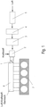
- FIG. 1 an internal combustion engine 7 is shown with a flow straightener 3 and an expansion tank 4, which are arranged in front of the carburetor 2 in the direction of flow.
- the intake air of the internal combustion engine 7 passes through the air filter 5 and then passes through the expansion tank inlet 8 into the stepped expansion tank 4.
- the intake air in the expansion tank 4 passes through the expansion tank outlet 9, the diameter of which is larger than that of the expansion tank inlet 8, into the flow straightener 3.
- the flow straightener 3 consists of a flow straightener housing and a flow straightener insert.
- the flow straightener insert consists of a close-meshed metal grid.
- the flow straightener insert consists of a honeycomb-like extruded profile.
- the flow straightener insert is preferably made of a thermally conductive metal such as copper or aluminum.
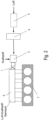
- Figure 2 shows an internal combustion engine 7 with an expansion tank 4, which is arranged in front of the carburetor 2 in the flow direction of the intake air.
- the intake air of the internal combustion engine 7 passes through the air filter 5 and then passes through the expansion tank inlet 8 into the stepped expansion tank 4.
- the intake air, which is in the expansion tank 4, passes through the expansion tank outlet 9, whose diameter is larger than that of the expansion tank inlet 8, into the carburetor 2.
- a stepped expansion tank 4 in the form of an air intake box is disclosed.
- the expansion tank 4 has an expansion tank inlet 8 and an expansion tank outlet 9.
- the outer surface of the expansion tank 4 is arranged in a step-like manner between the expansion tank inlet 8 and the expansion tank outlet 9, with a fastening surface 10 for fastening the expansion tank 4 to the internal combustion engine being provided in the first step from the expansion tank inlet 8 in the direction of the expansion tank outlet 9.
- the outer surface of the expansion tank 4 on the side opposite the expansion tank inlet 8 and the expansion tank outlet 9 is arranged in a step-like manner, with a fastening surface 10 for fastening the expansion tank 4 to the internal combustion engine being provided in each step.
- the housing of the expansion tank 4 consists of a thermally conductive material, for example metal.
- the total volume of the expansion tank is between 2 and 5 liters.
- the diameter ratio of the expansion tank inlet 8 of the expansion tank to the expansion tank outlet 9 is approximately 58/80.
- the outer surface of the expansion tank 4 has only one step between the expansion tank inlet 8 and the expansion tank outlet 9, the expansion tank 4 essentially consists of two compensation volumes which are connected by means of a flow constriction in the area of the step.
- This embodiment of the expansion tank 4 has a volume of approximately 3 liters.
- Figure 4 shows the temperature and pressure curve in the intake manifold over time without the Figure 2 expansion tank shown.
- Figure 6 shows a table-like comparison of the pressure and temperature values in the intake manifold of the same engine, once with and once without an expansion tank.
Landscapes
- Engineering & Computer Science (AREA)
- Chemical & Material Sciences (AREA)
- Combustion & Propulsion (AREA)
- Mechanical Engineering (AREA)
- General Engineering & Computer Science (AREA)
- Chemical Kinetics & Catalysis (AREA)
- General Chemical & Material Sciences (AREA)
- Oil, Petroleum & Natural Gas (AREA)
- Characterised By The Charging Evacuation (AREA)
- Control Of Throttle Valves Provided In The Intake System Or In The Exhaust System (AREA)
- Exhaust Silencers (AREA)
Description
- Bei Verbrennungsmotoren mit äußerer Gemischbildung wird vor den Einlassventilen ein entflammbares Luft-Kraftstoffgemisch erzeugt. Dabei kann es zur ungewollten Verbrennung im Saugrohr des Motors ("Back-Fire") kommen. Je größer das Saugrohr und je größer die Masse an zündfähigem Gemisch vor den Einlassventilen ist, desto größer ist das Risiko eines Schadens.
- Aus der
JP H08 254162 A - Derartige Rückzündungsschutzvorrichtungen sind bekannt aus der
KR 20010108884 A - Weiter sind derartige Rückzündungsschutzvorrichtungen auch aus der
KR 20020041902 A - Aus der
US 20060005808 A1 ist bekannt, dass Rückzündung mittels einer Drosselklappe verhindert werden soll. - Die
EP 1971763 B1 offenbart einen Drucksensor zur Ermittlung einer Rückzündung und der anschließenden Ansteuerung einer Drosselklappe zum Druckabbau. - In der
DE 2526550 A1 wird ein Nebenauslass gezeigt, der Druckanstiege bei Rückzündungen verhindern soll. - Zur Kühlung der Rückzündung schlägt die
JP 57181964 A - Aus der
WO 9966189 A1 - In der
EP 715684 B1 -
EP 2054589 B1 offenbart ein Druckregelventil zur Vermeidung von Rückzündungen. - Die
EP 1647684 A2 offenbart strömungstechnische Lösungsansätze an einem wasserstoffbetriebenem Verbrennungsmotor, um Rückzündungen zu vermeiden. - Aus der
DE 10145195 B4 ist ein Strömungsgleichrichter bekannt, der in einem Ansaugkanal angeordnet ist. - Das nachträgliche Einblasen von Luft in den Ansaugtrakt soll gemäß
DE 102004037971 A1 die Gefahr einer Rückzündung vermindern. - Nachteilig daran ist, dass bei den oben genannten Vorschlägen ein hoher konstruktiver Aufwand betrieben wird, um die Rückzündungen bzw. deren Auswirkungen zu minimieren.
- Es ist die Aufgabe der vorliegenden Erfindung, eine Vorrichtung und ein Verfahren zu schaffen, die die oben genannten Nachteile vermeiden und die Ansaugstrecke kostengünstig und zuverlässig vor Beschädigung schützen sollen.
- Gelöst wird die Aufgabe durch eine Vorrichtung gemäß Anspruch 1 und ein Verfahren nach Anspruch 11. Hierbei ist von Vorteil, dass Rückzündungen und deren Auswirkungen nicht in den Luftfilter vordringen können.
- Eine vorteilhafte Weiterbildung sieht vor, dass die Drosselklappe zwischen dem Saugrohr und der Gemischbildungsvorrichtung angeordnet ist.
- Eine weitere vorteilhafte Weiterbildung sieht vor, dass die Gemischbildungsvorrichtung als Gas-Mischer ausgeführt ist.
- Eine andere vorteilhafte Weiterbildung sieht vor, dass die Gemischbildungsvorrichtung als Vergaser ausgeführt ist.
- Weiter ist vorteilhafterweise vorgesehen, dass der Ausgleichsbehälter treppenstufenförmig ausgebildet ist.
- Eine vorteilhafte Weiterbildung sieht vor, dass das Verhältnis vom Einlass des Ausgleichsbehälters zum Auslass etwa 58/80 beträgt.
- Eine weitere vorteilhafte Weiterbildung sieht vor, dass die Gemischbildungsvorrichtung und der Ausgleichsbehälter mittels eines flexiblen Rohrelementes verbunden sind.
- Eine andere vorteilhafte Weiterbildung sieht vor, dass zwischen Ausgleichsbehälter und Gemischbildungsvorrichtung wenigstens ein Strömungsgleichrichter angeordnet ist.
- Durch Installieren eines Ausgleichsbehälters, also eines Luftvolumens zwischen Luftfilter und gemischbildendem System (Vergaser, Luft-Gas-Mischer), kann die schädliche Wirkung des "Back-Fires" entscheidend reduziert werden. Die sich infolge der Verbrennung ("Back-Fire" / Rückzündung) entgegen der üblichen Strömungsrichtung ausdehnenden heißen Verbrennungsgase werden im Ausgleichsbehälter mit nichtbrennbarer Frischluft vermischt und gekühlt und die "Back-Fire" Druckwelle wird abgebaut.
- Gegenstand dieses Patentes ist der beschriebene und unten skizzierte Ausgleichsbehälter. Dieser kann auch durch geschickte innere Gestaltung zu einer Reflektion der Druckwelle an den Behälterwänden führen, die die Verringerung der Druckwelle und die Ausbreitung der heißen Verbrennungsgase weiter reduzieren kann.
- Zur weiteren Reduktion der schädlichen Wirkung eines "Back-Fires" (Rückzündung) kann ein Strömungsgleichrichter installiert werden. Dieser Strömungsgleichrichter besteht aus einem mehr oder weniger dichtem Metallgitter oder Netz. Dieses engmaschige Gitter wird in das Ansaugsystem in Strömungsrichtung vor das gemischbildende System installiert. Im Falle eines "Back-Fires" muss die sich entgegen der normalen Strömungsrichtung ausbreitende Flamme den Strömungsgleichrichter passieren. Durch das engmaschige Metallgitter wird die Flamme signifikant abgekühlt. Somit werden Schäden am luftführenden System vermieden.
- Als weiterer Vorteil der hier dargestellten Kombination, bestehend aus Ausgleichsbehälter und Strömungsgleichrichter, ist deren reduzierende Wirkung auf Gaspulsationen im Saugrohr zu nennen. Jeder ventilgesteuerte Hubkolbenmotor erzeugt Pulsationen im Saugrohr. Diese Pulsationen können ggf. die Gemischbildung negativ beeinflussen. Allein der Ausgleichsbehälter reduziert die Amplitude der Druckpulse signifikant. Bei Verwendung vom Ausgleichsbehälter in Kombination mit einem Strömungsgleichrichter werden diese Druckpulse weiter reduziert. Somit kann eine verbesserte Gemischbildung erfolgen. Motorleistung und Drehmoment können gesteigert werden bei gleichzeitiger Reduktion schädlicher Abgasemissionen.
- Die Erfindung wird nachfolgend anhand der in den Zeichnungen dargestellten Ausführungsbeispiele erläutert. Es zeigen:
- Figur 1
- eine Brennkraftmaschine mit Strömungsgleichrichter und Ausgleichsbehälter vor dem Vergaser,
- Figur 2
- eine Brennkraftmaschine mit Ausgleichsbehälter vor dem Vergaser,
- Figur 3
- einen treppenförmigen Ausgleichsbehälter,
- Figur 4
- einen Temperatur- bzw. Druckverlauf im Saugrohr ohne Ausgleichsbehälter,
- Figur 5
- einen Temperatur- bzw. Druckverlauf im Saugrohr mit Ausgleichsbehälter,
- Figur 6
- eine tabellenartige Gegenüberstellung mit und ohne Ausgleichsbehälter.
- In
Figur 1 wird eine Brennkraftmaschine 7 mit einem Strömungsgleichrichter 3 und einem Ausgleichsbehälter 4, die in Strömungsrichtung vor dem Vergaser 2 angeordnet sind, dargestellt. Die angesaugte Ansaugluft der Brennkraftmaschine 7 passiert den Luftfilter 5, um anschließend über den Ausgleichsbehältereinlass 8 in den treppenförmig ausgestalteten Ausgleichsbehälter 4 zu gelangen. Die Ansaugluft, die sich im Ausgleichsbehälter 4 befindet, gelangt über den Ausgleichsbehälterauslass 9, dessen Durchmesser größer ist als der des Ausgleichsbehältereinlasses 8, in den Strömungsgleichrichter 3. Der Strömungsgleichrichter 3 besteht aus einem Strömungsgleichrichtergehäuse und einem Strömungsgleichrichtereinsatz. Der Strömungsgleichrichtereinsatz besteht aus einem engmaschigen Metallgitter. In einer alternativen Ausführungsform besteht der Strömungsgleichrichtereinsatz aus einem wabenartigen Strangpressprofil. Der Strömungsgleichrichtereinsatz besteht vorzugsweise aus einem wärmeleitfähigen Metall wie beispielsweise Kupfer oder Aluminium. -
Figur 2 zeigt eine Brennkraftmaschine 7 mit einem Ausgleichsbehälter 4, der in Strömungsrichtung der Ansaugluft vor dem Vergaser 2 angeordnet ist. Die angesaugte Ansaugluft der Brennkraftmaschine 7 passiert den Luftfilter 5, um anschließend über den Ausgleichsbehältereinlass 8 in den treppenförmig ausgestalteten Ausgleichsbehälter 4 zu gelangen. Die Ansaugluft, die sich im Ausgleichsbehälter 4 befindet, gelangt über den Ausgleichsbehälterauslass 9, dessen Durchmesser größer ist als der des Ausgleichsbehältereinlasses 8, in den Vergaser 2. - In
Figur 3 wird ein treppenförmiger Ausgleichsbehälter 4 in Form eines Luftansaugkastens offenbart. Der Ausgleichsbehälter 4 weist einen Ausgleichsbehältereinlass 8 und einen Ausgleichsbehälterauslass 9 auf. Die Außenfläche des Ausgleichsbehälters 4 ist zwischen Ausgleichsbehältereinlass 8 und Ausgleichsbehälterauslass 9 treppenstufenartig angeordnet, wobei in der ersten Treppenstufe vom Ausgleichsbehältereinlass 8 an in Richtung Ausgleichsbehälterauslass 9 eine Befestigungsfläche 10 zur Befestigung des Ausgleichsbehälters 4 an der Brennkraftmaschine vorgesehen ist. Die Außenfläche des Ausgleichsbehälters 4 auf der dem Ausgleichsbehältereinlass 8 und dem Ausgleichsbehälterauslass 9 gegenüberliegenden Seite ist treppenstufenartig angeordnet, wobei in jeder Treppenstufe eine Befestigungsfläche 10 zur Befestigung des Ausgleichsbehälters 4 an der Brennkraftmaschine vorgesehen ist. Das Gehäuse des Ausgleichsbehälters 4 besteht aus einem wärmeleitfähigen Material, beispielsweise aus Metall. Das Gesamtvolumen des Ausgleichsbehälters beträgt zwischen 2 und 5 Litern. Das Durchmesserverhältnis von Ausgleichsbehältereinlass 8 des Ausgleichsbehälters zum Ausgleichsbehälterauslass 9 beträgt etwa 58/80. In einer nicht dargestellten Ausführungsform weist die Außenfläche des Ausgleichsbehälters 4 zwischen Ausgleichsbehältereinlass 8 und Ausgleichsbehälterauslass 9 lediglich eine Treppenstufe auf, der Ausgleichsbehälter 4 besteht im Wesentlichen aus zwei Ausgleichsvolumina, die mittels einer strömungstechnischen Engstelle im Bereich der Treppenstufe verbunden sind. Diese Ausführungsform des Ausgleichsbehälters 4 weist ein Volumen von etwa 3 Litern auf. -
Figur 4 zeigt den über die Zeit aufgetragenen Temperatur- bzw. Druckverlauf im Saugrohr ohne den inFigur 2 dargestellten Ausgleichsbehälter. - In
Figur 5 wird der Temperatur- bzw. Druckverlauf im Saugrohr mit Ausgleichsbehälter über die Zeit an der Brennkraftmaschine ausFigur 5 dargestellt. Hierbei wird deutlich, dass sowohl die Temperatur als auch der Druck im Saugrohr bei der Verwendung eines Ausgleichbehälters sinken. -
Figur 6 zeigt eine tabellenartige Gegenüberstellung der Druck- und Temperaturwerte im Saugrohr desselben Motors einmal mit und einmal ohne Ausgleichsbehälter. -
- 1
- Drosselklappe
- 2
- Vergaser/ Gas-Mischer/ Gemischbildungsvorrichtung
- 3
- Strömungsgleichrichter
- 4
- Ausgleichsbehälter
- 5
- Luftfilter
- 6
- Saugrohr
- 7
- Motor
- 8
- Ausgleichsbehältereinlass
- 9
- Ausgleichsbehälterauslass
- 10
- Befestigungsfläche
Claims (10)
- Brennkraftmaschine mit äußerer Gemischbildung, umfassend:wenigstens einen Abgastrakt undwenigstens einen Ansaugtrakt,wobei der Ansaugtrakt wenigstens ein Saugrohr (6), wenigstens eine Drosselklappe (1), wenigstens eine Gemischbildungsvorrichtung (2), wenigstens einen Ausgleichsbehälter (4) und wenigstens einen Luftfilter (5) aufweist,dadurch gekennzeichnet,dass der Ausgleichsbehälter (4) einen Ausgleichsbehältereinlass (8) und einen Ausgleichsbehälterauslass (9) auf einer Seite des Ausgleichsbehälters (4) aufweist unddass eine dem Ausgleichsbehältereinlass (8) und dem Ausgleichsbehälterauslass (9) gegenüberliegende Außenfläche des Ausgleichsbehälters (4) treppenstufenartig ausgebildet ist.
- Brennkraftmaschine nach Anspruch 1, dadurch gekennzeichnet, dass die Drosselklappe (1) zwischen dem Saugrohr (6) und der Gemischbildungsvorrichtung (2) angeordnet ist.
- Brennkraftmaschine nach einem oder mehreren der vorgenannten Ansprüche, dadurch gekennzeichnet, dass die Gemischbildungsvorrichtung (2) als Gas-Mischer ausgeführt ist.
- Brennkraftmaschine nach einem oder mehreren der vorgenannten Ansprüche, dadurch gekennzeichnet, dass die Gemischbildungsvorrichtung (2) als Vergaser ausgeführt ist.
- Brennkraftmaschine nach einem oder mehreren der vorgenannten Ansprüche, dadurch gekennzeichnet, dass der Ausgleichsbehälter (4) aus wenigstens einem wärmeleitfähigen Material besteht.
- Brennkraftmaschine nach einem oder mehreren der vorgenannten Ansprüche, dadurch gekennzeichnet, dass der Durchmesser des Ausgleichsbehälterauslasses (9) größer ist als der Durchmesser des Ausgleichsbehältereinlasses (8).
- Brennkraftmaschine nach Anspruch 6, dadurch gekennzeichnet, dass das Verhältnis des Durchmessers des Ausgleichsbehältereinlasses (8) und des Durchmessers des Ausgleichsbehälterauslasses (9) 58/80 beträgt.
- Brennkraftmaschine nach einem oder mehreren der vorgenannten Ansprüche, dadurch gekennzeichnet, dass die Gemischbildungsvorrichtung (2) und der Ausgleichsbehälter (4) mittels eines flexiblen Rohrelementes verbunden sind.
- Brennkraftmaschine nach einem oder mehreren der vorgenannten Ansprüche, dadurch gekennzeichnet, dass zwischen Ausgleichsbehälter (4) und Gemischbildungsvorrichtung (2) wenigstens ein Strömungsgleichrichter (3) angeordnet ist.
- Brennkraftmaschine nach Anspruch 9, dadurch gekennzeichnet, dass der Strömungsgleichrichter (3) aus einem Metallgewebe und/oder einem Metallgestrick und/oder einem wabenartigen Strangpressprofil besteht.
Applications Claiming Priority (2)
| Application Number | Priority Date | Filing Date | Title |
|---|---|---|---|
| DE102017004858.4A DE102017004858A1 (de) | 2017-05-19 | 2017-05-19 | Verbrennungsmotoren mit äußerer Gemischbildung und Ausgleichsbehälter zur Vermeidung von Rückzündungen |
| PCT/EP2018/000205 WO2018210443A1 (de) | 2017-05-19 | 2018-04-16 | VERBRENNUNGSMOTOREN MIT ÄUßERER GEMISCHBILDUNG UND AUSGLEICHSBEHÄLTER ZUR VERMEIDUNG VON RÜCKZÜNDUNG |
Publications (2)
| Publication Number | Publication Date |
|---|---|
| EP3625448A1 EP3625448A1 (de) | 2020-03-25 |
| EP3625448B1 true EP3625448B1 (de) | 2024-07-31 |
Family
ID=62027927
Family Applications (1)
| Application Number | Title | Priority Date | Filing Date |
|---|---|---|---|
| EP18719040.0A Active EP3625448B1 (de) | 2017-05-19 | 2018-04-16 | Verbrennungsmotor mit äusserer gemischbildung und ausgleichsbehälter zur vermeidung von rückzündung |
Country Status (7)
| Country | Link |
|---|---|
| US (1) | US11326564B2 (de) |
| EP (1) | EP3625448B1 (de) |
| CN (1) | CN110612389A (de) |
| DE (1) | DE102017004858A1 (de) |
| ES (1) | ES2989478T3 (de) |
| PL (1) | PL3625448T3 (de) |
| WO (1) | WO2018210443A1 (de) |
Families Citing this family (4)
| Publication number | Priority date | Publication date | Assignee | Title |
|---|---|---|---|---|
| WO2020176884A1 (en) * | 2019-02-28 | 2020-09-03 | Kennon Guglielmo | Mass-flow throttle with backfire protection for large natural gas engines |
| CA3170473A1 (en) | 2020-03-02 | 2021-09-10 | Timothy J. BARTON | Natural gas engines with fuel quality determination |
| US12025063B2 (en) | 2020-03-02 | 2024-07-02 | Inpro/Seal Llc | Natural gas engines with fuel quality determination |
| CN112901382A (zh) * | 2021-01-29 | 2021-06-04 | 中国重汽集团济南动力有限公司 | 一种重型卡车用高效排水进气系统 |
Family Cites Families (25)
| Publication number | Priority date | Publication date | Assignee | Title |
|---|---|---|---|---|
| US2690331A (en) * | 1951-10-18 | 1954-09-28 | Gen Motors Corp | Carburetor throttle body vent |
| DE2526550A1 (de) | 1975-06-13 | 1976-12-23 | Porsche Ag | Saugrohr fuer brennkraftmaschinen |
| JPS609408Y2 (ja) * | 1979-07-09 | 1985-04-03 | 日産自動車株式会社 | 内燃機関の吸気装置 |
| JPS5614915A (en) * | 1979-07-18 | 1981-02-13 | Hitachi Ltd | Hot-wire type air flow meter |
| JPS57181964A (en) | 1981-05-02 | 1982-11-09 | Yamaha Motor Co Ltd | Suction device for internal combustion engine |
| JPS6081459A (ja) * | 1983-10-11 | 1985-05-09 | Toyota Motor Corp | 内燃機関の吸気装置 |
| JPH06241090A (ja) * | 1992-06-24 | 1994-08-30 | Yamaha Motor Co Ltd | 気体燃料エンジンの運転制御装置 |
| NL9301482A (nl) | 1993-08-26 | 1995-03-16 | P Van Tilburg Bastianen Revisi | Gasverbrandingsmotor alsmede werkwijze voor het vervaardigen van de gasverbrandingsmotor. |
| US5452737A (en) | 1994-09-22 | 1995-09-26 | Jones; James M. | Proportional fluid blending device for blending two or more gases or liquids |
| JPH08254162A (ja) * | 1995-03-15 | 1996-10-01 | Yamato Seisakusho:Kk | エンジンの逆火消炎ネット取付構造 |
| DE19826261A1 (de) | 1998-06-15 | 1999-12-16 | Mann & Hummel Filter | Ansaugsystem |
| KR100349188B1 (ko) | 2000-06-01 | 2002-08-14 | 기아자동차주식회사 | 차량용 에어클리너 |
| KR100354616B1 (ko) | 2000-11-29 | 2002-09-30 | 기아자동차주식회사 | 액화석유가스 차량용 에어클리너의 체결장치 |
| DE10145195B4 (de) | 2001-09-13 | 2005-10-06 | Siemens Ag | Vorrichtung zum Messen der Luftmasse in einem Ansaugkanal einer Brennkraftmaschine |
| JP4225723B2 (ja) | 2001-11-15 | 2009-02-18 | 株式会社日本自動車部品総合研究所 | 内燃機関の燃料蒸気吸着装置 |
| US7086379B2 (en) | 2004-07-07 | 2006-08-08 | Buell Motorcycle Company | Power control device and method for a motorcycle |
| DE102004037971A1 (de) | 2004-08-05 | 2006-02-23 | Bayerische Motoren Werke Ag | Verbrennungsmotor, insbesondere für Gasbetrieb |
| JP3922277B2 (ja) * | 2004-09-06 | 2007-05-30 | トヨタ自動車株式会社 | 内燃機関の空気量推定装置 |
| DE102004049589A1 (de) | 2004-10-12 | 2006-04-20 | Bayerische Motoren Werke Ag | Wasserstoffmotor mit optimierter Kraftstoffeinblasvorrichtung |
| DE102006000606A1 (de) | 2006-01-02 | 2007-07-05 | Robert Bosch Gmbh | Ansaugtrakt für einen Verbrennungsmotor |
| JP2007187122A (ja) * | 2006-01-16 | 2007-07-26 | Toyota Motor Corp | 内燃機関の吸気装置 |
| DE102006051062A1 (de) | 2006-10-30 | 2008-05-08 | Bayerische Motoren Werke Ag | Druckregelventil, Kurbelgehäuseentlüftungseinrichtung und Verfahren zum Betreiben derselben |
| JP4727600B2 (ja) * | 2007-01-31 | 2011-07-20 | 本田技研工業株式会社 | 頭上弁式内燃機関 |
| JP6262491B2 (ja) * | 2013-10-21 | 2018-01-17 | 株式会社エッチ・ケー・エス | ガス燃料使用エンジン |
| CN204961122U (zh) | 2015-09-28 | 2016-01-13 | 苏州市海神达机械科技有限公司 | 一种用于发动机的进气系统 |
-
2017
- 2017-05-19 DE DE102017004858.4A patent/DE102017004858A1/de not_active Withdrawn
-
2018
- 2018-04-16 CN CN201880030165.XA patent/CN110612389A/zh active Pending
- 2018-04-16 ES ES18719040T patent/ES2989478T3/es active Active
- 2018-04-16 WO PCT/EP2018/000205 patent/WO2018210443A1/de not_active Ceased
- 2018-04-16 EP EP18719040.0A patent/EP3625448B1/de active Active
- 2018-04-16 US US16/609,560 patent/US11326564B2/en active Active
- 2018-04-16 PL PL18719040.0T patent/PL3625448T3/pl unknown
Also Published As
| Publication number | Publication date |
|---|---|
| US20200141371A1 (en) | 2020-05-07 |
| DE102017004858A1 (de) | 2018-11-22 |
| CN110612389A (zh) | 2019-12-24 |
| ES2989478T3 (es) | 2024-11-26 |
| WO2018210443A1 (de) | 2018-11-22 |
| PL3625448T3 (pl) | 2024-12-02 |
| US11326564B2 (en) | 2022-05-10 |
| EP3625448A1 (de) | 2020-03-25 |
Similar Documents
| Publication | Publication Date | Title |
|---|---|---|
| EP3625448B1 (de) | Verbrennungsmotor mit äusserer gemischbildung und ausgleichsbehälter zur vermeidung von rückzündung | |
| DE102008052170B4 (de) | Zweistufige Abgasturboaufladung für eine Brennkraftmaschine | |
| DE102010016284A1 (de) | Luftansaugvorrichtung für einen Verbrennungsmotor | |
| EP0189575A1 (de) | Steuervorrichtung für die Kühlluft luft-flüssigkeits-gekühlter Brennkraftmaschine, insbesondere von Kraftfahrzeugen | |
| DE112014000854T5 (de) | Niederdruck-Abgasrezirkulationsmodul | |
| DE102021125524A1 (de) | Flammensperre, Gasbrenner und Gasheizgerät | |
| DE102015121617A1 (de) | Regelvorrichtung für eine Verbrennungskraftmaschine | |
| DE3822954C2 (de) | Abgasrückführeinrichtung | |
| DE102006054117B4 (de) | Im Teil- und Volllastbetrieb gesteuerte Kurbelgehäuse-Belüftung einer Brennkraftmaschine | |
| DE102015212513A1 (de) | Abgasmischapparat | |
| DE102012219811B4 (de) | Verfahren und Vorrichtung zum Vermindern der Kondensatbildung vor dem Kompressor eines turbogeladenen Kraftfahrzeug-Verbrennungsmotors | |
| DE102019105033B4 (de) | System zur abgasrückführung | |
| DE2223655B2 (de) | Vorrichtung zur Vorwärmung des angesaugten Kraftstoff-Luft-Gemisches durch die Abgase bei Verbrennungsmotoren mit gesteuerter Fremdzündung, insbesondere in Kraftfahrzeugen | |
| DE112009005343B4 (de) | Motorkühlvorrichtung | |
| DE102020115359B4 (de) | Brennkraftmaschine mit einer Vorkammerzündung mit Spülkanal | |
| DE102012002463B4 (de) | Brennkraftmaschine sowie Kraftfahrzeugaggregat | |
| DE19635886A1 (de) | Verfahren zum Verbessern des Verbrennungsablaufes einer Brennkraftmaschine sowie Brennkraftmaschine | |
| DE102018205768B3 (de) | Brennkraftmaschine mit einer Abgasanlage | |
| EP1971763B1 (de) | Ansaugtrakt für einen verbrennungsmotor | |
| EP2987994B1 (de) | Motorzuluftverteilereinheit mit einem gehäuse und einem stellglied | |
| EP1182344B1 (de) | Vorrichtung zur Rückführung von Gas an einem Verbrennungsmotor | |
| DE102011016630A1 (de) | Stellvorrichtung und Abgasstrang | |
| DE3007927C2 (de) | Mit homogenem Gas betriebene, fremdgezündete Brennkraftmaschine | |
| EP3548721A1 (de) | Brennkraftmaschine mit einem zylinderkopf sowie mit einem sekundärluftsystem | |
| DE102015201185B4 (de) | Externer Turbinen-Bypass für schnelles Aufheizen des Katalysators |
Legal Events
| Date | Code | Title | Description |
|---|---|---|---|
| STAA | Information on the status of an ep patent application or granted ep patent |
Free format text: STATUS: UNKNOWN |
|
| STAA | Information on the status of an ep patent application or granted ep patent |
Free format text: STATUS: THE INTERNATIONAL PUBLICATION HAS BEEN MADE |
|
| PUAI | Public reference made under article 153(3) epc to a published international application that has entered the european phase |
Free format text: ORIGINAL CODE: 0009012 |
|
| STAA | Information on the status of an ep patent application or granted ep patent |
Free format text: STATUS: REQUEST FOR EXAMINATION WAS MADE |
|
| 17P | Request for examination filed |
Effective date: 20191028 |
|
| AK | Designated contracting states |
Kind code of ref document: A1 Designated state(s): AL AT BE BG CH CY CZ DE DK EE ES FI FR GB GR HR HU IE IS IT LI LT LU LV MC MK MT NL NO PL PT RO RS SE SI SK SM TR |
|
| AX | Request for extension of the european patent |
Extension state: BA ME |
|
| DAV | Request for validation of the european patent (deleted) | ||
| DAX | Request for extension of the european patent (deleted) | ||
| STAA | Information on the status of an ep patent application or granted ep patent |
Free format text: STATUS: EXAMINATION IS IN PROGRESS |
|
| 17Q | First examination report despatched |
Effective date: 20210311 |
|
| GRAP | Despatch of communication of intention to grant a patent |
Free format text: ORIGINAL CODE: EPIDOSNIGR1 |
|
| STAA | Information on the status of an ep patent application or granted ep patent |
Free format text: STATUS: GRANT OF PATENT IS INTENDED |
|
| INTG | Intention to grant announced |
Effective date: 20240212 |
|
| GRAS | Grant fee paid |
Free format text: ORIGINAL CODE: EPIDOSNIGR3 |
|
| GRAJ | Information related to disapproval of communication of intention to grant by the applicant or resumption of examination proceedings by the epo deleted |
Free format text: ORIGINAL CODE: EPIDOSDIGR1 |
|
| GRAL | Information related to payment of fee for publishing/printing deleted |
Free format text: ORIGINAL CODE: EPIDOSDIGR3 |
|
| STAA | Information on the status of an ep patent application or granted ep patent |
Free format text: STATUS: EXAMINATION IS IN PROGRESS |
|
| GRAP | Despatch of communication of intention to grant a patent |
Free format text: ORIGINAL CODE: EPIDOSNIGR1 |
|
| STAA | Information on the status of an ep patent application or granted ep patent |
Free format text: STATUS: GRANT OF PATENT IS INTENDED |
|
| INTC | Intention to grant announced (deleted) | ||
| INTG | Intention to grant announced |
Effective date: 20240522 |
|
| GRAA | (expected) grant |
Free format text: ORIGINAL CODE: 0009210 |
|
| STAA | Information on the status of an ep patent application or granted ep patent |
Free format text: STATUS: THE PATENT HAS BEEN GRANTED |
|
| AK | Designated contracting states |
Kind code of ref document: B1 Designated state(s): AL AT BE BG CH CY CZ DE DK EE ES FI FR GB GR HR HU IE IS IT LI LT LU LV MC MK MT NL NO PL PT RO RS SE SI SK SM TR |
|
| REG | Reference to a national code |
Ref country code: CH Ref legal event code: EP Ref country code: GB Ref legal event code: FG4D Free format text: NOT ENGLISH |
|
| REG | Reference to a national code |
Ref country code: DE Ref legal event code: R096 Ref document number: 502018014937 Country of ref document: DE |
|
| P01 | Opt-out of the competence of the unified patent court (upc) registered |
Free format text: CASE NUMBER: APP_42546/2024 Effective date: 20240718 |
|
| REG | Reference to a national code |
Ref country code: IE Ref legal event code: FG4D Free format text: LANGUAGE OF EP DOCUMENT: GERMAN |
|
| REG | Reference to a national code |
Ref country code: LT Ref legal event code: MG9D |
|
| REG | Reference to a national code |
Ref country code: ES Ref legal event code: FG2A Ref document number: 2989478 Country of ref document: ES Kind code of ref document: T3 Effective date: 20241126 |
|
| REG | Reference to a national code |
Ref country code: NL Ref legal event code: MP Effective date: 20240731 |
|
| PG25 | Lapsed in a contracting state [announced via postgrant information from national office to epo] |
Ref country code: PT Free format text: LAPSE BECAUSE OF FAILURE TO SUBMIT A TRANSLATION OF THE DESCRIPTION OR TO PAY THE FEE WITHIN THE PRESCRIBED TIME-LIMIT Effective date: 20241202 |
|
| PG25 | Lapsed in a contracting state [announced via postgrant information from national office to epo] |
Ref country code: PT Free format text: LAPSE BECAUSE OF FAILURE TO SUBMIT A TRANSLATION OF THE DESCRIPTION OR TO PAY THE FEE WITHIN THE PRESCRIBED TIME-LIMIT Effective date: 20241202 |
|
| PG25 | Lapsed in a contracting state [announced via postgrant information from national office to epo] |
Ref country code: NO Free format text: LAPSE BECAUSE OF FAILURE TO SUBMIT A TRANSLATION OF THE DESCRIPTION OR TO PAY THE FEE WITHIN THE PRESCRIBED TIME-LIMIT Effective date: 20241031 |
|
| PG25 | Lapsed in a contracting state [announced via postgrant information from national office to epo] |
Ref country code: FI Free format text: LAPSE BECAUSE OF FAILURE TO SUBMIT A TRANSLATION OF THE DESCRIPTION OR TO PAY THE FEE WITHIN THE PRESCRIBED TIME-LIMIT Effective date: 20240731 Ref country code: GR Free format text: LAPSE BECAUSE OF FAILURE TO SUBMIT A TRANSLATION OF THE DESCRIPTION OR TO PAY THE FEE WITHIN THE PRESCRIBED TIME-LIMIT Effective date: 20241101 Ref country code: NL Free format text: LAPSE BECAUSE OF FAILURE TO SUBMIT A TRANSLATION OF THE DESCRIPTION OR TO PAY THE FEE WITHIN THE PRESCRIBED TIME-LIMIT Effective date: 20240731 |
|
| PG25 | Lapsed in a contracting state [announced via postgrant information from national office to epo] |
Ref country code: BG Free format text: LAPSE BECAUSE OF FAILURE TO SUBMIT A TRANSLATION OF THE DESCRIPTION OR TO PAY THE FEE WITHIN THE PRESCRIBED TIME-LIMIT Effective date: 20240731 |
|
| PG25 | Lapsed in a contracting state [announced via postgrant information from national office to epo] |
Ref country code: LV Free format text: LAPSE BECAUSE OF FAILURE TO SUBMIT A TRANSLATION OF THE DESCRIPTION OR TO PAY THE FEE WITHIN THE PRESCRIBED TIME-LIMIT Effective date: 20240731 |
|
| PG25 | Lapsed in a contracting state [announced via postgrant information from national office to epo] |
Ref country code: IS Free format text: LAPSE BECAUSE OF FAILURE TO SUBMIT A TRANSLATION OF THE DESCRIPTION OR TO PAY THE FEE WITHIN THE PRESCRIBED TIME-LIMIT Effective date: 20241130 |
|
| PG25 | Lapsed in a contracting state [announced via postgrant information from national office to epo] |
Ref country code: HR Free format text: LAPSE BECAUSE OF FAILURE TO SUBMIT A TRANSLATION OF THE DESCRIPTION OR TO PAY THE FEE WITHIN THE PRESCRIBED TIME-LIMIT Effective date: 20240731 |
|
| PG25 | Lapsed in a contracting state [announced via postgrant information from national office to epo] |
Ref country code: RS Free format text: LAPSE BECAUSE OF FAILURE TO SUBMIT A TRANSLATION OF THE DESCRIPTION OR TO PAY THE FEE WITHIN THE PRESCRIBED TIME-LIMIT Effective date: 20241031 |
|
| PG25 | Lapsed in a contracting state [announced via postgrant information from national office to epo] |
Ref country code: RS Free format text: LAPSE BECAUSE OF FAILURE TO SUBMIT A TRANSLATION OF THE DESCRIPTION OR TO PAY THE FEE WITHIN THE PRESCRIBED TIME-LIMIT Effective date: 20241031 Ref country code: NO Free format text: LAPSE BECAUSE OF FAILURE TO SUBMIT A TRANSLATION OF THE DESCRIPTION OR TO PAY THE FEE WITHIN THE PRESCRIBED TIME-LIMIT Effective date: 20241031 Ref country code: NL Free format text: LAPSE BECAUSE OF FAILURE TO SUBMIT A TRANSLATION OF THE DESCRIPTION OR TO PAY THE FEE WITHIN THE PRESCRIBED TIME-LIMIT Effective date: 20240731 Ref country code: LV Free format text: LAPSE BECAUSE OF FAILURE TO SUBMIT A TRANSLATION OF THE DESCRIPTION OR TO PAY THE FEE WITHIN THE PRESCRIBED TIME-LIMIT Effective date: 20240731 Ref country code: IS Free format text: LAPSE BECAUSE OF FAILURE TO SUBMIT A TRANSLATION OF THE DESCRIPTION OR TO PAY THE FEE WITHIN THE PRESCRIBED TIME-LIMIT Effective date: 20241130 Ref country code: HR Free format text: LAPSE BECAUSE OF FAILURE TO SUBMIT A TRANSLATION OF THE DESCRIPTION OR TO PAY THE FEE WITHIN THE PRESCRIBED TIME-LIMIT Effective date: 20240731 Ref country code: GR Free format text: LAPSE BECAUSE OF FAILURE TO SUBMIT A TRANSLATION OF THE DESCRIPTION OR TO PAY THE FEE WITHIN THE PRESCRIBED TIME-LIMIT Effective date: 20241101 Ref country code: FI Free format text: LAPSE BECAUSE OF FAILURE TO SUBMIT A TRANSLATION OF THE DESCRIPTION OR TO PAY THE FEE WITHIN THE PRESCRIBED TIME-LIMIT Effective date: 20240731 Ref country code: BG Free format text: LAPSE BECAUSE OF FAILURE TO SUBMIT A TRANSLATION OF THE DESCRIPTION OR TO PAY THE FEE WITHIN THE PRESCRIBED TIME-LIMIT Effective date: 20240731 |
|
| PG25 | Lapsed in a contracting state [announced via postgrant information from national office to epo] |
Ref country code: DK Free format text: LAPSE BECAUSE OF FAILURE TO SUBMIT A TRANSLATION OF THE DESCRIPTION OR TO PAY THE FEE WITHIN THE PRESCRIBED TIME-LIMIT Effective date: 20240731 Ref country code: SM Free format text: LAPSE BECAUSE OF FAILURE TO SUBMIT A TRANSLATION OF THE DESCRIPTION OR TO PAY THE FEE WITHIN THE PRESCRIBED TIME-LIMIT Effective date: 20240731 Ref country code: RO Free format text: LAPSE BECAUSE OF FAILURE TO SUBMIT A TRANSLATION OF THE DESCRIPTION OR TO PAY THE FEE WITHIN THE PRESCRIBED TIME-LIMIT Effective date: 20240731 |
|
| PG25 | Lapsed in a contracting state [announced via postgrant information from national office to epo] |
Ref country code: EE Free format text: LAPSE BECAUSE OF FAILURE TO SUBMIT A TRANSLATION OF THE DESCRIPTION OR TO PAY THE FEE WITHIN THE PRESCRIBED TIME-LIMIT Effective date: 20240731 |
|
| PG25 | Lapsed in a contracting state [announced via postgrant information from national office to epo] |
Ref country code: CZ Free format text: LAPSE BECAUSE OF FAILURE TO SUBMIT A TRANSLATION OF THE DESCRIPTION OR TO PAY THE FEE WITHIN THE PRESCRIBED TIME-LIMIT Effective date: 20240731 |
|
| PG25 | Lapsed in a contracting state [announced via postgrant information from national office to epo] |
Ref country code: IT Free format text: LAPSE BECAUSE OF FAILURE TO SUBMIT A TRANSLATION OF THE DESCRIPTION OR TO PAY THE FEE WITHIN THE PRESCRIBED TIME-LIMIT Effective date: 20240731 Ref country code: SK Free format text: LAPSE BECAUSE OF FAILURE TO SUBMIT A TRANSLATION OF THE DESCRIPTION OR TO PAY THE FEE WITHIN THE PRESCRIBED TIME-LIMIT Effective date: 20240731 |
|
| REG | Reference to a national code |
Ref country code: DE Ref legal event code: R097 Ref document number: 502018014937 Country of ref document: DE |
|
| PLBE | No opposition filed within time limit |
Free format text: ORIGINAL CODE: 0009261 |
|
| STAA | Information on the status of an ep patent application or granted ep patent |
Free format text: STATUS: NO OPPOSITION FILED WITHIN TIME LIMIT |
|
| 26N | No opposition filed |
Effective date: 20250501 |
|
| PGFP | Annual fee paid to national office [announced via postgrant information from national office to epo] |
Ref country code: PL Payment date: 20250403 Year of fee payment: 8 Ref country code: DE Payment date: 20250528 Year of fee payment: 8 |
|
| PGFP | Annual fee paid to national office [announced via postgrant information from national office to epo] |
Ref country code: GB Payment date: 20250423 Year of fee payment: 8 Ref country code: ES Payment date: 20250530 Year of fee payment: 8 |
|
| PGFP | Annual fee paid to national office [announced via postgrant information from national office to epo] |
Ref country code: TR Payment date: 20250408 Year of fee payment: 8 |
|
| PG25 | Lapsed in a contracting state [announced via postgrant information from national office to epo] |
Ref country code: SE Free format text: LAPSE BECAUSE OF FAILURE TO SUBMIT A TRANSLATION OF THE DESCRIPTION OR TO PAY THE FEE WITHIN THE PRESCRIBED TIME-LIMIT Effective date: 20240731 |
|
| REG | Reference to a national code |
Ref country code: CH Ref legal event code: H13 Free format text: ST27 STATUS EVENT CODE: U-0-0-H10-H13 (AS PROVIDED BY THE NATIONAL OFFICE) Effective date: 20251125 |
|
| PG25 | Lapsed in a contracting state [announced via postgrant information from national office to epo] |
Ref country code: LU Free format text: LAPSE BECAUSE OF NON-PAYMENT OF DUE FEES Effective date: 20250416 |
|
| PG25 | Lapsed in a contracting state [announced via postgrant information from national office to epo] |
Ref country code: MC Free format text: LAPSE BECAUSE OF FAILURE TO SUBMIT A TRANSLATION OF THE DESCRIPTION OR TO PAY THE FEE WITHIN THE PRESCRIBED TIME-LIMIT Effective date: 20240731 |
|
| REG | Reference to a national code |
Ref country code: BE Ref legal event code: MM Effective date: 20250430 |
|
| PG25 | Lapsed in a contracting state [announced via postgrant information from national office to epo] |
Ref country code: FR Free format text: LAPSE BECAUSE OF NON-PAYMENT OF DUE FEES Effective date: 20250430 |
|
| PG25 | Lapsed in a contracting state [announced via postgrant information from national office to epo] |
Ref country code: BE Free format text: LAPSE BECAUSE OF NON-PAYMENT OF DUE FEES Effective date: 20250430 |
|
| PG25 | Lapsed in a contracting state [announced via postgrant information from national office to epo] |
Ref country code: CH Free format text: LAPSE BECAUSE OF NON-PAYMENT OF DUE FEES Effective date: 20250430 |
|
| PG25 | Lapsed in a contracting state [announced via postgrant information from national office to epo] |
Ref country code: IE Free format text: LAPSE BECAUSE OF NON-PAYMENT OF DUE FEES Effective date: 20250416 |