EP3623006B1 - Fixierung von komponenten im innenraum eines implantierbaren medizinischen geräts mittels eines montagerahmens - Google Patents
Fixierung von komponenten im innenraum eines implantierbaren medizinischen geräts mittels eines montagerahmens Download PDFInfo
- Publication number
- EP3623006B1 EP3623006B1 EP18194057.8A EP18194057A EP3623006B1 EP 3623006 B1 EP3623006 B1 EP 3623006B1 EP 18194057 A EP18194057 A EP 18194057A EP 3623006 B1 EP3623006 B1 EP 3623006B1
- Authority
- EP
- European Patent Office
- Prior art keywords
- mounting frame
- device housing
- clamping structure
- state
- electrical component
- Prior art date
- Legal status (The legal status is an assumption and is not a legal conclusion. Google has not performed a legal analysis and makes no representation as to the accuracy of the status listed.)
- Active
Links
Images



Classifications
-
- A—HUMAN NECESSITIES
- A61—MEDICAL OR VETERINARY SCIENCE; HYGIENE
- A61N—ELECTROTHERAPY; MAGNETOTHERAPY; RADIATION THERAPY; ULTRASOUND THERAPY
- A61N1/00—Electrotherapy; Circuits therefor
- A61N1/18—Applying electric currents by contact electrodes
- A61N1/32—Applying electric currents by contact electrodes alternating or intermittent currents
- A61N1/36—Applying electric currents by contact electrodes alternating or intermittent currents for stimulation
- A61N1/372—Arrangements in connection with the implantation of stimulators
- A61N1/375—Constructional arrangements, e.g. casings
- A61N1/3758—Packaging of the components within the casing
-
- A—HUMAN NECESSITIES
- A61—MEDICAL OR VETERINARY SCIENCE; HYGIENE
- A61N—ELECTROTHERAPY; MAGNETOTHERAPY; RADIATION THERAPY; ULTRASOUND THERAPY
- A61N1/00—Electrotherapy; Circuits therefor
- A61N1/18—Applying electric currents by contact electrodes
- A61N1/32—Applying electric currents by contact electrodes alternating or intermittent currents
- A61N1/38—Applying electric currents by contact electrodes alternating or intermittent currents for producing shock effects
- A61N1/39—Heart defibrillators
- A61N1/3968—Constructional arrangements, e.g. casings
-
- A—HUMAN NECESSITIES
- A61—MEDICAL OR VETERINARY SCIENCE; HYGIENE
- A61N—ELECTROTHERAPY; MAGNETOTHERAPY; RADIATION THERAPY; ULTRASOUND THERAPY
- A61N1/00—Electrotherapy; Circuits therefor
- A61N1/18—Applying electric currents by contact electrodes
- A61N1/32—Applying electric currents by contact electrodes alternating or intermittent currents
- A61N1/36—Applying electric currents by contact electrodes alternating or intermittent currents for stimulation
- A61N1/372—Arrangements in connection with the implantation of stimulators
- A61N1/375—Constructional arrangements, e.g. casings
- A61N1/3756—Casings with electrodes thereon, e.g. leadless stimulators
-
- A—HUMAN NECESSITIES
- A61—MEDICAL OR VETERINARY SCIENCE; HYGIENE
- A61N—ELECTROTHERAPY; MAGNETOTHERAPY; RADIATION THERAPY; ULTRASOUND THERAPY
- A61N1/00—Electrotherapy; Circuits therefor
- A61N1/18—Applying electric currents by contact electrodes
- A61N1/32—Applying electric currents by contact electrodes alternating or intermittent currents
- A61N1/38—Applying electric currents by contact electrodes alternating or intermittent currents for producing shock effects
- A61N1/39—Heart defibrillators
- A61N1/3956—Implantable devices for applying electric shocks to the heart, e.g. for cardioversion
-
- A—HUMAN NECESSITIES
- A61—MEDICAL OR VETERINARY SCIENCE; HYGIENE
- A61N—ELECTROTHERAPY; MAGNETOTHERAPY; RADIATION THERAPY; ULTRASOUND THERAPY
- A61N1/00—Electrotherapy; Circuits therefor
- A61N1/18—Applying electric currents by contact electrodes
- A61N1/32—Applying electric currents by contact electrodes alternating or intermittent currents
- A61N1/36—Applying electric currents by contact electrodes alternating or intermittent currents for stimulation
- A61N1/372—Arrangements in connection with the implantation of stimulators
- A61N1/375—Constructional arrangements, e.g. casings
- A61N1/37512—Pacemakers
-
- A—HUMAN NECESSITIES
- A61—MEDICAL OR VETERINARY SCIENCE; HYGIENE
- A61N—ELECTROTHERAPY; MAGNETOTHERAPY; RADIATION THERAPY; ULTRASOUND THERAPY
- A61N1/00—Electrotherapy; Circuits therefor
- A61N1/18—Applying electric currents by contact electrodes
- A61N1/32—Applying electric currents by contact electrodes alternating or intermittent currents
- A61N1/36—Applying electric currents by contact electrodes alternating or intermittent currents for stimulation
- A61N1/372—Arrangements in connection with the implantation of stimulators
- A61N1/378—Electrical supply
Definitions
- the invention relates to an implantable medical device, in particular a cardioverter defibrillator.
- Implantable medical devices in particular implants for stimulating an organ and/or for recording a physiological signal (e.g. implantable heart pacemakers, cardioverter defibrillators (ICD), neurostimulators, etc.), usually have a device housing in which at least one electrical component is arranged is.
- implantable heart pacemakers e.g. implantable heart pacemakers, cardioverter defibrillators (ICD), neurostimulators, etc.
- ICD cardioverter defibrillators
- neurostimulators e.g. implantable heart pacemakers, cardioverter defibrillators (ICD), neurostimulators, etc.
- Such an ICD can be used to monitor a person's heart rhythm, and if irregularities are detected, in particular ventricular fibrillation, ventricular flutter or tachycardia, the ICD can deliver an electrical impulse to the heart, which can be used to restore a normal heart rhythm.
- the electrical component can be fixed in the implantable medical device.
- fixing means that the component is prevented from moving relative to the device housing. With a “complete fixation” a movement of a component in all spatial directions is prevented. In the case of an "incomplete fixation", a component can move at least in one direction in space. Without a fixation or with an incomplete fixation of the component the component can move within the housing of the implantable medical device, so that, for example, said connection between the component and the printed circuit board/circuit can be interrupted or disturbed. This can result in a functional failure, which can possibly lead to an undesired failure of therapy.
- a fixation of essential components within the assembly frame is also necessary for the manufacturing process of an implantable medical device.
- a mounting frame is generally understood to mean an element that is designed to fix components of a device in place.
- An assembly frame is used to simplify manufacturing steps and ensure safe transportation of assembled products and intermediate products.
- a mounting frame In order to reduce a movement of a component inside the device, a mounting frame is known in the prior art, in which a component can be positioned.
- a mounting frame can have so-called ribs, with the help of which the component can be fixed in a first plane, i.e. the movement of the component parallel to the first plane can be reduced or prevented.
- the component When positioning the component in such a mounting frame, however, the component can still move perpendicularly to the first plane. A complete fixation is therefore not achieved by such a mounting frame.
- an adhesive material used in this case can be subject to signs of aging, so that the fixation can become less effective as the implantable medical device ages. Furthermore, with such a fixation, the manufacturing time of the implantable medical device would be lengthened since the adhesive material has to harden before a further manufacturing step can take place. Furthermore, components of the adhesive material could be subject to changes by others Components of the implantable medical device, in particular the circuit board, ensure. In particular, corrosion could occur, which could reduce the function of the printed circuit board and thus the function of the implantable medical device.
- Another solution has an additional component, in which case the additional component can be used for fixing by compensating for a tolerance.
- An additional component can be, for example, an additional plastic film or an element made of foam.
- additional components can undesirably increase the cost of manufacturing the implantable medical device.
- US2017/127543 , U.S. 5,814,090 , US2004/082977 and U.S. 5,873,899 show further versions of mounting frames.
- the object of the present invention is to provide an implantable medical device that has an electrical component that can be securely fixed in the interior of the device housing in a simple manner. Furthermore, the implantable medical device should in particular be designed in such a way that the component can be easily arranged in the interior of the device housing.
- an implantable medical device comprising: a device housing having a first and a second device housing shell, wherein the Device housing surrounding an interior. Furthermore, the implantable medical device has an electrical component of the device, which is arranged in the interior.
- the implantable medical device has a mounting frame that is arranged in the interior and surrounds the electrical component.
- the mounting frame has at least one clamping structure, the at least one clamping structure being designed to exert a force on the electrical component in order to fix the electrical component in the interior of the device housing, the at least one clamping structure being designed as a rocker, the Rocker has at least a first arm and a second arm, the first arm and the second arm protruding in different directions from a web formed by the mounting frame.
- An implantable medical device is also referred to below as an implant for short.
- the device housing and the mounting frame are designed to enclose or accommodate a printed circuit board and at least one, in particular two, electrical components.
- the mounting frame can in particular be designed in one piece.
- the mounting frame can have a material or be formed from a material that can compensate for tolerances in the components of the implant.
- the material can be an elastic material.
- the material can be one of the following materials: polybutylene terephthalate (PBTP, PBT), liquid crystal polymer (LCP), polyurethane (PU), acrylonitrile butadiene styrene (ABS), polysulfone (PSU), polyetheretherketone (PEEK), polyoxymethylene ( POM), etc.
- the first and/or the second device housing shell can, for example, have one of the following materials or be formed from one of the following materials: titanium or a titanium alloy (biocompatible).
- the mounting frame can be arranged in the first and/or the second device housing shell.
- the at least one clamping structure is designed to assume at least a first and a second state, wherein in first state no force is exerted by the at least one clamping structure on the electrical component, and wherein in the second state a force is exerted by the at least one clamping structure on the electrical component in order to fix the component in the interior of the device housing.
- the at least one clamping structure can be designed and positioned in such a way that the arrangement or assembly of the electrical component in the mounting frame is not disturbed and/or prevented by the clamping structure in the first state.
- the arrangement or assembly can be carried out in particular along an assembly direction, i.e. the electrical component can be arranged along an assembly direction in the assembly frame or inserted into it.
- the at least one clamping structure is designed to be transferred from the first state to the second state when the electrical component is arranged in the mounting frame.
- the at least one clamping structure is designed to be transferred from the first state to the second state when the device housing is closed by assembling the first and second device housing shells.
- the electrical component By closing the device housing, the electrical component can be transferred from the first to the second state and the electrical component can be fixed in the interior, so that the transfer from the first state to the second state is an additional result of a manufacturing step of the implant, which in any case must be carried out. This means that no additional manufacturing or process step has to be carried out for the transition from the first state to the second state, ie for fixing the electrical component.
- the first device housing shell has a base and preferably a peripheral wall extending therefrom.
- the second device housing shell has a base and preferably a peripheral wall extending therefrom.
- the bottom of the first device housing shell can extend in or along a first plane.
- the base of the second device housing shell can extend in or along a second plane.
- the first plane and the second plane can thus extend parallel to one another, i.e. the bottom of the first device housing shell can run parallel to the bottom of the second device housing shell.
- the respective device housing shell can in particular be designed in one piece.
- Rounded shapes of a device housing are also conceivable, the housing shells of which have no planar planes.
- the bottom of the first and/or the second device housing shell and the mounting frame can be configured in such a way that the mounting frame can be arranged in the interior on the bottom of the first and/or the second device housing shell.
- the mounting frame can be arranged or arranged in the first and/or the second device housing shell such that an electrical component can be arranged in the mounting frame along a mounting direction that runs perpendicularly to said base.
- the at least one clamping structure may be configured to exert a force on the electrical component that has at least one vector component that extends perpendicularly to the bottom of the first or second device housing shell. This means that the electrical component can be fixed using the at least one clamping structure, in particular perpendicular to said bottom of the device housing.
- At least one further clamping structure is provided, wherein the at least one further clamping structure is designed as a projection of the mounting frame, the projection of the mounting frame in the first state of the at least one clamping structure being perpendicular to the bottom of the first device housing shell or perpendicular to the bottom of the second device housing shell extends.
- the projection can extend in the first state along the assembly direction, which runs perpendicular to the bottom of the first or the second device housing shell (see above).
- the electrical component can therefore easily be arranged in the mounting frame along the mounting direction without the at least one clamping structure or the at least one projection impairing and/or preventing the mounting.
- the projection of the mounting frame has a free end, the projection of the mounting frame tapering towards this end.
- At least one area of the at least one clamping structure is designed to be deformable. By deforming this area of the respective clamping structure, the relevant clamping structure can be transferred from its first state to its second state.
- the at least one clamping structure or the at least one projection can be deformed by closing the device housing, i.e. by connecting the two device housing shells as intended, so that the at least one clamping structure (e.g. projection) changes from the first state to the second State is transferred in which the at least one clamping structure fixes the component in the interior of the device housing.
- the at least one projection of the mounting frame can protrude perpendicularly to the bottom of the first device housing shell beyond the wall thereof, with the second device housing shell being designed in particular to To press connection with the first device housing shell against the at least one projection, so that it is converted from the first to the second state.
- the mounting frame or the component can first also be arranged in the second device housing shell, in which case the fixing then takes place by connecting the first device housing shell to the second device housing shell, in which the frame and the component rest.
- At least one area of the respective clamping structure is deformable in order to convert the clamping structure from the first to the second state
- another area of the relevant clamping structure can be present which is used during the conversion from the first to the second state is not deformed, in other words it retains its shape during transfer.
- the at least one clamping structure in the second state can be inclined towards the bottom of the first or second device housing shell and presses against the electrical component in order to exert said force on the electrical component and to fix them in the interior of the device housing.
- the clamping structure can be inclined in the direction of the bottom of the first device housing shell when the mounting frame is initially arranged in the first device housing shell during assembly.
- the clamping structure can be inclined in the second state in the direction of the bottom of the second device housing shell In particular, in the second state, the clamping structure can in turn press against the component with a force that has a vector component that runs perpendicular to the bottom of the first or second device housing shell, so that the clamping structure can fix the electrical component perpendicular to the relevant bottom of the device housing.
- clamping structure in the second state can be inclined towards the bottom of the first or second device housing shell means in particular that the projection extends at an acute angle to the bottom of the first or second device housing shell.
- a distance between the end of the projection and the bottom of the first or the second device housing shell can be smaller in the second state than in the first state.
- the at least one clamping structure is designed as a rocker.
- the rocker has at least a first and a second arm, with the first arm and the second arm protruding in different directions from a web formed by the mounting frame.
- the mounting frame and the rocker can be designed in one piece, ie made from one piece (eg by a shaping process such as injection molding). It is also conceivable to manufacture the mounting frame and the rocker separately from one another and then to connect them to one another.
- the first and the second arm protrude from the web in a plane that extends perpendicularly to a longitudinal extension direction of the web and in particular perpendicularly to the bottom of the first or second device housing shell.
- the direction of longitudinal extent or longitudinal axis of the web can run along a circumferential direction of the mounting frame along which the mounting frame runs.
- the first arm of the rocker extends inclined to the bottom of the first or the second device housing shell in the first state of the rocker and/or that the second arm of the rocker extends perpendicularly to the bottom of the rocker in the first state of the rocker first or the second device housing shell extends.
- the first arm and the second arm of the seesaw/clamp structure may be angled relative to each other.
- a corresponding angle formed between the two arms can be an obtuse angle between 90° and 175°, which is in particular between 100° and 170°, in particular between 110° and 160°.
- the angle can be 150°.
- the second arm can extend perpendicularly or at an angle greater than 90° to the bottom of the first device housing shell, so that the electrical component can be mounted along the mounting direction, i.e., arranged in the mounting frame arranged in the first device housing shell can be moved without colliding with the second arm.
- the second arm neither makes it difficult nor prevents an arrangement of the electrical component in the mounting frame or in the interior of the device housing.
- the second arm of the rocker is longer than the first arm of the rocker.
- the at least one clamping structure or rocker located in the first state can be tilted into the second state by exerting a force on the first arm.
- the clamping structure or rocker can be tilted about a tilting axis, which can run along the direction of longitudinal extent of the web, the web being deformed when the rocker/clamping structure is tilted.
- the rocker can be tilted from the first to the second state by exerting a force on the first arm, with that force having a vector component that runs perpendicular to the bottom of the first or the second device housing shell.
- the mounting frame can be designed so that the clamping structure or rocker from the first to the second state tilts when the electrical component is placed in the mounting frame.
- that force is exerted on the first arm of the rocker via the electrical component when the component is inserted into the mounting frame resting, for example, in the first device housing shell and presses against the first arm of the rocker in the mounting direction, so that this is tilted into the fixing second state, in which the second arm of the rocker pushes the component and fixes it in the interior space or in the mounting frame.
- the second arm of the rocker can extend inclined to the bottom of the first device housing shell.
- the first arm can extend perpendicularly or inclined to the bottom of the first device housing shell.
- one embodiment of the invention provides that the second arm of the rocker presses against the electrical component in the second state of the rocker with a force that has a vector component perpendicular to the bottom of the first device housing shell.
- the mounting frame has a first edge and an opposite second edge.
- the web can run between a recess in the mounting frame on the first edge and an opposite recess in the mounting frame on the second edge.
- the web can be designed as a constriction of the mounting frame.
- the mounting frame has a further clamping structure or a multiplicity of clamping structures.
- the respective clamping structure can be a projection of the mounting frame, which in turn can be designed according to the embodiments described herein.
- the respective clamping structure can be a rocker as described herein. A combination of projections of the mounting frame and rockers is also conceivable.
- Individual clamp structures of the plurality of clamp structures can be positioned at different positions along the circumferential direction of the assembly frame. In between A first clamp structure and a second clamp structure may be spaced apart from a space between the second clamp structure and a third clamp structure. In an alternative embodiment, the distance between each two clamping structures that are adjacent in the circumferential direction can be equidistant.
- Fixing the electrical component using a large number of clamping structures can be advantageous insofar as the fixing force is distributed over a large number of clamping structures or a large number of contact points for the electrical component.
- a faulty function of an individual clamping structure can be compensated accordingly by one or more other clamping structures.
- several electrical components of the implant can be fixed in the interior of the device housing or in the mounting frame in a simple manner by means of several clamping structures.
- at least one clamping structure can in each case exert a force on an associated electrical component in each case.
- the at least one electrical component of the implant is a battery, a capacitor or a capacitor arrangement (e.g. a capacitor stack).
- the battery can supply energy for the operation of the medical implant.
- the capacitor can be used in particular to provide electrical impulses to produce the normal heart rhythm (defibrillation energy).
- FIG 1 shows a schematic cross section through a first device housing shell 12 of a device housing of an implant 1 according to the invention.
- the first device housing shell 12 can have a base 16 and a wall 18 .
- the bottom 16 of the first device housing shell 12 can extend in a first plane 60 .
- the wall 18 can in particular be a peripheral wall 18 .
- FIG. 13 shows schematically as an example a printed circuit board 132 or a circuit 132 and further electrical components 130, 131, which may be a battery 130 and a capacitor 131, for example.
- the capacitor 131 may be in the form of a capacitor stack 131 .
- the printed circuit board 132 can be positioned between the two further electrical components 130, 131.
- the electrical components 130, 131, 132 can be installed along a mounting direction 110, illustrated by the arrow in FIG 1 , Introduced into the first device housing shell 12 will.
- the mounting direction 110 preferably runs perpendicular to the first plane 60 or to the bottom 16 of the device housing shell 12.
- a second device housing shell 13 can then be connected to the first (here lower) device housing shell 12 to form the device housing 10.
- the components 130, 131, 132 can by means of a in the figure 2 mounting frame 20 shown in the interior 14 of the device housing 10 are fixed.
- Such a mounting frame 20 is shown schematically in FIG figure 2 shown.
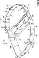
- figure 3 shows a perspective view of an embodiment of such a mounting frame 20, which is used here, for example, for positioning a battery 130, a capacitor 131 and a printed circuit board 132.
- the mounting frame 20 can be positioned in the interior 14 or in the first device housing shell 12, so that the mounting frame 20 can surround at least a portion of the interior 14.
- the mounting frame 20 can have a first edge 22 and rest with this on the bottom 16 of the shell 12 .
- the mounting frame 20 has, in particular, an opposite second edge 24 , a distance between the two edges 22 , 24 corresponding to a height 25 of the mounting frame 20 .
- the at least one electrical component 130, 131, 132 (in the figure 2 only the battery 130 is shown as an example) is preferably inserted into the mounting frame 20 in the mounting direction 110, ie perpendicular to the first plane 60 or to the floor 60.
- FIG 3 a perspective view of a mounting frame 20 according to the invention is shown.
- the mounting frame 20 can surround at least a partial area of the interior 14 of the device housing 10 and can be designed in such a way that it divides the interior 14 into a first area 140 , a second area 142 and a third area 144 .
- the second region 142 may be configured to enclose a printed circuit board.
- the first and third areas 140, 144 can each be designed to accommodate an electrical component 130, 131 (eg in the form of a battery 130 and a capacitor 131).
- the mounting frame 20 has at least one or more clamping structures 30, 31.
- the mounting frame 20 and said Clamp structures 30, 31 are further in the figures 4 , 5A , 5B , 6A and 6B shown in detail.
- the at least one clamping structure 30, 31 can be in the form of a rocker 30, for example.
- the at least one clamping structure 31 can be formed by a projection 31 of the mounting frame 20 .
- the mounting frame 20 according to figure 3 have a large number of clamping structures 30, 31, in particular at least one clamping structure 30 in the form of a rocker 30 and a plurality of clamping structures 31 in the form of a projection 31 of the mounting frame 20.
- the rocker 30 can be used to fix a battery 130, whereas the projections 31 can be used to fix a capacitor/capacitor stack 131.
- the mounting frame 20 according to 3 have exactly one rocker 30 and exactly six projections 31 of the mounting frame 40 .
- the rocker 30 can be arranged in a first section 26 of the mounting frame 20, which can form a boundary of the first region 140 of the interior 14, which can be used, for example, to accommodate an electrical component in the form of a battery 130.
- the projections 31 of the mounting frame 40 can be arranged in a second section 28 of the mounting frame 20 which can form a boundary of the third region 144 which can serve to accommodate an electrical component in the form of a capacitor/capacitor stack 130 .
- the projections 31 may be grouped in pairs on the second portion 28 of the frame 20 .
- the respective projection 31 of the mounting frame 20 preferably has a free end 42 , with the respective projection 31 tapering towards its end 41 . Furthermore, it is provided in particular that the projections 31 are each arranged in a recess 44 on the second edge 24 of the mounting frame 20 or protrude from the mounting frame 20 in the recess 44 . In this case, the projections 31 extend in particular before the component 131 in question is fixed in the mounting direction 110. As further from FIG 3 can be seen (cf. also 4 ),
- the rocker 30 preferably a first arm 52 and a second arm 54 projecting from the mounting frame 20 in different directions. The second arm 54 is preferably longer than the first arm 52 of the rocker 30.
- the first and the second arm 52, 54 of the rocker 30 preferably protrude from a web 70 which is formed by a first cutout 72 in the first edge 22 and by an opposite second cutout 74 in the second edge 24 of the mounting frame 20.
- the second recess 74 is opposite the first recess 72 in the direction of the assembly direction 110 .
- the distance between the first edge 22 and the web 70 can be smaller than the distance between the web 70 and the second edge 24 along the assembly direction 110 or perpendicular to the base 16.
- the clamping structures 30, 31 described above can each assume a first state and are designed to be converted into a second state for fixing the respective component 130, 131.
- FIG. 3 shows in this regard the clamping structures 30, 31 of the mounting frame 20 in the respective first state, arranging the components 130, 131 in the mounting frame 20 is possible.
- the respective projection 31 of the mounting frame 20 extends perpendicular to the first plane 60 or to the bottom 16 of the first device housing shell 12 on which the mounting frame 20 is arranged.
- the mounting direction 110 runs perpendicularly to the first plane 60 or to the floor 16, so that the respective projection 31 extends in the mounting direction 110.
- the free end 42 of the respective projection 31 can protrude perpendicularly to the first plane 60 or to the floor 16 beyond the second edge 24 of the mounting frame 20 .
- the second arm 54 of the at least one rocker 30 can also extend perpendicularly to the floor 16 (along the mounting direction 110) beyond the second edge 24 of the mounting frame 20.
- the at least one rocker 30 can be configured such that the second arm 54 extends perpendicularly to the floor 16 or to the first plane 60 when the rocker is in the first state.
- This orientation of the rocker 30 (the same applies to the projections 31) allows the relevant electrical component (here, for example, the battery 130) to be arranged in the mounting frame 20 along the mounting direction 110.
- the respective clamping structure 30, 31 is also designed to be convertible from the respective first state into a second state.
- This is eg in the figures 4 , 5A , 5B , 6A and 6B illustrated.
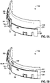
- the first and the second state of the at least one rocker 30 are shown.
- the Figures 6A and 6B represent the first and the second state for the case of a clamping structure 31 in the form of a projection 31.
- the first arm 52 is preferably arranged on the web 70 at an obtuse angle 120 to the second arm 52, with the first arm 52 of the rocker 30 in the first state of the rocker 30 protruding parallel to the floor 16 further into the interior space 14 than the second arm 54.
- the rocker 30 can be tilted about a tilting axis which can extend in particular along the direction of longitudinal extent or longitudinal axis of web 70 .
- the mounting frame 20 shown can also have one or more ribs 90 with the help of which the electrical component 130 can be fixed parallel to the first plane 60 or parallel to the bottom 16 of the first device housing shell 12 in the device housing 10 .
- the Figures 6A and 6B each show a detail cross section through a device housing 10 of an implantable medical device 1 in the open state ( Figure 6A ) and in the closed state ( Figure 6B ) and thereby illustrate the functioning of the respective clamping structure 31 when this is in the form of a projection 31 of the mounting frame 20. while showing Figure 6A a projection 31 in the first state during Figure 6B shows the projection 31 in the second state.
- the electrical component 130 can already be arranged in the mounting frame 20 , ie it can be located in the interior 14 of the device housing 10 of the implant 1 .
- the respective projection 31 extends along the mounting direction 110.
- the second device housing shell 13 can now be moved in the mounting direction 110 to the first device housing shell 12 in order to be connected to it.
- the second device housing shell 13 presses against the end 42 of the respective projection 31 and deforms it in such a way that the respective projection presses against the electrical component and thus fixes it perpendicularly to the base 16 or to the first plane 60 in the device housing 10 .
- the respective projection 31 can be deformed in such a way that it rests against the electrical component 130 and exerts a force on the electrical component 130 that has a vector component 102 that runs along the assembly direction 110 or is perpendicular to the floor 16/first plane 60 oriented.
Landscapes
- Health & Medical Sciences (AREA)
- Engineering & Computer Science (AREA)
- Biomedical Technology (AREA)
- Nuclear Medicine, Radiotherapy & Molecular Imaging (AREA)
- Radiology & Medical Imaging (AREA)
- Life Sciences & Earth Sciences (AREA)
- Animal Behavior & Ethology (AREA)
- General Health & Medical Sciences (AREA)
- Public Health (AREA)
- Veterinary Medicine (AREA)
- Cardiology (AREA)
- Heart & Thoracic Surgery (AREA)
- Electrotherapy Devices (AREA)
Description
- Die Erfindung betrifft ein implantierbares medizinisches Gerät, insbesondere einen Kardioverter- Defibrillator.
- Implantierbare medizinisches Geräte, insbesondere Implantate zur Stimulation eines Organs und/oder zur Aufnahme eines physiologischen Signals (z.B. implantierbare Herzschrittmacher, Kardioverter-Defibrillatoren (ICD), Neurostimulatoren etc.), weisen in der Regel ein Gerätegehäuse auf, in dem zumindest eine elektrische Komponente angeordnet ist.
- Mithilfe eines derartigen ICDs kann der Herzrhythmus einer Person überwacht werden, wobei bei detektierten Unregelmäßigkeiten, insbesondere bei Kammerflimmern, Kammerflattern oder einer Tachykardie, ein elektrischer Impuls durch den ICD an das Herz abgegeben werden kann, durch den ein normaler Herzrhythmus wieder hergestellt werden kann.
- Für eine uneingeschränkte Funktion solcher implantierbaren medizinischen Geräte muss insbesondere eine Verbindung zwischen einer Leiterplatte/Schaltkreis und einer elektrischen Komponente (z.B. Batterie oder Kondensator) des Gerätes bestehen, die auch bei einer Bewegung des implantierbaren medizinischen Gerätes intakt bleibt. Um dies zu erreichen, kann die elektrische Komponente im implantierbaren medizinischen Gerät fixiert werden. Der Begriff "Fixierung" meint dabei, dass eine Bewegung der Komponente bezüglich des Gerätegehäuses verhindert wird. Bei einer "vollständigen Fixierung" wird eine Bewegung einer Komponente in alle Raumrichtungen verhindert. Bei einer "unvollständigen Fixierung" kann sich eine Komponente zumindest in eine Raumrichtung bewegen. Ohne eine Fixierung oder bei einer unvollständigen Fixierung der Komponente kann sich die Komponente innerhalb des Gehäuses des implantierbaren medizinischen Gerätes bewegen, so dass z.B. die besagte Verbindung zwischen der Komponente und der Leiterplatte/Schaltkreis unterbrochen bzw. gestört werden kann. Dies kann einen Funktionsausfall zur Folge haben, wodurch es möglicherweise zu einem unerwünschten Therapieausfall kommen kann.
- Auch ist für den Herstellungsprozess eines implantierbaren medizinischen Geräts ist eine Fixierung von wesentlichen Komponenten innerhalb des Montagerahmens. Unter einem Montagerahmen wird im Allgemeinen ein Element verstanden, das dazu ausgelegt ist, Komponenten eines Gerätes zu fixieren. Ein Montagerahmen wird verwendet, um Herstellungsschritte zu vereinfachen und einen sicheren Transport von montierten Produkten und Zwischenprodukten zu gewährleisten.
- Zur Reduktion einer Bewegung einer Komponente im Inneren des Gerätes ist im Stand der Technik ein Montagerahmen bekannt, in den eine Komponente positioniert werden kann. Ein derartiger Montagerahmen kann sogenannte Rippen aufweisen, mit deren Hilfe die Komponente in einer ersten Ebene fixiert werden kann, d.h., dass die Bewegung der Komponente parallel zur ersten Ebene reduziert oder verhindert werden kann. Bei einer Positionierung der Komponente in einem solchen Montagerahmen kann sich die Komponente jedoch weiterhin senkrecht zur ersten Ebene bewegen. Eine vollständige Fixierung ist daher durch einen derartigen Montagerahmen nicht erreicht.
- Für eine Fixierung der Komponenten senkrecht zur ersten Ebene sind im Stand der Technik unterschiedliche Lösungen offenbart.
- Eine Lösung sieht eine zusätzliche Fixierung einer Komponente durch Kleben vor. Allerdings kann ein dabei verwendetes Klebematerial Alterungserscheinungen unterliegen, so dass die Fixierung mit zunehmendem Alter des implantierbaren medizinischen Gerätes an Wirksamkeit verlieren kann. Weiterhin würde bei einer derartigen Fixierung die Herstellungszeit des implantierbaren medizinischen Gerätes verlängert, da das Klebematerial aushärten muss, bevor ein weiterer Herstellungsschritt erfolgen kann. Weiterhin könnten Bestandteile des Klebematerials für Veränderungen anderer Komponenten des implantierbaren medizinischen Gerätes, insbesondere der Leiterplatte, sorgen. Insbesondere könnte es zu einer Korrosion kommen, durch die die Funktion der Leiterplatte und damit die Funktion des implantierbaren medizinischen Gerätes reduziert werden könnte.
- Nach dem Stand der Technik ist alternativ eine Lösung bekannt, die ein Pressen des implantierbaren medizinischen Gerätes umfasst. Dabei besteht jedoch unter Umständen das Risiko einer Beschädigung der Komponenten bzw. das Risiko, dass das Gehäuse nicht vollständig geschlossen wird.
- Eine andere Lösung weist ein zusätzliches Bauteil auf, wobei das zusätzliche Bauteil der Fixierung durch Ausgleich einer Toleranz dienen kann. Ein zusätzliches Bauteil kann beispielsweise eine zusätzliche Kunststofffolie oder ein Element aus Schaumstoff sein. Allerdings können durch zusätzliche Bauteile die Kosten der Herstellung des implantierbaren medizinischen Gerätes in unerwünschter Weise erhöht werden. Schließlich wird in der
WO 2015/106109 ein erster Rahmen offenbart, der Rückhalteelemente aufweist, durch die ein zweiter Rahmen, der im Inneren des ersten Rahmens positioniert ist, stabilisiert werden kann.US 2017/127543 ,US 5 814 090 ,US 2004/082977 undUS 5 873 899 zeigen weitere Ausführungen von Montagerahmen. - Hiervon ausgehend liegt der vorliegenden Erfindung die Aufgabe zugrunde, ein implantierbares medizinisches Gerät bereitzustellen, das eine elektrische Komponente aufweist, die auf einfache Weise sicher im Innenraum des Gerätegehäuses fixierbar ist. Weiterhin soll das implantierbare medizinische Gerät insbesondere so gestaltet sein, dass die Komponente auf einfache Weise im Innenraum des Gerätegehäuses anordbar ist.
- Diese Aufgabe wird durch ein implantierbares medizinisches Gerät mit den Merkmalen des Anspruchs 1 gelöst. Vorteilhafte Ausführungsformen sind in den Unteransprüchen angegeben und werden nachfolgend beschrieben.
- Gemäß Anspruch 1 wird ein implantierbares medizinisches Gerät offenbart, mit: einem Gerätegehäuse, das eine erste und eine zweite Gerätegehäuseschale aufweist, wobei das Gerätegehäuse einen Innenraum umgibt. Ferner weist das implantierbare medizinische Gerät eine elektrische Komponente des Gerätes auf, die im Innenraum angeordnet ist. Zudem weist das implantierbare medizinische Gerät einen Montagerahmen auf, der im Innenraum angeordnet ist und die elektrische Komponente umgibt. Dabei weist der Montagerahmen mindestens eine Klemmstruktur auf, wobei die mindestens eine Klemmstruktur dazu ausgebildet ist, eine Kraft auf die elektrische Komponente auszuüben, um die elektrische Komponente im Innenraum des Gerätegehäuses zu fixieren, wobei die mindestens eine Klemmstruktur als eine Wippe ausgebildet ist, wobei die Wippe zumindest einen ersten Arm und einen zweiten Arm aufweist, wobei der erste Arm und der zweite Arm in unterschiedliche Richtungen von einem durch den Montagerahmen gebildeten Steg abstehen.
- Ein implantierbares medizinisches Gerät wird im Folgenden auch kurz als Implantat bezeichnet.
- In einer Ausführungsform sind das Gerätegehäuse und der Montagerahmen dazu ausgebildet eine Leiterplatte und mindestens eine, insbesondere zwei, elektrische Komponenten zu umgeben bzw. aufzunehmen.
- Der Montagerahmen kann insbesondere einstückig ausgebildet sein. Der Montagerahmen kann dabei ein Material aufweisen oder aus einem Material gebildet sein, das Toleranzen der Bauteile des Implantats ausgleichen kann. Das Material kann ein elastisches Material sein. Insbesondere kann das Material eines der folgenden Materiale sein: Polybutylenterephthalat (PBTP, PBT), Liquid Crystal Polymer (LCP), Polyurethan (PU), Acrylnitril-Butadien-Styrol (ABS), Polysolfon (PSU), Polyetheretherketon (PEEK), Polyoxymethylen (POM), etc.
- Die erste und/oder die zweite Gerätegehäuseschale können beispielsweise eines der folgenden Materiale aufweisen oder durch eines der folgenden Materialien gebildet sein: Titan, oder eine Titanlegierung (biokompatibel).
- Der Montagerahmen kann des Weiteren in der ersten und/oder der zweiten Gerätegehäuseschale angeordnet sein.
- In einer Ausführungsform der Erfindung ist die mindestens eine Klemmstruktur dazu ausgebildet, mindestens einen ersten und einen zweiten Zustand einzunehmen, wobei im ersten Zustand keine Kraft durch die mindestens eine Klemmstruktur auf die elektrische Komponente ausgeübt wird, und wobei im zweitem Zustand eine Kraft durch die mindestens eine Klemmstruktur auf die elektrische Komponente ausgeübt wird, um die Komponente im Innenraum des Gerätegehäuses zu fixieren.
- Ferner kann die mindestens eine Klemmstruktur dazu ausgebildet und derart positioniert sein, dass durch die Klemmstruktur im ersten Zustand die Anordnung bzw. Montage der elektrischen Komponente im Montagerahmen nicht gestört und/oder verhindert wird.
- Die Anordnung bzw. Montage kann insbesondere entlang einer Montagerichtung durchgeführt werden, d.h. die elektrische Komponente kann entlang einer Montagerichtung in dem Montagerahmen angeordnet werden bzw. in diesen eingesetzt werden.
- Gemäß einer weiteren Ausführungsform der Erfindung ist die mindestens eine Klemmstruktur dazu ausgebildet, vom ersten Zustand in den zweiten Zustand überführt zu werden, wenn die elektrische Komponente in dem Montagerahmen angeordnet wird.
- Das bedeutet, dass für die Überführung der mindestens einen Klemmstruktur vom ersten Zustand in den zweiten Zustand kein zusätzlicher Herstellungsschritt bei der Herstellung des Implantates benötigt wird, da durch die Anordnung der elektrischen Komponente in dem Montagerahmen die elektrische Komponente vom ersten in den zweiten Zustand überführt und die elektrischen Komponente im Innenraum fixiert werden kann.
- In einer alternativen Ausführungsform ist die mindestens eine Klemmstruktur dazu ausgebildet vom ersten Zustand in den zweiten Zustand überführt zu werden, wenn das Gerätegehäuse durch Zusammensetzen der ersten und der zweiten Gerätegehäuseschale geschlossen wird.
- Durch das Schließen des Gerätegehäuses kann die elektrische Komponente vom ersten in den zweiten Zustand überführt und die elektrischen Komponente im Innenraum fixiert werden, so dass die Überführung vom ersten Zustand in den zweiten Zustand ein zusätzliches Resultat eines Herstellungsschrittes des Implantates ist, der in jedem Falle durchgeführt werden muss. Das bedeutet, dass für die Überführung vom ersten Zustand in den zweiten Zustand, d.h. für das Fixieren der elektrischen Komponente, kein zusätzlicher Herstellungs- bzw. Verfahrensschritt durchgeführt werden muss.
- Gemäß einer weiteren Ausführungsform der Erfindung ist vorgesehen, dass die erste Gerätegehäuseschale einen Boden sowie vorzugsweise eine davon abgehende umlaufende Wandung aufweist. Weiterhin ist gemäß einer Ausführungsform der Erfindung vorgesehen, dass die zweite Gerätegehäuseschale einen Boden sowie vorzugsweise eine davon abgehende umlaufende Wandung aufweist.
- Der Boden der ersten Gerätegehäuseschale kann sich dabei in bzw. entlang einer ersten Ebene erstrecken. In gleicher Weise kann sich der Boden der zweiten Gerätegehäuseschale kann in bzw. entlang einer zweiten Ebene erstrecken.
- Bei einem geschlossenen Gerätegehäuse können sich somit die erste Ebene und die zweite Ebene parallel zueinander erstrecken, d.h., der Boden der ersten Gerätegehäuseschale kann parallel zum Boden der zweiten Gerätegehäuseschale verlaufen. Die jeweilige Gerätegehäuseschale kann insbesondere einstückig ausgebildet sein.
- Denkbar sind ebenfalls abgerundete Formen eines Gerätegehäuses, deren Gehäuseschalen keine planen Ebenen aufweisen.
- Der Boden der ersten und/oder der zweiten Gerätegehäuseschale und der Montagerahmen können so konfiguriert sein, dass der Montagerahmen im Innenraum auf dem Boden der ersten und/oder der zweiten Gerätegehäuseschale anordenbar ist. Insbesondere kann der Montagerahmen so in der ersten und/oder der zweiten Gerätegehäuseschale anordenbar bzw. angeordnet sein, dass eine elektrische Komponente entlang einer Montagerichtung, die senkrecht zu dem besagten Boden verläuft, in dem Montagerahmen angeordnet werden kann.
- Die mindestens eine Klemmstruktur kann dazu ausgebildet sein, eine Kraft auf die elektrische Komponente auszuüben, die zumindest eine Vektorkomponente aufweist, die sich senkrecht zum Boden der ersten oder zweiten Gerätegehäuseschale erstreckt. Das bedeutet, dass die elektrische Komponente mithilfe der mindestens einen Klemmstruktur insbesondere senkrecht zu dem besagten Boden des Gerätegehäuses fixiert werden kann. Weiterhin ist gemäß einer Ausführungsform des implantierbaren medizinischen Gerätes
- vorgesehen, dass mindestens eine weitere Klemmstruktur vorgesehen ist, wobei die mindestens eine weitere Klemmstruktur als ein Vorsprung des Montagerahmens ausgebildet ist, wobei sich der Vorsprung des Montagerahmens im ersten Zustand der mindestens einen Klemmstruktur senkrecht zum Boden der ersten Gerätegehäuseschale oder senkrecht zum Boden der zweiten Gerätegehäuseschale erstreckt.
- Der Vorsprung kann sich dabei im ersten Zustand entlang der Montagerichtung erstrecken, die senkrecht zum Boden der ersten oder der zweiten Gerätegehäuseschale verläuft (siehe oben). Die elektrische Komponente kann daher leicht entlang der Montagerichtung in dem Montagerahmen angeordnet werden, ohne dass die mindestens eine Klemmstruktur bzw. der mindestens eine Vorsprung die Montage beeinträchtigt und/oder verhindert.
- Weiterhin ist gemäß einer Ausführungsform der Erfindung vorgesehen, dass der Vorsprung des Montagerahmens ein freies Ende aufweist, wobei sich der Vorsprung des Montagerahmens zu diesem Ende hin verjüngt.
- Gemäß einer Ausführungsform der Erfindung ist weiterhin vorgesehen, dass zumindest ein Bereich der mindestens einen Klemmstruktur (z.B. des Vorsprungs oder der Wippe, siehe unten) deformierbar ausgebildet ist. Durch eine Deformation dieses Bereiches der jeweiligen Klemmstruktur ist die betreffende Klemmstruktur von ihrem ersten Zustand in ihren zweiten Zustand überführbar.
- In einer Ausführungsform der Erfindung ist die mindestens eine Klemmstruktur bzw. der mindestens eine Vorsprung durch das Schließen des Gerätegehäuses, d.h., durch das bestimmungsgemäße Verbinden der beiden Gerätegehäuseschalen, deformierbar, so dass die mindestens eine Klemmstruktur (z.B. Vorsprung) vom ersten Zustand in den zweiten Zustand überführt wird, in dem die mindestens eine Klemmstruktur die Komponente im Innenraum des Gerätegehäuses fixiert.
- Für den Fall, dass der Montagerahmen und die elektrische Komponente bei der Montage in der ersten Gerätegehäuseschale angeordnet werden, kann der mindestens eine Vorsprung des Montagerahmens senkrecht zum Boden der ersten Gerätegehäuseschale über deren Wandung hinausragen, wobei die zweite Gerätegehäuseschale insbesondere dazu ausgebildet sein kann, beim Verbinden mit der ersten Gerätegehäuseschale gegen den mindestens einen Vorsprung zu drücken, so dass dieser vom ersten in den zweiten Zustand überführt wird. Alternativ hierzu kann der Montagerahmen bzw. die Komponente zunächst auch in der zweiten Gerätegehäuseschale angeordnet werden, wobei das Fixieren dann durch Verbinden der ersten Gerätegehäuseschale mit der zweiten Gerätegehäuseschale erfolgt, in der der Rahmen und die Komponente ruhen.
- Der Umstand, dass zumindest ein Bereich der jeweiligen Klemmstruktur deformierbar ist, um die Klemmstruktur vom ersten in den zweiten Zustand zu überführen, kann insbesondere auch bedeuten, dass ein anderer Bereich der betreffenden Klemmstruktur vorliegen kann, der bei der Überführung vom ersten in den zweiten Zustand nicht deformiert wird, also mit anderen Wort bei der Überführung seine Form behält.
- So kann z.B. gemäß einer weiteren Ausführungsform der Erfindung vorgesehen sein, dass die mindestens eine Klemmstruktur im zweiten Zustand in Richtung auf den Boden der ersten oder zweiten Gerätegehäuseschale geneigt sein kann und dabei gegen die elektrische Komponente drückt, um die besagte Kraft auf die elektrische Komponente auszuüben und diese im Innenraum des Gerätegehäuses zu fixieren. Die Klemmstruktur kann z.B. im zweiten Zustand in Richtung des Bodens der ersten Gerätegehäuseschale geneigt sein, wenn der Montagerahmen bei der Montage zunächst in der ersten Gerätegehäuseschale angeordnet ist. Für den Fall, dass der Montagerahmen bei der Montage zunächst in der zweiten Gerätegehäuseschale angeordnet wird, kann die Klemmstruktur im zweiten Zustand in Richtung des Bodens der zweiten Gerätegehäuseschale geneigt sein Insbesondere kann die Klemmstruktur wiederum im zweiten Zustand mit einer Kraft gegen die Komponente drücken, die eine Vektorkomponente aufweist, die senkrecht zum Boden der ersten oder der zweiten Gerätegehäuseschale verläuft, so dass die Klemmstruktur die elektrische Komponente senkrecht zum betreffenden Boden des Gerätegehäuses fixieren kann.
- Dass die Klemmstruktur im zweiten Zustand in Richtung des Bodens der ersten oder der zweiten Gerätegehäuseschale geneigt sein kann bedeutet insbesondere, dass sich der Vorsprung unter einem spitzen Winkel zum Boden der ersten oder zweiten Gerätegehäuseschale erstreckt. Entsprechend kann ein Abstand zwischen dem Ende des Vorsprungs und dem Boden der ersten oder der zweiten Gerätegehäuseschale im zweiten Zustand geringer sein als im ersten Zustand.
- der Erfindung ist vorgesehen, dass die mindestens eine Klemmstruktur als eine Wippe ausgebildet ist. Dabei weist die Wippe zumindest einen ersten und einen zweiten Arm auf, wobei der erste Arm und der zweite Arm in unterschiedliche Richtungen von einem durch den Montagerahmen gebildeten Steg abstehen.
- Gemäß einer Ausführungsform der Erfindung können der Montagerahmen und die Wippe einstückig ausgebildet sein, d.h., aus einem Stück gefertigt sein (z.B. durch einen Formgebungsprozess wie z.B. Spritzgießen). Es ist auch denkbar, den Montagerahmen und die Wippe getrennt voneinander zu fertigen und anschließend miteinander zu verbinden. Gemäß einer Ausführungsform der Erfindung kann weiterhin vorgesehen sein, dass der erste und der zweite Arm in einer Ebene von dem Steg abstehen, die sich senkrecht zu einer Längserstreckungsrichtung des Steges und insbesondere senkrecht zum Boden der ersten oder zweiten Gerätegehäuseschale erstreckt. Die Längserstreckungsrichtung bzw. Längsachse des Steges kann entlang einer Umfangsrichtung des Montagerahmens verlaufen entlang der Montagerahmen umläuft.
- Gemäß einer weiteren Ausführungsform der Erfindung ist vorgesehen, dass sich der erste Arm der Wippe im ersten Zustand der Wippe geneigt zum Boden der ersten oder der zweiten Gerätegehäuseschale erstreckt und/oder dass sich der zweite Arm der Wippe im ersten Zustand der Wippe senkrecht zum Boden der ersten oder der zweiten Gerätegehäuseschale erstreckt.
- Der erste Arm und der zweite Arm der Wipp/Klemmstruktur können winklig zueinander angeordnet sein. Ein entsprechend zwischen den beiden Armen gebildeter Winkel kann ein stumpfer Winkel zwischen 90° und 175° sein, der insbesondere zwischen 100° und 170°, insbesondere zwischen 110° und 160° liegt. Insbesondere kann der Winkel 150° betragen.
- Im ersten Zustand der Wippe kann sich z.B. der zweite Arm senkrecht oder in einem Winkel größer als 90° zum Boden der ersten Gerätegehäuseschale erstrecken, so dass die elektrische Komponente entlang der Montagerichtung montiert werden kann, d.h., in den in der ersten Gerätegehäuseschale angeordneten Montagerahmen angeordnet werden kann, ohne mit dem zweiten Arm zu kollidieren. Das heißt, dass der zweite Arm eine Anordnung der elektrischen Komponente in den Montagerahmen bzw. in den Innenraum des Gerätegehäuses weder erschwert noch verhindert.
- Weiterhin ist gemäß einer Ausführungsform der Erfindung vorgesehen, dass der zweite Arm der Wippe länger ist als der erste Arm der Wippe.
- Weiterhin ist gemäß einer Ausführungsform der Erfindung vorgesehen, dass die mindestens eine im ersten Zustand befindliche Klemmstruktur bzw. Wippe durch eine Kraftausübung auf den ersten Arm in den zweiten Zustand kippbar ist. Die Klemmstruktur bzw. Wippe kann um eine Kippachse, die entlang der Längserstreckungsrichtung des Steges verlaufen kann, gekippt werden, wobei der Steg beim Kippen der Wippe/Klemmstruktur deformiert wird. Insbesondere ist vorgesehen, dass die Wippe durch Ausüben einer Kraft auf den ersten Arm vom ersten in den zweiten Zustand kippbar ist, wobei jene Kraft eine Vektorkomponente aufweist, die senkrecht zum Boden der ersten oder der zweiten Gerätegehäuseschale verläuft. Insbesondere kann der Montagerahmen so ausgebildet sein, dass die Klemmstruktur bzw. Wippe vom ersten in den zweiten Zustand kippt, wenn die elektrische Komponente im Montagerahmen angeordnet wird. Das heißt mit anderen Worten, dass über die elektrische Komponente jene Kraft auf den ersten Arm der Wippe ausgeübt wird, wenn die Komponente in den z.B. in der ersten Gerätegehäuseschale ruhenden Montagerahmen eingeführt wird und dabei in der Montagerichtung gegen den ersten Arm der Wippe drückt, so dass diese in den fixierenden zweiten Zustand gekippt wird, in dem der zweite Arm der Wippe gehen die Komponente drückt und diese im Innenraum bzw. im Montagerahmen fixiert. Im zweiten Zustand kann sich dabei der zweite Arm der Wippe geneigt zum Boden der ersten Gerätegehäuseschale erstrecken. Der erste Arm kann sich im zweiten Zustand senkrecht oder geneigt zum Boden der ersten Gerätegehäuseschale erstrecken.
- Insbesondere ist gemäß einer Ausführungsform der Erfindung vorgesehen, dass der zweite Arm der Wippe im zweiten Zustand der Wippe gegen die elektrische Komponente mit einer Kraft drückt, die eine Vektorkomponente senkrecht zum Boden der ersten Gerätegehäuseschale aufweist.
- Weiterhin ist gemäß einer Ausführungsform der Erfindung vorgesehen, dass der Montagerahmen einen ersten und einen gegenüberliegenden zweiten Rand aufweist. Dabei kann der Steg zwischen einer Aussparung des Montagerahmens am ersten Rand und einer gegenüberliegenden Aussparung des Montagerahmens am zweiten Rand verlaufen. Der Steg kann also mit anderen Worten als Verengung des Montagerahmens ausgebildet sein.
- Grundsätzlich kann gemäß einer weiteren Ausführungsform der Erfindung vorgesehen sein, dass der Montagerahmen eine weitere Klemmstruktur oder eine Vielzahl an Klemmstrukturen aufweist. Bei der jeweiligen Klemmstruktur kann es sich um einen Vorsprung des Montagerahmens handeln, der wiederum gemäß den hierin beschriebenen Ausführungsformen ausgebildet sein. Weiterhin kann es sich bei der jeweiligen Klemmstruktur um eine hierin beschriebene Wippe handeln. Eine Kombination von Vorsprüngen des Montagerahmens und Wippen ist ebenfalls denkbar.
- Einzelne Klemmstrukturen der Vielzahl an Klemmstrukturen können an unterschiedlichen Positionen entlang der Umfangsrichtung des Montagerahmens positioniert sein. Zwischen einer ersten Klemmstruktur und einer zweiten Klemmstruktur kann ein Abstand bestehen, der sich von einem Abstand zwischen der zweiten Klemmstruktur und einer dritten Klemmstruktur unterscheidet. In einer alternativen Ausführungsform kann der Abstand zwischen je zwei in Umfangsrichtung benachbarten Klemmstrukturen äquidistant sein.
- Eine Fixierung der elektrischen Komponente durch eine Vielzahl an Klemmstrukturen (z.B. Vorsprünge und/oder Wippen) kann insoweit von Vorteil sein, da hier die fixierende Kraft auf eine Vielzahl an Klemmstrukturen bzw. auf eine Vielzahl an Kontaktstellen zur elektrischen Komponente verteilt ist. Eine fehlerhafte Funktion einer individuellen Klemmstruktur kann entsprechend durch eine oder mehrere andere Klemmstrukturen kompensiert werden.
- Ferner können durch mehrere Klemmstrukturen auf einfache Weise mehrere elektrische Komponenten des Implantats im Innenraum des Gerätegehäuses bzw. im Montagerahmen fixiert werden. In einer Ausführungsform kann jeweils zumindest eine Klemmstruktur eine Kraft auf jeweils eine zugeordnete elektrische Komponente ausüben.
- Weiterhin ist der Erfindung vorgesehen, dass die mindestens eine elektrische Komponente des Implantats eine Batterie, ein Kondensator oder eine Kondensatoranordnung ist (z.B. ein Kondensatorstapel). Die Batterie kann insbesondere Energie für den Betrieb des medizinischen Implantates liefern. Der Kondensator kann insbesondere der Bereitstellung von elektrischen Impulsen zur Herstellung des normalen Herzrhythmus (Defibrillationsenergie) dienen.
- Weitere Merkmale und Vorteile der Erfindung werden nachfolgend anhand der Figurenbeschreibung von Ausführungsbeispielen erläutert. Es zeigen:
- Fig. 1
- einen Querschnitt einer ersten Gerätegehäuseschale mit darin angeordneten elektrischen Komponenten,
- Fig. 2
- einen Querschnitt einer ersten Gerätegehäuseschale mit darin angeordnetem Montagerahmen und Montagerichtung,
- Fig. 3
- eine perspektivische Ansicht eines Montagerahmens,
- Fig. 4
- einen Querschnitt einer Klemmstruktur in Form einer Wippe,
- Fig. 5A
- eine perspektivische Detailansicht eines Montagerahmens mit einer Wippe im ersten Zustand,
- Fig. 5B
- eine perspektivische Detailansicht eines Montagerahmens mit einer Wippe im zweiten Zustand,
- Fig. 6A
- eine Detailansicht eines Montagerahmens mit einem Vorsprung im ersten Zustand, und
- Fig. 6B
- eine Detailansicht eines Montagerahmens mit einem Vorsprung im zweiten Zustand.
-
Figur 1 zeigt einen schematischen Querschnitt durch eine erste Gerätegehäuseschale 12 eines Gerätegehäuses eines erfindungsgemäßen Implantats 1. Die erste Gerätegehäuseschale 12 kann einen Boden 16 und eine Wandung 18 aufweisen. Der Boden 16 der ersten Gerätegehäuseschale 12 kann sich in einer ersten Ebene 60 erstrecken. Die Wandung 18 kann insbesondere eine umlaufende Wandung 18 sein. - In der ersten Gerätegehäuseschale 12 ist zumindest eine elektrische Komponente 130, 131, 132 angeordnet.
Figur 1 zeigt diesbezüglich schematisch als Beispiel eine Leiterplatte 132 bzw. einen Schaltkreis 132 sowie weitere elektrische Komponenten 130, 131, bei denen es sich z.B. um eine Batterie 130 und einen Kondensator 131 handeln kann. Der Kondensator 131 kann in Form eines Kondensatorstapels 131 vorliegen. Die Leiterplatte 132 kann zwischen den beiden weiteren elektrischen Komponenten 130, 131 positioniert sein. - Die elektrischen Komponenten 130, 131, 132 können entlang einer Montagerichtung 110, illustriert durch den Pfeil in
Fig. 1 , in die erste Gerätegehäuseschale 12 eingebracht werden. Die Montagerichtung 110 verläuft vorzugsweise senkrecht zur ersten Ebene 60 bzw. zum Boden 16 der Gerätegehäuseschale 12. Hiernach kann zur Ausbildung des Gerätegehäuses 10 eine zweite Gerätegehäuseschale 13 mit der ersten (hier unteren) Gerätegehäuseschale 12 verbunden werden. Die Komponenten 130, 131, 132 können mittels eines in derFigur 2 gezeigten Montagerahmens 20 im Innenraum 14 des Gerätegehäuse 10 fixiert werden. Ein solcher Montagerahmen 20 ist schematisch in derFigur 2 dargestellt.Figur 3 zeigt eine perspektivische Ansicht einer Ausführungsform eines solchen Montagerahmens 20, der hier beispielsweise zum Positionieren einer Batterie 130, eines Kondensators 131 sowie einer Leiterplatte 132 dient. - Gemäß
Figur 2 kann der Montagerahmen 20 im Innenraum 14 bzw. in der ersten Gerätegehäuseschale 12 positioniert sein, so dass der Montagerahmen 20 zumindest einen Teilbereich des Innenraumes 14 umgeben kann. Der Montagerahmen 20 kann einen ersten Rand 22 aufweisen und mit diesem auf dem Boden 16 der Schale 12 aufliegen. Der Montagerahmen 20 weist insbesondere einen gegenüberliegenden zweiten Rand 24 auf, wobei eine Distanz zwischen den beiden Rändern 22, 24 einer Höhe 25 des Montagerahmens 20 entspricht. Die mindestens eine elektrischen Komponente 130, 131, 132 (in derFigur 2 ist exemplarisch nur die Batterie 130 dargestellt) wird vorzugsweise in Montagerichtung 110, d.h., senkrecht zur ersten Ebene 60 bzw. zum Boden 60 in den Montagerahmen 20 eingesetzt. - In
Figur 3 ist eine perspektivische Ansicht eines erfindungsgemäßen Montagerahmens 20 gezeigt. Der Montagerahmen 20 kann zumindest einen Teilbereich des Innenraumes 14 des Gerätegehäuses 10 umgeben und kann dabei so gestaltet sein, dass er den Innenraum 14 in einen ersten Bereich 140, einen zweiten Bereich 142 und einen dritten Bereich 144 unterteilt. Der zweite Bereich 142 kann dazu ausgebildet sein, eine Leiterplatte zu umgeben. Der erste und der dritte Bereich 140, 144 können zur Aufnahme je einer elektrischen Komponente 130, 131 ausgebildet sein (z.B. in Form einer Batterie 130 und eines Kondensators 131). - Es ist vorgesehen, dass der Montagerahmen 20 zumindest eine oder mehrere Klemmstrukturen 30, 31 aufweist. Der Montagerahmen 20 und die besagten Klemmstrukturen 30, 31 sind des Weiteren in den
Figuren 4 ,5A ,5B ,6A und 6B detailliert dargestellt. - Die mindestens eine Klemmstruktur 30, 31 kann z.B. in Form einer Wippe 30 ausgebildet sein. In einem alternativen Beispiel kann die mindestens eine Klemmstruktur 31 durch einen Vorsprung 31 des Montagerahmens 20 ausgebildet sein.
- Insbesondere kann der Montagerahmen 20 gemäß
Figur 3 eine Vielzahl an Klemmstrukturen 30, 31 aufweisen, und zwar insbesondere zumindest eine Klemmstruktur 30 in Form einer Wippe 30 sowie mehrere Klemmstrukturen 31 in Form je eines Vorsprungs 31 des Montagerahmens 20. Hierbei kann die Wippe 30 zum Fixieren einer Batterie 130 dienen, wohingegen die Vorsprünge 31 zum Fixieren eines Kondensators/Kondensatorstapels 131 verwendet werden können. - Insbesondere kann der Montagerahmen 20 gemäß
Fig. 3 genau eine Wippe 30 und genau sechs Vorsprünge 31 des Montagerahmens 40 aufweisen. Die Wippe 30 kann dabei in einem ersten Abschnitt 26 des Montagerahmens 20 angeordnet sein, der eine Begrenzung des ersten Bereiches 140 des Innenraums 14 bilden kann, der z.B. zur Aufnahme einer elektrischen Komponente in Form einer Batterie 130 dienen kann. Weiterhin können die Vorsprünge 31 des Montagerahmens 40 in einem zweiten Abschnitt 28 des Montagerahmens 20 angeordnet sein, der eine Begrenzung des dritten Bereiches 144 bilden kann, der zur Aufnahme einer elektrischen Komponente in Form eines Kondensators/Kondensatorstapels 130 dienen kann. Die Vorsprünge 31 können paarweise am zweiten Abschnitt 28 des Rahmens 20 gruppiert sein. - Vorzugsweise weist der jeweilige Vorsprung 31 des Montagerahmens 20 ein freies Ende 42 auf, wobei sich der jeweilige Vorsprung 31 zu seinem Ende 41 hin verjüngt. Weiterhin ist insbesondere vorgesehen, dass die Vorsprünge 31 jeweils in einer Aussparung 44 am zweiten Rand 24 des Montagerahmens 20 angeordnet sind bzw. in der Aussparung 44 vom Montagerahmen 20 abstehen. Hierbei erststrecken sich die Vorsprünge 31 insbesondere vor dem Fixieren der betreffenden Komponente 131 in der Montagerichtung 110. Wie weiterhin aus
Fig. 3 ersichtlich ist (vgl. auchFig. 4 ), weist die Wippe 30 vorzugsweise einen ersten Arm 52 und einen zweiten Arm 54 auf, die in unterschiedliche Richtungen vom Montagrahmen 20 abstehen. Bevorzugt ist der zweite Arm 54 länger als der erste Arm 52 der Wippe 30. - Wie anhand der
Figuren 3 und4 ersichtlich ist, stehen der erste und der zweite Arm 52, 54 der Wippe 30 vorzugsweise von einem Steg 70 ab, der durch eine erste Aussparung 72 des ersten Randes 22 sowie durch eine gegenüberliegende zweite Aussparung 74 des zweiten Randes 24 des Montagerahmens 20 gebildet ist. Hierbei liegt die zweite Aussparung 74 der ersten Aussparung 72 in Richtung der Montagerichtung 110 gegenüber. Entlang der Montagerichtung 110 oder auch senkrecht zum Boden 16 kann der Abstand zwischen dem ersten Rand 22 und dem Steg 70 geringer sein als der Abstand zwischen dem Steg 70 und dem zweiten Rand 24. - Die oben beschriebenen Klemmstrukturen 30, 31 können jeweils einen ersten Zustand einnehmen und sind dazu ausgebildet zum Fixieren der jeweiligen Komponente 130, 131 in einen zweiten Zustand überführt zu werden.
-
Fig. 3 zeigt diesbezüglich die Klemmstrukturen 30, 31 des Montagerahmens 20 im jeweiligen ersten Zustand, wobei ein Anordnen der Komponenten 130, 131 im Montagerahmen 20 möglich ist. - Im ersten Zustand erstreckt sich der jeweilige Vorsprung 31 des Montagerahmens 20 senkrecht zur ersten Ebene 60 bzw. zum Boden 16 der ersten Gerätegehäuseschale 12 auf der der Montagerahmen 20 angeordnet ist. Die Montagerichtung 110 verläuft dabei senkrecht zur ersten Ebene 60 bzw. zum Boden 16, so dass sich der jeweilige Vorsprung 31 in der Montagerichtung 110 erstreckt. Das freie Ende 42 des jeweiligen Vorsprungs 31 kann dabei senkrecht zur ersten Ebene 60 bzw. zum Boden 16 über den zweiten Rand 24 des Montagerahmens 20 hinausragen.
- Wie weiterhin aus
Fig. 4 ersichtlich ist, kann sich auch der zweite Arm 54 der mindestens einen Wippe 30 senkrecht zum Boden 16 (entlang der Montagerichtung 110) über den zweiten Rand 24 des Montagerahmens 20 hinaus erstrecken. - Insbesondere kann die mindestens eine Wippe 30 so konfiguriert sein, dass sich der zweite Arm 54 senkrecht zum Boden 16 bzw. zur ersten Ebene 60 erstreckt, wenn sich die Wippe im ersten Zustand befindet. Durch diese Ausrichtung der Wippe 30 (gleiches gilt für die Vorsprünge 31) kann die betreffende elektrische Komponente (hier z.B. die Batterie 130) entlang der Montagerichtung 110 in dem Montagerahmen 20 angeordnet werden.
- Die jeweilige Klemmstruktur 30, 31 ist erfindungsgemäß weiterhin dazu ausgebildet, von dem jeweiligen ersten Zustand in einen zweiten Zustand überführbar zu sein. Dies ist z.B. in den
Figuren 4 ,5A ,5B ,6A und 6B illustriert. In denFiguren 4 ,5A und 5B sind der erste und der zweite Zustand der mindestens einen Wippe 30 gezeigt. DieFiguren 6A und 6B stellen den ersten und den zweiten Zustand für den Fall einer Klemmstruktur 31 in Form eines Vorsprungs 31 dar. -
Fig. 4 veranschaulicht im Zusammenhang mit denFiguren 5A und 5B das Funktionsprinzip der Wippe 30. Hierzu zeigt dieFig. 4 eine Schnittansicht der Wippe 30 entlang einer Ebene senkrecht zur Erstreckungsrichtung des Steges 70. Die im ersten Zustand befindliche Wippe 30 ist grob schraffiert dargestellt, wohingegen die im zweiten Zustand befindliche Wippe 30 in feinerer Schraffur gezeigt ist. - Vorzugsweise ist der erste Arm 52 unter einem stumpfen Winkel 120 zum zweiten Arm 52 am Steg 70 angeordnet, wobei der erste Arm 52 der Wippe 30 im ersten Zustand der Wippe 30 parallel zum Boden 16 weiter in den Innenraum 14 hineinragt als der zweite Arm 54.
- Hierdurch kann z. B. durch Anordnen der entsprechenden elektrischen Komponente 130 in den Montagerahmen 20 (vgl.
Fig. 5A ) eine Kraft 100 senkrecht zum Boden (in Richtung der Montagerichtung 110) auf den ersten Arm 52 ausgeübt werden, durch denn die Wippe 30 unter Deformation des Steges 70 vom ersten in den zweiten Zustand gekippt wird, wodurch weiterhin der zweite Arm 54 gegen die besagte Komponente 130 drückt und diese fixiert (vgl.Fig. 5B ). Das Kippen der Wippe 30 kann um eine Kippachse erfolgen, die sich insbesondere entlang der Längserstreckungsrichtung bzw. Längsachse des Steges 70 erstrecken kann. - Der in den
Figuren 4 ,5A und 5B gezeigte Montagerahmen 20 kann zudem eine oder mehrere Rippen 90 aufweisen, mit deren Hilfe die elektrische Komponente 130 parallel zur ersten Ebene 60 bzw. parallel zum Boden 16 der ersten Gerätegehäuseschale 12 im Gerätegehäuse 10 fixiert werden kann. - Die
Figuren 6A und 6B zeigen jeweils einen ausschnitthaften Querschnitt durch ein Gerätegehäuse 10 eines implantierbaren medizinischen Geräts 1 im geöffneten Zustand (Fig. 6A ) und im geschlossenen Zustand (Fig. 6B ) und illustrieren dabei die Funktionsweise der jeweiligen Klemmstruktur 31, wenn diese in Form eines Vorsprungs 31 des Montagerahmens 20 vorliegt. Dabei zeigtFig. 6A einen Vorsprung 31 im ersten Zustand währendFig. 6B den Vorsprung 31 im zweiten Zustand zeigt. In beiden Fällen kann die elektrische Komponente 130 bereits in dem Montagerahmen 20 angeordnet sein, sich also im Innenraum 14 des Gerätegehäuses 10 des Implantates 1 befinden. - Im ersten Zustand (
Fig. 6A ) erstreckt sich der jeweilige Vorsprung 31 entlang der Montagerichtung 110. Die zweite Gerätegehäuseschale 13 kann nun in der Montagerichtung 110 zur ersten Gerätegehäuseschale 12 hin bewegt werden, um mit dieser verbunden zu werden. Dabei drückt die zweite Gerätegehäuseschale 13 gegen das Ende 42 des jeweiligen Vorsprungs 31 und deformiert diesen derart, dass der jeweilige Vorsprung gegen die elektrische Komponente drückt und diese damit senkrecht zum Boden 16 bzw. zur ersten Ebene 60 im Gerätegehäuse 10 fixiert. Dies ist in derFigur 6B gezeigt. Der jeweilige Vorsprung 31 kann dabei so deformiert werden, dass er sich an die elektrische Komponente 130 anlegen und auf die elektrische Komponente 130 eine Kraft ausübt, die eine Vektorkomponente 102 aufweist, die entlang der Montagerichtung 110 verläuft bzw. senkreckt zum Boden 16/ersten Ebene 60 orientiert ist.
Claims (13)
- Implantierbares medizinisches Gerät (1), mit:- einem Gerätegehäuse (10) aufweisend eine erste Gerätegehäuseschale (12) und eine zweite Gerätegehäuseschale (13), wobei das Gerätegehäuse (10) einen Innenraum (14) umgibt,- einer elektrische Komponente des Gerätes (130, 131), die im Innenraum (14) angeordnet ist, wobei die elektrische Komponente (130) eine Batterie oder ein Kondensator ist,- einem Montagerahmen (20), der im Innenraum (14) angeordnet ist und die elektrische Komponente (130, 131) umgibt,wobei der Montagerahmen (20) mindestens eine Klemmstruktur (30, 31) aufweist, und wobei die mindestens eine Klemmstruktur (30, 31) dazu ausgebildet ist, eine Kraft (102) auf die elektrische Komponente (130) auszuüben, um die elektrische Komponente (130) im Innenraum des Gerätegehäuses (14) zu fixieren,
dadurch gekennzeichnet, dass
die mindestens eine Klemmstruktur (30) als eine Wippe ausgebildet ist, wobei die Wippe (30) zumindest einen ersten Arm (52) und einen zweiten Arm (54) aufweist, wobei der erste Arm (52) und der zweite Arm (54) in unterschiedliche Richtungen von einem durch den Montagerahmen (20) gebildeten Steg (70) abstehen.. - Implantierbares medizinisches Gerät (1) nach Anspruch 1, dadurch gekennzeichnet, dass die mindestens eine Klemmstruktur (30, 31) dazu ausgebildet ist, mindestens einen ersten und einen zweiten Zustand einzunehmen, wobei im ersten Zustand keine Kraft durch die mindestens eine Klemmstruktur (30, 31) auf die elektrische Komponente (130, 131) ausgeübt wird, und wobei im zweitem Zustand eine Kraft (102) durch die mindestens eine Klemmstruktur (30, 31) auf die elektrische Komponente (130, 131) ausgeübt wird, um die elektrische Komponente (130, 131) im Innenraum des Gerätegehäuses (14) zu fixieren.
- Implantierbares medizinisches Gerät (1) nach Anspruch 2, dadurch gekennzeichnet, dass die mindestens eine Klemmstruktur (30, 31) dazu ausgebildet ist, vom ersten Zustand in den zweiten Zustand überführt zu werden, wenn die elektrische Komponente (130) in dem Montagerahmen (20) angeordnet wird oder wenn das Gerätegehäuse (10) durch Zusammensetzen der ersten und der zweiten Gerätegehäuseschale (12, 13) geschlossen wird.
- Implantierbares medizinisches Gerät (1) nach einem der vorhergehenden Ansprüche, dadurch gekennzeichnet, dass die erste Gerätegehäuseschale (12) einen Boden (16) sowie eine davon abgehende umlaufende Wandung (18) aufweist; und/oder dass die zweite Gerätegehäuseschale (13) einen Boden (16) sowie eine davon abgehende umlaufende Wandung (18) aufweist.
- Implantierbares medizinisches Gerät (1) nach einem der Ansprüche 2 oder 3 und nach Anspruch 4, aufweisend mindestens eine weitere Klemmstruktur (31), wobei die mindestens die mindestens eine weitere Klemmstruktur (31) als ein Vorsprung des Montagerahmens (20) ausgebildet ist, wobei sich der Vorsprung des Montagerahmens (20) im ersten Zustand der mindestens einen Klemmstruktur (31) senkrecht zum Boden (16) der ersten Gerätegehäuseschale (12) oder senkrecht zum Boden (16) der zweiten Gerätegehäuseschale (13) erstreckt.
- Implantierbares medizinisches Gerät (1) nach Anspruch 5, dadurch gekennzeichnet, dass der Vorsprung (31) des Montagerahmens (20) ein Ende (42) aufweist, wobei sich der Vorsprung (31) des Montagerahmens (20) zum Ende (42) des Vorsprungs (31) hin verjüngt.
- Implantierbares medizinisches Gerät (1) nach einem der Ansprüche 5 oder 6, dadurch gekennzeichnet, dass zumindest ein Bereich (31, 70) der mindestens einen Klemmstruktur (30) oder der mindestens einen weiteren Klemmstruktur (31) deformierbar ist, so dass durch eine Deformation des mindestens einen Bereiches (31, 70) der mindestens einen Klemmstruktur (30) oder der mindestens einen weiteren Klemmstruktur (31) die mindestens einen Klemmstruktur (30) oder die mindestens eine weitere Klemmstruktur (31) vom ersten Zustand in den zweiten Zustand überführbar ist.
- Implantierbares medizinisches Gerät (1) nach einem der Ansprüche 5 bis 7, dadurch gekennzeichnet, dass die mindestens einen Klemmstruktur (30, 31) im zweiten Zustand in Richtung des Bodens (16) der ersten Gerätegehäuseschale (12) geneigt ist und dabei gegen die elektrische Komponente (130) drückt, um die besagte Kraft (102) auf die elektrische Komponente (130) auszuüben.
- Implantierbares medizinisches Gerät (1) nach Anspruch 1 und nach Anspruch 4, dadurch gekennzeichnet, dass der erste Arm (52) sich im ersten Zustand geneigt zum Boden (16) der ersten Gerätegehäuseschale (12) erstreckt und/oder dass sich der zweite Arm (54) im ersten Zustand senkrecht zum Boden (16) der ersten Gerätegehäuseschale (12) erstreckt.
- Implantierbares medizinisches Gerät (1) nach einem der vorherigen Ansprüche, dadurch gekennzeichnet, dass der zweite Arm (54) länger ist als der erste Arm (52).
- Implantierbares medizinisches Gerät (1) nach einem der vorherigen Ansprüche, dadurch gekennzeichnet, dass die mindestens eine im ersten Zustand befindliche Klemmstruktur (30) durch Ausüben einer Kraft (100) auf den ersten Arm (52) in den zweiten Zustand kippbar ist.
- Implantierbares medizinisches Gerät (1) nach einem der vorherigen Ansprüche, dadurch gekennzeichnet, dass der Montagerahmen (20) einen ersten Rand (22) und einen gegenüberliegenden zweiten Rand (24) aufweist, wobei der Steg (70) zwischen einer Aussparung des Montagerahmens am ersten Rand (72, 22) und einer gegenüberliegenden Aussparung des Montagerahmens am zweiten Rand (74, 24) verläuft.
- Implantierbares medizinisches Gerät (1) nach einem der vorhergehenden Ansprüche, dadurch gekennzeichnet, dass der Montagerahmen (20) eine weitere Klemmstruktur (30, 31) aufweist, wobei die weitere Klemmstruktur (30, 31) als ein weiterer Vorsprung (31) des Montagerahmens (20) ausgebildet ist, oder wobei die weitere Klemmstruktur als eine weitere Wippe ausgebildet ist, wobei insbesondere die weitere Wippe zumindest einen ersten und einen zweiten Arm aufweist, die insbesondere in unterschiedlichen Richtungen von einem durch den Montagerahmen gebildeten weiteren Steg abstehen.
Priority Applications (3)
| Application Number | Priority Date | Filing Date | Title |
|---|---|---|---|
| EP18194057.8A EP3623006B1 (de) | 2018-09-12 | 2018-09-12 | Fixierung von komponenten im innenraum eines implantierbaren medizinischen geräts mittels eines montagerahmens |
| US16/537,683 US11219776B2 (en) | 2018-09-12 | 2019-08-12 | Fixing of components in the interior of an implantable medical device by means of a mounting frame |
| SG10201907765TA SG10201907765TA (en) | 2018-09-12 | 2019-08-22 | Fixing of components in the interior of an implantable medical device by means of a mounting frame |
Applications Claiming Priority (1)
| Application Number | Priority Date | Filing Date | Title |
|---|---|---|---|
| EP18194057.8A EP3623006B1 (de) | 2018-09-12 | 2018-09-12 | Fixierung von komponenten im innenraum eines implantierbaren medizinischen geräts mittels eines montagerahmens |
Publications (2)
| Publication Number | Publication Date |
|---|---|
| EP3623006A1 EP3623006A1 (de) | 2020-03-18 |
| EP3623006B1 true EP3623006B1 (de) | 2022-07-27 |
Family
ID=63579076
Family Applications (1)
| Application Number | Title | Priority Date | Filing Date |
|---|---|---|---|
| EP18194057.8A Active EP3623006B1 (de) | 2018-09-12 | 2018-09-12 | Fixierung von komponenten im innenraum eines implantierbaren medizinischen geräts mittels eines montagerahmens |
Country Status (3)
| Country | Link |
|---|---|
| US (1) | US11219776B2 (de) |
| EP (1) | EP3623006B1 (de) |
| SG (1) | SG10201907765TA (de) |
Families Citing this family (2)
| Publication number | Priority date | Publication date | Assignee | Title |
|---|---|---|---|---|
| EP3881893A1 (de) * | 2020-03-17 | 2021-09-22 | BIOTRONIK SE & Co. KG | Implantierbarer impulsgenerator mit einer anordnung von zwei im winkel zueinander angeordneten komponenten |
| US12168136B2 (en) * | 2021-03-31 | 2024-12-17 | Vladimir Polic | Distributed defibrillator system to enable rapid response for cardiac or pulmonary arrest |
Family Cites Families (6)
| Publication number | Priority date | Publication date | Assignee | Title |
|---|---|---|---|---|
| US5814090A (en) * | 1995-06-07 | 1998-09-29 | Angeion Corporation | Implantable medical device having heat-shrink conforming shield |
| US5873899A (en) * | 1996-01-16 | 1999-02-23 | Pacesetter Inc. | Implantable medical device having compliant support for internal components |
| US6118652A (en) * | 1998-04-03 | 2000-09-12 | Medtronic, Inc. | Implantable medical device having flat electrolytic capacitor with laser welded cover |
| US6931284B2 (en) * | 2002-10-25 | 2005-08-16 | Medtronic, Inc. | Implantable medical device with air core antenna assembly |
| WO2015106109A1 (en) | 2014-01-10 | 2015-07-16 | Medtronic, Inc. | Frames for implantable medical devices and methods |
| US10772228B2 (en) * | 2015-11-03 | 2020-09-08 | Medtronic, Inc. | Sealed package including electronic device and power source |
-
2018
- 2018-09-12 EP EP18194057.8A patent/EP3623006B1/de active Active
-
2019
- 2019-08-12 US US16/537,683 patent/US11219776B2/en active Active
- 2019-08-22 SG SG10201907765TA patent/SG10201907765TA/en unknown
Also Published As
| Publication number | Publication date |
|---|---|
| EP3623006A1 (de) | 2020-03-18 |
| US11219776B2 (en) | 2022-01-11 |
| SG10201907765TA (en) | 2020-04-29 |
| US20200078597A1 (en) | 2020-03-12 |
Similar Documents
| Publication | Publication Date | Title |
|---|---|---|
| DE69309200T2 (de) | Flexible, flächige Kissenelektrode zur Einpflanzung unter einer Rippe | |
| DE69431730T2 (de) | Gebogenes, prothetisches netz, sowie verfahren zur herstellung | |
| EP3562442B1 (de) | Befestigungsanordnung einer prothesenhand an einem unterarmschaft und prothesensystem | |
| EP3714520B1 (de) | Kabeldurchführung | |
| DE3146182C2 (de) | Transvenös ins Herz einführbare Elektrodenanordnung für einen Herzschrittmacher | |
| EP3725366A1 (de) | Elektrisches kontaktbauteil | |
| DE68915655T2 (de) | Anschlussklemme zur Verbindung von Elektrodenkabeln mit einem Herzschrittmacher. | |
| DE60022570T2 (de) | Schnellsperrverbindungskopf für implantierbare medizinische Vorrichtung | |
| DE3712633A1 (de) | Steckverbindung fuer schrittmacher | |
| DE102010008360A1 (de) | Medizinisches Implantat, in welchem beim Crimpen bzw. Falten Lücken verbleiben, Verfahren und Einrichtung zum Verbringen | |
| DE60316237T2 (de) | Vorrichtung zur Verriegelung der Tür einer Waschmaschine | |
| BE1025075B1 (de) | Elektronikgehäuse zur Einhausung einer Elektronikkomponente | |
| DE3718913A1 (de) | Verbindungsanordnung | |
| DE69017979T2 (de) | Elektrischer Kontakt. | |
| DE4446711A1 (de) | Kathodenstrahlröhren-Anzeigevorrichtung | |
| EP3623006A1 (de) | Fixierung von komponenten im innenraum eines implantierbaren medizinischen geräts mittels eines montagerahmens | |
| DE202024101589U1 (de) | Einachsige Header-Baugruppe für ein Implantat | |
| DE19930238A1 (de) | Implantierbares elektronisches Gerät | |
| DE69323124T2 (de) | Vorrichtung zur selektiven Herstellung von elektrischen Verbindungen zwischen einer Reihe von Leitern | |
| DE2002425C3 (de) | Elektrischer Verbinder | |
| EP3473496B1 (de) | Haltevorrichtung und baugruppe mit einer haltevorrichtung | |
| DE4117303A1 (de) | Lenkrad | |
| EP4325676A1 (de) | Kabeldurchführungsvorrichtung | |
| DE3602674A1 (de) | Schnappriegelvorrichtung | |
| EP0466700B1 (de) | Webschaft mit lösbaren eckverbindungen |
Legal Events
| Date | Code | Title | Description |
|---|---|---|---|
| PUAI | Public reference made under article 153(3) epc to a published international application that has entered the european phase |
Free format text: ORIGINAL CODE: 0009012 |
|
| STAA | Information on the status of an ep patent application or granted ep patent |
Free format text: STATUS: THE APPLICATION HAS BEEN PUBLISHED |
|
| AK | Designated contracting states |
Kind code of ref document: A1 Designated state(s): AL AT BE BG CH CY CZ DE DK EE ES FI FR GB GR HR HU IE IS IT LI LT LU LV MC MK MT NL NO PL PT RO RS SE SI SK SM TR |
|
| AX | Request for extension of the european patent |
Extension state: BA ME |
|
| STAA | Information on the status of an ep patent application or granted ep patent |
Free format text: STATUS: REQUEST FOR EXAMINATION WAS MADE |
|
| 17P | Request for examination filed |
Effective date: 20200914 |
|
| RBV | Designated contracting states (corrected) |
Designated state(s): AL AT BE BG CH CY CZ DE DK EE ES FI FR GB GR HR HU IE IS IT LI LT LU LV MC MK MT NL NO PL PT RO RS SE SI SK SM TR |
|
| STAA | Information on the status of an ep patent application or granted ep patent |
Free format text: STATUS: EXAMINATION IS IN PROGRESS |
|
| 17Q | First examination report despatched |
Effective date: 20210208 |
|
| GRAP | Despatch of communication of intention to grant a patent |
Free format text: ORIGINAL CODE: EPIDOSNIGR1 |
|
| STAA | Information on the status of an ep patent application or granted ep patent |
Free format text: STATUS: GRANT OF PATENT IS INTENDED |
|
| RIC1 | Information provided on ipc code assigned before grant |
Ipc: A61N 1/378 20060101ALN20220201BHEP Ipc: A61N 1/375 20060101AFI20220201BHEP |
|
| INTG | Intention to grant announced |
Effective date: 20220222 |
|
| GRAS | Grant fee paid |
Free format text: ORIGINAL CODE: EPIDOSNIGR3 |
|
| GRAA | (expected) grant |
Free format text: ORIGINAL CODE: 0009210 |
|
| STAA | Information on the status of an ep patent application or granted ep patent |
Free format text: STATUS: THE PATENT HAS BEEN GRANTED |
|
| AK | Designated contracting states |
Kind code of ref document: B1 Designated state(s): AL AT BE BG CH CY CZ DE DK EE ES FI FR GB GR HR HU IE IS IT LI LT LU LV MC MK MT NL NO PL PT RO RS SE SI SK SM TR |
|
| REG | Reference to a national code |
Ref country code: CH Ref legal event code: EP |
|
| REG | Reference to a national code |
Ref country code: AT Ref legal event code: REF Ref document number: 1506674 Country of ref document: AT Kind code of ref document: T Effective date: 20220815 |
|
| REG | Reference to a national code |
Ref country code: DE Ref legal event code: R096 Ref document number: 502018010227 Country of ref document: DE |
|
| REG | Reference to a national code |
Ref country code: IE Ref legal event code: FG4D Free format text: LANGUAGE OF EP DOCUMENT: GERMAN |
|
| REG | Reference to a national code |
Ref country code: LT Ref legal event code: MG9D |
|
| REG | Reference to a national code |
Ref country code: NL Ref legal event code: MP Effective date: 20220727 |
|
| PG25 | Lapsed in a contracting state [announced via postgrant information from national office to epo] |
Ref country code: SE Free format text: LAPSE BECAUSE OF FAILURE TO SUBMIT A TRANSLATION OF THE DESCRIPTION OR TO PAY THE FEE WITHIN THE PRESCRIBED TIME-LIMIT Effective date: 20220727 Ref country code: RS Free format text: LAPSE BECAUSE OF FAILURE TO SUBMIT A TRANSLATION OF THE DESCRIPTION OR TO PAY THE FEE WITHIN THE PRESCRIBED TIME-LIMIT Effective date: 20220727 Ref country code: PT Free format text: LAPSE BECAUSE OF FAILURE TO SUBMIT A TRANSLATION OF THE DESCRIPTION OR TO PAY THE FEE WITHIN THE PRESCRIBED TIME-LIMIT Effective date: 20221128 Ref country code: NO Free format text: LAPSE BECAUSE OF FAILURE TO SUBMIT A TRANSLATION OF THE DESCRIPTION OR TO PAY THE FEE WITHIN THE PRESCRIBED TIME-LIMIT Effective date: 20221027 Ref country code: NL Free format text: LAPSE BECAUSE OF FAILURE TO SUBMIT A TRANSLATION OF THE DESCRIPTION OR TO PAY THE FEE WITHIN THE PRESCRIBED TIME-LIMIT Effective date: 20220727 Ref country code: LV Free format text: LAPSE BECAUSE OF FAILURE TO SUBMIT A TRANSLATION OF THE DESCRIPTION OR TO PAY THE FEE WITHIN THE PRESCRIBED TIME-LIMIT Effective date: 20220727 Ref country code: LT Free format text: LAPSE BECAUSE OF FAILURE TO SUBMIT A TRANSLATION OF THE DESCRIPTION OR TO PAY THE FEE WITHIN THE PRESCRIBED TIME-LIMIT Effective date: 20220727 Ref country code: FI Free format text: LAPSE BECAUSE OF FAILURE TO SUBMIT A TRANSLATION OF THE DESCRIPTION OR TO PAY THE FEE WITHIN THE PRESCRIBED TIME-LIMIT Effective date: 20220727 Ref country code: ES Free format text: LAPSE BECAUSE OF FAILURE TO SUBMIT A TRANSLATION OF THE DESCRIPTION OR TO PAY THE FEE WITHIN THE PRESCRIBED TIME-LIMIT Effective date: 20220727 |
|
| PG25 | Lapsed in a contracting state [announced via postgrant information from national office to epo] |
Ref country code: PL Free format text: LAPSE BECAUSE OF FAILURE TO SUBMIT A TRANSLATION OF THE DESCRIPTION OR TO PAY THE FEE WITHIN THE PRESCRIBED TIME-LIMIT Effective date: 20220727 Ref country code: IS Free format text: LAPSE BECAUSE OF FAILURE TO SUBMIT A TRANSLATION OF THE DESCRIPTION OR TO PAY THE FEE WITHIN THE PRESCRIBED TIME-LIMIT Effective date: 20221127 Ref country code: HR Free format text: LAPSE BECAUSE OF FAILURE TO SUBMIT A TRANSLATION OF THE DESCRIPTION OR TO PAY THE FEE WITHIN THE PRESCRIBED TIME-LIMIT Effective date: 20220727 Ref country code: GR Free format text: LAPSE BECAUSE OF FAILURE TO SUBMIT A TRANSLATION OF THE DESCRIPTION OR TO PAY THE FEE WITHIN THE PRESCRIBED TIME-LIMIT Effective date: 20221028 |
|
| PG25 | Lapsed in a contracting state [announced via postgrant information from national office to epo] |
Ref country code: SM Free format text: LAPSE BECAUSE OF FAILURE TO SUBMIT A TRANSLATION OF THE DESCRIPTION OR TO PAY THE FEE WITHIN THE PRESCRIBED TIME-LIMIT Effective date: 20220727 Ref country code: RO Free format text: LAPSE BECAUSE OF FAILURE TO SUBMIT A TRANSLATION OF THE DESCRIPTION OR TO PAY THE FEE WITHIN THE PRESCRIBED TIME-LIMIT Effective date: 20220727 Ref country code: MC Free format text: LAPSE BECAUSE OF FAILURE TO SUBMIT A TRANSLATION OF THE DESCRIPTION OR TO PAY THE FEE WITHIN THE PRESCRIBED TIME-LIMIT Effective date: 20220727 Ref country code: DK Free format text: LAPSE BECAUSE OF FAILURE TO SUBMIT A TRANSLATION OF THE DESCRIPTION OR TO PAY THE FEE WITHIN THE PRESCRIBED TIME-LIMIT Effective date: 20220727 Ref country code: CZ Free format text: LAPSE BECAUSE OF FAILURE TO SUBMIT A TRANSLATION OF THE DESCRIPTION OR TO PAY THE FEE WITHIN THE PRESCRIBED TIME-LIMIT Effective date: 20220727 |
|
| REG | Reference to a national code |
Ref country code: DE Ref legal event code: R097 Ref document number: 502018010227 Country of ref document: DE |
|
| REG | Reference to a national code |
Ref country code: BE Ref legal event code: MM Effective date: 20220930 |
|
| PG25 | Lapsed in a contracting state [announced via postgrant information from national office to epo] |
Ref country code: SK Free format text: LAPSE BECAUSE OF FAILURE TO SUBMIT A TRANSLATION OF THE DESCRIPTION OR TO PAY THE FEE WITHIN THE PRESCRIBED TIME-LIMIT Effective date: 20220727 Ref country code: EE Free format text: LAPSE BECAUSE OF FAILURE TO SUBMIT A TRANSLATION OF THE DESCRIPTION OR TO PAY THE FEE WITHIN THE PRESCRIBED TIME-LIMIT Effective date: 20220727 |
|
| PLBE | No opposition filed within time limit |
Free format text: ORIGINAL CODE: 0009261 |
|
| STAA | Information on the status of an ep patent application or granted ep patent |
Free format text: STATUS: NO OPPOSITION FILED WITHIN TIME LIMIT |
|
| GBPC | Gb: european patent ceased through non-payment of renewal fee |
Effective date: 20221027 |
|
| PG25 | Lapsed in a contracting state [announced via postgrant information from national office to epo] |
Ref country code: LU Free format text: LAPSE BECAUSE OF NON-PAYMENT OF DUE FEES Effective date: 20220912 Ref country code: AL Free format text: LAPSE BECAUSE OF FAILURE TO SUBMIT A TRANSLATION OF THE DESCRIPTION OR TO PAY THE FEE WITHIN THE PRESCRIBED TIME-LIMIT Effective date: 20220727 |
|
| 26N | No opposition filed |
Effective date: 20230502 |
|
| P01 | Opt-out of the competence of the unified patent court (upc) registered |
Effective date: 20230612 |
|
| PG25 | Lapsed in a contracting state [announced via postgrant information from national office to epo] |
Ref country code: FR Free format text: LAPSE BECAUSE OF NON-PAYMENT OF DUE FEES Effective date: 20220927 |
|
| PG25 | Lapsed in a contracting state [announced via postgrant information from national office to epo] |
Ref country code: SI Free format text: LAPSE BECAUSE OF FAILURE TO SUBMIT A TRANSLATION OF THE DESCRIPTION OR TO PAY THE FEE WITHIN THE PRESCRIBED TIME-LIMIT Effective date: 20220727 |
|
| PG25 | Lapsed in a contracting state [announced via postgrant information from national office to epo] |
Ref country code: BE Free format text: LAPSE BECAUSE OF NON-PAYMENT OF DUE FEES Effective date: 20220930 |
|
| PG25 | Lapsed in a contracting state [announced via postgrant information from national office to epo] |
Ref country code: GB Free format text: LAPSE BECAUSE OF NON-PAYMENT OF DUE FEES Effective date: 20221027 |
|
| PG25 | Lapsed in a contracting state [announced via postgrant information from national office to epo] |
Ref country code: HU Free format text: LAPSE BECAUSE OF FAILURE TO SUBMIT A TRANSLATION OF THE DESCRIPTION OR TO PAY THE FEE WITHIN THE PRESCRIBED TIME-LIMIT; INVALID AB INITIO Effective date: 20180912 |
|
| PG25 | Lapsed in a contracting state [announced via postgrant information from national office to epo] |
Ref country code: CY Free format text: LAPSE BECAUSE OF FAILURE TO SUBMIT A TRANSLATION OF THE DESCRIPTION OR TO PAY THE FEE WITHIN THE PRESCRIBED TIME-LIMIT Effective date: 20220727 |
|
| PG25 | Lapsed in a contracting state [announced via postgrant information from national office to epo] |
Ref country code: MK Free format text: LAPSE BECAUSE OF FAILURE TO SUBMIT A TRANSLATION OF THE DESCRIPTION OR TO PAY THE FEE WITHIN THE PRESCRIBED TIME-LIMIT Effective date: 20220727 Ref country code: IT Free format text: LAPSE BECAUSE OF FAILURE TO SUBMIT A TRANSLATION OF THE DESCRIPTION OR TO PAY THE FEE WITHIN THE PRESCRIBED TIME-LIMIT Effective date: 20220727 |
|
| PG25 | Lapsed in a contracting state [announced via postgrant information from national office to epo] |
Ref country code: BG Free format text: LAPSE BECAUSE OF FAILURE TO SUBMIT A TRANSLATION OF THE DESCRIPTION OR TO PAY THE FEE WITHIN THE PRESCRIBED TIME-LIMIT Effective date: 20220727 |
|
| PG25 | Lapsed in a contracting state [announced via postgrant information from national office to epo] |
Ref country code: MT Free format text: LAPSE BECAUSE OF FAILURE TO SUBMIT A TRANSLATION OF THE DESCRIPTION OR TO PAY THE FEE WITHIN THE PRESCRIBED TIME-LIMIT Effective date: 20220727 |
|
| REG | Reference to a national code |
Ref country code: AT Ref legal event code: MM01 Ref document number: 1506674 Country of ref document: AT Kind code of ref document: T Effective date: 20230912 |
|
| PG25 | Lapsed in a contracting state [announced via postgrant information from national office to epo] |
Ref country code: AT Free format text: LAPSE BECAUSE OF NON-PAYMENT OF DUE FEES Effective date: 20230912 |
|
| PG25 | Lapsed in a contracting state [announced via postgrant information from national office to epo] |
Ref country code: AT Free format text: LAPSE BECAUSE OF NON-PAYMENT OF DUE FEES Effective date: 20230912 |
|
| REG | Reference to a national code |
Ref country code: CH Ref legal event code: U11 Free format text: ST27 STATUS EVENT CODE: U-0-0-U10-U11 (AS PROVIDED BY THE NATIONAL OFFICE) Effective date: 20251001 |
|
| PGFP | Annual fee paid to national office [announced via postgrant information from national office to epo] |
Ref country code: DE Payment date: 20250919 Year of fee payment: 8 |
|
| PGFP | Annual fee paid to national office [announced via postgrant information from national office to epo] |
Ref country code: IE Payment date: 20250919 Year of fee payment: 8 |
|
| PG25 | Lapsed in a contracting state [announced via postgrant information from national office to epo] |
Ref country code: TR Free format text: LAPSE BECAUSE OF FAILURE TO SUBMIT A TRANSLATION OF THE DESCRIPTION OR TO PAY THE FEE WITHIN THE PRESCRIBED TIME-LIMIT Effective date: 20220727 |
|
| PGFP | Annual fee paid to national office [announced via postgrant information from national office to epo] |
Ref country code: CH Payment date: 20251001 Year of fee payment: 8 |
|
| PGFP | Annual fee paid to national office [announced via postgrant information from national office to epo] |
Ref country code: AT Payment date: 20260410 Year of fee payment: 5 |