EP3621855B1 - Verriegelungseinrichtung, insbesondere für ein kraftfahrzeug - Google Patents
Verriegelungseinrichtung, insbesondere für ein kraftfahrzeug Download PDFInfo
- Publication number
- EP3621855B1 EP3621855B1 EP18725435.4A EP18725435A EP3621855B1 EP 3621855 B1 EP3621855 B1 EP 3621855B1 EP 18725435 A EP18725435 A EP 18725435A EP 3621855 B1 EP3621855 B1 EP 3621855B1
- Authority
- EP
- European Patent Office
- Prior art keywords
- locking member
- securing means
- locking
- drive element
- securing
- Prior art date
- Legal status (The legal status is an assumption and is not a legal conclusion. Google has not performed a legal analysis and makes no representation as to the accuracy of the status listed.)
- Active
Links
Images


Classifications
-
- B—PERFORMING OPERATIONS; TRANSPORTING
- B60—VEHICLES IN GENERAL
- B60R—VEHICLES, VEHICLE FITTINGS, OR VEHICLE PARTS, NOT OTHERWISE PROVIDED FOR
- B60R25/00—Fittings or systems for preventing or indicating unauthorised use or theft of vehicles
- B60R25/01—Fittings or systems for preventing or indicating unauthorised use or theft of vehicles operating on vehicle systems or fittings, e.g. on doors, seats or windscreens
- B60R25/02—Fittings or systems for preventing or indicating unauthorised use or theft of vehicles operating on vehicle systems or fittings, e.g. on doors, seats or windscreens operating on the steering mechanism
- B60R25/021—Fittings or systems for preventing or indicating unauthorised use or theft of vehicles operating on vehicle systems or fittings, e.g. on doors, seats or windscreens operating on the steering mechanism restraining movement of the steering column or steering wheel hub, e.g. restraining means controlled by ignition switch
- B60R25/0215—Fittings or systems for preventing or indicating unauthorised use or theft of vehicles operating on vehicle systems or fittings, e.g. on doors, seats or windscreens operating on the steering mechanism restraining movement of the steering column or steering wheel hub, e.g. restraining means controlled by ignition switch using electric means, e.g. electric motors or solenoids
- B60R25/02153—Fittings or systems for preventing or indicating unauthorised use or theft of vehicles operating on vehicle systems or fittings, e.g. on doors, seats or windscreens operating on the steering mechanism restraining movement of the steering column or steering wheel hub, e.g. restraining means controlled by ignition switch using electric means, e.g. electric motors or solenoids comprising a locking member radially and linearly moved towards the steering column
-
- B—PERFORMING OPERATIONS; TRANSPORTING
- B60—VEHICLES IN GENERAL
- B60R—VEHICLES, VEHICLE FITTINGS, OR VEHICLE PARTS, NOT OTHERWISE PROVIDED FOR
- B60R25/00—Fittings or systems for preventing or indicating unauthorised use or theft of vehicles
- B60R25/01—Fittings or systems for preventing or indicating unauthorised use or theft of vehicles operating on vehicle systems or fittings, e.g. on doors, seats or windscreens
- B60R25/02—Fittings or systems for preventing or indicating unauthorised use or theft of vehicles operating on vehicle systems or fittings, e.g. on doors, seats or windscreens operating on the steering mechanism
- B60R25/021—Fittings or systems for preventing or indicating unauthorised use or theft of vehicles operating on vehicle systems or fittings, e.g. on doors, seats or windscreens operating on the steering mechanism restraining movement of the steering column or steering wheel hub, e.g. restraining means controlled by ignition switch
- B60R25/0215—Fittings or systems for preventing or indicating unauthorised use or theft of vehicles operating on vehicle systems or fittings, e.g. on doors, seats or windscreens operating on the steering mechanism restraining movement of the steering column or steering wheel hub, e.g. restraining means controlled by ignition switch using electric means, e.g. electric motors or solenoids
-
- B—PERFORMING OPERATIONS; TRANSPORTING
- B62—LAND VEHICLES FOR TRAVELLING OTHERWISE THAN ON RAILS
- B62D—MOTOR VEHICLES; TRAILERS
- B62D1/00—Steering controls, i.e. means for initiating a change of direction of the vehicle
- B62D1/02—Steering controls, i.e. means for initiating a change of direction of the vehicle vehicle-mounted
- B62D1/16—Steering columns
-
- F—MECHANICAL ENGINEERING; LIGHTING; HEATING; WEAPONS; BLASTING
- F16—ENGINEERING ELEMENTS AND UNITS; GENERAL MEASURES FOR PRODUCING AND MAINTAINING EFFECTIVE FUNCTIONING OF MACHINES OR INSTALLATIONS; THERMAL INSULATION IN GENERAL
- F16H—GEARING
- F16H1/00—Toothed gearings for conveying rotary motion
- F16H1/02—Toothed gearings for conveying rotary motion without gears having orbital motion
- F16H1/04—Toothed gearings for conveying rotary motion without gears having orbital motion involving only two intermeshing members
- F16H1/12—Toothed gearings for conveying rotary motion without gears having orbital motion involving only two intermeshing members with non-parallel axes
- F16H1/16—Toothed gearings for conveying rotary motion without gears having orbital motion involving only two intermeshing members with non-parallel axes comprising worm and worm-wheel
Definitions
- the invention relates to a locking device according to the preamble of patent claim 1.
- Such locking devices are used as a steering lock for locking the steering column in a motor vehicle, more precisely the steering shaft for the steering wheel, in order to increase protection against theft. They are locked and/or unlocked, for example, when the ignition lock is actuated and/or by activation of a control unit in the motor vehicle.
- a steering wheel column instead of the steering wheel column, another functionally relevant component of the motor vehicle, for example the gear shift lever or the like, can also be lockable.
- an electronic ignition lock can be used, which can be actuated using an electronic key.
- an electronic ignition lock For more detailed design of such an electronic ignition lock is on DE 44 34 587 A1 referred.
- drive authorization systems with a "KeylessGo" functionality can also be used in motor vehicles, in which the authentication of the electronic key takes place automatically by code transmission using electromagnetic waves when the user is inside the motor vehicle and, for example, a start/stop button operated in the dashboard.
- the steering lock can advantageously be driven by a drive, for example an electric motor.
- the electric motor is only actuated for unlocking when the coded data of the electronic key are correct, ie if the key associated with the motor vehicle is recognized.
- a steering lock is a so-called electric and/or electronic steering lock.
- Such a locking device has a locking member that can be moved between a first and a second position for locking the functionally relevant component.
- the blocking member In the first position, the blocking member is in blocking engagement with the component and/or can be brought into blocking engagement with the component in the first position.
- the locking member In the second position, the locking member is disengaged from the component.
- a drive element serves to move the locking member between the two positions.
- the previous locking device has two securing means for the blocking member, each acting in one of the two positions. The design of the locking device appears complex.
- the invention is based on the object of further developing the locking device with regard to the securing means.
- the securing means should be simple in design and/or take up little space in the locking device.
- the securing means is designed both to interact with the locking member in the first position and to interact with the locking member in the second position.
- the securing means serves and/or acts in the manner of a push-back safeguard for the locking element located in the first position to prevent manipulation and in the form of a securing device for securing the locking element in the second position against its unintentional movement into the first position.
- the one securing means serves two functionalities, so that the Invention achieves a significant simplification of the locking device and / or a reduction in space for the locking device. Further configurations of the invention are the subject matter of the dependent claims.
- a housing can be provided to protect the locking device from external influences.
- the housing can expediently comprise a base, in which case the locking member can be movably guided in the base.
- the base can be made of metal. It may also be appropriate for the blocking member to be made of metal for the sake of good resistance.
- the drive element can be designed in the manner of a worm wheel. Furthermore, it can be advisable for a lifting cam to be located on the drive element.
- the blocking member can engage in the lifting curve by means of a pin, such that when the drive element is driven, the blocking member can be moved between the two positions.
- an electric motor can be provided for driving, in particular for rotating, the drive element.
- the electric motor can be a DC motor.
- two receptacles are provided in the locking member for the interaction of the securing means with the locking member.
- a receptacle for latching the securing means in the respective position is provided in each case, such that the movement of the blocking member is blocked in the respective position by means of the securing means.
- the securing means can be designed in the manner of a slide.
- the securing means can be loaded by means of an elastic element, in particular by means of a spring, with a force acting in the direction of the receptacle.
- the securing means can be movably arranged in a guide in the base.
- the security means can be made of metal.
- the drive element for the movement of the securing means against the elastic Element effected spring force from the recording and / or for releasing the movement of the securing means by means of the force caused by the elastic element may be provided in the recording.
- the drive element can be designed approximately cylindrically with a first cover surface, a second cover surface and a lateral surface located between the two cover surfaces.
- the lifting cam can be located on the lateral surface.
- the connecting link can be located on the second cover surface.
- the securing means can in turn engage in the link by means of a cam.
- a signal generating means that interacts with the drive element can be provided for the respective position of the blocking member, so that the respective position occupied by the blocking member can be detected.
- the signal generating means can consist of a magnet and a Hall sensor in a functionally reliable and yet simple manner.
- the magnet can in turn be arranged in and/or on the drive element in a compact manner.
- the previous locking devices provide separate concepts for securing the locking member against being pushed back and for securing the locking member. These concepts have a complex mechanism, which also requires a lot of space. Therefore, the complexity should be simplified and the effectiveness should be increased by the concept according to the invention and/or the costs for the locking device should be reduced.
- the invention proposes the combination of the push-back protection and the locking element protection by means of a slide that is moved by means of an eccentric, instead of individual concepts for the individual functionalities.
- the slide thus brings about the two functionalities of security and anti-theft protection for the locking device at the same time, ie the slide provides the push-back protection according to Thatcham requirements as well as the safety function for the locking link.
- a worm wheel driven by a DC (direct current) motor is used to move the locking member.
- seat 1 (locking member locked) and seat 2 (locking member unlocked), provided in the manner of pockets in the locking member at the location where the slider engages the locking member in each position of the locking member.
- the slide is acted upon by a compression spring.
- the locking member moves to the locked position, the socket 1 is aligned with the axis of the slider and the slider moves into the socket 1 by the force of the compression spring.
- This movement is only possible with proper control of the locking device by rotating the worm wheel.
- the slide is aligned with the receptacle 2 .
- the slide Due to the spring force, the slide then moves forward into the receptacle 2. This then prevents the locking member from moving back into the locked position, so that the locking member is secured against erroneous movement. Between the two positions of the locking member, namely locking and unlocking, the slide is moved away from the locking member by means of the eccentric profile in the worm wheel, which means that the locking member cannot be obstructed even in the event of a malfunction.
- a multifunctional concept for the slide in the locking device is thus created by means of the invention, namely to achieve the push-back protection and the safety function for the blocking member.
- the advantages achieved with the invention consist in particular in the fact that one securing means brings about several functionalities for the locking device at the same time.
- the locking device has a compact design, requires little installation space and is lighter in weight.
- a reduction in the manufacturing costs for the locking device can be achieved as a result.
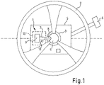
- a steering wheel 2 with a steering wheel column 3 for a motor vehicle can be seen.
- the steering shaft 4 connected to the steering wheel 2 is located in the steering column 3 .
- an electric steering lock locking device 1 is arranged at a suitable point on the steering wheel column 3, the locking device 1 being shown schematically and in a partially broken representation.
- the locking device 1 has a movable between two positions, with the force of a compression spring 28 (see 2 ) acted upon blocking member 7.
- the blocking member 7 can be brought into a latching position 8 on the steering shaft 4 in the steering wheel column 3 corresponding to a first position, so that the blocking member 7 is in locking engagement with the steering shaft 4.
- the steering wheel 2 is then blocked and therefore cannot be turned.
- the locking member 7 is in a second position out of locking or blocking engagement with the latching position 8 on the steering shaft 4, whereby the steering wheel 2 is released for rotation.
- latching position 8 In 1 only one latching position 8 is shown, but several latching positions 8 in the manner of a sprocket can also be provided on the steering shaft 4 in the steering wheel column 3 to block the rotational movement of the steering shaft 4, so that the locking engagement of the locking member 7 can take place in different positions of the steering wheel 2 is enabled.
- the locking device 1 also has a drive 9 for moving the locking member 7 between the two positions.
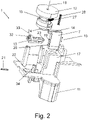
- a housing 10 is also provided for the locking device 1 .
- the housing 10 comprises a base 11 and a cover, in which 2 the lid is omitted.
- the base 11 is made of durable metal, for example die-cast zinc.
- the lid can also be made of metal, but it may also be sufficient if the lid is made of thermoplastic material by means of injection molding.
- the drive 9 comprises an electric motor, not shown in any more detail, and a drive element 12 for moving the blocking member 7 , the blocking member 7 being movably guided in a guide extension 17 in the base 11 .
- the drive element 12 is designed as a worm wheel.
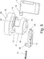
- the worm wheel 12 is configured approximately cylindrically with an upper, first cover surface 29 and a lower, second cover surface 30 and a lateral surface 31 located between the two cover surfaces 29, 30, as shown in more detail in FIG figure 5 can be seen. That Worm wheel 12 has on its circumference, for example on the first cover surface 29, a toothing (not shown) with which a worm on the output shaft of the electric motor meshes, so that the worm wheel 12 can be rotated about an axis of rotation 18 by means of the electric motor.
- the locking member 7 is articulated on the worm wheel 12, namely engages a pin 14 on the locking member 7 in a on the periphery of the worm wheel 12, namely on the lateral surface 31, located cam 15, as further the figure 5 as well as the 6 can be seen.
- the locking member 7 arranged on the worm wheel 12 by rotating the worm wheel 12 by means of the electric motor in the respective direction of rotation in a translatory manner in the direction of the axis of rotation 18 from the first to the second position and from the second to the first position, i.e. between the first and the second position the double arrow 16, movable.
- a securing means 13 for the locking member 7 is provided.
- the securing means 13 is designed both to interact with the locking member 7 in the first position and to interact with the locking member 7 in the second position.
- the securing means 13 acts on the one hand in the manner of a push-back safeguard for the locking member 7 located in the first position to prevent manipulation, with which theft protection is improved.
- the securing means 13 acts in the manner of a securing device for securing the locking member 7 in the second position against unintentional movement into the first position due to a malfunction, which improves the safety of the user from hazards.
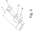
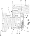
- the securing means 13 For the interaction of the securing means 13 with the locking member 7 are two, in 3 visible recordings 19, 20 in the locking member 7 are provided. In each case one receptacle 19, 20 is provided for latching the securing means 13 in the respective position of the locking member 7, such that the movement of the locking member 7 is blocked in the respective position by means of the securing means 13. As in 8 can be seen in more detail, the securing means 13 engages by means of a locking pin 23 (see also figure 5 ) snap-fit into the first receptacle 19 on the locking member 7 when the locking member 7 is in the first position.
- the securing means 13 acts in the manner of a push-back safety device for the blocking element 7 to increase theft protection.
- the securing means 13 engages by means of the locking pin 23 in a latching manner in the second receptacle 20 on the locking member 7 when the locking member 7 is in the second position. This prevents the locking member 7 from moving out of the second position, with the securing means 13 acting in the manner of a locking device for the locking member 7 to protect against malfunctions.
- the securing means 13 is in a retracted position when the locking member 7 is moved between the first and second positions, so that the movement of the locking member 7 is precluded by the locking pin 23 .
- the securing means 13 is designed in the manner of a slide.
- the securing means 13 is movably arranged in a guide 22 in the base 11 .
- the movement of the securing means 13 is limited by the interaction of a stop 34 in the base 11 with a slot 33 in the securing means 13 .
- the securing means 13 is loaded by means of an elastic element 21, for example by means of a spring, with a force acting in the direction of the receptacle 19, 20.
- the securing means 13 and/or the locking member 7 it is advisable for the securing means 13 and/or the locking member 7 to be made of metal, for example zinc die-cast.
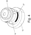
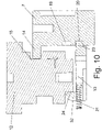
- the securing means 13 can be moved in the guide 22 by means of the connecting link 24 with a corresponding rotation of the drive element 12 against the spring force caused by the elastic element 21, so that the locking pin 23 disengages from the receptacle 19, 20.
- This movement of the securing means 13 is brought about by the eccentrically designed, first section 25 of the connecting link 24, which 7 can be seen closer.
- the securing means 13 is released for movement by means of the connecting link 24 with a corresponding rotation of the drive element 12, so that the locking pin 23, due to the spring force caused by the elastic element 21, moves into the receptacle 19, 20 snaps.
- the signal-generating means consists of a magnet 27 and a Hall sensor, not shown in any more detail, which interacts appropriately with the magnet 27 .
- the magnet 27 is arranged in and/or on the drive element 12, as in figure 5 is shown.
- another sensor can also be used as the signal generating means, for example an electrical switch.
- Such a locking device 1 can be used not only as a steering wheel lock on the steering wheel column but also on another functionally relevant component and/or operating unit of the motor vehicle.
- a component and/or operating assembly can be, for example, the gear shift lever, the selector lever for an automatic transmission, the starter or the like.
- a locking device 1 can also be used in another lock, for example in a door lock for a motor vehicle, for a property or the like.
Landscapes
- Engineering & Computer Science (AREA)
- Mechanical Engineering (AREA)
- General Engineering & Computer Science (AREA)
- Chemical & Material Sciences (AREA)
- Combustion & Propulsion (AREA)
- Transportation (AREA)
- Lock And Its Accessories (AREA)
Applications Claiming Priority (2)
| Application Number | Priority Date | Filing Date | Title |
|---|---|---|---|
| DE102017004505 | 2017-05-11 | ||
| PCT/EP2018/061798 WO2018206546A1 (de) | 2017-05-11 | 2018-05-08 | Verriegelungseinrichtung, insbesondere für ein kraftfahrzeug |
Publications (2)
| Publication Number | Publication Date |
|---|---|
| EP3621855A1 EP3621855A1 (de) | 2020-03-18 |
| EP3621855B1 true EP3621855B1 (de) | 2022-07-06 |
Family
ID=62196530
Family Applications (1)
| Application Number | Title | Priority Date | Filing Date |
|---|---|---|---|
| EP18725435.4A Active EP3621855B1 (de) | 2017-05-11 | 2018-05-08 | Verriegelungseinrichtung, insbesondere für ein kraftfahrzeug |
Country Status (7)
| Country | Link |
|---|---|
| US (1) | US20200122682A1 (enExample) |
| EP (1) | EP3621855B1 (enExample) |
| JP (1) | JP2020519524A (enExample) |
| KR (1) | KR20200006992A (enExample) |
| CN (1) | CN110621553A (enExample) |
| DE (1) | DE102018003614A1 (enExample) |
| WO (1) | WO2018206546A1 (enExample) |
Families Citing this family (4)
| Publication number | Priority date | Publication date | Assignee | Title |
|---|---|---|---|---|
| JP7175175B2 (ja) * | 2018-12-12 | 2022-11-18 | 株式会社ユーシン | 電動ステアリングロック装置 |
| JP7175176B2 (ja) * | 2018-12-12 | 2022-11-18 | 株式会社ユーシン | 電動ステアリングロック装置 |
| DE102019009036A1 (de) * | 2019-12-31 | 2021-07-01 | Marquardt Gmbh | Verriegelungseinrichtung, insbesondere für ein Kraftfahrzeug |
| DE102020128901A1 (de) * | 2020-11-03 | 2022-05-05 | Huf Hülsbeck & Fürst Gmbh & Co. Kg | Vorrichtung zum Sperren und Freigeben eines funktionswesentlichen Bauteils eines Kraftfahrzeuges |
Family Cites Families (20)
| Publication number | Priority date | Publication date | Assignee | Title |
|---|---|---|---|---|
| IT1155605B (it) * | 1982-02-12 | 1987-01-28 | Champion Spark Plug Italiana | Antifurto bloccasterzo per autoveicoli |
| DE4434587B4 (de) | 1993-10-01 | 2004-12-16 | Marquardt Gmbh | Elektronisches Zündstartschloßsystem an einem Kraftfahrzeug |
| AU7628398A (en) * | 1997-09-12 | 1999-03-25 | Robert Bosch Gmbh | An ignition lock system |
| DE10133408A1 (de) * | 2000-07-19 | 2002-05-02 | Marquardt Gmbh | Verriegelungseinrichtung, insbesondere für ein Kraftfahrzeug |
| JP4038132B2 (ja) * | 2003-01-31 | 2008-01-23 | 株式会社東海理化電機製作所 | 電動ステアリングロック装置 |
| JP2004314745A (ja) * | 2003-04-15 | 2004-11-11 | Tokai Rika Co Ltd | ステアリングロック装置 |
| DE10356660B4 (de) * | 2003-12-04 | 2005-12-08 | Siemens Ag | Elektrische Lenkungsverriegelung mit einem Kurvengetriebe |
| JP2006044573A (ja) * | 2004-08-06 | 2006-02-16 | Tokai Rika Co Ltd | ステアリングロック装置 |
| JP4763573B2 (ja) * | 2006-10-27 | 2011-08-31 | 株式会社ユーシン | 電動ステアリングロック装置 |
| JP4870520B2 (ja) * | 2006-10-27 | 2012-02-08 | 株式会社ユーシン | 電動ステアリングロック装置 |
| JP5186127B2 (ja) * | 2007-03-29 | 2013-04-17 | 株式会社アルファ | ステアリングロック装置 |
| KR100901626B1 (ko) * | 2007-09-12 | 2009-06-08 | 현대자동차주식회사 | 스티어링 컬럼 록킹장치 |
| JP5252899B2 (ja) * | 2007-10-01 | 2013-07-31 | 株式会社アルファ | 電動ステアリングロック装置 |
| DE102007059710B4 (de) * | 2007-12-10 | 2021-01-21 | Huf Hülsbeck & Fürst Gmbh & Co. Kg | Kompakte Verriegelungsvorrichtung mit Sicherungselement |
| DE102008013487A1 (de) * | 2008-03-10 | 2009-09-17 | Huf Hülsbeck & Fürst Gmbh & Co. Kg | Verfahren sowie Vorrichtung zur Ansteuerung eines Sperrgliedes |
| JP2009279983A (ja) * | 2008-05-20 | 2009-12-03 | Tokai Rika Co Ltd | ステアリングロック装置 |
| CN102036860B (zh) * | 2008-06-06 | 2013-06-12 | 本田技研工业株式会社 | 转向锁定装置 |
| DE102008032586A1 (de) * | 2008-07-11 | 2010-01-14 | Huf Hülsbeck & Fürst Gmbh & Co. Kg | Verfahren zum Betrieb eines Steuerungssystems eines Motorrads |
| JP5636255B2 (ja) * | 2010-10-20 | 2014-12-03 | 株式会社ユーシン | 電動ステアリングロック装置 |
| CN202186352U (zh) * | 2011-08-24 | 2012-04-11 | 马夸特开关(上海)有限公司 | 电子转向柱锁定系统的锁止装置 |
-
2018
- 2018-05-07 DE DE102018003614.7A patent/DE102018003614A1/de not_active Withdrawn
- 2018-05-08 WO PCT/EP2018/061798 patent/WO2018206546A1/de not_active Ceased
- 2018-05-08 JP JP2019562347A patent/JP2020519524A/ja active Pending
- 2018-05-08 KR KR1020197036146A patent/KR20200006992A/ko not_active Withdrawn
- 2018-05-08 CN CN201880031032.4A patent/CN110621553A/zh active Pending
- 2018-05-08 EP EP18725435.4A patent/EP3621855B1/de active Active
-
2019
- 2019-10-31 US US16/669,926 patent/US20200122682A1/en not_active Abandoned
Also Published As
| Publication number | Publication date |
|---|---|
| EP3621855A1 (de) | 2020-03-18 |
| KR20200006992A (ko) | 2020-01-21 |
| WO2018206546A1 (de) | 2018-11-15 |
| CN110621553A (zh) | 2019-12-27 |
| DE102018003614A1 (de) | 2018-11-15 |
| US20200122682A1 (en) | 2020-04-23 |
| JP2020519524A (ja) | 2020-07-02 |
Similar Documents
| Publication | Publication Date | Title |
|---|---|---|
| DE4436091C1 (de) | Lenkvorrichtung für Kraftfahrzeuge | |
| EP1032513B1 (de) | Verriegelungseinrichtung für lenkungen von kraftfahrzeugen | |
| EP3621855B1 (de) | Verriegelungseinrichtung, insbesondere für ein kraftfahrzeug | |
| DE10133408A1 (de) | Verriegelungseinrichtung, insbesondere für ein Kraftfahrzeug | |
| EP2920389B1 (de) | Kraftfahrzeugtür | |
| EP2539188B1 (de) | Lenkschlossvorrichtung für ein kraftfahrzeug | |
| EP1279576B1 (de) | Zündschlosssystem für ein Kraftfahrzeug | |
| EP1135284B1 (de) | Schliessystem, insbesondere für kraftfahrzeuge | |
| EP3784855B1 (de) | Kraftfahrzeugschloss | |
| EP3375957B1 (de) | Zuhaltevorrichtung | |
| EP2642049B1 (de) | Handhabe eines Kraftfahrzeuges mit einem bewegbaren Abdeckelement | |
| DE10353195A1 (de) | Zündschloßsystem für ein Kraftfahrzeug | |
| WO2019206362A1 (de) | Kraftfahrzeugschloss | |
| EP3227147B1 (de) | Verriegelungseinrichtung für ein kraftfahrzeug | |
| DE10107992B4 (de) | Zündschloßsystem für ein Kraftfahrzeug | |
| DE3242152C2 (enExample) | ||
| EP4399377A1 (de) | Kraftfahrzeugschloss | |
| EP1602538B1 (de) | Elektrische Lenkungsverriegelung, insbesondere für ein Kraftfahrzeug | |
| DE102005025834A1 (de) | Elektrische Lenkungsverriegelung, insbesondere für ein Kraftfahrzeug | |
| DE10022831A1 (de) | Verriegelungseinrichtung, insbesondere für ein Kraftfahrzeug | |
| DE10022830A1 (de) | Verriegelungseinrichtung, insbesondere für ein Kraftfahrzeug | |
| EP3521682B9 (de) | Sicherheitsschalter | |
| DE102013004381A1 (de) | Eingabeeinheit für ein druck- und drehbetätigbares Bedienelement | |
| EP3894282A1 (de) | Verriegelungseinrichtung, insbesondere für ein kraftfahrzeug | |
| EP3453579B1 (de) | Verriegelungsvorrichtung |
Legal Events
| Date | Code | Title | Description |
|---|---|---|---|
| STAA | Information on the status of an ep patent application or granted ep patent |
Free format text: STATUS: UNKNOWN |
|
| STAA | Information on the status of an ep patent application or granted ep patent |
Free format text: STATUS: THE INTERNATIONAL PUBLICATION HAS BEEN MADE |
|
| PUAI | Public reference made under article 153(3) epc to a published international application that has entered the european phase |
Free format text: ORIGINAL CODE: 0009012 |
|
| STAA | Information on the status of an ep patent application or granted ep patent |
Free format text: STATUS: REQUEST FOR EXAMINATION WAS MADE |
|
| 17P | Request for examination filed |
Effective date: 20191015 |
|
| AK | Designated contracting states |
Kind code of ref document: A1 Designated state(s): AL AT BE BG CH CY CZ DE DK EE ES FI FR GB GR HR HU IE IS IT LI LT LU LV MC MK MT NL NO PL PT RO RS SE SI SK SM TR |
|
| AX | Request for extension of the european patent |
Extension state: BA ME |
|
| DAV | Request for validation of the european patent (deleted) | ||
| DAX | Request for extension of the european patent (deleted) | ||
| GRAP | Despatch of communication of intention to grant a patent |
Free format text: ORIGINAL CODE: EPIDOSNIGR1 |
|
| STAA | Information on the status of an ep patent application or granted ep patent |
Free format text: STATUS: GRANT OF PATENT IS INTENDED |
|
| INTG | Intention to grant announced |
Effective date: 20220324 |
|
| GRAS | Grant fee paid |
Free format text: ORIGINAL CODE: EPIDOSNIGR3 |
|
| GRAA | (expected) grant |
Free format text: ORIGINAL CODE: 0009210 |
|
| STAA | Information on the status of an ep patent application or granted ep patent |
Free format text: STATUS: THE PATENT HAS BEEN GRANTED |
|
| AK | Designated contracting states |
Kind code of ref document: B1 Designated state(s): AL AT BE BG CH CY CZ DE DK EE ES FI FR GB GR HR HU IE IS IT LI LT LU LV MC MK MT NL NO PL PT RO RS SE SI SK SM TR |
|
| REG | Reference to a national code |
Ref country code: AT Ref legal event code: REF Ref document number: 1502658 Country of ref document: AT Kind code of ref document: T Effective date: 20220715 Ref country code: CH Ref legal event code: EP |
|
| REG | Reference to a national code |
Ref country code: DE Ref legal event code: R096 Ref document number: 502018010092 Country of ref document: DE |
|
| REG | Reference to a national code |
Ref country code: IE Ref legal event code: FG4D Free format text: LANGUAGE OF EP DOCUMENT: GERMAN |
|
| REG | Reference to a national code |
Ref country code: LT Ref legal event code: MG9D |
|
| REG | Reference to a national code |
Ref country code: NL Ref legal event code: MP Effective date: 20220706 |
|
| PG25 | Lapsed in a contracting state [announced via postgrant information from national office to epo] |
Ref country code: SE Free format text: LAPSE BECAUSE OF FAILURE TO SUBMIT A TRANSLATION OF THE DESCRIPTION OR TO PAY THE FEE WITHIN THE PRESCRIBED TIME-LIMIT Effective date: 20220706 Ref country code: RS Free format text: LAPSE BECAUSE OF FAILURE TO SUBMIT A TRANSLATION OF THE DESCRIPTION OR TO PAY THE FEE WITHIN THE PRESCRIBED TIME-LIMIT Effective date: 20220706 Ref country code: PT Free format text: LAPSE BECAUSE OF FAILURE TO SUBMIT A TRANSLATION OF THE DESCRIPTION OR TO PAY THE FEE WITHIN THE PRESCRIBED TIME-LIMIT Effective date: 20221107 Ref country code: NO Free format text: LAPSE BECAUSE OF FAILURE TO SUBMIT A TRANSLATION OF THE DESCRIPTION OR TO PAY THE FEE WITHIN THE PRESCRIBED TIME-LIMIT Effective date: 20221006 Ref country code: NL Free format text: LAPSE BECAUSE OF FAILURE TO SUBMIT A TRANSLATION OF THE DESCRIPTION OR TO PAY THE FEE WITHIN THE PRESCRIBED TIME-LIMIT Effective date: 20220706 Ref country code: LV Free format text: LAPSE BECAUSE OF FAILURE TO SUBMIT A TRANSLATION OF THE DESCRIPTION OR TO PAY THE FEE WITHIN THE PRESCRIBED TIME-LIMIT Effective date: 20220706 Ref country code: LT Free format text: LAPSE BECAUSE OF FAILURE TO SUBMIT A TRANSLATION OF THE DESCRIPTION OR TO PAY THE FEE WITHIN THE PRESCRIBED TIME-LIMIT Effective date: 20220706 Ref country code: FI Free format text: LAPSE BECAUSE OF FAILURE TO SUBMIT A TRANSLATION OF THE DESCRIPTION OR TO PAY THE FEE WITHIN THE PRESCRIBED TIME-LIMIT Effective date: 20220706 Ref country code: ES Free format text: LAPSE BECAUSE OF FAILURE TO SUBMIT A TRANSLATION OF THE DESCRIPTION OR TO PAY THE FEE WITHIN THE PRESCRIBED TIME-LIMIT Effective date: 20220706 |
|
| PG25 | Lapsed in a contracting state [announced via postgrant information from national office to epo] |
Ref country code: PL Free format text: LAPSE BECAUSE OF FAILURE TO SUBMIT A TRANSLATION OF THE DESCRIPTION OR TO PAY THE FEE WITHIN THE PRESCRIBED TIME-LIMIT Effective date: 20220706 Ref country code: IS Free format text: LAPSE BECAUSE OF FAILURE TO SUBMIT A TRANSLATION OF THE DESCRIPTION OR TO PAY THE FEE WITHIN THE PRESCRIBED TIME-LIMIT Effective date: 20221106 Ref country code: HR Free format text: LAPSE BECAUSE OF FAILURE TO SUBMIT A TRANSLATION OF THE DESCRIPTION OR TO PAY THE FEE WITHIN THE PRESCRIBED TIME-LIMIT Effective date: 20220706 Ref country code: GR Free format text: LAPSE BECAUSE OF FAILURE TO SUBMIT A TRANSLATION OF THE DESCRIPTION OR TO PAY THE FEE WITHIN THE PRESCRIBED TIME-LIMIT Effective date: 20221007 |
|
| REG | Reference to a national code |
Ref country code: DE Ref legal event code: R097 Ref document number: 502018010092 Country of ref document: DE |
|
| PG25 | Lapsed in a contracting state [announced via postgrant information from national office to epo] |
Ref country code: SM Free format text: LAPSE BECAUSE OF FAILURE TO SUBMIT A TRANSLATION OF THE DESCRIPTION OR TO PAY THE FEE WITHIN THE PRESCRIBED TIME-LIMIT Effective date: 20220706 Ref country code: RO Free format text: LAPSE BECAUSE OF FAILURE TO SUBMIT A TRANSLATION OF THE DESCRIPTION OR TO PAY THE FEE WITHIN THE PRESCRIBED TIME-LIMIT Effective date: 20220706 Ref country code: DK Free format text: LAPSE BECAUSE OF FAILURE TO SUBMIT A TRANSLATION OF THE DESCRIPTION OR TO PAY THE FEE WITHIN THE PRESCRIBED TIME-LIMIT Effective date: 20220706 Ref country code: CZ Free format text: LAPSE BECAUSE OF FAILURE TO SUBMIT A TRANSLATION OF THE DESCRIPTION OR TO PAY THE FEE WITHIN THE PRESCRIBED TIME-LIMIT Effective date: 20220706 |
|
| PLBE | No opposition filed within time limit |
Free format text: ORIGINAL CODE: 0009261 |
|
| STAA | Information on the status of an ep patent application or granted ep patent |
Free format text: STATUS: NO OPPOSITION FILED WITHIN TIME LIMIT |
|
| PG25 | Lapsed in a contracting state [announced via postgrant information from national office to epo] |
Ref country code: SK Free format text: LAPSE BECAUSE OF FAILURE TO SUBMIT A TRANSLATION OF THE DESCRIPTION OR TO PAY THE FEE WITHIN THE PRESCRIBED TIME-LIMIT Effective date: 20220706 Ref country code: EE Free format text: LAPSE BECAUSE OF FAILURE TO SUBMIT A TRANSLATION OF THE DESCRIPTION OR TO PAY THE FEE WITHIN THE PRESCRIBED TIME-LIMIT Effective date: 20220706 |
|
| 26N | No opposition filed |
Effective date: 20230411 |
|
| PG25 | Lapsed in a contracting state [announced via postgrant information from national office to epo] |
Ref country code: AL Free format text: LAPSE BECAUSE OF FAILURE TO SUBMIT A TRANSLATION OF THE DESCRIPTION OR TO PAY THE FEE WITHIN THE PRESCRIBED TIME-LIMIT Effective date: 20220706 |
|
| PG25 | Lapsed in a contracting state [announced via postgrant information from national office to epo] |
Ref country code: SI Free format text: LAPSE BECAUSE OF FAILURE TO SUBMIT A TRANSLATION OF THE DESCRIPTION OR TO PAY THE FEE WITHIN THE PRESCRIBED TIME-LIMIT Effective date: 20220706 |
|
| REG | Reference to a national code |
Ref country code: DE Ref legal event code: R119 Ref document number: 502018010092 Country of ref document: DE |
|
| REG | Reference to a national code |
Ref country code: CH Ref legal event code: PL |
|
| PG25 | Lapsed in a contracting state [announced via postgrant information from national office to epo] |
Ref country code: MC Free format text: LAPSE BECAUSE OF FAILURE TO SUBMIT A TRANSLATION OF THE DESCRIPTION OR TO PAY THE FEE WITHIN THE PRESCRIBED TIME-LIMIT Effective date: 20220706 |
|
| GBPC | Gb: european patent ceased through non-payment of renewal fee |
Effective date: 20230508 |
|
| REG | Reference to a national code |
Ref country code: BE Ref legal event code: MM Effective date: 20230531 |
|
| PG25 | Lapsed in a contracting state [announced via postgrant information from national office to epo] |
Ref country code: MC Free format text: LAPSE BECAUSE OF FAILURE TO SUBMIT A TRANSLATION OF THE DESCRIPTION OR TO PAY THE FEE WITHIN THE PRESCRIBED TIME-LIMIT Effective date: 20220706 Ref country code: LU Free format text: LAPSE BECAUSE OF NON-PAYMENT OF DUE FEES Effective date: 20230508 Ref country code: LI Free format text: LAPSE BECAUSE OF NON-PAYMENT OF DUE FEES Effective date: 20230531 Ref country code: IT Free format text: LAPSE BECAUSE OF FAILURE TO SUBMIT A TRANSLATION OF THE DESCRIPTION OR TO PAY THE FEE WITHIN THE PRESCRIBED TIME-LIMIT Effective date: 20220706 Ref country code: CH Free format text: LAPSE BECAUSE OF NON-PAYMENT OF DUE FEES Effective date: 20230531 |
|
| REG | Reference to a national code |
Ref country code: IE Ref legal event code: MM4A |
|
| PG25 | Lapsed in a contracting state [announced via postgrant information from national office to epo] |
Ref country code: IE Free format text: LAPSE BECAUSE OF NON-PAYMENT OF DUE FEES Effective date: 20230508 |
|
| PG25 | Lapsed in a contracting state [announced via postgrant information from national office to epo] |
Ref country code: IE Free format text: LAPSE BECAUSE OF NON-PAYMENT OF DUE FEES Effective date: 20230508 Ref country code: DE Free format text: LAPSE BECAUSE OF NON-PAYMENT OF DUE FEES Effective date: 20231201 Ref country code: GB Free format text: LAPSE BECAUSE OF NON-PAYMENT OF DUE FEES Effective date: 20230508 |
|
| PG25 | Lapsed in a contracting state [announced via postgrant information from national office to epo] |
Ref country code: FR Free format text: LAPSE BECAUSE OF NON-PAYMENT OF DUE FEES Effective date: 20230531 Ref country code: BE Free format text: LAPSE BECAUSE OF NON-PAYMENT OF DUE FEES Effective date: 20230531 |
|
| REG | Reference to a national code |
Ref country code: AT Ref legal event code: MM01 Ref document number: 1502658 Country of ref document: AT Kind code of ref document: T Effective date: 20230508 |
|
| PG25 | Lapsed in a contracting state [announced via postgrant information from national office to epo] |
Ref country code: AT Free format text: LAPSE BECAUSE OF NON-PAYMENT OF DUE FEES Effective date: 20230508 |
|
| PG25 | Lapsed in a contracting state [announced via postgrant information from national office to epo] |
Ref country code: AT Free format text: LAPSE BECAUSE OF NON-PAYMENT OF DUE FEES Effective date: 20230508 |
|
| PG25 | Lapsed in a contracting state [announced via postgrant information from national office to epo] |
Ref country code: BG Free format text: LAPSE BECAUSE OF FAILURE TO SUBMIT A TRANSLATION OF THE DESCRIPTION OR TO PAY THE FEE WITHIN THE PRESCRIBED TIME-LIMIT Effective date: 20220706 |
|
| PG25 | Lapsed in a contracting state [announced via postgrant information from national office to epo] |
Ref country code: BG Free format text: LAPSE BECAUSE OF FAILURE TO SUBMIT A TRANSLATION OF THE DESCRIPTION OR TO PAY THE FEE WITHIN THE PRESCRIBED TIME-LIMIT Effective date: 20220706 |
|
| PG25 | Lapsed in a contracting state [announced via postgrant information from national office to epo] |
Ref country code: CY Free format text: LAPSE BECAUSE OF FAILURE TO SUBMIT A TRANSLATION OF THE DESCRIPTION OR TO PAY THE FEE WITHIN THE PRESCRIBED TIME-LIMIT; INVALID AB INITIO Effective date: 20180508 |
|
| PG25 | Lapsed in a contracting state [announced via postgrant information from national office to epo] |
Ref country code: HU Free format text: LAPSE BECAUSE OF FAILURE TO SUBMIT A TRANSLATION OF THE DESCRIPTION OR TO PAY THE FEE WITHIN THE PRESCRIBED TIME-LIMIT; INVALID AB INITIO Effective date: 20180508 |
|
| PG25 | Lapsed in a contracting state [announced via postgrant information from national office to epo] |
Ref country code: TR Free format text: LAPSE BECAUSE OF FAILURE TO SUBMIT A TRANSLATION OF THE DESCRIPTION OR TO PAY THE FEE WITHIN THE PRESCRIBED TIME-LIMIT Effective date: 20220706 |