EP3620746A1 - Traverse-type measurement method for dual-system bilateral-survey composite level - Google Patents
Traverse-type measurement method for dual-system bilateral-survey composite level Download PDFInfo
- Publication number
- EP3620746A1 EP3620746A1 EP18794258.6A EP18794258A EP3620746A1 EP 3620746 A1 EP3620746 A1 EP 3620746A1 EP 18794258 A EP18794258 A EP 18794258A EP 3620746 A1 EP3620746 A1 EP 3620746A1
- Authority
- EP
- European Patent Office
- Prior art keywords
- measurement
- survey station
- survey
- level
- observations
- Prior art date
- Legal status (The legal status is an assumption and is not a legal conclusion. Google has not performed a legal analysis and makes no representation as to the accuracy of the status listed.)
- Granted
Links
Images


Classifications
-
- G—PHYSICS
- G01—MEASURING; TESTING
- G01C—MEASURING DISTANCES, LEVELS OR BEARINGS; SURVEYING; NAVIGATION; GYROSCOPIC INSTRUMENTS; PHOTOGRAMMETRY OR VIDEOGRAMMETRY
- G01C5/00—Measuring height; Measuring distances transverse to line of sight; Levelling between separated points; Surveyors' levels
-
- G—PHYSICS
- G01—MEASURING; TESTING
- G01B—MEASURING LENGTH, THICKNESS OR SIMILAR LINEAR DIMENSIONS; MEASURING ANGLES; MEASURING AREAS; MEASURING IRREGULARITIES OF SURFACES OR CONTOURS
- G01B11/00—Measuring arrangements characterised by the use of optical techniques
-
- G—PHYSICS
- G01—MEASURING; TESTING
- G01B—MEASURING LENGTH, THICKNESS OR SIMILAR LINEAR DIMENSIONS; MEASURING ANGLES; MEASURING AREAS; MEASURING IRREGULARITIES OF SURFACES OR CONTOURS
- G01B21/00—Measuring arrangements or details thereof, where the measuring technique is not covered by the other groups of this subclass, unspecified or not relevant
- G01B21/02—Measuring arrangements or details thereof, where the measuring technique is not covered by the other groups of this subclass, unspecified or not relevant for measuring length, width, or thickness
-
- G—PHYSICS
- G01—MEASURING; TESTING
- G01C—MEASURING DISTANCES, LEVELS OR BEARINGS; SURVEYING; NAVIGATION; GYROSCOPIC INSTRUMENTS; PHOTOGRAMMETRY OR VIDEOGRAMMETRY
- G01C15/00—Surveying instruments or accessories not provided for in groups G01C1/00 - G01C13/00
- G01C15/002—Active optical surveying means
-
- G—PHYSICS
- G01—MEASURING; TESTING
- G01C—MEASURING DISTANCES, LEVELS OR BEARINGS; SURVEYING; NAVIGATION; GYROSCOPIC INSTRUMENTS; PHOTOGRAMMETRY OR VIDEOGRAMMETRY
- G01C15/00—Surveying instruments or accessories not provided for in groups G01C1/00 - G01C13/00
- G01C15/002—Active optical surveying means
- G01C15/004—Reference lines, planes or sectors
-
- G—PHYSICS
- G01—MEASURING; TESTING
- G01C—MEASURING DISTANCES, LEVELS OR BEARINGS; SURVEYING; NAVIGATION; GYROSCOPIC INSTRUMENTS; PHOTOGRAMMETRY OR VIDEOGRAMMETRY
- G01C15/00—Surveying instruments or accessories not provided for in groups G01C1/00 - G01C13/00
- G01C15/02—Means for marking measuring points
- G01C15/06—Surveyors' staffs; Movable markers
-
- G—PHYSICS
- G01—MEASURING; TESTING
- G01C—MEASURING DISTANCES, LEVELS OR BEARINGS; SURVEYING; NAVIGATION; GYROSCOPIC INSTRUMENTS; PHOTOGRAMMETRY OR VIDEOGRAMMETRY
- G01C9/00—Measuring inclination, e.g. by clinometers, by levels
-
- G—PHYSICS
- G01—MEASURING; TESTING
- G01S—RADIO DIRECTION-FINDING; RADIO NAVIGATION; DETERMINING DISTANCE OR VELOCITY BY USE OF RADIO WAVES; LOCATING OR PRESENCE-DETECTING BY USE OF THE REFLECTION OR RERADIATION OF RADIO WAVES; ANALOGOUS ARRANGEMENTS USING OTHER WAVES
- G01S19/00—Satellite radio beacon positioning systems; Determining position, velocity or attitude using signals transmitted by such systems
- G01S19/01—Satellite radio beacon positioning systems transmitting time-stamped messages, e.g. GPS [Global Positioning System], GLONASS [Global Orbiting Navigation Satellite System] or GALILEO
- G01S19/03—Cooperating elements; Interaction or communication between different cooperating elements or between cooperating elements and receivers
- G01S19/07—Cooperating elements; Interaction or communication between different cooperating elements or between cooperating elements and receivers providing data for correcting measured positioning data, e.g. DGPS [differential GPS] or ionosphere corrections
-
- G—PHYSICS
- G01—MEASURING; TESTING
- G01S—RADIO DIRECTION-FINDING; RADIO NAVIGATION; DETERMINING DISTANCE OR VELOCITY BY USE OF RADIO WAVES; LOCATING OR PRESENCE-DETECTING BY USE OF THE REFLECTION OR RERADIATION OF RADIO WAVES; ANALOGOUS ARRANGEMENTS USING OTHER WAVES
- G01S5/00—Position-fixing by co-ordinating two or more direction or position line determinations; Position-fixing by co-ordinating two or more distance determinations
- G01S5/02—Position-fixing by co-ordinating two or more direction or position line determinations; Position-fixing by co-ordinating two or more distance determinations using radio waves
- G01S5/0205—Details
- G01S5/021—Calibration, monitoring or correction
Definitions
- the present invention relates to the field of measurement technologies; in particular, to a traverse-type measurement method for a dual-system bilateral-survey composite level which is specialized to ensure measurement precision, avoid invalid measurements and improve working efficiency.
- a traditional leveling device consists of one level and two leveling staffs. During measurement, the two leveling staffs are separately placed at points A and B on the ground first, and then the level is placed at the middle point between the points A and B. Elevation values of the two leveling staffs are read along the horizontal line of sight of a level telescope after leveling. A difference between the measured elevation values is a level height difference between the points A and B on the ground. If the elevation of one point is known, the elevation of the other point can be figured out according to the height difference.
- the traditional leveling device mainly has the following defects: (1) The measurement has low working efficiency and reliability.
- a ruler-instrument integrated composite level for dual-type observation (hereinafter referred to as a composite level), which has the following structure: a leveling staff and an observation unit (that is, the traditional level) that are parallel to the axis of a cylindrical ruler body are fixed on the same cylindrical surface of the cylindrical ruler body.
- the collimation axis of the observation unit is perpendicular to the axis of the cylindrical ruler body.
- the measurement method thereof includes the following steps: placing instruments, synchronous leveling, mutual alignment, bilateral survey, bidirectional inspection, and so on.
- Point-to-point direct leveling can be implemented effectively, and it is unnecessary to spend much time and energy to figure out a rational location and distance configuration of the level and leveling staff, thereby improving the working efficiency and reliability of leveling.
- Site selection and stationing of leveling are not restricted by terrain environments, so that leveling can be implemented in complex terrain environments such as steep slopes, hollows, ponds, canals and ditches, gullies, rivers, and mountainous areas conveniently.
- Chinese Patent Application No. 201310049994.1 discloses a leveling method suitable for a compound level, and specifically discloses a method for determining angle i (one of instrument parameters) of a composite level and a method for thoroughly eliminating impact of the angle i.
- Chinese Patent Application No. 201410585033.7 discloses a composite level own-side height determination method, and specifically discloses a method for precisely determining the height (one of instrument parameters) of an observation unit (that is, a level) and a method for combined determination of the height and angle i, thereby precisely determining the instrument parameters.
- the height difference measurement methods in the aforementioned patents still adopt a traverse-type measurement mode of the traditional leveling in which measurement proceeds through passing-on of two points.
- the traverse-type measurement mode in which measurement proceeds through passing-on of two composite levels includes the following steps: measuring instrument parameter information, that is, measuring performance parameters of the composite level such as the height and angle i; determining start and end measurement points of a measurement section; and placing instruments and establishing survey stations. A lot of measurement points will be disposed between the start measurement point and the end measurement point of the measurement section, and these measurement points are referred to as transitional measurement points (also known as benchmarks). Starting from the first survey station, two composite levels are separately disposed at a rear measurement point and a front measurement point of the survey station. As shown in FIG. 1 and FIG.
- a measurement point P k is referred to as a rear measurement point and a measurement point P k + 1 is referred to as a front measurement point.
- the distance between the rear measurement point and the front measurement point is a survey station distance D k .
- the survey station distance when the survey station is initially established is referred to as an initial survey station distance, which is denoted by D k 0 .
- the initial survey station distance D k 0 is determined based on the following principle: the initial survey station distance should not be greater than distance tolerance stipulated in national regulations (for fourth-grade measurement, the survey station distance tolerance is 150 m); and it should be ensured that a composite level A and a composite level B are located within height difference observation ranges of instruments (the height difference observation range of current composite levels is 1.5 m). After synchronous observation, an average of measured effective height differences of the two composite levels is calculated as a height difference h k of the current station.
- the composite level at the rear measurement point of the current survey station k is moved to the front measurement point of the next survey station (the front measurement point of the previous station becomes the rear measurement point of the next survey station) to continue to measure a height difference of the survey station k+1, and so on, until the measurement proceeds to the last survey station n and the last measurement point P n + 1 (that is, the end measurement point).
- the sum of all survey station height differences is calculated as a measurement section height difference of this forward measurement (which is referred to as a forward measurement height difference).
- height difference measurement is performed by using the same method in a reverse direction starting from the last measurement point P n + 1 (that is, the original end measurement point), until the measurement proceeds to the original start measurement point.
- the sum of all survey station height differences is calculated as a measurement section height difference of this reverse measurement (which is referred to as a reverse measurement height difference).
- a reverse measurement height difference the traverse-type measurement mode in which measurement proceeds through passing-on of two points requires a roundtrip along a traverse for leveling, so that forward and reverse measurements are carried out to implement closed-loop height difference inspection.
- Chinese Patent Application No. 201410044122.0 discloses a three-point closed layout measurement method for composite levels, and specifically discloses a three-point closed layout measurement method for composite levels that can realize closed inspection in a regional space at any time, ensure measurement precision, and improve overall leveling reliability and efficiency.
- This method extends the traditional two-point traverse-type leveling to three-point closed planar leveling, that is, leveling points are arranged in such a manner that connecting lines of every three adjacent leveling points form a triangle and every two adjacent triangles have one or two common leveling points.
- the three-point closed layout measurement method still has the following problems: (1) instruments and personnel need to be added, and the amount of work is enormous, that is, the method requires high manpower and resource costs; (2) the method has strict requirements on terrain conditions. In other words, unless there is a special need or higher precision and reliability are required in some regions, the three-point closed layout measurement method is not a preferred measurement method for composite levels considering the economic effectiveness, engineering requirement, and practicability for users.
- the present invention provides a traverse-type measurement method for a dual-system bilateral-survey composite level which is specialized to ensure the measurement precision, avoid invalid measurements, and improve working efficiency
- a traverse-type measurement method for a dual-system bilateral-survey composite level including the following steps:
- the present invention is an intelligent traverse-type measurement method for integrated three-level error control loop inspection with the dual-system bilateral survey compound level. Specifically, survey station single-instrument inspection, survey station dual-instrument cross-inspection, and multi-survey station dual-instrument cumulative cross-inspection are adopted, and the number of observations and distance between survey stations are adjusted, such that measurement error is dynamically controlled in real time, ensuring that height difference measurement of survey stations and of measurement sections meets a preset precision requirement regardless of location or time, avoiding the invalid measurements that frequently occur with traditional levels, and improving working efficiency and economic benefit of the composite level.
- the traverse-type measurement method for a dual-system bilateral-survey composite level includes the following steps:
- R A and R B of the observed readings exceed a limit, that is, whether
- R 0 6 mm.
- R 0 can be derived according to national leveling grade requirements or obtained based on numerous practice statistics. It is also feasible to determine whether the standard deviations exceed a limit, that is, whether
- ⁇ ⁇ 0 . In this embodiment, ⁇ 0 1.5 mm. ⁇ 0 can be directly given according to the national leveling grade requirements or obtained based on numerous practice statistics.
- Step 7 is performed.
- the number of observations is increased (the number can be increased by 1 each time or increased based on a particular step size), and it is determined whether the number of observations exceeds a threshold M (M is set to 30 in this embodiment); if the number of observations does not exceed M, Step 5 is performed again, and if the number of observations exceeds M, a front measurement point is moved to reduce a survey station distance, and then it is determined whether the survey station distance D k is less than a threshold D 0 .
- the threshold D 0 can be directly given based on a particular ratio according to distance requirements of the national leveling grades or obtained based on numerous practice statistics.
- D o 1 3 D k o
- Step 1 to Step 6 above form a first-level error control loop.
- Step 8 Determine whether
- Step 6 If
- Step 7 to Step 9 above form a second-level error control loop.
- Step 10 Calculate a cumulative survey station height difference H k A of the composite level A; and calculate a cumulative survey station height difference H k B of the composite level B; that is, separately calculate cumulative height differences of the composite level A and the composite level B from the first survey station to the current survey station k:
- Step 11 Calculate a difference ⁇ AB between the cumulative survey station height differences of the two levels.
- Step 12 Determine whether
- the tolerance ⁇ 0 can be directly given according to the national leveling grade requirements or obtained based on numerous practice statistics.
- Step 13 is performed.
- Step 13 Calculate a sum H k of all survey station height differences.
- Step 14 Determine whether the composite level A is placed at the end measurement point; if no, that is, if the composite level A has not arrived at the end measurement point yet, move a composite level on a rear measurement point of the current survey station k, and perform Step 3 again (place the moved composite level to a front measurement point of the next survey station to establish a new survey station); if yes, end the measurement.
- the composite level A (or the composite level B) is moved from the first measurement point (that is, the start measurement point) to the last measurement point (that is, the end measurement point) to ensure that the total number n+1 of measurement points (including the start measurement point and the end measurement point) is an odd number, and the total number n of survey stations is an even number, thereby further ensuring the precision of height difference measurement.
- Step 10 to Step 13 above form a third-level error control loop.
Landscapes
- Engineering & Computer Science (AREA)
- Physics & Mathematics (AREA)
- General Physics & Mathematics (AREA)
- Radar, Positioning & Navigation (AREA)
- Remote Sensing (AREA)
- Computer Networks & Wireless Communication (AREA)
- Length Measuring Devices With Unspecified Measuring Means (AREA)
- Position Fixing By Use Of Radio Waves (AREA)
- Length Measuring Devices By Optical Means (AREA)
- Testing Or Calibration Of Command Recording Devices (AREA)
Abstract
Description
- The present invention relates to the field of measurement technologies; in particular, to a traverse-type measurement method for a dual-system bilateral-survey composite level which is specialized to ensure measurement precision, avoid invalid measurements and improve working efficiency.
- A traditional leveling device consists of one level and two leveling staffs. During measurement, the two leveling staffs are separately placed at points A and B on the ground first, and then the level is placed at the middle point between the points A and B. Elevation values of the two leveling staffs are read along the horizontal line of sight of a level telescope after leveling. A difference between the measured elevation values is a level height difference between the points A and B on the ground. If the elevation of one point is known, the elevation of the other point can be figured out according to the height difference. The traditional leveling device mainly has the following defects: (1) The measurement has low working efficiency and reliability. It usually takes a lot of energy and time of measurement personnel to achieve a rational location configuration of three points, i.e., the level and the two leveling staffs, in a complex terrain environment, affecting the measurement efficiency. (2) Measurements are restricted by terrain environments. In complex terrain environments such as steep slopes, hollows, ponds, canals and ditches, gullies, rivers, and mountainous areas, it is generally impossible to set up the level at the middle point between the two leveling staffs, thus failing to implement leveling. In order to overcome the aforementioned defects, Chinese Patent Application No.
201220611636.6 - Chinese Patent Application No.
201310049994.1 201410585033.7 FIG. 1 andFIG. 2 , for a survey station k, a measurement point Pk is referred to as a rear measurement point and a measurement point P k+1 is referred to as a front measurement point. The distance between the rear measurement point and the front measurement point is a survey station distance Dk. The survey station distance when the survey station is initially established is referred to as an initial survey station distance, which is denoted by

- In order to solve the foregoing problems in the traverse-type measurement mode in which measurement proceeds through passing-on of two points, Chinese Patent Application No.
201410044122.0 - In order to solve the aforementioned technical problems of the prior art, the present invention provides a traverse-type measurement method for a dual-system bilateral-survey composite level which is specialized to ensure the measurement precision, avoid invalid measurements, and improve working efficiency
- The present invention adopts the following technical solution: a traverse-type measurement method for a dual-system bilateral-survey composite level, including the following steps:
- Step 1: measuring instrument parameter information;
- Step 2: determining start and end measurement points of a measurement section, and placing a composite level A at the start measurement point;
- Step 3: placing instruments and establishing survey stations;
- Step 4: setting an initial number of observations;
- Step 5: separately observing readings on the composite level A and a composite level B according to the set number of observations, and separately calculating errors of the readings;
- Step 6: determining whether the errors of the readings exceed a limit,
where if the errors do not exceed the limit, Step 7 is performed; if any error exceeds the limit, the number of observations is increased and it is determined whether the number of observations exceeds a threshold M; if the number of observations does not exceed M, Step 5 is performed again, and if the number of observations exceeds M, a front measurement point is moved to reduce a survey station distance, and then it is determined whether the survey station distance Dk is less than a threshold D0 ; if Dk is less than D0 , the measurement is ended; otherwise, Step 3 is performed again; - Step 7: calculating an average reading of the composite level A as a survey station height difference


- Step 8: determining whether |δ AB| exceeds tolerance δ 0,
where if |δ AB| does not exceed δ 0, Step 9 is performed; and
if |δ AB| exceeds δ 0, the number of observations is increased and then it is determined whether the number of observations exceeds the threshold M; if the number of observations does not exceed M, Step 5 is performed again, and if the number of observations exceeds M, the front measurement point is moved to reduce the survey station distance, and then it is determined whether the survey station distance Dk is less than the threshold D0 ; if Dk is less than D0, the measurement is ended; otherwise, Step 3 is performed again; - Step 9: calculating an average of the survey station height differences of the two levels as a height difference hk of the current survey station;
- Step 10: calculating a cumulative survey station height difference


- Step 11: calculating a difference ΔAB between the cumulative survey station height differences of the two levels;
- Step 12: determining whether |ΔAB| exceeds tolerance Δ0,
where if |ΔAB| exceeds Δ0, the front measurement point is moved to reduce the survey station distance, and then it is determined whether the survey station distance Dk is less than the threshold D0 ; if Dk is less than D0 , the measurement is ended; otherwise, Step 3 is performed again; and
if |ΔAB| does not exceed Δ0, Step 13 is performed; - Step 13: calculating a sum Hk of all survey station height differences; and
- Step 14: determining whether the composite level A is placed at the end measurement point; if not, moving a composite level on a rear measurement point, and performing Step 3 again; if yes, ending the measurement.
- The present invention is an intelligent traverse-type measurement method for integrated three-level error control loop inspection with the dual-system bilateral survey compound level. Specifically, survey station single-instrument inspection, survey station dual-instrument cross-inspection, and multi-survey station dual-instrument cumulative cross-inspection are adopted, and the number of observations and distance between survey stations are adjusted, such that measurement error is dynamically controlled in real time, ensuring that height difference measurement of survey stations and of measurement sections meets a preset precision requirement regardless of location or time, avoiding the invalid measurements that frequently occur with traditional levels, and improving working efficiency and economic benefit of the composite level.
-
-
FIG. 1 is a schematic diagram of arrangement of measurement sections and survey stations according to an embodiment of the present invention. -
FIG. 2 is a schematic diagram of measurement point placement of composite levels A and B according to an embodiment of the present invention. -
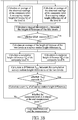
FIG. 3 (FIG. 3A andFIG. 3B ) is a flowchart of an embodiment of the present invention. - As shown in
FIG. 1 ,FIG. 2 andFIG. 3 (FIG. 3A andFIG. 3B ), the traverse-type measurement method for a dual-system bilateral-survey composite level according to the present invention includes the following steps: - Step 1: Measure instrument parameter information. That is, performance parameters of a composite level A and a composite level B, such as the height and angle i of the composite levels, are measured according to the existing technology. The performance parameters should meet design requirements of the composite levels.
- Step 2: Determine start and end measurement points of a measurement section, and place the composite level A at the start measurement point, as shown in
FIG. 1 . - Step 3: Place instruments and establish survey stations. That is, the composite level A and the composite level B are placed at adjacent measurement points for synchronous observation, i.e., the two composite levels form a survey station. For establishment of the first survey station, it is only necessary to place the composite level B at an adjacent measurement point because the composite level A is already placed at the start measurement point in
Step 2. Establishment of the kth survey station is as shown inFIG. 2 . Synchronous leveling and scale cross reference are carried out after the instruments are placed. - Step 4: Set an initial number of observations to 5.
- Step 5: Observe readings on the composite level A according to the set number of observations (an observed reading refers to a value obtained by correcting a collimated reading of a composite level observation unit according to the instrument parameter information such as the angle i and instrument height based on the existing technology), and calculate a range RA (maximum observed reading-minimum observed reading) of the observed readings; observe readings on the composite level B according to the set number of observations, and calculate a range RB of the readings; alternatively, separately calculate standard deviations σ A and σ B of the observed readings, where the standard deviations σ A and σ B of the observed readings can be calculated according to a formula in the existing technology.
- Step 6: Determine whether errors of the readings exceed a limit.
- It is determined whether the ranges RA and RB of the observed readings exceed a limit, that is, whether |RA|≤R0 and |RB|≤R0. In this embodiment, R0=6 mm. R0 can be derived according to national leveling grade requirements or obtained based on numerous practice statistics. It is also feasible to determine whether the standard deviations exceed a limit, that is, whether |σ A|≤σ 0 and |σ B|≤σ 0. In this embodiment, σ 0=1.5 mm. σ 0 can be directly given according to the national leveling grade requirements or obtained based on numerous practice statistics.
- If the errors do not exceed the limit, Step 7 is performed.
- If any error exceeds the limit, the number of observations is increased (the number can be increased by 1 each time or increased based on a particular step size), and it is determined whether the number of observations exceeds a threshold M (M is set to 30 in this embodiment); if the number of observations does not exceed M, Step 5 is performed again, and if the number of observations exceeds M, a front measurement point is moved to reduce a survey station distance, and then it is determined whether the survey station distance Dk is less than a threshold D0. The threshold D0 can be directly given based on a particular ratio according to distance requirements of the national leveling grades or obtained based on numerous practice statistics. In this embodiment,


- It should be noted that
Step 1 to Step 6 above form a first-level error control loop. - Step 7: Calculate an average reading of the composite level A as a survey station height difference


- Step 8: Determine whether |δ AB| exceeds tolerance δ 0. The tolerance δ 0 can be directly given according to the national leveling grade requirements or obtained based on numerous practice statistics. In this embodiment, δ 0=5 mm.
If |δ AB| does not exceed δ 0, Step 9 is performed; - If |δ AB| exceeds δ 0, the number of observations is increased as in Step 6, and then it is determined whether the number of observations exceeds the threshold M; if the number of observations does not exceed M, Step 5 is performed again, and if the number of observations exceeds M, the front measurement point is moved to reduce the survey station distance, and then it is determined whether the survey station distance Dk is less than the threshold D0 ; if Dk is less than D0, the measurement is ended; otherwise, Step 3 is performed again.
- Step 9: Calculate a height difference hk of the current survey station, that is, calculate an average hk of the survey station height differences


- It should be noted that Step 7 to Step 9 above form a second-level error control loop.
- Step 10: Calculate a cumulative survey station height difference


- Step 11: Calculate a difference ΔAB between the cumulative survey station height differences of the two levels.
- Step 12: Determine whether |ΔAB| exceeds tolerance Δ0. The tolerance Δ0 can be directly given according to the national leveling grade requirements or obtained based on numerous practice statistics. In this embodiment,


- If |ΔAB| exceeds Δ0, the front measurement point is moved to reduce the survey station distance, and then it is determined whether the survey station distance Dk is less than the threshold D0 ; if Dk is less than D0, the measurement is ended; otherwise, Step 3 is performed again.
- If |ΔAB| does not exceed Δ0, Step 13 is performed.
- Step 13: Calculate a sum Hk of all survey station height differences.

- Step 14: Determine whether the composite level A is placed at the end measurement point; if no, that is, if the composite level A has not arrived at the end measurement point yet, move a composite level on a rear measurement point of the current survey station k, and perform Step 3 again (place the moved composite level to a front measurement point of the next survey station to establish a new survey station); if yes, end the measurement.
- During establishment of measurement sections and survey stations, the composite level A (or the composite level B) is moved from the first measurement point (that is, the start measurement point) to the last measurement point (that is, the end measurement point) to ensure that the total number n+1 of measurement points (including the start measurement point and the end measurement point) is an odd number, and the total number n of survey stations is an even number, thereby further ensuring the precision of height difference measurement.
- It should be noted that Step 10 to Step 13 above form a third-level error control loop.
- It can be known from the embodiment that only the following two situations can occur during implementation of the present invention: (1) if measurement is permitted, a qualified result will be obtained through measurement; (2) if the measurement condition is too poor to carry out measurement, the current measurement is given up directly, thereby effectively avoiding invalid measurements that occur in the traditional traverse-type measurement mode, and effectively improving working efficiency of leveling.
Claims (1)
- A traverse-type measurement method for a dual-system bilateral-survey composite level, comprising the following steps:Step 1: measuring instrument parameter information;Step 2: determining start and end measurement points of a measurement section, and placing a composite level A at the start measurement point;Step 3: placing instruments and establishing survey stations;Step 4: setting an initial number of observations;Step 5: separately observing readings on the composite level A and a composite level B according to the set number of observations, and separately calculating errors of the readings;Step 6: determining whether the errors of the readings exceed a limit,
wherein if the errors do not exceed the limit, Step 7 is performed; if any error exceeds the limit, the number of observations is increased and it is determined whether the number of observations exceeds a threshold M; if the number of observations does not exceed M, Step 5 is performed again, and if the number of observations exceeds M, a front measurement point is moved to reduce a survey station distance, and then it is determined whether the survey station distance Dk is less than a threshold D0 ; if Dk is less than D0 , the measurement is ended; otherwise, Step 3 is performed again;Step 7: calculating an average reading of the composite level A as a survey station height difference
 Step 8: determining whether |δ AB| exceeds tolerance δ 0,
wherein if |δ AB| does not exceed δ 0, Step 9 is performed; and
if |δ AB| exceeds δ 0, the number of observations is increased and then it is determined whether the number of observations exceeds the threshold M; if the number of observations does not exceed M, Step 5 is performed again, and if the number of observations exceeds M, the front measurement point is moved to reduce the survey station distance, and then it is determined whether the survey station distance Dk is less than the threshold D0 ; if Dk is less than D0 , the measurement is ended; otherwise, Step 3 is performed again;Step 9: calculating an average of the survey station height differences of the two levels as a height difference hk of the current survey station;Step 10: calculating a cumulative survey station height difference
 Step 11: calculating a difference ΔAB between the cumulative survey station height differences of the two levels;Step 12: determining whether |ΔAB| exceeds tolerance Δ0,
wherein if |ΔAB| exceeds Δ0, the front measurement point is moved to reduce the survey station distance, and then it is determined whether the survey station distance Dk is less than the threshold D0 ; if Dk is less than D0 , the measurement is ended; otherwise, Step 3 is performed again; and
if |ΔAB| does not exceed Δ0, Step 13 is performed;Step 13: calculating a sum Hk of all survey station height differences; andStep 14: determining whether the composite level A is placed at the end measurement point; if not, moving a composite level on a rear measurement point, and performing Step 3 again; if yes, ending the measurement.
Applications Claiming Priority (2)
| Application Number | Priority Date | Filing Date | Title |
|---|---|---|---|
| CN201710304982.7A CN107228650B (en) | 2017-05-03 | 2017-05-03 | The Traverse Measurement Method of Dual-system Opposite Observation Composite Level |
| PCT/CN2018/083633 WO2018201907A1 (en) | 2017-05-03 | 2018-04-19 | Traverse-type measurement method for dual-system bilateral-survey composite level |
Publications (3)
| Publication Number | Publication Date |
|---|---|
| EP3620746A1 true EP3620746A1 (en) | 2020-03-11 |
| EP3620746A4 EP3620746A4 (en) | 2020-12-30 |
| EP3620746B1 EP3620746B1 (en) | 2022-01-26 |
Family
ID=59933222
Family Applications (1)
| Application Number | Title | Priority Date | Filing Date |
|---|---|---|---|
| EP18794258.6A Active EP3620746B1 (en) | 2017-05-03 | 2018-04-19 | Traverse-type measurement method for dual-system bilateral-survey composite level |
Country Status (5)
| Country | Link |
|---|---|
| US (1) | US11029151B2 (en) |
| EP (1) | EP3620746B1 (en) |
| JP (1) | JP6695451B2 (en) |
| CN (1) | CN107228650B (en) |
| WO (1) | WO2018201907A1 (en) |
Families Citing this family (8)
| Publication number | Priority date | Publication date | Assignee | Title |
|---|---|---|---|---|
| CN107228650B (en) * | 2017-05-03 | 2018-09-14 | 大连圣博尔测绘仪器科技有限公司 | The Traverse Measurement Method of Dual-system Opposite Observation Composite Level |
| CN108955635B (en) * | 2018-08-09 | 2020-08-14 | 大连圣博尔测绘仪器科技有限公司 | Opposite observation leveling method for double-observation-unit composite level |
| CN110174665B (en) * | 2019-05-31 | 2021-07-13 | 彩虹无人机科技有限公司 | Method for reducing pointing deviation of airborne photoelectric load and hanging point based on laser guidance |
| CN111854796A (en) * | 2020-06-28 | 2020-10-30 | 陕西铁道工程勘察有限公司 | A Real-time Comprehensive Correction Method for Precision Leveling |
| CN114353748A (en) * | 2022-01-06 | 2022-04-15 | 中国十七冶集团有限公司 | Total station triangular elevation back-and-forth measurement method for setting station with distance of 20-40m from prism |
| CN115711606B (en) * | 2022-11-22 | 2024-10-25 | 中国电建集团西北勘测设计研究院有限公司 | Small-diameter TBM tunnel tunneling measurement control transmission method |
| CN115822004B (en) * | 2022-12-13 | 2025-09-12 | 天津市政工程设计研究总院有限公司 | A platform-based monitoring method for highway roadbed settlement and convergence |
| CN118463919A (en) * | 2024-05-15 | 2024-08-09 | 山东黄河顺成水利水电工程有限公司 | A method of precise leveling across the Yellow River |
Family Cites Families (11)
| Publication number | Priority date | Publication date | Assignee | Title |
|---|---|---|---|---|
| GB556379A (en) * | 1942-09-09 | 1943-10-01 | Reginald Victor Edwards | Improvements in or relating to builder's levels |
| JPH0221211A (en) * | 1988-07-08 | 1990-01-24 | Nippon Telegr & Teleph Corp <Ntt> | Automatic level and distance measuring apparatus |
| CN102226697B (en) * | 2011-04-12 | 2012-11-21 | 杨浩 | Precise settlement monitoring method with total station instrument |
| CN102636155A (en) * | 2012-04-28 | 2012-08-15 | 天津二十冶建设有限公司 | Two-instrument simultaneous measuring method for increasing leveling precision |
| CN102778220A (en) * | 2012-07-17 | 2012-11-14 | 刘雁春 | Ruler combinative/composite water level for dual type observation |
| CN103115610B (en) * | 2013-02-08 | 2015-08-12 | 刘雁春 | Be applicable to the leveling measuring method of composite level |
| CN104048644A (en) * | 2013-03-11 | 2014-09-17 | 广东工业大学 | Method for recording and calculating leveling data by mobile phone |
| CN103759705B (en) * | 2014-01-30 | 2017-02-15 | 大连圣博尔测绘仪器科技有限公司 | Three-point Closed Layout Measurement Method for Composite Level |
| CZ305470B6 (en) * | 2014-07-15 | 2015-10-14 | R.O.G. S.R.O. | Method of measuring, processing and using data of terrain digital model for objective evaluation of geometrical parameters of measured objects and measuring apparatus for making the said method |
| CN104316027B (en) * | 2014-10-28 | 2017-02-08 | 大连圣博尔测绘仪器科技有限公司 | Method for Measuring the Altitude of the Composite Level |
| CN107228650B (en) * | 2017-05-03 | 2018-09-14 | 大连圣博尔测绘仪器科技有限公司 | The Traverse Measurement Method of Dual-system Opposite Observation Composite Level |
-
2017
- 2017-05-03 CN CN201710304982.7A patent/CN107228650B/en active Active
-
2018
- 2018-04-19 US US16/312,290 patent/US11029151B2/en active Active
- 2018-04-19 WO PCT/CN2018/083633 patent/WO2018201907A1/en not_active Ceased
- 2018-04-19 JP JP2018568406A patent/JP6695451B2/en active Active
- 2018-04-19 EP EP18794258.6A patent/EP3620746B1/en active Active
Also Published As
| Publication number | Publication date |
|---|---|
| CN107228650B (en) | 2018-09-14 |
| US11029151B2 (en) | 2021-06-08 |
| CN107228650A (en) | 2017-10-03 |
| WO2018201907A1 (en) | 2018-11-08 |
| US20190204077A1 (en) | 2019-07-04 |
| JP2019525154A (en) | 2019-09-05 |
| EP3620746A4 (en) | 2020-12-30 |
| EP3620746B1 (en) | 2022-01-26 |
| JP6695451B2 (en) | 2020-05-20 |
Similar Documents
| Publication | Publication Date | Title |
|---|---|---|
| EP3620746B1 (en) | Traverse-type measurement method for dual-system bilateral-survey composite level | |
| CN104848845B (en) | A virtual double-conductor control measurement method for underground tunnels | |
| CN109358353B (en) | Rapid pit-dividing lofting method for current collection circuit foundation | |
| CN102607516B (en) | Method for measuring standard elevation in nuclear power engineering | |
| CN104674855B (en) | A kind of pit displacement monitoring method based on differential technique | |
| CN105423993A (en) | Deformation monitoring coordinate reference establishment method and device based on three dimensional laser scanning | |
| CN110186426A (en) | A kind of remote triangulated height river-crossing leveling method | |
| CN104631419A (en) | Foundation pit top horizontal displacement monitoring method | |
| CN103115610B (en) | Be applicable to the leveling measuring method of composite level | |
| CN103526783A (en) | Method for measuring horizontal displacement of building foundation ditch | |
| CN105806310A (en) | Method for monitoring earth surface three-dimensional displacement of slope around tunnel entrance by using laser distance measurement instrument | |
| CN114046770A (en) | A method of observation and measurement of marine subsidence | |
| CN102620699A (en) | Method for measuring deformation monitoring directional horizontal displacement by using directional vertical distance method | |
| CN111928828A (en) | Method for quickly calibrating center line and waist line of underground curve | |
| CN103344214B (en) | 1.6-degree parabolic extralarge pier measuring and pier body linear control method | |
| CN108981660A (en) | A kind of Opposite side survey method of triangulated height | |
| CN107386341A (en) | A kind of horizontal displacement measuring system based on collimation line method | |
| CN103759705B (en) | Three-point Closed Layout Measurement Method for Composite Level | |
| CN207228180U (en) | A kind of horizontal displacement measuring system based on collimation line method | |
| CN117166547A (en) | Foundation pit construction measurement methods | |
| CN118548863A (en) | Method and system for optimizing wire measurement network shape of wires in long and large tunnel | |
| CN105738933B (en) | A kind of construction stake position repetition measurement method and device | |
| CN203891086U (en) | Measuring and reading tool set for monitoring the horizontal displacement of deep foundation pit with straight line reset method | |
| CN108955635B (en) | Opposite observation leveling method for double-observation-unit composite level | |
| CN110823179B (en) | A conversion method for monitoring the deformation amount of the horizontal displacement of the cross-section embankment |
Legal Events
| Date | Code | Title | Description |
|---|---|---|---|
| STAA | Information on the status of an ep patent application or granted ep patent |
Free format text: STATUS: THE INTERNATIONAL PUBLICATION HAS BEEN MADE |
|
| PUAI | Public reference made under article 153(3) epc to a published international application that has entered the european phase |
Free format text: ORIGINAL CODE: 0009012 |
|
| STAA | Information on the status of an ep patent application or granted ep patent |
Free format text: STATUS: REQUEST FOR EXAMINATION WAS MADE |
|
| 17P | Request for examination filed |
Effective date: 20190104 |
|
| AK | Designated contracting states |
Kind code of ref document: A1 Designated state(s): AL AT BE BG CH CY CZ DE DK EE ES FI FR GB GR HR HU IE IS IT LI LT LU LV MC MK MT NL NO PL PT RO RS SE SI SK SM TR |
|
| AX | Request for extension of the european patent |
Extension state: BA ME |
|
| DAV | Request for validation of the european patent (deleted) | ||
| DAX | Request for extension of the european patent (deleted) | ||
| A4 | Supplementary search report drawn up and despatched |
Effective date: 20201130 |
|
| RIC1 | Information provided on ipc code assigned before grant |
Ipc: G01C 15/00 20060101ALI20201124BHEP Ipc: G01C 5/00 20060101AFI20201124BHEP |
|
| RIN1 | Information on inventor provided before grant (corrected) |
Inventor name: LIU, YANCHUN Inventor name: MENG, QIANG Inventor name: LIU, YAO |
|
| GRAP | Despatch of communication of intention to grant a patent |
Free format text: ORIGINAL CODE: EPIDOSNIGR1 |
|
| STAA | Information on the status of an ep patent application or granted ep patent |
Free format text: STATUS: GRANT OF PATENT IS INTENDED |
|
| INTG | Intention to grant announced |
Effective date: 20211007 |
|
| GRAS | Grant fee paid |
Free format text: ORIGINAL CODE: EPIDOSNIGR3 |
|
| GRAA | (expected) grant |
Free format text: ORIGINAL CODE: 0009210 |
|
| STAA | Information on the status of an ep patent application or granted ep patent |
Free format text: STATUS: THE PATENT HAS BEEN GRANTED |
|
| AK | Designated contracting states |
Kind code of ref document: B1 Designated state(s): AL AT BE BG CH CY CZ DE DK EE ES FI FR GB GR HR HU IE IS IT LI LT LU LV MC MK MT NL NO PL PT RO RS SE SI SK SM TR |
|
| REG | Reference to a national code |
Ref country code: GB Ref legal event code: FG4D |
|
| REG | Reference to a national code |
Ref country code: CH Ref legal event code: EP |
|
| REG | Reference to a national code |
Ref country code: AT Ref legal event code: REF Ref document number: 1465609 Country of ref document: AT Kind code of ref document: T Effective date: 20220215 |
|
| REG | Reference to a national code |
Ref country code: IE Ref legal event code: FG4D |
|
| REG | Reference to a national code |
Ref country code: DE Ref legal event code: R096 Ref document number: 602018030149 Country of ref document: DE |
|
| REG | Reference to a national code |
Ref country code: LT Ref legal event code: MG9D |
|
| REG | Reference to a national code |
Ref country code: NL Ref legal event code: MP Effective date: 20220126 |
|
| REG | Reference to a national code |
Ref country code: AT Ref legal event code: MK05 Ref document number: 1465609 Country of ref document: AT Kind code of ref document: T Effective date: 20220126 |
|
| PG25 | Lapsed in a contracting state [announced via postgrant information from national office to epo] |
Ref country code: NL Free format text: LAPSE BECAUSE OF FAILURE TO SUBMIT A TRANSLATION OF THE DESCRIPTION OR TO PAY THE FEE WITHIN THE PRESCRIBED TIME-LIMIT Effective date: 20220126 |
|
| PG25 | Lapsed in a contracting state [announced via postgrant information from national office to epo] |
Ref country code: SE Free format text: LAPSE BECAUSE OF FAILURE TO SUBMIT A TRANSLATION OF THE DESCRIPTION OR TO PAY THE FEE WITHIN THE PRESCRIBED TIME-LIMIT Effective date: 20220126 Ref country code: RS Free format text: LAPSE BECAUSE OF FAILURE TO SUBMIT A TRANSLATION OF THE DESCRIPTION OR TO PAY THE FEE WITHIN THE PRESCRIBED TIME-LIMIT Effective date: 20220126 Ref country code: PT Free format text: LAPSE BECAUSE OF FAILURE TO SUBMIT A TRANSLATION OF THE DESCRIPTION OR TO PAY THE FEE WITHIN THE PRESCRIBED TIME-LIMIT Effective date: 20220526 Ref country code: NO Free format text: LAPSE BECAUSE OF FAILURE TO SUBMIT A TRANSLATION OF THE DESCRIPTION OR TO PAY THE FEE WITHIN THE PRESCRIBED TIME-LIMIT Effective date: 20220426 Ref country code: LT Free format text: LAPSE BECAUSE OF FAILURE TO SUBMIT A TRANSLATION OF THE DESCRIPTION OR TO PAY THE FEE WITHIN THE PRESCRIBED TIME-LIMIT Effective date: 20220126 Ref country code: HR Free format text: LAPSE BECAUSE OF FAILURE TO SUBMIT A TRANSLATION OF THE DESCRIPTION OR TO PAY THE FEE WITHIN THE PRESCRIBED TIME-LIMIT Effective date: 20220126 Ref country code: ES Free format text: LAPSE BECAUSE OF FAILURE TO SUBMIT A TRANSLATION OF THE DESCRIPTION OR TO PAY THE FEE WITHIN THE PRESCRIBED TIME-LIMIT Effective date: 20220126 Ref country code: BG Free format text: LAPSE BECAUSE OF FAILURE TO SUBMIT A TRANSLATION OF THE DESCRIPTION OR TO PAY THE FEE WITHIN THE PRESCRIBED TIME-LIMIT Effective date: 20220426 |
|
| PG25 | Lapsed in a contracting state [announced via postgrant information from national office to epo] |
Ref country code: PL Free format text: LAPSE BECAUSE OF FAILURE TO SUBMIT A TRANSLATION OF THE DESCRIPTION OR TO PAY THE FEE WITHIN THE PRESCRIBED TIME-LIMIT Effective date: 20220126 Ref country code: LV Free format text: LAPSE BECAUSE OF FAILURE TO SUBMIT A TRANSLATION OF THE DESCRIPTION OR TO PAY THE FEE WITHIN THE PRESCRIBED TIME-LIMIT Effective date: 20220126 Ref country code: GR Free format text: LAPSE BECAUSE OF FAILURE TO SUBMIT A TRANSLATION OF THE DESCRIPTION OR TO PAY THE FEE WITHIN THE PRESCRIBED TIME-LIMIT Effective date: 20220427 Ref country code: FI Free format text: LAPSE BECAUSE OF FAILURE TO SUBMIT A TRANSLATION OF THE DESCRIPTION OR TO PAY THE FEE WITHIN THE PRESCRIBED TIME-LIMIT Effective date: 20220126 Ref country code: AT Free format text: LAPSE BECAUSE OF FAILURE TO SUBMIT A TRANSLATION OF THE DESCRIPTION OR TO PAY THE FEE WITHIN THE PRESCRIBED TIME-LIMIT Effective date: 20220126 |
|
| PG25 | Lapsed in a contracting state [announced via postgrant information from national office to epo] |
Ref country code: IS Free format text: LAPSE BECAUSE OF FAILURE TO SUBMIT A TRANSLATION OF THE DESCRIPTION OR TO PAY THE FEE WITHIN THE PRESCRIBED TIME-LIMIT Effective date: 20220526 |
|
| REG | Reference to a national code |
Ref country code: DE Ref legal event code: R097 Ref document number: 602018030149 Country of ref document: DE |
|
| PG25 | Lapsed in a contracting state [announced via postgrant information from national office to epo] |
Ref country code: SM Free format text: LAPSE BECAUSE OF FAILURE TO SUBMIT A TRANSLATION OF THE DESCRIPTION OR TO PAY THE FEE WITHIN THE PRESCRIBED TIME-LIMIT Effective date: 20220126 Ref country code: SK Free format text: LAPSE BECAUSE OF FAILURE TO SUBMIT A TRANSLATION OF THE DESCRIPTION OR TO PAY THE FEE WITHIN THE PRESCRIBED TIME-LIMIT Effective date: 20220126 Ref country code: RO Free format text: LAPSE BECAUSE OF FAILURE TO SUBMIT A TRANSLATION OF THE DESCRIPTION OR TO PAY THE FEE WITHIN THE PRESCRIBED TIME-LIMIT Effective date: 20220126 Ref country code: EE Free format text: LAPSE BECAUSE OF FAILURE TO SUBMIT A TRANSLATION OF THE DESCRIPTION OR TO PAY THE FEE WITHIN THE PRESCRIBED TIME-LIMIT Effective date: 20220126 Ref country code: DK Free format text: LAPSE BECAUSE OF FAILURE TO SUBMIT A TRANSLATION OF THE DESCRIPTION OR TO PAY THE FEE WITHIN THE PRESCRIBED TIME-LIMIT Effective date: 20220126 Ref country code: CZ Free format text: LAPSE BECAUSE OF FAILURE TO SUBMIT A TRANSLATION OF THE DESCRIPTION OR TO PAY THE FEE WITHIN THE PRESCRIBED TIME-LIMIT Effective date: 20220126 |
|
| PG25 | Lapsed in a contracting state [announced via postgrant information from national office to epo] |
Ref country code: AL Free format text: LAPSE BECAUSE OF FAILURE TO SUBMIT A TRANSLATION OF THE DESCRIPTION OR TO PAY THE FEE WITHIN THE PRESCRIBED TIME-LIMIT Effective date: 20220126 |
|
| PLBE | No opposition filed within time limit |
Free format text: ORIGINAL CODE: 0009261 |
|
| STAA | Information on the status of an ep patent application or granted ep patent |
Free format text: STATUS: NO OPPOSITION FILED WITHIN TIME LIMIT |
|
| GBPC | Gb: european patent ceased through non-payment of renewal fee |
Effective date: 20220426 |
|
| 26N | No opposition filed |
Effective date: 20221027 |
|
| REG | Reference to a national code |
Ref country code: BE Ref legal event code: MM Effective date: 20220430 |
|
| PG25 | Lapsed in a contracting state [announced via postgrant information from national office to epo] |
Ref country code: MC Free format text: LAPSE BECAUSE OF FAILURE TO SUBMIT A TRANSLATION OF THE DESCRIPTION OR TO PAY THE FEE WITHIN THE PRESCRIBED TIME-LIMIT Effective date: 20220126 Ref country code: LU Free format text: LAPSE BECAUSE OF NON-PAYMENT OF DUE FEES Effective date: 20220419 Ref country code: GB Free format text: LAPSE BECAUSE OF NON-PAYMENT OF DUE FEES Effective date: 20220426 Ref country code: FR Free format text: LAPSE BECAUSE OF NON-PAYMENT OF DUE FEES Effective date: 20220430 |
|
| PG25 | Lapsed in a contracting state [announced via postgrant information from national office to epo] |
Ref country code: SI Free format text: LAPSE BECAUSE OF FAILURE TO SUBMIT A TRANSLATION OF THE DESCRIPTION OR TO PAY THE FEE WITHIN THE PRESCRIBED TIME-LIMIT Effective date: 20220126 Ref country code: BE Free format text: LAPSE BECAUSE OF NON-PAYMENT OF DUE FEES Effective date: 20220430 |
|
| PG25 | Lapsed in a contracting state [announced via postgrant information from national office to epo] |
Ref country code: IE Free format text: LAPSE BECAUSE OF NON-PAYMENT OF DUE FEES Effective date: 20220419 |
|
| PG25 | Lapsed in a contracting state [announced via postgrant information from national office to epo] |
Ref country code: IT Free format text: LAPSE BECAUSE OF FAILURE TO SUBMIT A TRANSLATION OF THE DESCRIPTION OR TO PAY THE FEE WITHIN THE PRESCRIBED TIME-LIMIT Effective date: 20220126 |
|
| PG25 | Lapsed in a contracting state [announced via postgrant information from national office to epo] |
Ref country code: MK Free format text: LAPSE BECAUSE OF FAILURE TO SUBMIT A TRANSLATION OF THE DESCRIPTION OR TO PAY THE FEE WITHIN THE PRESCRIBED TIME-LIMIT Effective date: 20220126 Ref country code: CY Free format text: LAPSE BECAUSE OF FAILURE TO SUBMIT A TRANSLATION OF THE DESCRIPTION OR TO PAY THE FEE WITHIN THE PRESCRIBED TIME-LIMIT Effective date: 20220126 |
|
| PG25 | Lapsed in a contracting state [announced via postgrant information from national office to epo] |
Ref country code: HU Free format text: LAPSE BECAUSE OF FAILURE TO SUBMIT A TRANSLATION OF THE DESCRIPTION OR TO PAY THE FEE WITHIN THE PRESCRIBED TIME-LIMIT; INVALID AB INITIO Effective date: 20180419 |
|
| PG25 | Lapsed in a contracting state [announced via postgrant information from national office to epo] |
Ref country code: MT Free format text: LAPSE BECAUSE OF FAILURE TO SUBMIT A TRANSLATION OF THE DESCRIPTION OR TO PAY THE FEE WITHIN THE PRESCRIBED TIME-LIMIT Effective date: 20220126 |
|
| PGFP | Annual fee paid to national office [announced via postgrant information from national office to epo] |
Ref country code: DE Payment date: 20250627 Year of fee payment: 8 |
|
| PGFP | Annual fee paid to national office [announced via postgrant information from national office to epo] |
Ref country code: CH Payment date: 20250707 Year of fee payment: 8 |
|
| PG25 | Lapsed in a contracting state [announced via postgrant information from national office to epo] |
Ref country code: TR Free format text: LAPSE BECAUSE OF FAILURE TO SUBMIT A TRANSLATION OF THE DESCRIPTION OR TO PAY THE FEE WITHIN THE PRESCRIBED TIME-LIMIT Effective date: 20220126 |