EP3615470B1 - Method for manufacturing a timepiece oscillator - Google Patents
Method for manufacturing a timepiece oscillator Download PDFInfo
- Publication number
- EP3615470B1 EP3615470B1 EP18717965.0A EP18717965A EP3615470B1 EP 3615470 B1 EP3615470 B1 EP 3615470B1 EP 18717965 A EP18717965 A EP 18717965A EP 3615470 B1 EP3615470 B1 EP 3615470B1
- Authority
- EP
- European Patent Office
- Prior art keywords
- blade
- layer
- mass
- masses
- blades
- Prior art date
- Legal status (The legal status is an assumption and is not a legal conclusion. Google has not performed a legal analysis and makes no representation as to the accuracy of the status listed.)
- Active
Links
- 238000000034 method Methods 0.000 title claims description 50
- 238000004519 manufacturing process Methods 0.000 title claims description 19
- 239000000463 material Substances 0.000 claims description 52
- 238000003466 welding Methods 0.000 claims description 22
- 230000008569 process Effects 0.000 claims description 14
- 229910045601 alloy Inorganic materials 0.000 claims description 11
- 239000000956 alloy Substances 0.000 claims description 11
- RTAQQCXQSZGOHL-UHFFFAOYSA-N Titanium Chemical compound [Ti] RTAQQCXQSZGOHL-UHFFFAOYSA-N 0.000 claims description 10
- 238000007493 shaping process Methods 0.000 claims description 10
- 229910000942 Elinvar Inorganic materials 0.000 claims description 9
- 239000010432 diamond Substances 0.000 claims description 9
- 229910003460 diamond Inorganic materials 0.000 claims description 9
- 239000010703 silicon Substances 0.000 claims description 9
- 229910052710 silicon Inorganic materials 0.000 claims description 9
- 238000005219 brazing Methods 0.000 claims description 8
- 239000010936 titanium Substances 0.000 claims description 8
- 229910052719 titanium Inorganic materials 0.000 claims description 8
- BASFCYQUMIYNBI-UHFFFAOYSA-N platinum Chemical compound [Pt] BASFCYQUMIYNBI-UHFFFAOYSA-N 0.000 claims description 7
- 238000004026 adhesive bonding Methods 0.000 claims description 6
- 239000002245 particle Substances 0.000 claims description 6
- WFKWXMTUELFFGS-UHFFFAOYSA-N tungsten Chemical compound [W] WFKWXMTUELFFGS-UHFFFAOYSA-N 0.000 claims description 6
- 229910052721 tungsten Inorganic materials 0.000 claims description 6
- 239000010937 tungsten Substances 0.000 claims description 6
- ZOKXTWBITQBERF-UHFFFAOYSA-N Molybdenum Chemical compound [Mo] ZOKXTWBITQBERF-UHFFFAOYSA-N 0.000 claims description 5
- 229910001075 Nivarox Inorganic materials 0.000 claims description 5
- 239000011521 glass Substances 0.000 claims description 5
- GUVRBAGPIYLISA-UHFFFAOYSA-N tantalum atom Chemical compound [Ta] GUVRBAGPIYLISA-UHFFFAOYSA-N 0.000 claims description 5
- 229910000787 Gum metal Inorganic materials 0.000 claims description 4
- BQCADISMDOOEFD-UHFFFAOYSA-N Silver Chemical compound [Ag] BQCADISMDOOEFD-UHFFFAOYSA-N 0.000 claims description 4
- 229910052750 molybdenum Inorganic materials 0.000 claims description 4
- 239000011733 molybdenum Substances 0.000 claims description 4
- 229910052715 tantalum Inorganic materials 0.000 claims description 4
- 238000005229 chemical vapour deposition Methods 0.000 claims description 3
- PCHJSUWPFVWCPO-UHFFFAOYSA-N gold Chemical compound [Au] PCHJSUWPFVWCPO-UHFFFAOYSA-N 0.000 claims description 3
- 229910052737 gold Inorganic materials 0.000 claims description 3
- 239000010931 gold Substances 0.000 claims description 3
- 238000003698 laser cutting Methods 0.000 claims description 3
- 238000003754 machining Methods 0.000 claims description 3
- 229910052697 platinum Inorganic materials 0.000 claims description 3
- 239000002861 polymer material Substances 0.000 claims description 3
- 229910052594 sapphire Inorganic materials 0.000 claims description 3
- 239000010980 sapphire Substances 0.000 claims description 3
- 229910052709 silver Inorganic materials 0.000 claims description 3
- 239000004332 silver Substances 0.000 claims description 3
- 229910001069 Ti alloy Inorganic materials 0.000 claims description 2
- 238000005530 etching Methods 0.000 claims description 2
- 238000001746 injection moulding Methods 0.000 claims description 2
- 238000003801 milling Methods 0.000 claims description 2
- 238000009760 electrical discharge machining Methods 0.000 claims 1
- 230000007246 mechanism Effects 0.000 description 27
- 238000005520 cutting process Methods 0.000 description 17
- PXHVJJICTQNCMI-UHFFFAOYSA-N Nickel Chemical compound [Ni] PXHVJJICTQNCMI-UHFFFAOYSA-N 0.000 description 16
- 210000002105 tongue Anatomy 0.000 description 11
- XEEYBQQBJWHFJM-UHFFFAOYSA-N Iron Chemical compound [Fe] XEEYBQQBJWHFJM-UHFFFAOYSA-N 0.000 description 10
- XUIMIQQOPSSXEZ-UHFFFAOYSA-N Silicon Chemical compound [Si] XUIMIQQOPSSXEZ-UHFFFAOYSA-N 0.000 description 9
- 229910052759 nickel Inorganic materials 0.000 description 8
- 230000000903 blocking effect Effects 0.000 description 7
- VYZAMTAEIAYCRO-UHFFFAOYSA-N Chromium Chemical compound [Cr] VYZAMTAEIAYCRO-UHFFFAOYSA-N 0.000 description 6
- 229910052804 chromium Inorganic materials 0.000 description 6
- 239000011651 chromium Substances 0.000 description 6
- 238000009826 distribution Methods 0.000 description 6
- 239000003292 glue Substances 0.000 description 6
- 239000000853 adhesive Substances 0.000 description 5
- 230000001070 adhesive effect Effects 0.000 description 5
- 230000000295 complement effect Effects 0.000 description 5
- 229910052742 iron Inorganic materials 0.000 description 5
- PWHULOQIROXLJO-UHFFFAOYSA-N Manganese Chemical compound [Mn] PWHULOQIROXLJO-UHFFFAOYSA-N 0.000 description 4
- 229910052748 manganese Inorganic materials 0.000 description 4
- 239000011572 manganese Substances 0.000 description 4
- 230000010355 oscillation Effects 0.000 description 4
- OKTJSMMVPCPJKN-UHFFFAOYSA-N Carbon Chemical compound [C] OKTJSMMVPCPJKN-UHFFFAOYSA-N 0.000 description 3
- 241001639412 Verres Species 0.000 description 3
- 229910052782 aluminium Inorganic materials 0.000 description 3
- XAGFODPZIPBFFR-UHFFFAOYSA-N aluminium Chemical compound [Al] XAGFODPZIPBFFR-UHFFFAOYSA-N 0.000 description 3
- 230000015572 biosynthetic process Effects 0.000 description 3
- 229910052799 carbon Inorganic materials 0.000 description 3
- OANVFVBYPNXRLD-UHFFFAOYSA-M propyromazine bromide Chemical compound [Br-].C12=CC=CC=C2SC2=CC=CC=C2N1C(=O)C(C)[N+]1(C)CCCC1 OANVFVBYPNXRLD-UHFFFAOYSA-M 0.000 description 3
- 239000013589 supplement Substances 0.000 description 3
- 229910000851 Alloy steel Inorganic materials 0.000 description 2
- 238000004146 energy storage Methods 0.000 description 2
- 238000005476 soldering Methods 0.000 description 2
- 239000000126 substance Substances 0.000 description 2
- OAICVXFJPJFONN-UHFFFAOYSA-N Phosphorus Chemical compound [P] OAICVXFJPJFONN-UHFFFAOYSA-N 0.000 description 1
- 239000004642 Polyimide Substances 0.000 description 1
- NINIDFKCEFEMDL-UHFFFAOYSA-N Sulfur Chemical compound [S] NINIDFKCEFEMDL-UHFFFAOYSA-N 0.000 description 1
- 241001080024 Telles Species 0.000 description 1
- 238000001015 X-ray lithography Methods 0.000 description 1
- QCWXUUIWCKQGHC-UHFFFAOYSA-N Zirconium Chemical compound [Zr] QCWXUUIWCKQGHC-UHFFFAOYSA-N 0.000 description 1
- PNEYBMLMFCGWSK-UHFFFAOYSA-N aluminium oxide Inorganic materials [O-2].[O-2].[O-2].[Al+3].[Al+3] PNEYBMLMFCGWSK-UHFFFAOYSA-N 0.000 description 1
- QVGXLLKOCUKJST-UHFFFAOYSA-N atomic oxygen Chemical compound [O] QVGXLLKOCUKJST-UHFFFAOYSA-N 0.000 description 1
- 230000008901 benefit Effects 0.000 description 1
- 229910052790 beryllium Inorganic materials 0.000 description 1
- ATBAMAFKBVZNFJ-UHFFFAOYSA-N beryllium atom Chemical compound [Be] ATBAMAFKBVZNFJ-UHFFFAOYSA-N 0.000 description 1
- 230000005540 biological transmission Effects 0.000 description 1
- 239000010941 cobalt Substances 0.000 description 1
- 229910017052 cobalt Inorganic materials 0.000 description 1
- GUTLYIVDDKVIGB-UHFFFAOYSA-N cobalt atom Chemical compound [Co] GUTLYIVDDKVIGB-UHFFFAOYSA-N 0.000 description 1
- 239000000470 constituent Substances 0.000 description 1
- 238000010276 construction Methods 0.000 description 1
- 230000001276 controlling effect Effects 0.000 description 1
- 238000010586 diagram Methods 0.000 description 1
- 238000004070 electrodeposition Methods 0.000 description 1
- 229940082150 encore Drugs 0.000 description 1
- 229910052735 hafnium Inorganic materials 0.000 description 1
- VBJZVLUMGGDVMO-UHFFFAOYSA-N hafnium atom Chemical compound [Hf] VBJZVLUMGGDVMO-UHFFFAOYSA-N 0.000 description 1
- 238000002347 injection Methods 0.000 description 1
- 239000007924 injection Substances 0.000 description 1
- 230000009347 mechanical transmission Effects 0.000 description 1
- 229910052751 metal Inorganic materials 0.000 description 1
- 239000002184 metal Substances 0.000 description 1
- 239000000203 mixture Substances 0.000 description 1
- 229910052758 niobium Inorganic materials 0.000 description 1
- 239000010955 niobium Substances 0.000 description 1
- GUCVJGMIXFAOAE-UHFFFAOYSA-N niobium atom Chemical compound [Nb] GUCVJGMIXFAOAE-UHFFFAOYSA-N 0.000 description 1
- 229910052760 oxygen Inorganic materials 0.000 description 1
- 239000001301 oxygen Substances 0.000 description 1
- 229910052698 phosphorus Inorganic materials 0.000 description 1
- 239000011574 phosphorus Substances 0.000 description 1
- 229920003223 poly(pyromellitimide-1,4-diphenyl ether) Polymers 0.000 description 1
- 229920001721 polyimide Polymers 0.000 description 1
- 229920000642 polymer Polymers 0.000 description 1
- 229920006254 polymer film Polymers 0.000 description 1
- 230000009467 reduction Effects 0.000 description 1
- 230000001105 regulatory effect Effects 0.000 description 1
- 230000035939 shock Effects 0.000 description 1
- 239000007787 solid Substances 0.000 description 1
- 229910052717 sulfur Inorganic materials 0.000 description 1
- 239000011593 sulfur Substances 0.000 description 1
- 229910052720 vanadium Inorganic materials 0.000 description 1
- LEONUFNNVUYDNQ-UHFFFAOYSA-N vanadium atom Chemical compound [V] LEONUFNNVUYDNQ-UHFFFAOYSA-N 0.000 description 1
- 229910052726 zirconium Inorganic materials 0.000 description 1
Images


Classifications
-
- G—PHYSICS
- G04—HOROLOGY
- G04D—APPARATUS OR TOOLS SPECIALLY DESIGNED FOR MAKING OR MAINTAINING CLOCKS OR WATCHES
- G04D3/00—Watchmakers' or watch-repairers' machines or tools for working materials
- G04D3/0002—Watchmakers' or watch-repairers' machines or tools for working materials for mechanical working other than with a lathe
- G04D3/0035—Watchmakers' or watch-repairers' machines or tools for working materials for mechanical working other than with a lathe for components of the regulating mechanism
-
- G—PHYSICS
- G04—HOROLOGY
- G04B—MECHANICALLY-DRIVEN CLOCKS OR WATCHES; MECHANICAL PARTS OF CLOCKS OR WATCHES IN GENERAL; TIME PIECES USING THE POSITION OF THE SUN, MOON OR STARS
- G04B17/00—Mechanisms for stabilising frequency
- G04B17/04—Oscillators acting by spring tension
- G04B17/045—Oscillators acting by spring tension with oscillating blade springs
-
- Y—GENERAL TAGGING OF NEW TECHNOLOGICAL DEVELOPMENTS; GENERAL TAGGING OF CROSS-SECTIONAL TECHNOLOGIES SPANNING OVER SEVERAL SECTIONS OF THE IPC; TECHNICAL SUBJECTS COVERED BY FORMER USPC CROSS-REFERENCE ART COLLECTIONS [XRACs] AND DIGESTS
- Y10—TECHNICAL SUBJECTS COVERED BY FORMER USPC
- Y10T—TECHNICAL SUBJECTS COVERED BY FORMER US CLASSIFICATION
- Y10T29/00—Metal working
- Y10T29/49—Method of mechanical manufacture
- Y10T29/49579—Watch or clock making
Description
La présente invention se rapporte à un procédé de fabrication d'un oscillateur horloger, à un oscillateur horloger obtenu en tout ou partie en mettant en oeuvre ce procédé et à un mouvement horloger comprenant un tel oscillateur horloger.The present invention relates to a method of manufacturing a watch oscillator, to a watch oscillator obtained in whole or in part by implementing this method and to a watch movement comprising such a watch oscillator.
Dans le domaine horloger, il est connu de réaliser tout ou partie d'un mouvement horloger de manière monolithique. En particulier, le régulateur d'un mouvement horloger peut être réalisé de manière monolithique.In the watchmaking field, it is known to produce all or part of a watch movement in a monolithic manner. In particular, the regulator of a watch movement can be made monolithic.
La demande
La réalisation d'un régulateur de mouvement horloger à partir d'une unique galette de matériau pose cependant certaines difficultés.However, producing a watch movement regulator from a single slab of material poses certain difficulties.
Tout d'abord, il est généralement nécessaire d'avoir recours à une étape de mise en forme, par exemple une étape de gravure, qui doit être mise en oeuvre en salle blanche. Ceci induit un surcoût de réalisation du mouvement horloger.First of all, it is generally necessary to use a shaping step, for example an etching step, which must be carried out in a clean room. This leads to an additional cost of producing the watch movement.
Ensuite, la géométrie des éléments constitutifs du mouvement horloger est limitée. Par exemple, il est difficile avec les techniques actuelles de réaliser une lame flexible d'orientation quelconque, ayant un rapport d'aspect supérieur à environ 25, à cette échelle. On rappelle que le rapport d'aspect d'une lame flexible est défini par le rapport de sa largeur sur son épaisseur. On rappelle également que la longueur d'une lame est la dimension suivant la direction passant par les points d'ancrage de la lame. La longueur correspond ainsi généralement à la plus grande dimension de cette lame. L'épaisseur de la lame est sa plus petite dimension. Enfin, la largeur est la dimension « intermédiaire » de la lame, plus grande que son épaisseur, mais plus petite que sa longueur. Il est à noter toutefois que la largeur d'une lame peut, dans certains cas particuliers, être sensiblement égale à sa longueur.Then, the geometry of the constituent elements of the watch movement is limited. For example, it is difficult with current techniques to produce a flexible blade of any orientation, having an aspect ratio greater than approximately 25, at this scale. Remember that the aspect ratio of a flexible blade is defined by the ratio of its width to its thickness. We also remember that the length of a blade is the dimension following the direction passing through the anchor points of the blade. The length generally corresponds to the largest dimension of this blade. The thickness of the blade is its smallest dimension. Finally, the width is the “intermediate” dimension of the blade, greater than its thickness, but smaller than its length. It should be noted, however, that the width of a blade can, in certain particular cases, be approximately equal to its length.
Or, une telle lame flexible, ou « flexure », est notamment mise en oeuvre dans un mouvement horloger pour réaliser un régulateur. Un régulateur est un dispositif oscillant. Une lame flexible, avec un rapport d'aspect le plus grand possible, est préférée dans ce cas, notamment quand la largeur de la lame s'étend selon un plan sensiblement perpendiculaire au plan de base de l'oscillateur. Dans ce cas, en effet, un grand rapport d'aspect permet de limiter les oscillations de la lame hors du plan de base de l'oscillateur.However, such a flexible blade, or “flexure”, is notably used in a watch movement to create a regulator. A regulator is an oscillating device. A flexible blade, with the largest possible aspect ratio, is preferred in this case, in particular when the width of the blade extends along a plane substantially perpendicular to the base plane of the oscillator. In this case, in fact, a large aspect ratio makes it possible to limit the oscillations of the blade outside the base plane of the oscillator.
En outre, à largeur constante, l'accroissement du rapport d'aspect induit une réduction de l'épaisseur de la lame flexible. Une lame flexible d'épaisseur réduite est également préférée car elle permet une oscillation du régulateur à une fréquence propre plus faible.Furthermore, at constant width, increasing the aspect ratio induces a reduction in the thickness of the flexible blade. A flexible blade of reduced thickness is also preferred because it allows oscillation of the regulator at a lower natural frequency.
Par ailleurs, dans un tel régulateur monolithique, le même matériau sert à la fois pour les lames flexibles et les masses rigides qui sont reliées par les lames flexibles. Ceci limite par conséquent les possibilités de conception du régulateur, en particulier en ce qui concerne le matériau mis en oeuvre.Furthermore, in such a monolithic regulator, the same material is used for both the flexible blades and the rigid masses which are connected by the flexible blades. This consequently limits the design possibilities of the regulator, in particular with regard to the material used.
Cependant, il est connu, par exemple de la demande
Dans un premier temps, on superpose et on assemble différentes couches de matériaux différents, préalablement usinées, afin d'obtenir une structure multicouche plane. Les couches comprennent des amorces de pliage de la couche concernée et/ou des amorces de rupture. Il est ensuite possible de développer la structure multicouche plane, en exerçant une traction sur l'une des couches, selon une direction sensiblement normale au plan de la structure multicouche plane. On obtient ainsi une structure déployée tridimensionnelle.Firstly, we superimpose and assemble different layers of different materials, previously machined, in order to obtain a flat multilayer structure. The layers include the beginnings of folding of the layer concerned and/or the beginnings of rupture. It is then possible to develop the planar multilayer structure, by exerting traction on one of the layers, in a direction substantially normal to the plane of the planar multilayer structure. We thus obtain a three-dimensional deployed structure.
Dans le cas de ce type de procédé, il est connu de mettre en oeuvre des couches rigides pour réaliser des parties rigides de la structure tridimensionnelle, et des couches souples pour former des articulations entre les parties rigides. Les articulations ainsi formées peuvent, le cas échéant, être bloquées après le déploiement de la structure tridimensionnelle, notamment par collage ou soudage au laser.In the case of this type of process, it is known to use rigid layers to produce rigid parts of the three-dimensional structure, and flexible layers to form joints between the rigid parts. The joints thus formed can, if necessary, be blocked after deployment of the three-dimensional structure, in particular by gluing or laser welding.
Dans le cas de cette demande
Ainsi, le procédé décrit dans cette demande
Par ailleurs, la demande
Un but de l'invention est de proposer un procédé de fabrication d'un oscillateur horloger.An aim of the invention is to propose a method of manufacturing a watch oscillator.
À cette fin, l'invention propose un procédé de fabrication d'un oscillateur horloger, comprenant les étapes consistant à :
- i) assembler des couches planes ensemble pour former une structure multicouche sensiblement plane ;
- ii) déployer la structure multicouche selon une direction sensiblement normale aux couches planes ;
- i) assembling planar layers together to form a substantially planar multilayer structure;
- ii) deploy the multilayer structure in a direction substantially normal to the planar layers;
Ainsi, avantageusement, le procédé selon l'invention permet de réaliser un oscillateur horloger ayant au moins une lame flexible fixée à une ou plusieurs masses rigides. Un tel procédé trouve avantageusement à s'appliquer dans le domaine des montres. Dans ce dernier cas, en particulier, le procédé selon l'invention permet par exemple de réaliser un régulateur oscillant avec une ou des lames flexibles de dimensions réduites, par exemple d'épaisseur comprise entre 2 et 25 µm, et sensiblement constantes, donnant accès à des fréquences d'oscillation du régulateur plus faibles que celles généralement obtenues dans le cas d'un régulateur monolithique, réalisé en mettant en oeuvre les procédés connus. Le procédé selon l'invention permet en outre d'obtenir une ou des lames flexibles présentant un rapport d'aspect élevé, en particulier plus élevé que celui traditionnellement obtenu dans le cas d'un régulateur monolithique, réalisé en mettant en oeuvre les procédés classiquement mis en oeuvre à cette échelle, c'est-à-dire à l'échelle centimétrique.Thus, advantageously, the method according to the invention makes it possible to produce a watch oscillator having at least one flexible blade fixed to one or more rigid masses. Such a process can advantageously be applied in the field of watches. In the latter case, in particular, the method according to the invention makes it possible for example to produce an oscillating regulator with one or more flexible blades of reduced dimensions, for example of thickness between 2 and 25 µm, and substantially constant, giving access at lower oscillation frequencies of the regulator than those generally obtained in the case of a monolithic regulator, produced by implementing known methods. The method according to the invention also makes it possible to obtain one or more flexible blades having a high aspect ratio, in particular higher than that traditionally obtained in the case of a monolithic regulator, produced by implementing the methods conventionally implemented at this scale, that is to say at the centimeter scale.
Selon des modes de réalisation préférés, le procédé selon l'invention comporte une ou plusieurs des caractéristiques suivantes, prises seules ou en combinaison :
- chaque lame présente, dans l'oscillateur horloger, une longueur libre supérieure au tiers de la largeur de la lame considérée, la longueur libre étant définie comme étant :
- o la longueur de la lame qui n'est pas en contact avec la masse, dans le cas où la lame est fixée à une masse, ou
- o la longueur de la lame qui s'étend entre les deux masses, sans être en contact avec l'une des masses, dans le cas où la lame est fixée à deux masses,
- le procédé comprend une étape iii) postérieure à l'étape ii), consistant à bloquer la structure multicouche en position déployée ;
- l'étape iii), la structure est bloquée en position déployée en mettant en oeuvre l'un au moins parmi un surmoulage, un brasage, un clipsage, un collage, un soudage, notamment un soudage par point, en particulier un soudage par point au laser, et un serrage, d'au moins une partie de l'oscillateur horloger, notamment d'au moins une articulation de l'oscillateur horloger ;
- la ou chaque masse est rapportée à une extrémité, de préférence à une extrémité respective, d'une desdites au moins une lame ;
- la ou chaque masse est fixée à la lame ou à chaque lame par : surmoulage ; brasage ; clipsage ; collage ; soudage, notamment soudage par point, en particulier soudage par point au laser ; serrage ;
- la ou les masses sont réalisées par au moins une des couches planes assemblées à l'étape i) ;
- la ou les masses sont en l'un parmi le tungstène, le molybdène, l'or, l'argent, le tantale, le platine, les alliages comprenant ces éléments et un matériau polymère chargé de particules de densité supérieure à dix, notamment de particules en tungstène ;
- la ou les lames sont en l'un parmi le silicium, le verre, le saphir, le diamant, notamment le diamant synthétique, en particulier le diamant synthétique obtenu par procédé de déposition chimique en phase vapeur, le titane, un alliage de titane, notamment un alliage de la famille des Gum métal® et un alliage de la famille des élinvars, en particulier l'Elinvar ®, le Nivarox ®, le Thermelast ®, le Ni-Span-C ®, le Précision C ® ;
- à l'étape i), on assemble entre dix et cinquante couches planes ensemble ;
- la ou les lames ont une largeur, une épaisseur et un rapport d'aspect défini comme étant égal au rapport de la largeur de la lame sur l'épaisseur de la lame, le rapport d'aspect de chaque lame étant supérieur à 10, de préférence supérieur à 25 ;
- la ou les lames ont une épaisseur supérieure ou égale à 1 µm, de préférence supérieure ou égale à 5 µm, et/ou inférieure ou égale 30 µm, de préférence inférieure ou égale à 20 µm, de préférence encore inférieure ou égale à 15 µm ;
- la ou les lames ont une largeur supérieure ou égale à 0,1 mm et/ou inférieure ou égale à 2 mm, de préférence inférieure ou égale à 1 mm ;
- la structure multicouche sensiblement plane forme au moins un échafaudage de montage, le procédé comprenant une étape iv), de préférence postérieure à l'étape iii) le cas échéant, consistant à détacher la structure en position déployée, du au moins un échafaudage de montage ;
- chaque couche est soumise, de préférence avant son assemblage, à une étape d'usinage, notamment de découpe laser, d'usinage chimique, d'étampage, de fraisage, d'électroérosion à fil et/ou à une étape de mise en forme, notamment à une étape de mise en forme par ajout de matière, en particulier une étape de mise en forme par LIGA ou par moulage par injection ;
- une pluralité de structures multicouches sensiblement planes, respectivement de structures en positon déployée, sont obtenues à l'étape ii), respectivement à l'étape iii), à partir d'un unique assemblage de couches à l'étape i) ; et
- la ou chaque lame est en un matériau plus souple que la ou chaque masse qui est fixée sur ladite lame.
- each blade has, in the watch oscillator, a free length greater than a third of the width of the blade considered, the free length being defined as being:
- o the length of the blade which is not in contact with the mass, in the case where the blade is fixed to a mass, or
- o the length of the blade which extends between the two masses, without being in contact with one of the masses, in the case where the blade is fixed to two masses,
- the method comprises a step iii) subsequent to step ii), consisting of blocking the multilayer structure in the deployed position;
- step iii), the structure is locked in the deployed position by implementing at least one of overmolding, brazing, clipping, gluing, welding, in particular spot welding, in particular spot welding by laser, and tightening, of at least a part of the watch oscillator, in particular of at least one articulation of the watch oscillator;
- the or each mass is attached to one end, preferably to a respective end, of one of said at least one blade;
- the or each mass is fixed to the blade or to each blade by: overmolding; brazing; clipping; collage; welding, in particular spot welding, in particular laser spot welding; Tightening ;
- the mass(es) are produced by at least one of the flat layers assembled in step i);
- the mass(es) are one of tungsten, molybdenum, gold, silver, tantalum, platinum, alloys comprising these elements and a material polymer loaded with particles with a density greater than ten, in particular tungsten particles;
- the blade(s) are one of silicon, glass, sapphire, diamond, in particular synthetic diamond, in particular synthetic diamond obtained by chemical vapor deposition process, titanium, a titanium alloy, in particular an alloy from the Gum metal ® family and an alloy from the elinvar family, in particular Elinvar ® , Nivarox ® , Thermelast ® , Ni-Span-C ® , Précision C ® ;
- in step i), between ten and fifty flat layers are assembled together;
- the blade(s) have a width, a thickness and an aspect ratio defined as being equal to the ratio of the width of the blade to the thickness of the blade, the aspect ratio of each blade being greater than 10, of preferably greater than 25;
- the blade(s) have a thickness greater than or equal to 1 µm, preferably greater than or equal to 5 µm, and/or less than or equal to 30 µm, preferably less than or equal to 20 µm, more preferably less than or equal to 15 µm ;
- the blade(s) have a width greater than or equal to 0.1 mm and/or less than or equal to 2 mm, preferably less than or equal to 1 mm;
- the substantially planar multilayer structure forms at least one mounting scaffold, the method comprising a step iv), preferably subsequent to step iii) where appropriate, consisting of detaching the structure in the deployed position from the at least one mounting scaffold ;
- each layer is subjected, preferably before assembly, to a machining step, in particular laser cutting, chemical machining, stamping, milling, wire EDM and/or a shaping step , in particular at a shaping step by adding material, in particular a shaping step by LIGA or by injection molding;
- a plurality of substantially planar multilayer structures, respectively structures in deployed position, are obtained in step ii), respectively in step iii), from a single assembly of layers in step i); And
- the or each blade is made of a more flexible material than the or each mass which is fixed on said blade.
Selon un autre aspect, l'invention se rapporte à un oscillateur horloger réalisé en tout ou partie en mettant en oeuvre un procédé tel que décrit ci-avant, dans toutes ses combinaisons.According to another aspect, the invention relates to a watch oscillator produced in whole or in part by implementing a method as described above, in all its combinations.
Selon encore un autre aspect, l'invention se rapporte à un mouvement horloger pour pièce d'horlogerie comprenant un oscillateur horloger tel que décrit ci-avant, dans toutes ses combinaisons.According to yet another aspect, the invention relates to a watch movement for a timepiece comprising a watch oscillator as described above, in all its combinations.
L'invention sera mieux comprise de la description qui suit, donnée au regard des dessins ci-annexés. Sur ces dessins :
- les
figures 1 à 12 illustrent schématiquement les différentes d'étapes d'un exemple de procédé de fabrication d'un mécanisme, lafigure 9 illustrant plus particulièrement un détail de lafigure 8 ; - la
figure 13 est une vue schématique d'une pièce d'horlogerie comprenant un mouvement horloger ; et - la
figure 14 est un schéma bloc du mouvement horloger de la pièce d'horlogerie de lafigure 13 .
- THE
figures 1 to 12 schematically illustrate the different stages of an example of a mechanism manufacturing process, theFigure 9 illustrating more particularly a detail of thefigure 8 ; - there
Figure 13 is a schematic view of a timepiece comprising a watch movement; And - there
Figure 14 is a block diagram of the watch movement of the timepiece of theFigure 13 .
Dans la suite de la description, les éléments identiques ou de fonction identique des différentes couches décrites, portent le même signe de référence suivi d'un indice relatif au numéro de la couche dont cet élément fait partie. L'ensemble formé par la superposition d'éléments identiques de différentes couches porte encore le même signe de référence, sans indice. À fin de concision de la présente description, ces éléments identiques ou de fonction identique ne sont pas décrits en regard de chaque figure.In the remainder of the description, identical elements or elements with identical function of the different layers described bear the same reference sign followed by an index relating to the number of the layer of which this element is a part. The whole formed by the superposition of identical elements from different layers still bears the same reference sign, without an index. For the sake of conciseness of this description, these identical elements or identical functions are not described with regard to each figure.
On décrit tout d'abord en regard des
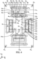
La
- la direction X correspond à la direction transversale de la couche 10 ;
- la direction Y correspond à la direction longitudinale de la couche 10 ; et
- la direction Z correspond à la direction normale à la couche 10, telle que le trièdre X, Y, Z soit un trièdre direct.
- the direction X corresponds to the transverse direction of
layer 10; - the Y direction corresponds to the longitudinal direction of
layer 10; And - the Z direction corresponds to the direction normal to
layer 10, such that the trihedron X, Y, Z is a direct trihedron.
Différentes découpes sont réalisées dans la première couche 10 afin, notamment, de créer des amorces de pliages et/ou des amorces de rupture dans la première couche 10. Ces découpes forment tout d'abord une croix 121, dans la partie centrale de la première couche 10. La croix 121 comporte quatre branches 14a1, 14b1 perpendiculaires deux à deux. Deux branches 14a1, dites longitudinales, s'étendant sensiblement selon la direction Y, sont plus longues que les deux autres branches 14b1, dites transversales, qui s'étendent sensiblement selon la direction X.Different cuts are made in the
On décrit tout d'abord les deux branches 14a1 longitudinales. Le long de chacune de ces branches 14a1 longitudinales, des découpes forment, depuis le centre de la première couche 10 vers le rebord de la première couche 10 :
- une première arête 161 cannelée, s'étendant selon la direction X
- une deuxième arête 181 cannelée, s'étendant selon la direction X, les cannelures de la deuxième arête 181 étant complémentaires des cannelures de la première
arête 161, et - une troisième arête 201, cannelée, à l'extrémité de la branche 14a1 longitudinale considérée, la troisième arête 201 s'étendant selon la direction X.
- a first
grooved edge 16 1 , extending in direction X - a second
grooved edge 18 1 , extending in direction X, the grooves of thesecond edge 18 1 being complementary to the grooves of thefirst edge 16 1 , and - a
third edge 20 1 , grooved, at the end of the longitudinal branch 14a 1 considered, thethird edge 20 1 extending in direction X.
Par cannelures complémentaires, on entend des cannelures telles qu'elles peuvent être reçues l'une dans l'autre, les dents d'une cannelure étant par exemple reçues chacune entre deux dents voisines de l'autre cannelure.By complementary splines we mean splines such that they can be received one inside the other, the teeth of one spline being for example each received between two neighboring teeth of the other spline.
En vis-à-vis de la troisième arête 201 de chaque branche 14a1 longitudinale, la première couche 10 forme une bande 221 de matière, s'étendant sensiblement selon la direction X. La bande 221 de matière s'étend de part et d'autre de la branche 14a1 longitudinale de la croix 121, la longueur de la bande 221 de matière étant supérieure à la largeur de la branche 14a1 longitudinale de la croix 121. La bande 221 de matière présente une quatrième arête 241 cannelée, en vis-à-vis de la troisième arête 201, les cannelures des troisième et quatrième arêtes 201, 241 étant complémentaires. La quatrième arête 241 s'étend sur sensiblement toute la longueur de la bande 221 de matière. Le bord de la bande 221, opposé à la quatrième arête 241 est ici rectiligne, s'étendant selon la direction X.Facing the
La troisième arête 201 cannelée s'étend de part et d'autre de l'extrémité de la branche 14a1 longitudinale, en vis-à-vis de la quatrième arête 241. Cette troisième arête 201 délimite alors partiellement le contour d'un étrier 261, auquel la bande 221 de matière est reliée par des languettes 281. Le contour de l'étrier 261 est également partiellement délimité par le prolongement, dans la direction X, de part et d'autre de la branche 14a1 longitudinale de la croix 121, de la deuxième arête 161 cannelée. L'étrier 261 forme encore une traverse 301, s'étendant sensiblement selon la direction X, deux montants 311, s'étendant sensiblement selon la direction Y, et deux coudes 321, à l'extrémité des montants 311. Les coudes 321 sont orientés l'un vers l'autre. La traverse 301 est disposée entre les deux coudes 321 et la bande de matière 221, selon la direction Y. Les coudes 321 forment ici un angle droit. L'extrémité libre 331 des coudes 321 est reliée, via une languette 341, à un palet 361. Le palet 361 est ici de forme sensiblement rectangulaire.The third
L'étrier 261 est relié par ses montants 311, au bord 381 de la première couche 101, au moyen de languettes 401.The
Par ailleurs, la première arête 161 cannelée se prolonge selon la direction X, de part et d'autre de la branche 14a1 longitudinale de la croix 121 sur laquelle elle est réalisée, en regard du prolongement de la deuxième arête 161 longitudinale délimitant partiellement l'étrier 261.Furthermore, the first
L'étrier 261 est enfin relié à la portion extrémale 1201 de la branche 14a1 longitudinale de la croix 121, par des languettes 421. La portion extrémale 1201 de la branche 14a1 longitudinale s'étend entre la deuxième arête 181 et la troisième arête 201.The
Par ailleurs, chaque branche 14b1 transversale présente une configuration sensiblement équivalente. Les éléments identiques des branches longitudinales 14a1 et transversales 14b1 portent le même signe de référence.Furthermore, each transverse branch 14b 1 has a substantially equivalent configuration. The identical elements of the longitudinal branches 14a 1 and transverse branches 14b 1 bear the same reference sign.
Ainsi, le long de chacune des branches transversales 14b1, des découpes forment, depuis le centre de la première couche 10 vers le rebord de la première couche 10 :
- une première arête 161 cannelée, s'étendant selon la direction Y,
- une deuxième arête 181 cannelée, s'étendant selon la direction Y, les cannelures de la deuxième arête 201 étant complémentaires des cannelures de la première
arête 181, et - une troisième arête 201 cannelée, formant l'extrémité de la branche 14b1 transversale considérée, la troisième arête 201 s'étendant selon la direction Y.
- a first
grooved edge 16 1 , extending in direction Y, - a second
grooved edge 18 1 , extending in the direction Y, the grooves of thesecond edge 20 1 being complementary to the grooves of thefirst edge 18 1 , and - a third
grooved edge 20 1 , forming the end of the transverse branch 14b 1 considered, thethird edge 20 1 extending in the Y direction.
En vis-à-vis de la troisième arête 201 de chaque branche transversale, la première couche 10 forme une bande 221 de matière, s'étendant sensiblement selon la direction Y. La bande 221 de matière s'étend de part et d'autre de la branche 14b1 transversale de la croix 121, la longueur de la bande 221 de matière étant supérieure à la largeur de la branche 14b1 transversale de la croix 121. La bande 221 de matière présente une quatrième arête 241 cannelée, en vis-à-vis de la troisième arête 201, les cannelures des troisième et quatrième arêtes 201, 241 étant complémentaires. La quatrième arête 241 s'étend sur sensiblement toute la longueur de la bande 221 de matière.Facing the
La troisième arête 201 cannelée s'étend de part et d'autre de l'extrémité de la branche 14b1 transversale, en vis-à-vis de la quatrième arête 241. Cette troisième arête 201 délimite alors partiellement le contour d'un carré 441 de matière. Le contour du carré 441 est également partiellement délimité par le prolongement, dans la direction Y, de part et d'autre de la branche 14b1 transversale de la croix 121, de la deuxième arête 161 cannelée.The third
Le carré 441 est relié au bord 381 de la couche 10 par des languettes 461. Par ailleurs, la première arête 161 cannelée se prolonge selon la direction Y, de part et d'autre de la branche 14b1 transversale de la croix 121 sur laquelle elle est réalisée, en regard du prolongement de la deuxième arête 161 délimitant partiellement le carré 441.The square 44 1 is connected to the
Le carré 441 est également relié à la portion extrémale 1201 de la branche 14b1 transversale de la croix 121, par des languettes 481. La portion extrémale 1201 de la branche 14b1 transversale s'étend entre la deuxième arête 181 et la troisième arête 201.The square 44 1 is also connected to the
Enfin, les bandes 221 en vis-à-vis des branches 14b1 transversales sont directement reliées au bord 381 de la couche 10 par des languettes 501.Finally, the
Il est à noter que la distance d1 entre la deuxième arête 181 et la troisième arête 201 est identique sur chaque branche 14a1, 14b1 de la croix 121. Par ailleurs, la largeur des bandes 221 est identique, la largeur étant mesurée entre la quatrième arête 241 et le côté de la bande 221 opposée à cette quatrième arête 241. Les distances d1 et d2 sont ici sensiblement égales.It should be noted that the distance d1 between the
La première couche 10 est par ailleurs munie de quatre trous 521 répartis aux angles de la première couche 10, permettant le passage d'un pion d'alignement de la première couche avec d'autres couches superposées sur cette première couche. Deux trous 541 sont également réalisés au centre de la première couche 10. La fonction de ces deux trous 541 sera décrite ultérieurement.The
La première couche 10 telle qu'elle vient d'être décrite est par exemple réalisée à partir d'une couche monolithique par découpes et/ou mises en forme. Les découpes peuvent être réalisées par tout procédé adapté au matériau de la première couche. Les découpes peuvent notamment être réalisées par découpe laser, découpe chimique, étampage. La mise en forme peut consister à ajouter de la matière, notamment par un procédé LIGA (de l'allemand « Rδntgenlithographie, Galvanoformung, Abformung » pour lithographie aux rayons X, galvanisation par électrodéposition et formage). Les étapes de découpes et/ou de mises en forme sont de préférence mises en oeuvre avant l'assemblage de la première couche 10 avec d'autres couches afin d'en faciliter la réalisation. Il en va de même des autres couches décrites ci-après.The
Sur la
Il est à noter que des découpes sont réalisées dans la deuxième couche 56, de sorte que la deuxième couche 56 présente une forme sensiblement identique à la première couche 10. La deuxième couche 56 forme par exemple une croix 122 de forme identique à la croix 121 de la première couche 10. Cependant, la croix 122, sur la deuxième couche 56, est pleine, à l'exception, ici, des deux trous 542. En particulier, la croix 122 sur la deuxième couche 56 est dépourvue d'arêtes cannelées. Plus généralement, la deuxième couche 56 dans son ensemble est dépourvue d'arêtes cannelées.It should be noted that cuts are made in the
Par ailleurs, les branches 14a2, 14b2 de la croix 122 ne sont pas reliées au bord 382 de la deuxième couche 56 par des languettes s'étendant selon la direction X. Au contraire, les branches 14a2, 14b2 sont ici reliées au bord 382 de la deuxième couche uniquement par leurs extrémités. En d'autres termes, la croix 122 sur la deuxième couche 56 est dépourvue de languettes la reliant au bord 382 de la deuxième couche 56.Furthermore, the branches 14a 2 , 14b 2 of the cross 12 2 are not connected to the
Sur la
La troisième couche 58 est ici de forme identique à la première couche 10. Ainsi, sur la
Sur la
La quatrième couche 60 est de forme sensiblement identique à la troisième couche 58.The
La quatrième couche 60 se distingue des première 10 et troisième 58 couches essentiellement en ce que les extrémités libres 334 des coudes 324 sont reliées, chacune via une languette 344 respective, à une même lame 62.The
La quatrième couche 60 est de préférence en un matériau différent des matériaux constituant les première et troisième couches 10, 58, lesquelles peuvent, le cas échant être en un même matériau. Notamment, la quatrième couche 60 peut être en un matériau plus souple que les première et troisième couches 10, 58. Alternativement ou au surplus, la quatrième couche 60 peut être plus fine que les première et troisième couches 10, 58, notamment dans le cas où toutes ces couches sont en un même matériau.The
Dans l'exemple, la quatrième couche 60 est ensuite recouverte d'une cinquième couche 64 comme illustré à la
Cette cinquième couche 64 est également fixée à la quatrième couche 60, par exemple par collage. Pour ce faire, une couche de colle ou de matière adhésive, par exemple de forme semblable à la cinquième couche 64 est interposée entre les quatrième 60 et cinquième 64 couches.This
La cinquième couche 64 est de forme identique aux première et troisième couches 10, 58. Cette cinquième couche 64 est par exemple en un matériau pouvant être brasé ou soudé, au contraire de la quatrième couche 60. Cette cinquième couche 64 ne forme pas de lame superposée à la lame 62 formée par la quatrième couche 60.The
On obtient ainsi une structure multicouche 68 sensiblement plane, visible notamment à la
Enfin, dans l'exemple de procédé décrit en regard des figures, un socle 66 est disposé sur la cinquième couche 64, comme illustré à la
Le procédé de fabrication d'un mécanisme se poursuit alors par une étape de découpe des languettes 28, 40, 42, 46, 48, 50. Cette étape aboutit à la structure multicouche 68, sensiblement plane, de la
- les étriers 26 sont détachés du bord 38 des
couches - les bandes 22 sont détachées des étriers 26 ; et
- les carrés 44 sont détachés du bord 38 des
couches
- the
stirrups 26 are detached from theedge 38 of thesuperimposed layers - the
bands 22 are detached from thestirrups 26; And - the
squares 44 are detached from theedge 38 of thesuperimposed layers extreme portions 120 of the transverse branches 14b of the cross 12.
Le procédé de fabrication se poursuit alors par une étape de déploiement selon un axe Z sensiblement normal au plan de la structure multicouche 68 plane, cette étape étant illustrée aux
La
Ici, du fait de la traction selon la direction Z, et comme illustré à la
La
Les arêtes cannelées précédemment évoquées forment ainsi, en coopération avec la deuxième couche 56, les articulations suivantes :
une première articulation 70 d'axe X entre la base de chaque branche 14a longitudinale et la portion d'extrémité correspondante ;- une deuxième
articulation 72 d'axe X entrela portion d'extrémité 120 de chaque branche 14a longitudinale et la bande 22 en vis-à-vis ; - deux troisièmes
articulations 74 d'axe X entre chaque bande 22 de matière en vis-à-vis d'une branche 14a longitudinale et l'étrier 26 associé ; - deux quatrièmes
articulations 76 d'axe X entre chaque étrier 26 et le bord 38 des différentes couches ; une cinquième articulation 78 d'axe Y entre la base de chaque branche 14b transversale et la portion d'extrémité correspondante ;une sixième articulation 80 d'axe Y entre la portion d'extrémité de chaque branche 14b transversale et la bande 22 en vis-à-vis ;- deux septièmes
articulations 82 d'axe Y entre chaque bande 22 de matière en vis-à-vis d'une branche 14b transversale et les deux carrés 44 associés ; une huitième articulation 84 d'axe Y entre chaque carré 44 et le bord 38 des différentes couches.
- a
first articulation 70 of axis X between the base of each longitudinal branch 14a and the corresponding end portion; - a
second articulation 72 of axis X between theend portion 120 of each longitudinal branch 14a and thestrip 22 facing each other; - two
third articulations 74 of axis X between eachstrip 22 of material facing a longitudinal branch 14a and the associatedstirrup 26; - two
fourth joints 76 of axis X between each stirrup 26 and theedge 38 of the different layers; - a
fifth articulation 78 with axis Y between the base of each transverse branch 14b and the corresponding end portion; - a
sixth articulation 80 of axis Y between the end portion of each transverse branch 14b and thestrip 22 facing each other; - two
seventh joints 82 of axis Y between eachstrip 22 of material facing a transverse branch 14b and the two associatedsquares 44; - an
eighth articulation 84 with axis Y between each square 44 and theedge 38 of the different layers.
Ainsi, en choisissant des orientations perpendiculaires des articulations, on forme ici un montage de Sarrus 86 (de l'anglais « Sarrus linkage »). Ce montage de Sarrus est un exemple particulier d'échafaudage de montage (de l'anglais « mounting scaffold ») pouvant être mis en oeuvre dans le procédé.Thus, by choosing perpendicular orientations of the joints, we form here a
Un tel échafaudage de montage est réalisé par la structure multicouche, en plus de la structure d'intérêt que l'on cherche à réaliser. Cet échafaudage de montage permet de relier les différents mouvements nécessaires au déploiement de la structure multicouche, de manière que ce déploiement puisse être réalisé en agissant sur la structure multicouche selon un unique degré de liberté. Cet échafaudage de montage facilite ainsi l'étape de déploiement.Such mounting scaffolding is produced by the multilayer structure, in addition to the structure of interest that we seek to achieve. This assembly scaffolding makes it possible to connect the different movements necessary for the deployment of the multi-layer structure, so that this deployment can be carried out by acting on the multilayer structure according to a single degree of freedom. This assembly scaffolding thus facilitates the deployment stage.
Le montage de Sarrus 86 ainsi réalisé permet ainsi, en tirant sur une partie de la structure multicouche 68 selon la direction Z, de provoquer un redressement des étriers 26. Le redressement des étriers 26 s'accompagne d'un rapprochement des lames 62 du support 66. Le redressement des étriers 26 provoque également un pivotement des lames 62, de sorte que leur largeur s'étende selon une direction normale au plan de la structure multicouche 68 plane, la longueur et l'épaisseur des lames s'étendant sensiblement dans un plan parallèle au plan de la structure multicouche 68, plane. On obtient ainsi, à partir d'une lame adaptée initialement à osciller dans un plan normal au plan de la structure multicouche 68 plane, une lame adaptée à osciller dans un plan parallèle au plan de la structure multicouche 68.The assembly of
On obtient ainsi une structure multicouche déployée 88, telle qu'illustrée à la
En outre, à cette étape ou après cette étape de blocage, les palets 36 fixés aux extrémités des lames 62 peuvent être fixés à des masses 92, ici réalisées sous forme de poutrelles. Ceci peut notamment être réalisé par brasage. Dans ce cas, une plaquette métallique peut être collée à chaque extrémité des masses 92, permettant ainsi la fixation par brasage.In addition, at this step or after this blocking step, the
La
Enfin, la
Dans l'exemple illustré, les lames 62 sont plus souples que les masses 92 et les palets 36. Notamment les lames 62 sont en un matériau plus souple que les masses 92 et, éventuellement, les palets 36. Le mécanisme 100 flexible peut ainsi former un oscillateur.In the example illustrated, the
Il est à noter ici que les lames 62 sont orientées de telle sorte qu'elles permettent au mécanisme flexible 100 d'osciller dans un plan s'étendant sensiblement selon les directions X et Y. Au contraire, dans la structure multicouche 68 plane, les lames 62 étaient orientées de telle sorte qu'elles avaient tendance à osciller dans un plan normal à ce plan.It should be noted here that the
Les lames 62 sont par exemple en l'un parmi le silicium, le verre, le saphir ou alumine, le diamant, notamment le diamant synthétique, en particulier le diamant synthétique obtenu par procédé de déposition chimique en phase vapeur, le titane, un alliage de titane, notamment un alliage de la famille des Gum metal ® et un alliage de la famille des élinvars, en particulier l'Elinvar ®, le Nivarox ®, le Thermelast ®, le NI-Span-C ® et le Précision C ®.The
Ces matériaux présentent en effet l'avantage que leur module d'Young est très peu sensible aux variations de température. Ceci est particulièrement avantageux dans le domaine horloger, par exemple, où le mécanisme, notamment le régulateur, doit garder sa précision, même en cas de variations de température.These materials have the advantage that their Young's modulus is very insensitive to temperature variations. This is particularly advantageous in the watchmaking field, for example, where the mechanism, in particular the regulator, must maintain its precision, even in the event of temperature variations.
Les Gum métal® sont des matériaux comprenant : 23 % de niobium ; 0,7 % de tantale ; 2 % de zirconium ; 1 % d'oxygène ; facultativement du vanadium ; et facultativement du hafnium.Gum metal ® are materials comprising: 23% niobium; 0.7% tantalum; 2% zirconium; 1% oxygen; optionally vanadium; and optionally hafnium.
Les alliages élinvars sont des alliages d'acier au nickel comprenant du nickel et du chrome qui sont très peu sensible aux températures. L'Elinvar ®, en particulier, est un alliage d'acier au nickel, comprenant 59 % de fer, 36 % de nickel et 5 % de chrome.Elinvar alloys are nickel steel alloys comprising nickel and chromium which are very insensitive to temperatures. Elinvar ® , in particular, is a nickel steel alloy, comprising 59% iron, 36% nickel and 5% chromium.
le NI-Span-C ® comprend entre 41,0 et 43,5 % de nickel et de cobalt ; entre 4,9 et 5,75 % de chrome ; entre 2,20 et 2,75 % de titane ; entre 0,30 et 0,80 % d'aluminium ; au plus 0,06 % de carbone ; au plus 0,80 % de manganèse ; au plus 1 % de silicium ; au plus 0,04 % de soufre ; au plus de 0,04 % de phosphore ; et le complément à 100 % en fer.NI-Span-C ® includes between 41.0 and 43.5% nickel and cobalt; between 4.9 and 5.75% chromium; between 2.20 and 2.75% titanium; between 0.30 and 0.80% aluminum; at most 0.06% carbon; at most 0.80% manganese; at most 1% silicon; at most 0.04% sulfur; at most 0.04% phosphorus; and the 100% iron supplement.
Le Précision C ® comprend : 42 % de nickel ; 5,3 % de chrome ; 2,4 % de titane ; 0,55 % d'aluminium ; 0,50 % de silicium ; 0,40 % de manganèse ; 0,02 % de carbone ; et le complément à 100 % en fer.Précision C ® includes: 42% nickel; 5.3% chromium; 2.4% titanium; 0.55% aluminum; 0.50% silicon; 0.40% manganese; 0.02% carbon; and the 100% iron supplement.
Le Nivarox ® comprend : entre 30 et 40 % de nickel ; entre 0,7 et 1,0% de béryllium ; entre 6 et 9 % de molybdène et/ou 8 % de chrome ; de manière facultative, 1 % de titane ; entre 0,7 et 0,8 % de manganèse ; entre 0,1 et 0,2 % de silicium ; du carbone, jusqu'à 0,2 % ; et le complément en fer.Nivarox ® includes: between 30 and 40% nickel; between 0.7 and 1.0% beryllium; between 6 and 9% molybdenum and/or 8% chromium; optionally, 1% titanium; between 0.7 and 0.8% manganese; between 0.1 and 0.2% silicon; carbon, up to 0.2%; and iron supplement.
Le Thermelast ® comprend : 42,5 % de nickel ; moins de 1 % de silicium ; 5,3 % de chrome ; moins de 1 % d'aluminium ; moins de 1 % de manganèse ; 2,5 % de titane ; et 48 % de fer.Thermelast ® includes: 42.5% nickel; less than 1% silicon; 5.3% chromium; less than 1% aluminum; less than 1% manganese; 2.5% titanium; and 48% iron.
Toutes les compositions ci-dessus sont indiquées en pourcentages massiques.All compositions above are indicated in mass percentages.
La ou les lames présentent avantageusement une épaisseur supérieure ou égale à 1 µm, de préférence supérieure ou égale à 5 µm, et/ou inférieure ou égale à 30 µm, de préférence inférieure ou égale à 20 µm, de préférence inférieure ou égale à 15 µm.The blade(s) advantageously have a thickness greater than or equal to 1 µm, preferably greater than or equal to 5 µm, and/or less than or equal to 30 µm, preferably less than or equal to 20 µm, preferably less than or equal to 15 µm.
La ou les lames peuvent encore présenter une largeur supérieure ou égale à 0,1 mm et/ou inférieure ou égale à 2 mm, de préférence inférieure ou égale à 1 mm.The blade(s) may also have a width greater than or equal to 0.1 mm and/or less than or equal to 2 mm, preferably less than or equal to 1 mm.
La ou les lames peuvent aussi présenter une longueur comprise, par exemple, entre 5 et 13 mm.The blade(s) may also have a length of, for example, between 5 and 13 mm.
La ou chaque lame 62 peut encore présenter un rapport d'aspect défini comme le rapport entre la largeur et l'épaisseur de la lame, supérieur à 10, de préférence supérieur à 25.The or each
Les masses 92 sont par exemple en l'un parmi le tungstène, le molybdène, l'or, l'argent, le tantale, le platine, les alliages comprenant ces éléments et un matériau polymère chargé de particules de densité supérieure à dix, notamment de particules de tungstène. Ces matériaux sont en effet lourds. Dans le cas d'un mécanisme 100 formant oscillateur, cela permet d'avoir masses 92 de dimensions réduites mais avec un poids relativement important.The
Les palets 36, et donc les première, troisième et cinquième couches 10, 58, 64 sont par exemple en matériaux polymères. Ces palets 36 peuvent permettre d'améliorer la résistance du mécanisme 100 aux chocs.The
Comme indiqué précédemment, le mécanisme 100 peut avantageusement former un oscillateur. Dans ce cas, l'une des masses 92 peut former un bâti ou être fixée rigidement à un bâti, par rapport auquel l'autre masse 92 oscille. En l'espèce, dans ce cas, l'une des masses 92 oscille selon un mouvement de translation circulaire T par rapport à l'autre masse 92. Dans un tel cas, un rapport d'aspect élevé de la ou de chaque lame 62 permet notamment de limiter les modes d'oscillation de cette ou ces lames 62 hors plan.As indicated previously, the
Avantageusement, la ou chaque lame 62 présente une longueur libre L supérieure ou égale au tiers de la largeur de la lame 62. Dans le cas où la lame est fixée à une seule masse, la longueur libre est définie comme étant la longueur de la lame qui n'est pas en contact avec la masse. Dans le cas où la lame est fixée à deux masses, la longueur libre s'entend de la longueur de la lame entre les deux masses, qui n'est pas en contact avec l'une ou l'autre des masses. De préférence, sur la longueur libre de la lame 62, cette dernière n'est en contact avec aucun autre élément du mécanisme intégrant la ou les lames 62.Advantageously, the or each
Un mécanisme flexible du type de celui de la
De manière connue, une pièce d'horlogerie 200 telle qu'une montre illustrée à la
un boîtier 202,- un mouvement horloger 203 contenu dans le boîtier 202,
- généralement,
un remontoir 204, un cadran 205,- un verre 206 recouvrant le cadran 205,
- un indicateur de temps 207, comprenant par exemple deux aiguilles 207a, 207b respectivement pour les heures et les minutes, disposé entre le verre 206 et le cadran 205 et actionné par le mouvement horloger 203.
- a
box 202, - a
watch movement 203 contained in thecase 202, - generally, a
winder 204, - a
dial 205, - a
glass 206 covering thedial 205, - a
time indicator 207, comprising for example twohands glass 206 and thedial 205 and actuated by thewatch movement 203.
Comme représenté schématiquement sur la
un dispositif 208 de stockage d'énergie mécanique, généralement un ressort de barillet,une transmission mécanique 209 mue par le dispositif 208 de stockage d'énergie mécanique,- l'indicateur de temps 207 susmentionné,
- un organe de distribution d'énergie 210 (par exemple une roue d'échappement),
- une ancre 211 adaptée pour séquentiellement retenir et libérer l'organe de
distribution d'énergie 210, un régulateur 212, qui est un mécanisme comportant un organe réglant oscillant contrôlant l'ancre 211 pour la déplacer régulièrement de façon que l'organe de distribution d'énergie soit déplacé pas à pas à intervalles de temps constants, et, éventuellement,- un organe de découplage 213, qui est interposé entre le régulateur 212
et l'ancre 211.
- a mechanical
energy storage device 208, generally a barrel spring, - a
mechanical transmission 209 driven by the mechanicalenergy storage device 208, - the
aforementioned time indicator 207, - an energy distribution member 210 (for example an escape wheel),
- an
anchor 211 adapted to sequentially retain and release theenergy distribution member 210, - a
regulator 212, which is a mechanism comprising an oscillating regulating member controlling theanchor 211 to move it regularly so that the energy distribution member is moved step by step at constant time intervals, and, optionally, - a
decoupling member 213, which is interposed between theregulator 212 and theanchor 211.
L'invention ne se limite pas au seul mode de réalisation décrit ci-avant en regard des figures, mais est, au contraire, susceptible de nombreuses variantes accessibles à l'homme de l'art.The invention is not limited to the single embodiment described above with reference to the figures, but is, on the contrary, capable of numerous variants accessible to those skilled in the art.
Tout d'abord, dans l'exemple de procédé décrit, les masses sont fixées sur les lames, plus précisément aux extrémités des lames, après le déploiement de la structure multicouche. Dans l'exemple décrit, cette fixation est réalisée à l'aide d'un brasage. Alternativement, cependant, les masses sont fixées à la ou aux lames, en particulier aux extrémités de ces lames, par surmoulage, serrage, clipsage, collage, soudage, notamment soudage par point, en particulier soudage par point au laser, ou tout autre procédé accessible à l'homme de l'art.First of all, in the example of the method described, the masses are fixed on the blades, more precisely at the ends of the blades, after the deployment of the multilayer structure. In the example described, this fixing is carried out using brazing. Alternatively, however, the masses are fixed to the blade(s), in particular at the ends of these blades, by overmolding, clamping, clipping, gluing, welding, in particular spot welding, in particular laser spot welding, or any other process accessible to those skilled in the art.
Les masses peuvent être rapportées sur la structure multicouche déployée, sous forme d'une découpe dans une couche de matériau supplémentaire que l'on superpose à la structure multicouche déployée. La découpe dans la couche de matériau supplémentaire peut notamment former des logements de réception des extrémités des lames flexibles, en particulier des palets fixés aux extrémités des lames, la réception étant alors, de préférence, réalisée avec serrage.The masses can be reported on the deployed multilayer structure, in the form of a cutout in an additional layer of material which is superimposed on the deployed multilayer structure. The cutting in the layer of additional material can in particular form housings for receiving the ends of the flexible blades, in particular the pucks fixed to the ends of the blades, the reception then being, preferably, carried out with clamping.
Également, selon une variante, les masses peuvent être formées par la structure multicouche. Les masses sont alors disposées en vis-à-vis des extrémités des lames ou des palets fixés à ces extrémités au moment du déploiement de la structure multicouche.Also, according to a variant, the masses can be formed by the multilayer structure. The masses are then arranged opposite the ends of the blades or pallets fixed at these ends at the time of deployment of the multilayer structure.
Par ailleurs, dans l'exemple de procédé décrit, celui-ci comporte une étape de blocage de la structure en position déployée. Cette étape est a priori facultative. Elle est toutefois préférée quand d'autres manipulations de la structure en position déployée sont souhaitées pour aboutir au mécanisme. Dans le cas où un tel blocage est à réaliser, celui-ci peut être obtenu par tout moyen accessible à l'homme de l'art, notamment par collage, surmoulage, brasage, clipsage, soudage, notamment soudage par point, en particulier soudage par point au laser ou, plus généralement, par fixation ensemble d'éléments de la structure en position déployée.Furthermore, in the example of the method described, it includes a step of blocking the structure in the deployed position. This step is a priori optional. It is however preferred when other manipulations of the structure in the deployed position are desired to achieve the mechanism. In the case where such blocking is to be carried out, this can be obtained by any means accessible to those skilled in the art, in particular by bonding, overmolding, soldering, clipping, welding, in particular spot welding, in particular welding by laser point or, more generally, by fixing together elements of the structure in the deployed position.
De plus, le procédé de fabrication d'un mécanisme peut comporter une étape d'assemblage de nombreuses couches les unes sur les autres. De préférence, cependant, le nombre de couches de matériau superposées est compris entre dix et cinquante.In addition, the method of manufacturing a mechanism may include a step of assembling numerous layers on top of each other. Preferably, however, the number of superimposed layers of material is between ten and fifty.
Enfin, dans l'exemple décrit, un unique mécanisme 100 est obtenu par mise en oeuvre du procédé. Cependant, de manière avantageuse, il peut être prévu qu'un même empilement de couches permette la formation d'une pluralité de structures multicouches et/ou d'une pluralité de structures déployées. On peut ainsi améliorer sensiblement le rendement du procédé de fabrication d'un mécanisme.Finally, in the example described, a
Enfin, les arêtes cannelées évoquées dans l'exemple décrit peuvent être remplacées par des amorces de pliage. Notamment, les amorces de pliages peuvent être réalisées par des découpes partielles des couches. Les découpes partielles peuvent consister en des découpes en pointillés et/ou en une découpe sur une partie seulement de l'épaisseur des couches. Dans le cas d'une découpe sur une partie seulement de l'épaisseur des couches, la découpe partielle peut éventuellement être continue. Une découpe totale des couches peut également être envisagée.Finally, the grooved edges mentioned in the example described can be replaced by folding tips. In particular, the beginnings of folding can be made by partial cutting of the layers. Partial cuts may consist of dotted cuts and/or cutting only part of the thickness of the layers. In the case of cutting only part of the thickness of the layers, the partial cutting can possibly be continuous. Complete cutting of the layers can also be considered.
Claims (15)
- Method for manufacturing a timepiece oscillator (100) comprising the steps of:i. assembling flat layers (10; 56; 58; 60; 64) together to form a substantially flat multilayer structure (68);ii. deploying the multilayer structure in a direction (Z) substantially normal to the flat layers (10; 56; 58; 60; 64);method wherein at least a first layer (60) of said layers (10; 56; 58; 60; 64) forms at least one flexible blade (62) in the timepiece oscillator (100), the blade or blades (62) being fixed, in the timepiece oscillator (100), to at least one mass (92), preferably to two masses (92), the or each mass (92) being more rigid than the blade or blades (62), the blade or blades (62) being fixed to the or to each mass (92) in a step subsequent to step ii).
- Method according to claim 1, wherein each blade (62) has, in the timepiece oscillator (100), a free length (L) greater than one third of the width of the blade (62) in question, the free length (L) being defined as being:- the length of the blade (62) which is not in contact with the mass (92), in the case where the blade (62) is fixed to one mass (92), or- the length of the blade (62) extending between the two masses (92) without being in contact with one of the masses (92), in the case where the blade (62) is fixed to two masses (92),the or each blade (62) preferably not being in contact with any other element of the timepiece oscillator (100) along the free length (L).
- Method according to claim 1 or 2, comprising a step iii) subsequent to step ii), consisting of locking the multilayer structure in the deployed position (88), wherein, preferably, in step iii), the structure is locked in the deployed position (88) by at least one among: an overmolding, brazing, clipping, gluing, welding, particularly spot welding, more particularly laser spot welding, and clamping, of at least a part of the timepiece oscillator, in particular of at least one hinge of the timepiece oscillator.
- Method according to any one of the preceding claims, wherein the or each mass (92) is attached to an end, preferably to a respective end, of one of said at least one blade (62).
- Method according to any one of the preceding claims, wherein the or each mass (92) is fixed to the blade (62) or to each blade (62) by:- overmolding;- brazing;- clipping;- gluing;- welding, particularly spot welding, more particularly laser spot welding;- clamping.
- Method according to any one of the preceding claims, wherein the mass or masses (92) are created by at least one of the flat layers (10; 56; 58; 60; 64) assembled in step i).
- Method according to any one of the preceding claims, wherein the mass or masses (92) are of one among: tungsten, molybdenum, gold, silver, tantalum, platinum, alloys comprising these elements and a polymer material loaded with particles of a density greater than ten, in particular tungsten particles.
- Method according to any one of the preceding claims, wherein the blade or blades (62) are of one among: silicon, glass, sapphire, diamond, particularly synthetic diamond, more particularly synthetic diamond obtained by a chemical vapor deposition process, titanium, a titanium alloy, particularly an alloy of the Gum metal® family and an alloy of the elinvar family, more particularly Elinvar®, Nivarox®, Thermelast® , Ni-Span-C®, Precision C®.
- Method according to any one of the preceding claims, wherein- in step i), ten to fifty flat layers (10; 56; 58; 60; 64) are assembled together; and/or- the blade or blades (62) have a width, a thickness, and an aspect ratio defined as being equal to the ratio of the width of the blade (62) to the thickness of the blade (62), the aspect ratio of each blade being greater than 10, preferably greater than 25; and/or- the blade or blades (62) have a thickness greater than or equal to 1 µm, preferably greater than 5 µm, and/or less than or equal to 30 µm, preferably less than or equal to 20 µm, more preferably less than or equal to 15 µm;- the blade or blades (62) have a width greater than or equal to 0.1 mm and/or less than or equal to 2 mm, preferably less than or equal to 1 mm.
- Method according to any one of the preceding claims, wherein the substantially flat multilayer structure (68) forms at least one mounting scaffold (86), the method comprising a step iv), preferably subsequent to step iii) where appropriate, consisting of detaching the structure in the deployed position (88), from the at least one mounting scaffold (86).
- Method according to any one of the preceding claims, wherein each layer (10; 56; 58; 60; 64) undergoes a machining step, preferably before its assembling, in particular laser cutting, industrial etching, stamping, milling, electrical discharge machining, and/or a shaping step, particularly a shaping step by adding material, more particularly a shaping step by LIGA or by injection molding.
- Method according to any one of the preceding claims, wherein a plurality of substantially flat multilayer structures (68), respectively structures in the deployed position (88), are obtained in step ii), respectively in step iii), from a single assembling of layers in step i).
- Method according to any one of the preceding claims, wherein the or each blade (62) is of a more flexible material than the or each mass (92) which is fixed to said blade (62).
- Timepiece oscillator at least partly made by implementing a method according to any one of claims 1 to 13.
- Timepiece movement (203) for a timepiece (200), comprising a timepiece oscillator according to claim 14.
Applications Claiming Priority (2)
| Application Number | Priority Date | Filing Date | Title |
|---|---|---|---|
| FR1753603A FR3065542B1 (en) | 2017-04-25 | 2017-04-25 | METHOD FOR MANUFACTURING A MECHANISM |
| PCT/EP2018/060505 WO2018197516A1 (en) | 2017-04-25 | 2018-04-24 | Method for manufacturing a mechanism |
Publications (2)
| Publication Number | Publication Date |
|---|---|
| EP3615470A1 EP3615470A1 (en) | 2020-03-04 |
| EP3615470B1 true EP3615470B1 (en) | 2024-04-24 |
Family
ID=59031227
Family Applications (1)
| Application Number | Title | Priority Date | Filing Date |
|---|---|---|---|
| EP18717965.0A Active EP3615470B1 (en) | 2017-04-25 | 2018-04-24 | Method for manufacturing a timepiece oscillator |
Country Status (6)
| Country | Link |
|---|---|
| US (1) | US11467542B2 (en) |
| EP (1) | EP3615470B1 (en) |
| JP (1) | JP7184800B2 (en) |
| CN (1) | CN111278765A (en) |
| FR (1) | FR3065542B1 (en) |
| WO (1) | WO2018197516A1 (en) |
Families Citing this family (1)
| Publication number | Priority date | Publication date | Assignee | Title |
|---|---|---|---|---|
| FR3094803B1 (en) | 2019-04-05 | 2021-04-23 | Lvmh Swiss Mft Sa | Spherical oscillator for watch mechanism |
Family Cites Families (12)
| Publication number | Priority date | Publication date | Assignee | Title |
|---|---|---|---|---|
| US3763544A (en) * | 1972-04-17 | 1973-10-09 | Gen Electric | Method of manufacturing type fingers |
| DE69904937T2 (en) * | 1998-07-03 | 2003-08-28 | Citizen Watch Co Ltd | METHOD FOR PRODUCING HANDS FOR ELECTRONIC ANALOG WATCHES |
| EP1921517B1 (en) * | 2006-11-09 | 2010-05-12 | ETA SA Manufacture Horlogère Suisse | Assembly component comprising fork-shaped elastic structures and timepiece incorporating this component |
| EP1921518B1 (en) * | 2006-11-09 | 2010-05-26 | ETA SA Manufacture Horlogère Suisse | Assembly component comprising overlaid blade-shaped elastic structures and timepiece equipped with this component |
| DE602006011760D1 (en) * | 2006-11-09 | 2010-03-04 | Eta Sa Mft Horlogere Suisse | Mounting element comprising two rows of expandable structures, and clock comprising this element |
| EP2105806B1 (en) * | 2008-03-27 | 2013-11-13 | Sowind S.A. | Escapement mechanism |
| EP2400353A1 (en) * | 2010-06-22 | 2011-12-28 | The Swatch Group Research and Development Ltd. | Hand for a timepiece |
| WO2012109559A1 (en) | 2011-02-11 | 2012-08-16 | President And Fellows Of Harvard College | Monolithic fabrication of three-dimensional structures |
| EP2831677B1 (en) * | 2012-03-29 | 2016-05-25 | Nivarox-FAR S.A. | Flexible escapement mechanism |
| US10376326B2 (en) * | 2013-08-04 | 2019-08-13 | President And Fellows Of Harvard College | Pop-up laminate structures with integrated electronics |
| EP3032351A1 (en) | 2014-12-09 | 2016-06-15 | LVMH Swiss Manufactures SA | Timepiece mechanism, timepiece movement and timepiece having such a mechanism |
| US10528005B2 (en) * | 2014-12-09 | 2020-01-07 | Lvmh Swiss Manufactures Sa | Mechanism for a timepiece and timepiece having such a mechanism |
-
2017
- 2017-04-25 FR FR1753603A patent/FR3065542B1/en active Active
-
2018
- 2018-04-24 US US16/608,319 patent/US11467542B2/en active Active
- 2018-04-24 EP EP18717965.0A patent/EP3615470B1/en active Active
- 2018-04-24 WO PCT/EP2018/060505 patent/WO2018197516A1/en unknown
- 2018-04-24 JP JP2019557768A patent/JP7184800B2/en active Active
- 2018-04-24 CN CN201880042373.1A patent/CN111278765A/en active Pending
Also Published As
| Publication number | Publication date |
|---|---|
| JP7184800B2 (en) | 2022-12-06 |
| US20200192299A1 (en) | 2020-06-18 |
| JP2020517949A (en) | 2020-06-18 |
| EP3615470A1 (en) | 2020-03-04 |
| US11467542B2 (en) | 2022-10-11 |
| CN111278765A (en) | 2020-06-12 |
| FR3065542A1 (en) | 2018-10-26 |
| FR3065542B1 (en) | 2019-07-12 |
| WO2018197516A1 (en) | 2018-11-01 |
Similar Documents
| Publication | Publication Date | Title |
|---|---|---|
| EP2104006B1 (en) | Single-body double spiral and method for manufacturing same | |
| EP2196868B1 (en) | Hairspring with curve elevation made from a silicon-based material | |
| EP2407831B1 (en) | Hairspring for oscillator balance of a clock piece and method for manufacturing same | |
| EP2105807B1 (en) | Monobloc elevated curve spiral and method for manufacturing same | |
| EP2485095B1 (en) | Composite balance | |
| EP2145237B1 (en) | Timepiece component and method for making same | |
| EP2998800B1 (en) | Timepiece component with flexible pivot | |
| EP2656151B1 (en) | Assembly of a component which does not have a plastic domain | |
| CH699882A2 (en) | Elevated curve hairspring e.g. breguet hairspring, for use in timepiece, has lifting device arranged between external layer of spring and terminal curve so as to increase concentric development of hairspring | |
| EP2952971B1 (en) | Pallet for escapement mechanism of a watch movement | |
| CH700640A1 (en) | TIMEPIECE leaner and ENHANCED. | |
| EP3502784A1 (en) | Timepiece resonator with flexible guide | |
| WO2009115470A1 (en) | Integral hairspring made of a silicon-based material and method for making same | |
| EP2743781A1 (en) | Device for assembly by locking a joint | |
| EP3561607A1 (en) | Collision protection of a resonator mechanism with rotatable flexible guiding | |
| EP2690506A1 (en) | Anti-tripping clock hairspring | |
| EP3615470B1 (en) | Method for manufacturing a timepiece oscillator | |
| EP2570868B1 (en) | Part for a clockwork, clockwork and timepiece | |
| EP3037893B1 (en) | Micromechanical or clock component with flexible guidance | |
| EP3042250B1 (en) | Timepiece mobile with clearance compensation | |
| EP3786720B1 (en) | Clock component for receiving an organ by insertion | |
| EP3432082B1 (en) | Regulating mechanism | |
| EP3948433B1 (en) | Spherical oscillator for a timepiece mechanism | |
| EP3391154B1 (en) | Oscillating system for timepiece | |
| CH708553B1 (en) | Mobile watchmaker to catch up game. |
Legal Events
| Date | Code | Title | Description |
|---|---|---|---|
| STAA | Information on the status of an ep patent application or granted ep patent |
Free format text: STATUS: UNKNOWN |
|
| STAA | Information on the status of an ep patent application or granted ep patent |
Free format text: STATUS: THE INTERNATIONAL PUBLICATION HAS BEEN MADE |
|
| PUAI | Public reference made under article 153(3) epc to a published international application that has entered the european phase |
Free format text: ORIGINAL CODE: 0009012 |
|
| STAA | Information on the status of an ep patent application or granted ep patent |
Free format text: STATUS: REQUEST FOR EXAMINATION WAS MADE |
|
| 17P | Request for examination filed |
Effective date: 20191025 |
|
| AK | Designated contracting states |
Kind code of ref document: A1 Designated state(s): AL AT BE BG CH CY CZ DE DK EE ES FI FR GB GR HR HU IE IS IT LI LT LU LV MC MK MT NL NO PL PT RO RS SE SI SK SM TR |
|
| AX | Request for extension of the european patent |
Extension state: BA ME |
|
| DAV | Request for validation of the european patent (deleted) | ||
| DAX | Request for extension of the european patent (deleted) | ||
| STAA | Information on the status of an ep patent application or granted ep patent |
Free format text: STATUS: EXAMINATION IS IN PROGRESS |
|
| 17Q | First examination report despatched |
Effective date: 20211025 |
|
| GRAP | Despatch of communication of intention to grant a patent |
Free format text: ORIGINAL CODE: EPIDOSNIGR1 |
|
| STAA | Information on the status of an ep patent application or granted ep patent |
Free format text: STATUS: GRANT OF PATENT IS INTENDED |
|
| INTG | Intention to grant announced |
Effective date: 20231115 |
|
| GRAS | Grant fee paid |
Free format text: ORIGINAL CODE: EPIDOSNIGR3 |
|
| GRAA | (expected) grant |
Free format text: ORIGINAL CODE: 0009210 |
|
| STAA | Information on the status of an ep patent application or granted ep patent |
Free format text: STATUS: THE PATENT HAS BEEN GRANTED |
|
| AK | Designated contracting states |
Kind code of ref document: B1 Designated state(s): AL AT BE BG CH CY CZ DE DK EE ES FI FR GB GR HR HU IE IS IT LI LT LU LV MC MK MT NL NO PL PT RO RS SE SI SK SM TR |
|
| REG | Reference to a national code |
Ref country code: GB Ref legal event code: FG4D Free format text: NOT ENGLISH |
|
| REG | Reference to a national code |
Ref country code: CH Ref legal event code: EP |