EP3615470B1 - Verfahren zur herstellung eines uhrenoszillators - Google Patents
Verfahren zur herstellung eines uhrenoszillators Download PDFInfo
- Publication number
- EP3615470B1 EP3615470B1 EP18717965.0A EP18717965A EP3615470B1 EP 3615470 B1 EP3615470 B1 EP 3615470B1 EP 18717965 A EP18717965 A EP 18717965A EP 3615470 B1 EP3615470 B1 EP 3615470B1
- Authority
- EP
- European Patent Office
- Prior art keywords
- blade
- layer
- mass
- masses
- blades
- Prior art date
- Legal status (The legal status is an assumption and is not a legal conclusion. Google has not performed a legal analysis and makes no representation as to the accuracy of the status listed.)
- Active
Links
- 238000000034 method Methods 0.000 title claims description 50
- 238000004519 manufacturing process Methods 0.000 title claims description 19
- 239000000463 material Substances 0.000 claims description 52
- 238000003466 welding Methods 0.000 claims description 22
- 230000008569 process Effects 0.000 claims description 14
- 229910045601 alloy Inorganic materials 0.000 claims description 11
- 239000000956 alloy Substances 0.000 claims description 11
- RTAQQCXQSZGOHL-UHFFFAOYSA-N Titanium Chemical compound [Ti] RTAQQCXQSZGOHL-UHFFFAOYSA-N 0.000 claims description 10
- 238000007493 shaping process Methods 0.000 claims description 10
- 229910000942 Elinvar Inorganic materials 0.000 claims description 9
- 239000010432 diamond Substances 0.000 claims description 9
- 229910003460 diamond Inorganic materials 0.000 claims description 9
- 239000010703 silicon Substances 0.000 claims description 9
- 229910052710 silicon Inorganic materials 0.000 claims description 9
- 238000005219 brazing Methods 0.000 claims description 8
- 239000010936 titanium Substances 0.000 claims description 8
- 229910052719 titanium Inorganic materials 0.000 claims description 8
- BASFCYQUMIYNBI-UHFFFAOYSA-N platinum Chemical compound [Pt] BASFCYQUMIYNBI-UHFFFAOYSA-N 0.000 claims description 7
- 238000004026 adhesive bonding Methods 0.000 claims description 6
- 239000002245 particle Substances 0.000 claims description 6
- WFKWXMTUELFFGS-UHFFFAOYSA-N tungsten Chemical compound [W] WFKWXMTUELFFGS-UHFFFAOYSA-N 0.000 claims description 6
- 229910052721 tungsten Inorganic materials 0.000 claims description 6
- 239000010937 tungsten Substances 0.000 claims description 6
- ZOKXTWBITQBERF-UHFFFAOYSA-N Molybdenum Chemical compound [Mo] ZOKXTWBITQBERF-UHFFFAOYSA-N 0.000 claims description 5
- 229910001075 Nivarox Inorganic materials 0.000 claims description 5
- 239000011521 glass Substances 0.000 claims description 5
- GUVRBAGPIYLISA-UHFFFAOYSA-N tantalum atom Chemical compound [Ta] GUVRBAGPIYLISA-UHFFFAOYSA-N 0.000 claims description 5
- 229910000787 Gum metal Inorganic materials 0.000 claims description 4
- BQCADISMDOOEFD-UHFFFAOYSA-N Silver Chemical compound [Ag] BQCADISMDOOEFD-UHFFFAOYSA-N 0.000 claims description 4
- 229910052750 molybdenum Inorganic materials 0.000 claims description 4
- 239000011733 molybdenum Substances 0.000 claims description 4
- 229910052715 tantalum Inorganic materials 0.000 claims description 4
- 238000005229 chemical vapour deposition Methods 0.000 claims description 3
- PCHJSUWPFVWCPO-UHFFFAOYSA-N gold Chemical compound [Au] PCHJSUWPFVWCPO-UHFFFAOYSA-N 0.000 claims description 3
- 229910052737 gold Inorganic materials 0.000 claims description 3
- 239000010931 gold Substances 0.000 claims description 3
- 238000003698 laser cutting Methods 0.000 claims description 3
- 238000003754 machining Methods 0.000 claims description 3
- 229910052697 platinum Inorganic materials 0.000 claims description 3
- 239000002861 polymer material Substances 0.000 claims description 3
- 229910052594 sapphire Inorganic materials 0.000 claims description 3
- 239000010980 sapphire Substances 0.000 claims description 3
- 229910052709 silver Inorganic materials 0.000 claims description 3
- 239000004332 silver Substances 0.000 claims description 3
- 229910001069 Ti alloy Inorganic materials 0.000 claims description 2
- 238000005530 etching Methods 0.000 claims description 2
- 238000001746 injection moulding Methods 0.000 claims description 2
- 238000003801 milling Methods 0.000 claims description 2
- 238000009760 electrical discharge machining Methods 0.000 claims 1
- 230000007246 mechanism Effects 0.000 description 27
- 238000005520 cutting process Methods 0.000 description 17
- PXHVJJICTQNCMI-UHFFFAOYSA-N Nickel Chemical compound [Ni] PXHVJJICTQNCMI-UHFFFAOYSA-N 0.000 description 16
- 210000002105 tongue Anatomy 0.000 description 11
- XEEYBQQBJWHFJM-UHFFFAOYSA-N Iron Chemical compound [Fe] XEEYBQQBJWHFJM-UHFFFAOYSA-N 0.000 description 10
- XUIMIQQOPSSXEZ-UHFFFAOYSA-N Silicon Chemical compound [Si] XUIMIQQOPSSXEZ-UHFFFAOYSA-N 0.000 description 9
- 229910052759 nickel Inorganic materials 0.000 description 8
- 230000000903 blocking effect Effects 0.000 description 7
- VYZAMTAEIAYCRO-UHFFFAOYSA-N Chromium Chemical compound [Cr] VYZAMTAEIAYCRO-UHFFFAOYSA-N 0.000 description 6
- 229910052804 chromium Inorganic materials 0.000 description 6
- 239000011651 chromium Substances 0.000 description 6
- 238000009826 distribution Methods 0.000 description 6
- 239000003292 glue Substances 0.000 description 6
- 239000000853 adhesive Substances 0.000 description 5
- 230000001070 adhesive effect Effects 0.000 description 5
- 230000000295 complement effect Effects 0.000 description 5
- 229910052742 iron Inorganic materials 0.000 description 5
- PWHULOQIROXLJO-UHFFFAOYSA-N Manganese Chemical compound [Mn] PWHULOQIROXLJO-UHFFFAOYSA-N 0.000 description 4
- 229910052748 manganese Inorganic materials 0.000 description 4
- 239000011572 manganese Substances 0.000 description 4
- 230000010355 oscillation Effects 0.000 description 4
- OKTJSMMVPCPJKN-UHFFFAOYSA-N Carbon Chemical compound [C] OKTJSMMVPCPJKN-UHFFFAOYSA-N 0.000 description 3
- 241001639412 Verres Species 0.000 description 3
- 229910052782 aluminium Inorganic materials 0.000 description 3
- XAGFODPZIPBFFR-UHFFFAOYSA-N aluminium Chemical compound [Al] XAGFODPZIPBFFR-UHFFFAOYSA-N 0.000 description 3
- 230000015572 biosynthetic process Effects 0.000 description 3
- 229910052799 carbon Inorganic materials 0.000 description 3
- OANVFVBYPNXRLD-UHFFFAOYSA-M propyromazine bromide Chemical compound [Br-].C12=CC=CC=C2SC2=CC=CC=C2N1C(=O)C(C)[N+]1(C)CCCC1 OANVFVBYPNXRLD-UHFFFAOYSA-M 0.000 description 3
- 239000013589 supplement Substances 0.000 description 3
- 229910000851 Alloy steel Inorganic materials 0.000 description 2
- 238000004146 energy storage Methods 0.000 description 2
- 238000005476 soldering Methods 0.000 description 2
- 239000000126 substance Substances 0.000 description 2
- OAICVXFJPJFONN-UHFFFAOYSA-N Phosphorus Chemical compound [P] OAICVXFJPJFONN-UHFFFAOYSA-N 0.000 description 1
- 239000004642 Polyimide Substances 0.000 description 1
- NINIDFKCEFEMDL-UHFFFAOYSA-N Sulfur Chemical compound [S] NINIDFKCEFEMDL-UHFFFAOYSA-N 0.000 description 1
- 241001080024 Telles Species 0.000 description 1
- 238000001015 X-ray lithography Methods 0.000 description 1
- QCWXUUIWCKQGHC-UHFFFAOYSA-N Zirconium Chemical compound [Zr] QCWXUUIWCKQGHC-UHFFFAOYSA-N 0.000 description 1
- PNEYBMLMFCGWSK-UHFFFAOYSA-N aluminium oxide Inorganic materials [O-2].[O-2].[O-2].[Al+3].[Al+3] PNEYBMLMFCGWSK-UHFFFAOYSA-N 0.000 description 1
- QVGXLLKOCUKJST-UHFFFAOYSA-N atomic oxygen Chemical compound [O] QVGXLLKOCUKJST-UHFFFAOYSA-N 0.000 description 1
- 230000008901 benefit Effects 0.000 description 1
- 229910052790 beryllium Inorganic materials 0.000 description 1
- ATBAMAFKBVZNFJ-UHFFFAOYSA-N beryllium atom Chemical compound [Be] ATBAMAFKBVZNFJ-UHFFFAOYSA-N 0.000 description 1
- 230000005540 biological transmission Effects 0.000 description 1
- 239000010941 cobalt Substances 0.000 description 1
- 229910017052 cobalt Inorganic materials 0.000 description 1
- GUTLYIVDDKVIGB-UHFFFAOYSA-N cobalt atom Chemical compound [Co] GUTLYIVDDKVIGB-UHFFFAOYSA-N 0.000 description 1
- 239000000470 constituent Substances 0.000 description 1
- 238000010276 construction Methods 0.000 description 1
- 230000001276 controlling effect Effects 0.000 description 1
- 238000010586 diagram Methods 0.000 description 1
- 238000004070 electrodeposition Methods 0.000 description 1
- 229940082150 encore Drugs 0.000 description 1
- 229910052735 hafnium Inorganic materials 0.000 description 1
- VBJZVLUMGGDVMO-UHFFFAOYSA-N hafnium atom Chemical compound [Hf] VBJZVLUMGGDVMO-UHFFFAOYSA-N 0.000 description 1
- 238000002347 injection Methods 0.000 description 1
- 239000007924 injection Substances 0.000 description 1
- 230000009347 mechanical transmission Effects 0.000 description 1
- 229910052751 metal Inorganic materials 0.000 description 1
- 239000002184 metal Substances 0.000 description 1
- 239000000203 mixture Substances 0.000 description 1
- 229910052758 niobium Inorganic materials 0.000 description 1
- 239000010955 niobium Substances 0.000 description 1
- GUCVJGMIXFAOAE-UHFFFAOYSA-N niobium atom Chemical compound [Nb] GUCVJGMIXFAOAE-UHFFFAOYSA-N 0.000 description 1
- 229910052760 oxygen Inorganic materials 0.000 description 1
- 239000001301 oxygen Substances 0.000 description 1
- 229910052698 phosphorus Inorganic materials 0.000 description 1
- 239000011574 phosphorus Substances 0.000 description 1
- 229920003223 poly(pyromellitimide-1,4-diphenyl ether) Polymers 0.000 description 1
- 229920001721 polyimide Polymers 0.000 description 1
- 229920000642 polymer Polymers 0.000 description 1
- 229920006254 polymer film Polymers 0.000 description 1
- 230000009467 reduction Effects 0.000 description 1
- 230000001105 regulatory effect Effects 0.000 description 1
- 230000035939 shock Effects 0.000 description 1
- 239000007787 solid Substances 0.000 description 1
- 229910052717 sulfur Inorganic materials 0.000 description 1
- 239000011593 sulfur Substances 0.000 description 1
- 229910052720 vanadium Inorganic materials 0.000 description 1
- LEONUFNNVUYDNQ-UHFFFAOYSA-N vanadium atom Chemical compound [V] LEONUFNNVUYDNQ-UHFFFAOYSA-N 0.000 description 1
- 229910052726 zirconium Inorganic materials 0.000 description 1
Images


Classifications
-
- G—PHYSICS
- G04—HOROLOGY
- G04D—APPARATUS OR TOOLS SPECIALLY DESIGNED FOR MAKING OR MAINTAINING CLOCKS OR WATCHES
- G04D3/00—Watchmakers' or watch-repairers' machines or tools for working materials
- G04D3/0002—Watchmakers' or watch-repairers' machines or tools for working materials for mechanical working other than with a lathe
- G04D3/0035—Watchmakers' or watch-repairers' machines or tools for working materials for mechanical working other than with a lathe for components of the regulating mechanism
-
- G—PHYSICS
- G04—HOROLOGY
- G04B—MECHANICALLY-DRIVEN CLOCKS OR WATCHES; MECHANICAL PARTS OF CLOCKS OR WATCHES IN GENERAL; TIME PIECES USING THE POSITION OF THE SUN, MOON OR STARS
- G04B17/00—Mechanisms for stabilising frequency
- G04B17/04—Oscillators acting by spring tension
- G04B17/045—Oscillators acting by spring tension with oscillating blade springs
-
- Y—GENERAL TAGGING OF NEW TECHNOLOGICAL DEVELOPMENTS; GENERAL TAGGING OF CROSS-SECTIONAL TECHNOLOGIES SPANNING OVER SEVERAL SECTIONS OF THE IPC; TECHNICAL SUBJECTS COVERED BY FORMER USPC CROSS-REFERENCE ART COLLECTIONS [XRACs] AND DIGESTS
- Y10—TECHNICAL SUBJECTS COVERED BY FORMER USPC
- Y10T—TECHNICAL SUBJECTS COVERED BY FORMER US CLASSIFICATION
- Y10T29/00—Metal working
- Y10T29/49—Method of mechanical manufacture
- Y10T29/49579—Watch or clock making
Definitions
- the present invention relates to a method of manufacturing a watch oscillator, to a watch oscillator obtained in whole or in part by implementing this method and to a watch movement comprising such a watch oscillator.
- the regulator of a watch movement can be made monolithic.
- the geometry of the constituent elements of the watch movement is limited.
- the aspect ratio of a flexible blade is defined by the ratio of its width to its thickness.
- the length of a blade is the dimension following the direction passing through the anchor points of the blade. The length generally corresponds to the largest dimension of this blade.
- the thickness of the blade is its smallest dimension.
- the width is the “intermediate” dimension of the blade, greater than its thickness, but smaller than its length. It should be noted, however, that the width of a blade can, in certain particular cases, be approximately equal to its length.
- a flexible blade or “flexure”, is notably used in a watch movement to create a regulator.
- a regulator is an oscillating device.
- a flexible blade, with the largest possible aspect ratio, is preferred in this case, in particular when the width of the blade extends along a plane substantially perpendicular to the base plane of the oscillator. In this case, in fact, a large aspect ratio makes it possible to limit the oscillations of the blade outside the base plane of the oscillator.
- a flexible blade of reduced thickness is also preferred because it allows oscillation of the regulator at a lower natural frequency.
- the layers include the beginnings of folding of the layer concerned and/or the beginnings of rupture. It is then possible to develop the planar multilayer structure, by exerting traction on one of the layers, in a direction substantially normal to the plane of the planar multilayer structure. We thus obtain a three-dimensional deployed structure.
- the parts fixed to a flexible layer are fixed during the stage of superposition and assembly of the flat layers. This in fact allows the easy creation of an articulation between the parts fixed to the flexible layer. Furthermore, in the final three-dimensional structure, the flexible layer extends over a very short distance between the rigid parts that it connects, the flexible layer mainly forming an angle between the rigid parts.
- the demand US-A-2016/0184041 describes a method of manufacturing a voice coil actuator comprising a first step of assembling planar layers together to form a substantially planar multilayer structure. Then, the multilayer structure is deployed. A coil retaining mechanism is thus formed. An outer magnetic core, a permanent magnet, a magnetic coil and an inner magnetic core can then be attached to the coil retaining mechanism.
- An aim of the invention is to propose a method of manufacturing a watch oscillator.
- the method according to the invention makes it possible to produce a watch oscillator having at least one flexible blade fixed to one or more rigid masses.
- Such a process can advantageously be applied in the field of watches.
- the method according to the invention makes it possible for example to produce an oscillating regulator with one or more flexible blades of reduced dimensions, for example of thickness between 2 and 25 ⁇ m, and substantially constant, giving access at lower oscillation frequencies of the regulator than those generally obtained in the case of a monolithic regulator, produced by implementing known methods.
- the method according to the invention also makes it possible to obtain one or more flexible blades having a high aspect ratio, in particular higher than that traditionally obtained in the case of a monolithic regulator, produced by implementing the methods conventionally implemented at this scale, that is to say at the centimeter scale.
- the invention relates to a watch oscillator produced in whole or in part by implementing a method as described above, in all its combinations.
- the invention relates to a watch movement for a timepiece comprising a watch oscillator as described above, in all its combinations.
- a flexible mechanism or elastic joint connection is a construction element fulfilling a kinematic function using the physical principle of the elasticity of matter.
- a mechanism with flexible blade(s) the elasticity of one or more blades is used.
- Different cuts are made in the first layer 10 in order, in particular, to create the beginnings of folding and/or the beginnings of rupture in the first layer 10. These cuts first of all form a cross 12 1 , in the central part of the first layer 10.
- the cross 12 1 comprises four branches 14a 1 , 14b 1 perpendicular in pairs. Two branches 14a 1 , called longitudinal, extending substantially in the direction Y, are longer than the two other branches 14b 1 , called transverse, which extend substantially in the direction X.
- complementary splines we mean splines such that they can be received one inside the other, the teeth of one spline being for example each received between two neighboring teeth of the other spline.
- the first layer 10 forms a strip 22 1 of material, extending substantially in the direction X.
- the strip 22 1 of material extends from on either side of the longitudinal branch 14a 1 of the cross 12 1 , the length of the strip 22 1 of material being greater than the width of the longitudinal branch 14a 1 of the cross 12 1 .
- the strip 22 1 of material has a fourth grooved edge 24 1 , facing the third edge 20 1 , the grooves of the third and fourth edges 20 1 , 24 1 being complementary.
- the fourth edge 24 1 extends over substantially the entire length of the strip 22 1 of material.
- the edge of the strip 22 1 , opposite the fourth edge 24 1, is here rectilinear, extending in the direction X.
- the third grooved edge 20 1 extends on either side of the end of the longitudinal branch 14a 1 , facing the fourth edge 24 1 .
- This third edge 20 1 then partially delimits the contour of a stirrup 26 1 , to which the strip 22 1 of material is connected by tongues 28 1 .
- the contour of the stirrup 26 1 is also partially delimited by the extension, in the direction X, on either side of the longitudinal branch 14a 1 of the cross 12 1 , of the second grooved edge 16 1 .
- the stirrup 26 1 further forms a crosspiece 30 1 , extending substantially in direction X, two uprights 31 1 , extending substantially in direction Y, and two elbows 32 1 , at the end of the uprights 31 1 .
- the elbows 32 1 are oriented towards each other.
- the crosspiece 30 1 is arranged between the two bends 32 1 and the strip of material 22 1 , in the direction Y.
- the bends 32 1 here form a right angle.
- the free end 33 1 of the elbows 32 1 is connected, via a tongue 34 1 , to a puck 36 1 .
- the puck 36 1 is here of substantially rectangular shape.
- the stirrup 26 1 is connected by its uprights 31 1 , to the edge 38 1 of the first layer 10 1 , by means of tongues 40 1 .
- first grooved edge 16 1 extends in the direction X, on either side of the longitudinal branch 14a 1 of the cross 12 1 on which it is made, facing the extension of the second longitudinal edge 16 1 partially delimiting the stirrup 26 1 .
- the stirrup 26 1 is finally connected to the extremal portion 120 1 of the longitudinal branch 14a 1 of the cross 12 1 , by tongues 42 1 .
- the end portion 120 1 of the longitudinal branch 14a 1 extends between the second edge 18 1 and the third edge 20 1 .
- each transverse branch 14b 1 has a substantially equivalent configuration.
- the identical elements of the longitudinal branches 14a 1 and transverse branches 14b 1 bear the same reference sign.
- the first layer 10 Facing the third edge 20 1 of each transverse branch, the first layer 10 forms a strip 22 1 of material, extending substantially in the direction Y.
- the strip 22 1 of material extends on both sides other side of the transverse branch 14b 1 of the cross 12 1 , the length of the strip 22 1 of material being greater than the width of the transverse branch 14b 1 of the cross 12 1 .
- the strip 22 1 of material has a fourth grooved edge 24 1 , facing the third edge 20 1 , the grooves of the third and fourth edges 20 1 , 24 1 being complementary.
- the fourth edge 24 1 extends over substantially the entire length of the strip 22 1 of material.
- the third grooved edge 20 1 extends on either side of the end of the transverse branch 14b 1 , facing the fourth edge 24 1 .
- This third edge 20 1 then partially delimits the contour of a square 44 1 of material.
- the outline of the square 44 1 is also partially delimited by the extension, in the Y direction, on either side of the transverse branch 14b 1 of the cross 12 1 , of the second grooved edge 16 1 .
- the square 44 1 is connected to the edge 38 1 of the layer 10 by tabs 46 1 . Furthermore, the first grooved edge 16 1 extends in the direction Y, on either side of the transverse branch 14b 1 of the cross 12 1 on which it is made, facing the extension of the second edge 16 1 delimiting partially the square 44 1 .
- the square 44 1 is also connected to the extremal portion 120 1 of the transverse branch 14b 1 of the cross 12 1 , by tongues 48 1 .
- the end portion 120 1 of the transverse branch 14b 1 extends between the second edge 18 1 and the third edge 20 1 .
- the distance d1 between the second edge 18 1 and the third edge 20 1 is identical on each branch 14a 1 , 14b 1 of the cross 12 1 .
- the width of the strips 22 1 is identical, the width being measured between the fourth edge 24 1 and the side of the strip 22 1 opposite this fourth edge 24 1 .
- the distances d1 and d2 are here approximately equal.
- the first layer 10 is also provided with four holes 52 1 distributed at the corners of the first layer 10, allowing the passage of an alignment pin of the first layer with other layers superimposed on this first layer.
- Two holes 54 1 are also made in the center of the first layer 10. The function of these two holes 54 1 will be described later.
- the first layer 10 as it has just been described is for example made from a monolithic layer by cutting and/or shaping.
- the cuts can be made by any process suitable for the material of the first layer.
- the cuts can in particular be made by laser cutting, chemical cutting, stamping.
- Shaping may consist of adding material, in particular by a LIGA process (from the German “R ⁇ ntgenlithographie, Galvanoformung, Abformung” for X-ray lithography, galvanization by electrodeposition and forming).
- the cutting and/or shaping steps are preferably carried out before the assembly of the first layer 10 with other layers in order to facilitate its production. The same applies to the other layers described below.
- the first layer 10 is covered by a second layer 56 of flexible material.
- the flexible material may be a polymer film, for example polyimide.
- the flexible material is kapton ® .
- a layer of glue or a layer of adhesive material is interposed between the first layer 10 and the second layer 56.
- the second layer 56 has a shape substantially identical to the first layer 10.
- the second layer 56 forms for example a cross 12 2 of identical shape to the cross 12 1 of the first layer 10.
- the cross 12 2 , on the second layer 56 is solid, with the exception, here, of the two holes 54 2 .
- the cross 12 2 on the second layer 56 is devoid of grooved edges. More generally, the second layer 56 as a whole is devoid of grooved edges.
- branches 14a 2 , 14b 2 of the cross 12 2 are not connected to the edge 38 2 of the second layer 56 by tabs extending in the direction X.
- the branches 14a 2 , 14b 2 are here connected to the edge 38 2 of the second layer only by their ends.
- the cross 12 2 on the second layer 56 does not have tabs connecting it to the edge 38 2 of the second layer 56.
- the second layer 56 is covered by a third layer 58.
- a layer of glue or adhesive material is interposed between the second layer 56 and the third layer 58, the glue layer being for example of identical shape to the third layer 58.
- the third layer 58 is here of identical shape to the first layer 10.
- the second layer 56 appears between the grooves of the facing grooved edges.
- the third layer 58 is covered by a fourth layer 60.
- a layer of glue or adhesive material is interposed between the third layer 58 and the fourth layer 60.
- This layer of glue or adhesive material is substantially identical shape to the third layer 58.
- the fourth layer 60 is substantially identical in shape to the third layer 58.
- the fourth layer 60 differs from the first 10 and third 58 layers essentially in that the free ends 33 4 of the elbows 32 4 are connected, each via a respective tongue 34 4 , to the same blade 62.
- the fourth layer 60 is preferably made of a material different from the materials constituting the first and third layers 10, 58, which may, where appropriate, be made of the same material.
- the fourth layer 60 can be made of a more flexible material than the first and third layers 10, 58.
- the fourth layer 60 can be thinner than the first and third layers 10, 58, particularly in the case where all these layers are made of the same material.
- the fourth layer 60 is then covered with a fifth layer 64 as illustrated in figure 5 .
- This fifth layer 64 is also fixed to the fourth layer 60, for example by gluing. To do this, a layer of glue or adhesive material, for example of a shape similar to the fifth layer 64, is interposed between the fourth 60 and fifth 64 layers.
- the fifth layer 64 is identical in shape to the first and third layers 10, 58.
- This fifth layer 64 is for example made of a material that can be brazed or welded, unlike the fourth layer 60.
- This fifth layer 64 does not form a blade superimposed on the blade 62 formed by the fourth layer 60.
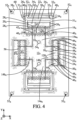
- a base 66 is arranged on the fifth layer 64, as illustrated in Figure 6 .
- This base 66 is positioned relative to the flat multilayer structure 68, in particular using the holes 54 which can receive guide pins.
- the base 66 receives a support 90 of two beams 92, connected to the support 90 by means of breakable tabs 94.
- the support 90, the beams 92 and the tongues 94 can be made in a single piece.
- the support 90, the beams 92 and the tongues 94 can be obtained by implementing the same processes as those previously described for the production of the different layers described above. It should also be noted that in the example described the support 90 is placed on the base 66, without being fixed there.
- the manufacturing process then continues with a step of deployment along a Z axis substantially normal to the plane of the flat multilayer structure 68, this step being illustrated in figures 8 to 10 .
- the multilayer structure 68 of the Figure 7 is deployed to extend it in the Z direction normal to the plane of the planar multilayer structure 68.
- FIG 8 illustrates an intermediate state of the multilayer structure 68, before reaching its final, deployed state, illustrated in Figure 10 .
- joints - that is to say, connections essentially allowing rotation - are formed at the level of the facing grooved edges.
- FIG. 9 illustrates, by way of example, the formation of a joint 72 at the level of the third and fourth edges 20, 24 of a longitudinal branch 14a of the cross 12 and the strip 22 of material facing each other.
- the grooves of the third and fourth edges 20, 24 of the third, fourth and fifth layers 58, 60, 64 are bring together, the teeth of one groove being received between two neighboring teeth of the other groove.
- the third and fourth edges 20, 24 of the first layer 10 move away.
- the second layer 56 devoid of grooved edges, remains in one piece and extends, continuously, between the base of the longitudinal branch 14a (on the right on the Figure 9 ) and the extremal portion 120 of the longitudinal branch 14a (on the left on the Figure 9 ).
- the second layer 56 then forms a joint 72.
- This Sarrus assembly is a particular example of a mounting scaffold that can be used in the process.
- Such mounting scaffolding is produced by the multilayer structure, in addition to the structure of interest that we seek to achieve.
- This assembly scaffolding makes it possible to connect the different movements necessary for the deployment of the multi-layer structure, so that this deployment can be carried out by acting on the multilayer structure according to a single degree of freedom. This assembly scaffolding thus facilitates the deployment stage.
- the assembly of Sarrus 86 thus produced thus makes it possible, by pulling on a part of the multilayer structure 68 in the direction Z, to cause a straightening of the stirrups 26.
- the straightening of the stirrups 26 is accompanied by a rimpedement of the blades 62 of the support 66.
- the straightening of the stirrups 26 also causes a pivoting of the blades 62, so that their width extends in a direction normal to the plane of the flat multilayer structure 68, the length and thickness of the blades extending substantially in a plane parallel to the plane of the multilayer structure 68, flat.
- a step of blocking the multilayer structure in its deployed configuration 88 can be implemented. This step can be done in many ways. For example, here, we can block some or all of the joints mentioned above by brazing or bonding.
- the pallets 36 fixed to the ends of the blades 62 can be fixed to masses 92, here produced in the form of beams. This can in particular be achieved by brazing. In this case, a metal plate can be glued to each end of the masses 92, thus allowing fixing by brazing.
- FIG. 11 illustrates the detachment of the assembly formed by the masses 92 secured to the blades 62 via the blades 36, from the rest of the deployed multilayer structure 88. This is achieved by cutting the tongues 34 connecting the blades 36 and the blade 62 to the stirrups 26, as well as the tabs 94 connecting the masses 92 to the support 90.
- FIG 12 illustrates the flexible mechanism 100 finally obtained.
- This flexible mechanism essentially comprises the two masses 92, the two flexible blades 62 connecting the masses 92, and the pucks 36 connecting the ends of the blades 62 to the masses 92.
- the blades 62 are more flexible than the masses 92 and the pucks 36.
- the blades 62 are made of a more flexible material than the masses 92 and, possibly, the pucks 36.
- the flexible mechanism 100 can thus form an oscillator.
- the blades 62 are oriented in such a way that they allow the flexible mechanism 100 to oscillate in a plane extending substantially in the directions X and Y.
- the blades 62 were oriented in such a way that they tended to oscillate in a plane normal to this plane.
- the blades 62 are for example one of silicon, glass, sapphire or alumina, diamond, in particular synthetic diamond, in particular synthetic diamond obtained by chemical vapor deposition process, titanium, an alloy titanium, in particular an alloy from the Gum metal ® family and an alloy from the elinvar family, in particular Elinvar ® , Nivarox ® , Thermelast ® , NI-Span-C ® and Précision C ® .
- Gum metal ® are materials comprising: 23% niobium; 0.7% tantalum; 2% zirconium; 1% oxygen; optionally vanadium; and optionally hafnium.
- Elinvar alloys are nickel steel alloys comprising nickel and chromium which are very insensitive to temperatures.
- Elinvar ® in particular, is a nickel steel alloy, comprising 59% iron, 36% nickel and 5% chromium.
- NI-Span-C ® includes between 41.0 and 43.5% nickel and cobalt; between 4.9 and 5.75% chromium; between 2.20 and 2.75% titanium; between 0.30 and 0.80% aluminum; at most 0.06% carbon; at most 0.80% manganese; at most 1% silicon; at most 0.04% sulfur; at most 0.04% phosphorus; and the 100% iron supplement.
- Précision C ® includes: 42% nickel; 5.3% chromium; 2.4% titanium; 0.55% aluminum; 0.50% silicon; 0.40% manganese; 0.02% carbon; and the 100% iron supplement.
- Nivarox ® includes: between 30 and 40% nickel; between 0.7 and 1.0% beryllium; between 6 and 9% molybdenum and/or 8% chromium; optionally, 1% titanium; between 0.7 and 0.8% manganese; between 0.1 and 0.2% silicon; carbon, up to 0.2%; and iron supplement.
- Thermelast ® includes: 42.5% nickel; less than 1% silicon; 5.3% chromium; less than 1% aluminum; less than 1% manganese; 2.5% titanium; and 48% iron.
- the blade(s) advantageously have a thickness greater than or equal to 1 ⁇ m, preferably greater than or equal to 5 ⁇ m, and/or less than or equal to 30 ⁇ m, preferably less than or equal to 20 ⁇ m, preferably less than or equal to 15 ⁇ m.
- the blade(s) may also have a width greater than or equal to 0.1 mm and/or less than or equal to 2 mm, preferably less than or equal to 1 mm.
- the blade(s) may also have a length of, for example, between 5 and 13 mm.
- the or each blade 62 can also have an aspect ratio defined as the ratio between the width and the thickness of the blade, greater than 10, preferably greater than 25.
- the masses 92 are for example one of tungsten, molybdenum, gold, silver, tantalum, platinum, alloys comprising these elements and a polymer material loaded with particles of density greater than ten, in particular tungsten particles. These materials are indeed heavy. In the case of a mechanism 100 forming an oscillator, this makes it possible to have masses 92 of reduced dimensions but with a relatively large weight.
- the pucks 36, and therefore the first, third and fifth layers 10, 58, 64 are for example made of polymer materials. These pucks 36 can improve the resistance of the mechanism 100 to shocks.
- the mechanism 100 can advantageously form an oscillator.
- one of the masses 92 can form a frame or be rigidly fixed to a frame, relative to which the other mass 92 oscillates.
- one of the masses 92 oscillates according to a circular translation movement T relative to the other mass 92.
- a high aspect ratio of the or each blade 62 makes it possible in particular to limit the oscillation modes of this or these blades 62 out of plane.
- the or each blade 62 has a free length L greater than or equal to a third of the width of the blade 62.
- the free length is defined as being the length of the blade which is not in contact with the mass.
- the free length means the length of the blade between the two masses, which is not in contact with one or the other of the masses.
- the latter is not in contact with any other element of the mechanism integrating the blade(s) 62.
- a flexible mechanism of the type of the Figure 12 that is to say of the type comprising at least one flexible blade between at least one, preferably between two masses, obtained by implementing the method previously described, is implemented in a watch movement in a part of watchmaking, for the manufacture of an oscillator, in particular as a regulator of such a watch movement.
- the masses are fixed on the blades, more precisely at the ends of the blades, after the deployment of the multilayer structure.
- this fixing is carried out using brazing.
- the masses are fixed to the blade(s), in particular at the ends of these blades, by overmolding, clamping, clipping, gluing, welding, in particular spot welding, in particular laser spot welding, or any other process accessible to those skilled in the art.
- the masses can be reported on the deployed multilayer structure, in the form of a cutout in an additional layer of material which is superimposed on the deployed multilayer structure.
- the cutting in the layer of additional material can in particular form housings for receiving the ends of the flexible blades, in particular the pucks fixed to the ends of the blades, the reception then being, preferably, carried out with clamping.
- the masses can be formed by the multilayer structure.
- the masses are then arranged opposite the ends of the blades or pallets fixed at these ends at the time of deployment of the multilayer structure.
- this step includes a step of blocking the structure in the deployed position.
- This step is a priori optional. It is however preferred when other manipulations of the structure in the deployed position are desired to achieve the mechanism. In the case where such blocking is to be carried out, this can be obtained by any means accessible to those skilled in the art, in particular by bonding, overmolding, soldering, clipping, welding, in particular spot welding, in particular welding by laser point or, more generally, by fixing together elements of the structure in the deployed position.
- the method of manufacturing a mechanism may include a step of assembling numerous layers on top of each other. Preferably, however, the number of superimposed layers of material is between ten and fifty.
- a single mechanism 100 is obtained by implementing the method.
- the same stack of layers allows the formation of a plurality of multilayer structures and/or a plurality of deployed structures. It is thus possible to significantly improve the efficiency of the process for manufacturing a mechanism.
- the grooved edges mentioned in the example described can be replaced by folding tips.
- the beginnings of folding can be made by partial cutting of the layers. Partial cuts may consist of dotted cuts and/or cutting only part of the thickness of the layers. In the case of cutting only part of the thickness of the layers, the partial cutting can possibly be continuous. Complete cutting of the layers can also be considered.
Landscapes
- Physics & Mathematics (AREA)
- General Physics & Mathematics (AREA)
- Micromachines (AREA)
Claims (15)
- Verfahren zur Herstellung eines Uhrenoszillators (100) aufweisend die Schritte, die bestehen aus:i) Verbinden von ebenen Schichten (10; 56; 58; 60; 64) miteinander, um eine im Wesentlichen ebene Mehrschichtstruktur (68) zu bilden;ii) Entfalten der Mehrschichtstruktur in eine Richtung (Z), die im Wesentlichen orthogonal zu den ebenen Schichten (10; 56; 58; 60; 64) ist;in welchem Verfahren mindestens eine erste Schicht (60) der Schichten (10; 56; 58; 60; 64) mindestens ein biegsames Blättchen (62) in dem Uhrenoszillator (100) bildet, wobei das oder die Blättchen (62) in dem Uhrenoszillator (100) an mindestens einer Masse (92), vorzugsweise an zwei Massen (92), befestigt sind, wobei die oder jede Masse (92) steifer als das oder die Blättchen (62) ist, wobei das oder die Blättchen (62) in einem Schritt nach dem Schritt ii) an der oder jeder Masse (92) befestigt werden.
- Verfahren nach Anspruch 1, in welchem jedes Blättchen (62) in dem Uhrenoszillator (100) eine freie Länge (L) aufweist, die mehr als ein Drittel der Breite des betreffenden Blättchens (62) ist, wobei die freie Länge (L) wie folgt definiert ist:- die Länge des Blättchens (62), die nicht in Kontakt mit der Masse (92) ist, in dem Fall, in dem das Blättchen (62) an einer Masse (92) befestigt ist, oder- die Länge des Blättchens (62), die sich zwischen den zwei Massen (92) erstreckt, ohne in Kontakt mit einer der Massen (92) zu sein, in dem Fall, in dem das Blättchens (62) an zwei Massen (92) befestigt ist,wobei das oder jedes Blättchen (62) über die freie Länge (L) vorzugsweise nicht in Kontakt mit einem anderen Element des Uhrenoszillators (100) ist.
- Verfahren nach Anspruch 1 oder 2, aufweisend nach dem Schritt ii) einen Schritt iii), der darin besteht, die Mehrschichtstruktur in der Entfaltungsposition (88) zu verriegeln, vorzugsweise in welchem in Schritt iii) die Struktur in der Entfaltungsposition (88) dadurch verriegelt wird, dass eine Überspritzung und/oder eine Lötung und/oder eine Klammerung und/oder eine Klebung und/oder eine Schweißung insbesondere eine Punktschweißung, speziell eine Punktschweißung mittels Laser, und/oder eine Einspannung mindestens eines Teils des Uhrenoszillators, insbesondere mindestens eines Gelenks des Uhrenoszillators, durchgeführt wird.
- Verfahren nach einem der vorstehenden Ansprüche, in welchem die oder jede Masse (92) an ein Ende, vorzugsweise ein jeweiliges Ende, eines des mindestens einen Blättchens angefügt wird.
- Verfahren nach einem der vorstehenden Ansprüche, in welchem die oder jede Masse (92) an dem Blättchen (62) oder an jedem Blättchen (62) befestigt wird durch:- Überspritzung;- Lötung;- Klammerung;- Klebung;- Schweißung, insbesondere Punktschweißung, speziell Punktschweißung mittels Laser;- Einspannung.
- Verfahren nach einem der vorstehenden Ansprüche, in welchem die Masse oder die Massen (92) aus mindestens einer der in Schritt i) verbundenen ebenen Schichten (10; 56; 58; 60; 64) realisiert werden.
- Verfahren nach einem der vorstehenden Ansprüche, in welchem die Masse oder die Massen (92) aus einem der folgenden Materialen bestehen: Wolfram, Molybdän, Gold, Silber, Tantal, Platin, Legierungen, die diese Elemente und ein Polymermaterial aufweisen, das mit Partikeln einer Dichte von mehr zehn beladen ist, insbesondere mit Wolframpartikeln.
- Verfahren nach einem der vorstehenden Ansprüche, in welchem das oder die Blättchen (62) aus einem der folgenden Materialen bestehen: Silizium, Glas, Saphir, Diamant insbesondere synthetischer Diamant, speziell durch ein Verfahren einer chemischen Abscheidung aus der Dampfphase gewonnener synthetischer Diamant, Titan, eine Titanlegierung, insbesondere eine Legierung der Gum metal ® Familie und eine Legierung der Elinvar-Familie, speziell Elinvar ®, Nivarox ®, Thermelast ®, Ni-Span-C ®, Precision C ®.
- Verfahren nach einem der vorstehenden Ansprüche, in welchem:- in Schritt i) zwischen zehn und fünfzig ebene Schichten (10; 56; 58; 60; 64) miteinander verbunden werden; und/oder- das oder die Blättchen (62) eine Breite, eine Dicke und ein Seitenverhältnis haben, das als ein Verhältnis der Breite des Blättchens (62) zur Dicke des Blättchens (62) definiert ist, wobei das Seitenverhältnis jedes Blättchens größer als 10, vorzugsweise größer als 25, ist; und/oder- das oder die Blättchen (62) eine Dicke haben, die größer oder gleich 1µm, bevorzugt größer als 5µm und/oder kleiner oder gleich 30µm, bevorzugt kleiner oder gleich 20µm, stärker bevorzugt kleiner oder gleich 15µm ist,- das oder die Blättchen (62) eine Breite haben, die größer oder gleich 0,1mm und/oder kleiner oder gleich 2mm, bevorzugt kleiner oder gleich 1mm ist.
- Verfahren nach einem der vorstehenden Ansprüche, in welchem die im Wesentlichen ebene Mehrschichtstruktur (68) mindestens ein Montagegerüst (86) bildet, wobei das Verfahren vorzugsweise nach dem Schritt iii), falls gegeben, einen Schritt iv) aufweist, der darin besteht, die Struktur in der Entfaltungsposition (88) von dem mindestens einen Montagegerüst (86) abzunehmen.
- Verfahren nach einem der vorstehenden Ansprüche, in welchem jede Schicht (10; 56; 58; 60; 64) vorzugsweise vor ihrem Verbinden einem Bearbeitungsschritt, insbesondere Laserschneiden, chemische Bearbeitung, Stanzen, Fräsen, Draht-Elektroerosion und/oder einem Formgebungsschritt, insbesondere einem Formgebungsschritt durch Materialzugabe, speziell einem Formgebungsschritt durch LIGA oder Spritzgießen, unterzogen wird.
- Verfahren nach einem der vorstehenden Ansprüche, in welchem in Schritt ii) bzw. in Schritt iii) ausgehend von einem einzigen Verbund von Schichten in Schritt i) mehrere im Wesentlichen ebene Mehrschichtstrukturen (68) bzw. Strukturen in Entfaltungsposition (88) gewonnen werden.
- Verfahren nach einem der vorstehenden Ansprüche, in welchem das oder jedes Blättchen (62) aus einem Material besteht, das weicher als die oder jede Masse (92) ist, die an dem Blättchen (62) befestigt wird.
- Uhrenoszillator, der zumindest teilweise durch Durchführen eines Verfahrens nach einem der Ansprüche 1 bis 13 hergestellt ist.
- Uhrwerk (203) für ein Uhrenteil (200) aufweisend einen Uhrenoszillator nach Anspruch 14.
Applications Claiming Priority (2)
| Application Number | Priority Date | Filing Date | Title |
|---|---|---|---|
| FR1753603A FR3065542B1 (fr) | 2017-04-25 | 2017-04-25 | Procede de fabrication d'un mecanisme |
| PCT/EP2018/060505 WO2018197516A1 (fr) | 2017-04-25 | 2018-04-24 | Procédé de fabrication d'un mécanisme |
Publications (2)
| Publication Number | Publication Date |
|---|---|
| EP3615470A1 EP3615470A1 (de) | 2020-03-04 |
| EP3615470B1 true EP3615470B1 (de) | 2024-04-24 |
Family
ID=59031227
Family Applications (1)
| Application Number | Title | Priority Date | Filing Date |
|---|---|---|---|
| EP18717965.0A Active EP3615470B1 (de) | 2017-04-25 | 2018-04-24 | Verfahren zur herstellung eines uhrenoszillators |
Country Status (6)
| Country | Link |
|---|---|
| US (1) | US11467542B2 (de) |
| EP (1) | EP3615470B1 (de) |
| JP (1) | JP7184800B2 (de) |
| CN (1) | CN111278765B (de) |
| FR (1) | FR3065542B1 (de) |
| WO (1) | WO2018197516A1 (de) |
Families Citing this family (1)
| Publication number | Priority date | Publication date | Assignee | Title |
|---|---|---|---|---|
| FR3094803B1 (fr) | 2019-04-05 | 2021-04-23 | Lvmh Swiss Mft Sa | Oscillateur sphérique pour mécanisme horloger |
Family Cites Families (12)
| Publication number | Priority date | Publication date | Assignee | Title |
|---|---|---|---|---|
| US3763544A (en) * | 1972-04-17 | 1973-10-09 | Gen Electric | Method of manufacturing type fingers |
| CN1170211C (zh) * | 1998-07-03 | 2004-10-06 | 时至准钟表股份有限公司 | 模拟式电子时钟用指针的制造方法 |
| EP1921517B1 (de) * | 2006-11-09 | 2010-05-12 | ETA SA Manufacture Horlogère Suisse | Montageelement, das dehnbare Strukturen in Form von Gabeln umfasst, und dieses Element umfassende Uhr |
| DE602006014554D1 (de) * | 2006-11-09 | 2010-07-08 | Eta Sa Mft Horlogere Suisse | Montageelement, das dehnbare Strukturen in Form von aufeinander liegenden Plättchen umfasst, und mit diesem Element ausgerüstete Uhr |
| EP1921516B1 (de) * | 2006-11-09 | 2010-01-13 | ETA SA Manufacture Horlogère Suisse | Montageelement, das zwei Reihen von dehnbaren Strukturen umfasst, und dieses Element umfassende Uhr |
| EP2105806B1 (de) * | 2008-03-27 | 2013-11-13 | Sowind S.A. | Hemmungsmechanismus |
| EP2400353A1 (de) * | 2010-06-22 | 2011-12-28 | The Swatch Group Research and Development Ltd. | Uhrenzeiger |
| WO2012109559A1 (en) | 2011-02-11 | 2012-08-16 | President And Fellows Of Harvard College | Monolithic fabrication of three-dimensional structures |
| JP5918438B2 (ja) * | 2012-03-29 | 2016-05-18 | ニヴァロックス−ファー ソシエテ アノニム | 可動フレームを備えた可撓性エスケープ機構 |
| US10376326B2 (en) * | 2013-08-04 | 2019-08-13 | President And Fellows Of Harvard College | Pop-up laminate structures with integrated electronics |
| EP3032351A1 (de) | 2014-12-09 | 2016-06-15 | LVMH Swiss Manufactures SA | Uhrmechanismus, Uhrwerk und Uhr mit solch einem Mechanismus |
| WO2016091951A1 (en) * | 2014-12-09 | 2016-06-16 | Lvmh Swiss Manufactures Sa | Mechanism for a timepiece and timepiece having such a mechanism |
-
2017
- 2017-04-25 FR FR1753603A patent/FR3065542B1/fr active Active
-
2018
- 2018-04-24 WO PCT/EP2018/060505 patent/WO2018197516A1/fr unknown
- 2018-04-24 CN CN201880042373.1A patent/CN111278765B/zh active Active
- 2018-04-24 JP JP2019557768A patent/JP7184800B2/ja active Active
- 2018-04-24 EP EP18717965.0A patent/EP3615470B1/de active Active
- 2018-04-24 US US16/608,319 patent/US11467542B2/en active Active
Also Published As
| Publication number | Publication date |
|---|---|
| FR3065542A1 (fr) | 2018-10-26 |
| JP2020517949A (ja) | 2020-06-18 |
| CN111278765B (zh) | 2024-06-11 |
| US11467542B2 (en) | 2022-10-11 |
| US20200192299A1 (en) | 2020-06-18 |
| WO2018197516A1 (fr) | 2018-11-01 |
| FR3065542B1 (fr) | 2019-07-12 |
| CN111278765A (zh) | 2020-06-12 |
| EP3615470A1 (de) | 2020-03-04 |
| JP7184800B2 (ja) | 2022-12-06 |
Similar Documents
| Publication | Publication Date | Title |
|---|---|---|
| EP2196868B1 (de) | Spirale mit Kurvenerhöhung aus Material auf Siliziumbasis | |
| EP2104006B1 (de) | Monoblock-Doppelspirale und ihr Herstellungsverfahren | |
| EP2407831B1 (de) | Spirale für Unruh-Oszillator einer Uhr, und ihr Herstellungsverfahren | |
| EP2105807B1 (de) | Monoblockspirale zur Erhöhung der Kurve und ihr Herstellungsverfahren | |
| EP2485095B1 (de) | Unruh von Kompositmaterialen | |
| EP2145237B1 (de) | Uhrenkomponente und verfahren zu ihrer herstellung | |
| EP2656151B1 (de) | Montage einer komponente ohne kunststoffbereich | |
| CH699882A2 (fr) | Spiral à élévation de courbe en matériau micro-usinable. | |
| EP2952971B1 (de) | Anker für Hemmungsmechanismus eines Uhrwerks | |
| CH700640A1 (fr) | Piece d'horlogerie allegee et renforcee. | |
| EP3502784A1 (de) | Uhrresonator mit flexibler führung | |
| EP3561607A1 (de) | Stossdämpfungsschutz eines resonatormechanismus mit flexibler drehführung | |
| EP2743781A1 (de) | Montagevorrichtung zum Verriegeln eines Verbundsystems | |
| EP3615470B1 (de) | Verfahren zur herstellung eines uhrenoszillators | |
| EP3037893B1 (de) | Mikromechanische Komponente oder Uhr mit flexiblem Führungsdraht | |
| EP3042250B1 (de) | Triebfeder einer uhr mit spielnachstellung | |
| EP3786720B1 (de) | Uhrkomponente zur aufnahme eines organs durch einpressen | |
| CH708553B1 (fr) | Mobile horloger à rattrapage de jeu. | |
| EP3432082B1 (de) | Regulierorgan | |
| EP3948433B1 (de) | Sphärischer oszillator für ein uhrwerk | |
| EP3391154B1 (de) | Schwingsystem für eine uhr | |
| WO2024175797A1 (fr) | Assemblage horloger et procédé de fabrication d'un assemblage horloger | |
| EP4191346B1 (de) | Stossdämpfungsschutz eines resonatormechanismus mit flexibler drehführung | |
| CH715889A2 (fr) | Oscillateur à lame flexible pour mécanisme de pièce d'horlogerie. | |
| EP4332686A1 (de) | Spiralfeder für eine spiralunruh-einheit einer uhrwerke |
Legal Events
| Date | Code | Title | Description |
|---|---|---|---|
| STAA | Information on the status of an ep patent application or granted ep patent |
Free format text: STATUS: UNKNOWN |
|
| STAA | Information on the status of an ep patent application or granted ep patent |
Free format text: STATUS: THE INTERNATIONAL PUBLICATION HAS BEEN MADE |
|
| PUAI | Public reference made under article 153(3) epc to a published international application that has entered the european phase |
Free format text: ORIGINAL CODE: 0009012 |
|
| STAA | Information on the status of an ep patent application or granted ep patent |
Free format text: STATUS: REQUEST FOR EXAMINATION WAS MADE |
|
| 17P | Request for examination filed |
Effective date: 20191025 |
|
| AK | Designated contracting states |
Kind code of ref document: A1 Designated state(s): AL AT BE BG CH CY CZ DE DK EE ES FI FR GB GR HR HU IE IS IT LI LT LU LV MC MK MT NL NO PL PT RO RS SE SI SK SM TR |
|
| AX | Request for extension of the european patent |
Extension state: BA ME |
|
| DAV | Request for validation of the european patent (deleted) | ||
| DAX | Request for extension of the european patent (deleted) | ||
| STAA | Information on the status of an ep patent application or granted ep patent |
Free format text: STATUS: EXAMINATION IS IN PROGRESS |
|
| 17Q | First examination report despatched |
Effective date: 20211025 |
|
| GRAP | Despatch of communication of intention to grant a patent |
Free format text: ORIGINAL CODE: EPIDOSNIGR1 |
|
| STAA | Information on the status of an ep patent application or granted ep patent |
Free format text: STATUS: GRANT OF PATENT IS INTENDED |
|
| INTG | Intention to grant announced |
Effective date: 20231115 |
|
| GRAS | Grant fee paid |
Free format text: ORIGINAL CODE: EPIDOSNIGR3 |
|
| GRAA | (expected) grant |
Free format text: ORIGINAL CODE: 0009210 |
|
| STAA | Information on the status of an ep patent application or granted ep patent |
Free format text: STATUS: THE PATENT HAS BEEN GRANTED |
|
| AK | Designated contracting states |
Kind code of ref document: B1 Designated state(s): AL AT BE BG CH CY CZ DE DK EE ES FI FR GB GR HR HU IE IS IT LI LT LU LV MC MK MT NL NO PL PT RO RS SE SI SK SM TR |
|
| REG | Reference to a national code |
Ref country code: GB Ref legal event code: FG4D Free format text: NOT ENGLISH |
|
| REG | Reference to a national code |
Ref country code: CH Ref legal event code: EP |
|
| REG | Reference to a national code |
Ref country code: DE Ref legal event code: R096 Ref document number: 602018068506 Country of ref document: DE |
|
| REG | Reference to a national code |
Ref country code: IE Ref legal event code: FG4D Free format text: LANGUAGE OF EP DOCUMENT: FRENCH |
|
| REG | Reference to a national code |
Ref country code: LT Ref legal event code: MG9D |
|
| REG | Reference to a national code |
Ref country code: NL Ref legal event code: FP |
|
| REG | Reference to a national code |
Ref country code: AT Ref legal event code: MK05 Ref document number: 1679437 Country of ref document: AT Kind code of ref document: T Effective date: 20240424 |
|
| PG25 | Lapsed in a contracting state [announced via postgrant information from national office to epo] |
Ref country code: IS Free format text: LAPSE BECAUSE OF FAILURE TO SUBMIT A TRANSLATION OF THE DESCRIPTION OR TO PAY THE FEE WITHIN THE PRESCRIBED TIME-LIMIT Effective date: 20240824 |
|
| PG25 | Lapsed in a contracting state [announced via postgrant information from national office to epo] |
Ref country code: BG Free format text: LAPSE BECAUSE OF FAILURE TO SUBMIT A TRANSLATION OF THE DESCRIPTION OR TO PAY THE FEE WITHIN THE PRESCRIBED TIME-LIMIT Effective date: 20240424 |
|
| PG25 | Lapsed in a contracting state [announced via postgrant information from national office to epo] |
Ref country code: HR Free format text: LAPSE BECAUSE OF FAILURE TO SUBMIT A TRANSLATION OF THE DESCRIPTION OR TO PAY THE FEE WITHIN THE PRESCRIBED TIME-LIMIT Effective date: 20240424 Ref country code: FI Free format text: LAPSE BECAUSE OF FAILURE TO SUBMIT A TRANSLATION OF THE DESCRIPTION OR TO PAY THE FEE WITHIN THE PRESCRIBED TIME-LIMIT Effective date: 20240424 |
|
| PG25 | Lapsed in a contracting state [announced via postgrant information from national office to epo] |
Ref country code: GR Free format text: LAPSE BECAUSE OF FAILURE TO SUBMIT A TRANSLATION OF THE DESCRIPTION OR TO PAY THE FEE WITHIN THE PRESCRIBED TIME-LIMIT Effective date: 20240725 |
|
| PG25 | Lapsed in a contracting state [announced via postgrant information from national office to epo] |
Ref country code: PT Free format text: LAPSE BECAUSE OF FAILURE TO SUBMIT A TRANSLATION OF THE DESCRIPTION OR TO PAY THE FEE WITHIN THE PRESCRIBED TIME-LIMIT Effective date: 20240826 |
|
| PGFP | Annual fee paid to national office [announced via postgrant information from national office to epo] |
Ref country code: FR Payment date: 20240827 Year of fee payment: 7 |