EP3612792B1 - Verfahren und system zum erfassen einer eigenschaft eines einer betriebsmaschine zugeführten textil- oder metallfadens - Google Patents
Verfahren und system zum erfassen einer eigenschaft eines einer betriebsmaschine zugeführten textil- oder metallfadens Download PDFInfo
- Publication number
- EP3612792B1 EP3612792B1 EP18717710.0A EP18717710A EP3612792B1 EP 3612792 B1 EP3612792 B1 EP 3612792B1 EP 18717710 A EP18717710 A EP 18717710A EP 3612792 B1 EP3612792 B1 EP 3612792B1
- Authority
- EP
- European Patent Office
- Prior art keywords
- characteristic
- thread
- detection
- operating
- analog
- Prior art date
- Legal status (The legal status is an assumption and is not a legal conclusion. Google has not performed a legal analysis and makes no representation as to the accuracy of the status listed.)
- Active
Links
- 238000000034 method Methods 0.000 title claims description 32
- 239000004753 textile Substances 0.000 title claims description 16
- 239000002184 metal Substances 0.000 title description 9
- 238000001514 detection method Methods 0.000 claims description 57
- 238000012544 monitoring process Methods 0.000 claims description 33
- 230000003287 optical effect Effects 0.000 claims description 23
- 238000005286 illumination Methods 0.000 claims description 12
- 206010020112 Hirsutism Diseases 0.000 claims description 5
- 238000012545 processing Methods 0.000 claims description 4
- 230000006870 function Effects 0.000 claims description 3
- 238000012986 modification Methods 0.000 claims 1
- 230000004048 modification Effects 0.000 claims 1
- 238000005259 measurement Methods 0.000 description 37
- 239000000047 product Substances 0.000 description 11
- 230000007547 defect Effects 0.000 description 6
- 238000005070 sampling Methods 0.000 description 5
- 238000011156 evaluation Methods 0.000 description 4
- 239000000463 material Substances 0.000 description 4
- 238000004804 winding Methods 0.000 description 4
- 238000004458 analytical method Methods 0.000 description 3
- 230000000694 effects Effects 0.000 description 3
- 239000000835 fiber Substances 0.000 description 3
- 238000005305 interferometry Methods 0.000 description 3
- 239000004065 semiconductor Substances 0.000 description 3
- 238000013459 approach Methods 0.000 description 2
- 230000008901 benefit Effects 0.000 description 2
- 230000008859 change Effects 0.000 description 2
- 239000007795 chemical reaction product Substances 0.000 description 2
- 238000005516 engineering process Methods 0.000 description 2
- 210000004209 hair Anatomy 0.000 description 2
- 238000009940 knitting Methods 0.000 description 2
- 230000008569 process Effects 0.000 description 2
- 230000001133 acceleration Effects 0.000 description 1
- 230000002411 adverse Effects 0.000 description 1
- 238000004364 calculation method Methods 0.000 description 1
- 238000006243 chemical reaction Methods 0.000 description 1
- 230000001427 coherent effect Effects 0.000 description 1
- 238000001816 cooling Methods 0.000 description 1
- 238000005314 correlation function Methods 0.000 description 1
- 238000001914 filtration Methods 0.000 description 1
- 238000004519 manufacturing process Methods 0.000 description 1
- 239000011159 matrix material Substances 0.000 description 1
- 239000013307 optical fiber Substances 0.000 description 1
- 230000005855 radiation Effects 0.000 description 1
- 230000004044 response Effects 0.000 description 1
- 230000008719 thickening Effects 0.000 description 1
Images

Classifications
-
- B—PERFORMING OPERATIONS; TRANSPORTING
- B65—CONVEYING; PACKING; STORING; HANDLING THIN OR FILAMENTARY MATERIAL
- B65H—HANDLING THIN OR FILAMENTARY MATERIAL, e.g. SHEETS, WEBS, CABLES
- B65H61/00—Applications of devices for metering predetermined lengths of running material
- B65H61/005—Applications of devices for metering predetermined lengths of running material for measuring speed of running yarns
-
- G—PHYSICS
- G01—MEASURING; TESTING
- G01B—MEASURING LENGTH, THICKNESS OR SIMILAR LINEAR DIMENSIONS; MEASURING ANGLES; MEASURING AREAS; MEASURING IRREGULARITIES OF SURFACES OR CONTOURS
- G01B11/00—Measuring arrangements characterised by the use of optical techniques
- G01B11/08—Measuring arrangements characterised by the use of optical techniques for measuring diameters
- G01B11/10—Measuring arrangements characterised by the use of optical techniques for measuring diameters of objects while moving
- G01B11/105—Measuring arrangements characterised by the use of optical techniques for measuring diameters of objects while moving using photoelectric detection means
-
- B—PERFORMING OPERATIONS; TRANSPORTING
- B65—CONVEYING; PACKING; STORING; HANDLING THIN OR FILAMENTARY MATERIAL
- B65H—HANDLING THIN OR FILAMENTARY MATERIAL, e.g. SHEETS, WEBS, CABLES
- B65H63/00—Warning or safety devices, e.g. automatic fault detectors, stop-motions ; Quality control of the package
- B65H63/06—Warning or safety devices, e.g. automatic fault detectors, stop-motions ; Quality control of the package responsive to presence of irregularities in running material, e.g. for severing the material at irregularities ; Control of the correct working of the yarn cleaner
- B65H63/062—Electronic slub detector
- B65H63/065—Electronic slub detector using photo-electric sensing means, i.e. the defect signal is a variation of light energy
-
- D—TEXTILES; PAPER
- D01—NATURAL OR MAN-MADE THREADS OR FIBRES; SPINNING
- D01H—SPINNING OR TWISTING
- D01H13/00—Other common constructional features, details or accessories
- D01H13/26—Arrangements facilitating the inspection or testing of yarns or the like in connection with spinning or twisting
-
- D—TEXTILES; PAPER
- D01—NATURAL OR MAN-MADE THREADS OR FIBRES; SPINNING
- D01H—SPINNING OR TWISTING
- D01H13/00—Other common constructional features, details or accessories
- D01H13/32—Counting, measuring, recording or registering devices
-
- G—PHYSICS
- G01—MEASURING; TESTING
- G01B—MEASURING LENGTH, THICKNESS OR SIMILAR LINEAR DIMENSIONS; MEASURING ANGLES; MEASURING AREAS; MEASURING IRREGULARITIES OF SURFACES OR CONTOURS
- G01B11/00—Measuring arrangements characterised by the use of optical techniques
- G01B11/24—Measuring arrangements characterised by the use of optical techniques for measuring contours or curvatures
- G01B11/2433—Measuring arrangements characterised by the use of optical techniques for measuring contours or curvatures for measuring outlines by shadow casting
-
- G—PHYSICS
- G01—MEASURING; TESTING
- G01N—INVESTIGATING OR ANALYSING MATERIALS BY DETERMINING THEIR CHEMICAL OR PHYSICAL PROPERTIES
- G01N21/00—Investigating or analysing materials by the use of optical means, i.e. using sub-millimetre waves, infrared, visible or ultraviolet light
- G01N21/84—Systems specially adapted for particular applications
- G01N21/88—Investigating the presence of flaws or contamination
- G01N21/89—Investigating the presence of flaws or contamination in moving material, e.g. running paper or textiles
- G01N21/8914—Investigating the presence of flaws or contamination in moving material, e.g. running paper or textiles characterised by the material examined
- G01N21/8915—Investigating the presence of flaws or contamination in moving material, e.g. running paper or textiles characterised by the material examined non-woven textile material
-
- G—PHYSICS
- G01—MEASURING; TESTING
- G01N—INVESTIGATING OR ANALYSING MATERIALS BY DETERMINING THEIR CHEMICAL OR PHYSICAL PROPERTIES
- G01N21/00—Investigating or analysing materials by the use of optical means, i.e. using sub-millimetre waves, infrared, visible or ultraviolet light
- G01N21/84—Systems specially adapted for particular applications
- G01N21/88—Investigating the presence of flaws or contamination
- G01N21/95—Investigating the presence of flaws or contamination characterised by the material or shape of the object to be examined
- G01N21/952—Inspecting the exterior surface of cylindrical bodies or wires
-
- B—PERFORMING OPERATIONS; TRANSPORTING
- B65—CONVEYING; PACKING; STORING; HANDLING THIN OR FILAMENTARY MATERIAL
- B65H—HANDLING THIN OR FILAMENTARY MATERIAL, e.g. SHEETS, WEBS, CABLES
- B65H2701/00—Handled material; Storage means
- B65H2701/30—Handled filamentary material
- B65H2701/31—Textiles threads or artificial strands of filaments
-
- D—TEXTILES; PAPER
- D02—YARNS; MECHANICAL FINISHING OF YARNS OR ROPES; WARPING OR BEAMING
- D02H—WARPING, BEAMING OR LEASING
- D02H13/00—Details of machines of the preceding groups
-
- D—TEXTILES; PAPER
- D04—BRAIDING; LACE-MAKING; KNITTING; TRIMMINGS; NON-WOVEN FABRICS
- D04B—KNITTING
- D04B35/00—Details of, or auxiliary devices incorporated in, knitting machines, not otherwise provided for
- D04B35/10—Indicating, warning, or safety devices, e.g. stop motions
-
- G—PHYSICS
- G01—MEASURING; TESTING
- G01B—MEASURING LENGTH, THICKNESS OR SIMILAR LINEAR DIMENSIONS; MEASURING ANGLES; MEASURING AREAS; MEASURING IRREGULARITIES OF SURFACES OR CONTOURS
- G01B11/00—Measuring arrangements characterised by the use of optical techniques
- G01B11/16—Measuring arrangements characterised by the use of optical techniques for measuring the deformation in a solid, e.g. optical strain gauge
Definitions
- the present invention relates to a method for detecting a characteristic of a textile or metal thread fed to an operating machine in accordance with the precharacterising clause of independent claim 1.
- a system for detecting such a characteristic of the thread and operating in accordance with said method in accordance with the corresponding independent claim 10 also comprise the object of the present invention.
- the term "thread” is intended to mean both a textile thread or yarn and a metal thread; similarly the term “operating machine” means both a textile machine (loom, warping machine, knitting machine, interlaced winding machine, or other machine) and a machine carrying out any operation on a metal thread such as winding onto a spool.
- end product means both a textile manufacture and a product containing the monitored thread, whether textile or metal (such as a bobbin).
- characteristic of the thread is meant any of its dimensional characteristics (such as diameter or fineness or local thickening or thinning), a local surface deformation (filaments or hairs projecting from the surface of the fibre), a change in the linearity of the fibre (such as winding upon itself to form a loop), or even a characteristic associated with movement of the thread such as its rate of feed to the operating machine.
- Such sensors work on the basis of a physical principle of measurement comprising estimating the size of the shadow generated by the thread on the detector part of such a sensor after the thread has been "struck" by light emission generated from an illuminating device, such as an LED. On the basis of such estimate it is possible, for example, to determine the diameter of the thread or the presence of any surface irregularities or knots in it.
- sensors In the main there are two types of sensors that are currently alternatives to each other, that is sensors operating in analog mode or digital sensors (that is, in general they operate through detection of the analog type or digital type detection respectively).
- Analog sensors usually comprise a photodiode onto which the shadow of the thread struck by the light generated by a LED is formed. Assuming that the illumination is planar and uniform, the amount of light measured by the sensor is proportional to the ratio between the thickness or width "d" of the shadow of the thread and the width "W" of the photodiode.
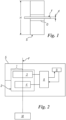
- Figure 1 shows a typical photodiode S on which a shadow O of a thread F is formed; dimensions d and W and the length or height H of the photodiode are shown in that figure.
- analog sensors do not make highly accurate determinations and their measurements depend on many factors. For example, as far as the illumination of the thread is concerned, this must be well collimated (that is neither divergent nor convergent) so that there is no variation in the magnitude of the shadow of the thread generated on the photodiode in relation to the distance between the thread and the photodiode.
- This method of estimating the diameter is simple and quick, but suffers from various accuracy problems due to the possible variability of the light source over time and lack of uniformity in space, ambient light, possible transparency of the thread, non-uniform response of the photodiode, and also errors associated with the hairiness of the thread or surface irregularities on it.
- the analog sensor is replaced by an array of sensors (typically manufactured using CMOS or CCD technology)
- the diameter of the thread can be estimated with greater accuracy using algorithms to determine the position of the edges of the shadow generated. Accuracy of measurement is guaranteed by the geometry of the sensor itself, with a resolution of the order of a few micrometres (pixel dimensions).
- GB-2064106 describes a CCD device comprising a hundred or so optical sensors, said device being designed to analyse filiform images and being capable of determining the diameter of a thread.
- the shadow generated by the thread is scanned at points along the length of the CCD, that is each of the optical sensors is examined in sequence about its condition of exposure.
- the CCD consequently produces a sequence of pulses for each scanning cycle.
- the diameter of the thread is thus continuously transformed into a large number of serial pulses.
- US-4511253 also describes a linear array of optical sensors and a circuit for evaluating the serial signals provided by said linear array.
- WO-9936746 furthermore describes a CCD sensor and a method for determining the thickness of a thread.
- WO-2011147385 unlike the previous patent documents which refer to measurement means using CCD sensors, describes the preferable use of NMOS (Live MOS), JFET, LBCSAST and Scmos sensors, because their low consumption is an advantage when they are incorporated into small devices and they do not require a cooling system.
- NMOS Live MOS
- JFET JFET
- LBCSAST Low MOS
- Scmos sensors because their low consumption is an advantage when they are incorporated into small devices and they do not require a cooling system.
- EP-1319926 describes a means intended to measure at least one property of a thread, such as for example the diameter.
- the optical sensor used is a CMOS sensor.
- EP-2827127 describes an optical sensor comprising two parallel rows of optical elements.
- the optical elements in the first row are of rectangular shape and orientated in such a way as to have their long sides along the direction of movement of the projection of the thread.
- the optical elements in the second row are also of rectangular shape but are orientated in such a way that their long side is perpendicular to the direction of movement of the projection of the thread. In this case all the optical elements are also constructed using CMOS technology.
- JP-S60114704 does not refer precisely to a thread but to a cable or the like and describes the method of measuring its diameter on the basis of the width of the shadow detected by an optical sensor, the width of the shadow being constant even if the distance between the cable and the optical sensor varies.
- the main defect of this type of sensor lies in speed of measurement.
- the number of signals which have to be acquired from an array of sensors is equal to their number of pixels.
- This may be overcome by connecting the digital sensors to (final) means for measurement of the monitored characteristic having very high calculation speeds (operating on the basis of the signals emitted by those sensors), but this would result in higher costs for the assembly or system so obtained.
- the use of digital sensors generating signals which for example also correspond to tens of thousands of measurements of the diameter of a thread per second cannot be associated with the use of low cost digital electronics or microcontrollers which would otherwise make it possible to produce a detection system of acceptable cost.
- GB 2159621 relates to a method and equipment for monitoring the dimensions of various products, both stationary and in movement.
- This prior patent text describes that a product which has to be scanned is illuminated by a laser beam and the resulting transmitted light is collected by a photocell. At the same time this product is also illuminated by another light beam in another position and the light transmitted beyond the product is collected by another photocell.
- the first photocell gives rise to a pulse signal which in the patent text is indicated as being digital, while the second photocell generates an analog signal; these signals are processed separately by (different) electronic circuits generating two versions of a measurement of the moving product.
- the two signals are summed and the result is an analog value for accurate measurement of the diameter.
- WO 00/62013 relates to a method and equipment for measuring the diameter of transparent fibres and monitoring their surface defects.
- This prior document relates to measurement of the above-mentioned characteristics of optical fibres through detecting the number of interference fringes and instead does not measure the geometrical shadow generated by the product measured on a detector.
- the known invention requires the use of coherent light which must necessarily be generated by a laser. Consequently, both because of the mode of operation (based on interferometry) and the means used to obtain such measurement and monitoring of the product, the known solution is very complex (also because it detects internal defects in the fibres or "air-lines") and is very costly. This solution therefore needs means to analyse the data obtained, which are quite complex and costly.
- US 6219135 describes a device for optically detecting at least one parameter (such as the diameter) of a moving filamentous material.
- This device comprises an optical sensor having two detector parts or individual sensors, a first individual sensor operating in analog mode and a second individual sensor operating in digital mode.
- the thread or filamentous material moves between the optical sensor and a light source, which may also be a direct source or one capable of generating light rays that are reflected before they illuminate the thread.
- the data detected by the individual sensors are processed by an evaluation circuit which generates a signal proportional to the diameter of the thread or filamentous material. Accuracy of measurement depends on the number of individual sensors used per unit length of optical sensor or whether the individual signals generated by the individual sensors are modulated (that is processed in analog mode) or only recorded in binary form (a digital signal being obtained in this way).
- EP 2423144 describes a device for detecting the movement of a thread which comprises detection of the aforesaid diameter using sensors of lack of uniformity located at a distance from each other. The values determined from two sensors are compared by similarity so as to define the degree of similarity between the data detected; these degrees of similarity are then weighed against each other.
- CH 671041 describes an electro-optical sensor device for the geometrical characteristics of the thread which uses an electro-optical sensor generating an analog signal that is digitised after filtering.
- a unit for detecting Moiré defects is provided.
- the object of this invention is to provide a method and a system implementing such method and a sensor used in such a system through which the characteristics of the textile or metal thread fed to an operating machine can be determined quickly and accurately, and achieved at low cost.
- the object of the invention is to offer a method, a system and a sensor of the type mentioned through which one or more dimensional characteristics of the thread such as its diameter, fineness, hairiness, geometrical shape and the number of twists can be detected.
- Another object is that of providing a method, a system or a sensor of the type mentioned which is capable of detecting the rate at which the thread is fed.
- Another object is to provide a system of the type mentioned above which is of small dimensions such as to facilitate its use in textile machines operating with hundreds of threads at the same time.
- a further object is that of providing a method, a system and a sensor of the type mentioned through which the characteristic of the thread can be measured directly using ambient light and without the need to use infrared radiation.
- this shows a system 1 for detecting a characteristic of a thread F fed to an operating machine M.
- This thread acts together with an optical sensor 2 which in the example in the figure has an analog detection part 3 and a digital detection part 4 associated with a single container body 5 and located at a short distance between them in such body 5.
- This makes it possible to have a detection system 1 (or detection unit or detection device) of very small dimensions such that it can be used with other identical systems for each thread monitored in textile machines operating on hundreds of threads, such as knitting machines or the like.
- Compactness of system 1 is also achieved thanks to the fact that only 1 light source or LED (not shown in Figure 2 ) capable of generating light which "impacts" on thread F and allows a shadow to be generated on both of said detection parts 3 and 4 such as to allow said parts to emit electrical signals corresponding to the dimensions of such shadow upon them is also present in body 5.
- analog detection part 3 may be a photodiode
- part 4 may be a CMOS or CCD sensor, or a similar semiconductor sensor.
- Part 4 spatially digitises the shadow of the thread created thereupon, using a vectorial sensor.
- the semiconductor sensors in part 4 define a matrix of photodetectors, through which the spatial digitalisation mentioned above is achieved.
- Detection parts 3 and 4 are connected to a monitoring or evaluation unit 8 of the microprocessor type (also present in body 5) which calculates the value of a monitored characteristic of thread F (for example, the diameter) on the basis of the electrical signals or data emitted by those parts 3 and 4.
- Unit 8 receives and analyses the signals originating from both sensor 3 and sensor 4.
- This unit 8 is connected to a memory unit 9 into which predetermined accepted values (or monitoring parameters) for the monitored characteristics are inserted, and using these unit 8 compares the data found or actual data with them in order to evaluate how they correspond to the predetermined values; if there is no uniformity between the actual value and the value in memory, unit 8 acts in a known way, for example, by producing a visible and/or audible warning, generating a signal to a device feeding thread F to machine M or other known device, to prevent a thread F having characteristics differing from those desired from continuing to be used by machine M.
- System 1 provides that the measurement made by digital part 4 of sensor 2 (which takes the form of an electrical signal) provides a real-time calibration of the measurement made in analog part 3 (which also takes the form of an electrical signal). It should be noted that the term “calibration” indicates a periodical determination of the measurement from analog part 3 of sensor 2 and comparing this measurement with the value of the diameter measured by digital part 4 of such sensor.
- the "calibrated" electrical signal originating from such parts 3 and 4 is used by unit 8 to perform the evaluation indicated above.
- the measurement of diameter made by such sensor or analog part 3 may also be expressed by a linear equation with the power measured by analog part 3.
- d H 1 ⁇ C t ⁇ P MIS
- P MIS 6 is the value of the power measured by analog part 3 (photodiode), a value which varies over time
- H is the known dimension of analog part 3
- C is a variable (which we will define as the "calibration variable") that is a function of time and depends on various factors: the illuminating optical power, any dirt present, any transparency of the thread and any variability in the gain of the electronics (thinking of background values which vary with temperature).
- the value of the variable C(t) over time is evaluated at a predetermined frequency, higher than 100-150 Hz, advantageously higher than 200 Hz, preferably at 300 Hz.
- the vibrations affecting the thread in its movement from a bobbin (from which it is unwound) to the operating machine (textile machine or machine operating on a metal thread) are of the order of at most 10 Hz.
- the image of the thread detected by analog part 3 of sensor 2 certainly shows the thread as if it were completely still and such as to allow its characteristics and in particular its diameter to be determined.
- the signal detected by part 4 is also sampled at the same frequencies, and this also makes it possible to detect the characteristics of the thread as if it were still in the case of that digital part or sensor 4.
- calibration parameter or variable C is calculated by means of a measurement of diameter d1 made by digital part 4 of sensor 2, at for example at least 100 Hz (or higher) the problematical effects mentioned can be compensated for (for the reasons mentioned above). This rate of measurement can be easily achieved with a CMOS sensor and low-cost electronics.
- the method according to the invention therefore provides that analog part 3 of sensor 2 independently detects the characteristic (for example the diameter) of the monitored thread in a manner which is in itself known and produces its own detection signal, sending it to unit 8.
- the measurement by part 3 of sensor 2 is fast but, as is known, inaccurate.
- digital part 4 of sensor 2 independently and in a manner which is in itself known also detects the above-mentioned characteristic (d1) and generates its own signal sending it to unit 8.
- the latter using the means described above, calibrates the signal from part 3 with the signal generated by digital part 4, a signal which is more accurate than that from the analog part, and is generated at a low sampling speed, as a result of which a microprocessor unit 8 (or “microcontroller”) of very small (and commercially acceptable) dimensions and costs can be used.
- unit 8 acts to compare this signal with data placed in memory and if there is any difference from the latter, it generates a warning or acts in the manners indicated above.
- FIG 3 shows a system for measuring the fineness of a thread F, which requires two measurement axes (X and Y in Figure 3 ).
- X and Y in Figure 3
- Semi-cylindrical lenses 12 which collimate the light to sensors 2 and unit 8 which is considered to include circuit 20 described above are also present in the figure.
- the LED are also connected to this unit 8.
- a system for measuring fineness needs two measurement axes, and this can be brought about by duplicating the approach described in two dimensions.
- the system may be pulsed, carrying out selective detection through both the photodiodes and the CMOS sensors.
- a sequence of three lighting states may be provided: light on the first axis, light on the second axis, dark. In this way, the measurement difference with respect to dark makes it possible to eliminate disturbances in ambient light without it being necessary to resort to optical filters, and it is therefore also possible to work with visible light.
- One example of the use of the system in figure 3 is as follows. Wishing to make a measurement at 33 kHz, it is possible to produce individual light pulses having a duration of 10 us, for an overall time of 30 us, provided by two pulses (one per axis) and 10 us of dark to measure the background luminosity. Two CMOS sensors of 512 pixels are sampled at 1 MHz, obtaining a sampling time of approximately 0.5 ms for an individual CMOS, and this becomes 1 ms for both of the sensors if acquired in sequence. 0.5 ms is sufficient for acquisition in parallel. The time for digital processing of the data to calculate measurement of the diameter has to be added to this time, and this is limited to approximately 2 ms for a low cost microcontroller.
- the measurement made by the two photodiodes at approximately 300 Hz can be calibrated, and this comprises a data flow at 33 kHz, quite sufficient to detect knots or defects.
- FIG 4 shows a system 1 which can also be used to determine the rate of feed of thread F along the X axis (or at right angles to the Y axis).
- anomalies relating to a physical characteristic of a thread are usually monitored on the basis of predetermined monitoring parameters or values such as a percentage and a length.
- the presence of a knot will be detected through a 50% increase in fineness over a 1 mm length of thread.
- a monitoring unit (such as unit 8) which checks the characteristics of the thread must operate on the basis of a suitable algorithm that is also based on knowledge of the rate at which the thread is fed so that it is possible to calculate in real time how long a detected anomaly in the thread needs to last so as to have a monitored thread length of 1 mm.
- One of the advantages of being able to calculate the speed of the thread in real time is that in this way speed is no longer included in the group of parameters that have to be programmed to monitor feed of the thread to the textile machine. Also the system succeeds in keeping the monitoring threshold independent of the speed of the machine, ensuring measurement of the length needed to evaluate the anomaly in fineness and/or the diameter of the thread even during acceleration or deceleration stages or in cases where the operator changes the process speed.
- the speed signal may also be used as a synchronisation signal to enable or disable monitoring, for example monitoring enabled at above 300 metres/minute.
- speed is determined by comparing the signals generated by a pair of analog parts 3A and 3B present in sensor 2 located on and operating along the X axis. Knowing the distance between said analog parts, and determining the delay in detection time for a particular characteristic of the thread (for example, a hair, a change in diameter or other characteristic) it is possible to determine the rate at which the thread is fed, using the known mathematical formula linking time, distance and speed.
- the most robust known technique for such determination comprises calculating the correlation function between the two analog signals, which will show a peak corresponding to the delay in detection time in the situation in which the thread has minimal surface defects.
Landscapes
- Engineering & Computer Science (AREA)
- Textile Engineering (AREA)
- Physics & Mathematics (AREA)
- General Physics & Mathematics (AREA)
- Quality & Reliability (AREA)
- Biochemistry (AREA)
- Pathology (AREA)
- Analytical Chemistry (AREA)
- Life Sciences & Earth Sciences (AREA)
- General Health & Medical Sciences (AREA)
- Health & Medical Sciences (AREA)
- Immunology (AREA)
- Chemical & Material Sciences (AREA)
- Mechanical Engineering (AREA)
- Length Measuring Devices By Optical Means (AREA)
- Investigating Materials By The Use Of Optical Means Adapted For Particular Applications (AREA)
- Spinning Or Twisting Of Yarns (AREA)
- Warping, Beaming, Or Leasing (AREA)
- Treatment Of Fiber Materials (AREA)
Claims (17)
- Verfahren zum Erfassen und Überwachen eines Merkmals, nämlich eines Durchmessers, eines Fadens (F), der einer Arbeitsmaschine (M) zugeführt wird, das Verfahren umfassend ein optisches Erfassen eines solchen überwachten Merkmals, wobei die optische Erfassung mit einer Beleuchtung des Fadens ausgeführt wird, wobei das Verfahren eine erste Erfassung des Merkmals unter Verwendung von Einrichtungen (3) eines analogen Typs und eine zweite Erfassung des Merkmals unter Verwendung von Einrichtungen (4) eines digitalen Typs bereitstellt, die zweite Erfassung des digitalen Typs eine Bestimmung eines Werts des überwachten Merkmals ermöglicht, wobei der Wert verwendet wird, um einen Wert des überwachten Merkmals zu kalibrieren, der bei der ersten Erfassung des analogen Typs erlangt wurde, um den endgültigen Wert des überwachten Merkmals genau zu identifizieren, die erste Erfassung des Merkmals eines analogen Typs und die zweite Erfassung eines solchen Merkmals (4) eines digitalen Typs unabhängig, separat ausgeführt werden und entsprechende Daten erzeugen, die an eine Überwachungseinheit (8) gesendet werden, wobei die Überwachungseinheit (8) in einer ersten Stufe den Wert des obigen Merkmals basierend auf den erfassten Daten unter Verwendung der Einrichtungen (4) eines digitalen Typs bestimmt und eine Kalibrierungsvariable C(t) basierend auf dem bestimmten digitalen Wert berechnet, wobei die Überwachungseinheit (8) in einer zweiten Stufe die Daten, die von der Einrichtung (3) eines analogen Typs erfasst werden, basierend auf der Kalibrierungsvariablen ändert, die von einem solchen Wert des Merkmals eines digitalen Typs abhängig sind, der bei der zweiten Erfassung bestimmt wird, diese Änderung in Echtzeit erfolgt und ermöglicht, die Erfassung des Merkmals eines analogen Typs zu kalibrieren, um den endgültigen Wert des überwachten Merkmals zu bestimmen, dadurch gekennzeichnet, dass die Kalibrierungsvariable C(t) über die Zeit variiert und gemäß der folgenden Formel berechnet wird
 C die Kalibrierungsvariable istd1 das Merkmal des Fadens ist, das von dem Detektorteil gemessen wird, der in digitalem Modus betrieben wirdPMIS der Wert der Leistung ist, der von dem Detektorteil gemessen wird, der in analogem Modus betrieben wirdH die Abmessung des Detektorteils ist, der in analogem Modus betrieben wird,wobei das Merkmal d, das von dem Detektorteil erfasst wird, der in analogem Modus betrieben wird, gemäß der folgenden Formel erlangt wird
- Verfahren nach Anspruch 1, dadurch gekennzeichnet, dass die Überwachungseinheit (8) einen solchen endgültigen Wert des überwachten Merkmals mit vordefinierten Werten oder Überwachungsparametern des überwachten Merkmals vergleicht, um zu prüfen, ob er mit den vorbestimmten Sollwerten übereinstimmt; wenn eine solche Übereinstimmung nicht auftritt, erzeugt die Überwachungseinheit (8) ein Warnsignal und/oder wirkt auf eine Zuführung des Fadens zu der Arbeitsmaschine ein, um zu verhindern, dass ein Faden, der ein Merkmal aufweist, das sich von dem vordefiniert eingestellten Merkmal unterscheidet, verarbeitet wird.
- Verfahren nach Anspruch 1, dadurch gekennzeichnet, dass die Kalibrierungsvariable mit einer Frequenz über 100-150 Hz, vorteilhafterweise über 200 Hz und vorzugsweise über 300 Hz von der Überwachungseinheit (8) abgetastet wird.
- Verfahren nach Anspruch 1, dadurch gekennzeichnet, dass bereitgestellt ist, dass die erste und die zweite Erfassung durch Beleuchten der Einrichtungen (4) eines digitalen Typs und der Einrichtungen eines analogen Typs mit Lichtstrahlen ausgeführt werden, die auf jeder von zwei Raumachsen (X, Y) im rechten Winkel zueinander liegen, wobei die Erfassungen mit Lichtstrahlen auf den beiden Raumachsen miteinander verglichen oder gekreuzt werden können, um eine physikalische Eigenschaft des Fadens (F) zu bestimmen.
- Verfahren nach Anspruch 1, dadurch gekennzeichnet, dass als weiteres Eigenschaft des Fadens, die erfasst und überwacht wird, alternativ ein physikalisches Merkmal des Fadens (F) oder ein Merkmal ist, das mit der Zuführung eines solchen Fadens (F) zu einer Textilmaschine assoziiert ist.
- Verfahren nach Anspruch 5, dadurch gekennzeichnet, dass das weitere physikalische Merkmal mindestens eines von der Feinheit, dem Vorhandensein lokaler Oberflächenvariationen in dem Faden (F) an sich, dem Vorhandensein von Knoten entlang des Fadens, seiner Behaarung, seiner geometrische Form oder der Anzahl an Windungen, denen der Faden unterzogen wurde, ist.
- Verfahren nach Anspruch 5, dadurch gekennzeichnet, dass das Merkmal, das mit einem Zuführen des Fadens (F) zu der Arbeitsmaschine (M) assoziiert ist, dessen Zufuhrgeschwindigkeit ist.
- Verfahren nach Anspruch 4, dadurch gekennzeichnet, dass eine Abfolge von mindestens zwei Beleuchtungsstufen des Fadens (F) bereitgestellt ist, wobei eine dieser Stufen Null-Beleuchtung oder Dunkelheit umfasst.
- Verfahren nach Anspruch 8, dadurch gekennzeichnet, dass eine Abfolge von drei Beleuchtungsstufen des Fadens (F) bereitgestellt ist, um die erste und zweite Erfassung abwechselnd auf einer der Achsen (X, Y) zu erhalten, wobei eine dieser Stufen Dunkelheit umfasst.
- System zum Erfassen und Überwachen eines Merkmals, nämlich eines Durchmessers, eines Fadens (F), der einer Arbeitsmaschine (M) zugeführt wird, das System umfassend eine Überwachungseinheit (8), die zum Implementieren des in Anspruch 1 genannten Verfahrens konfiguriert ist, das System umfassend Detektionseinrichtungen (2) eines optischen Typs für das überwachte Merkmal, die mit Beleuchtungseinrichtungen (12) zusammenwirken, wobei die optischen Detektionseinrichtungen (2) einen Detektionsteil, der in einem analogen Modus (3) betrieben wird, und einen Detektionsteil, der in einem digitalen Modus (4) betrieben wird, umfassen, wobei jeder der Detektionsteile (3, 4) unabhängig betrieben wird und sein eigenes elektrisches Signal erzeugt, das Daten für das überwachte Merkmal entspricht, wobei die Daten für das Merkmal, das von dem Detektorteil erfasst wird, der in einem analogen Modus (3) betrieben wird, durch die Daten für das Merkmal kalibriert werden, das von dem Detektorteil erfasst wird, der in einem digitalen Modus (4) betrieben wird, wobei die Überwachungseinheit (8) funktionell mit dem Detektorteil, der in einem analogen Modus (3) betrieben wird, und dem Detektorteil, der in einem digitalen Modus (4) betrieben wird, verbunden ist, wobei die Überwachungseinheit (8) in der Lage ist, Daten für das überwachte Merkmal zu empfangen und zu verarbeiten, die unabhängig voneinander von den Detektorteilen erfasst werden, die in einem analogen Modus (3) und einem digitalen Modus (4) betrieben werden, wobei die Überwachungseinheit (8) den Wert des überwachten Merkmals abhängig von den Daten bestimmt, die von den Detektorteilen (3, 4) empfangen werden, wobei die Daten für das Merkmal, das von dem Detektorteil erfasst wird, der in einem analogen Modus (3) betrieben wird, durch eine Kalibrierungsvariable C(t) kalibriert werden, wobei die Kalibrierungsvariable C(t) durch einen Wert des überwachten Merkmals definiert ist, der von dem Detektionsteil erfasst wird, der in digitalem Modus betrieben wird, und von der Überwachungseinheit (8) bestimmt wird, wobei es die Bestimmung einer solchen Kalibrierungsvariablen der Überwachungseinheit (8) ermöglicht, die Daten für das Merkmal, das von dem Detektionsteil erfasst wird, das in analogem Modus betrieben wird, und den endgültigen Wert des überwachten Merkmals zu definieren, dadurch gekennzeichnet, dass die Kalibrierungsvariable über die Zeit variiert und gemäß der folgenden Formel berechnet wird
 C die Kalibrierungsvariable istd1 das Merkmal des Fadens ist, das von dem Detektorteil gemessen wird, der in digitalem Modus betrieben wirdPMIS der Wert der Leistung ist, der von dem Detektorteil gemessen wird, der in analogem Modus betrieben wirdH die Abmessung des Detektorteils ist, der in analogem Modus betrieben wird,wobei das Merkmal d, das von dem Detektorteil erfasst wird, der in analogem Modus betrieben wird, gemäß der folgenden Formel erlangt wird
- System nach Anspruch 10, dadurch gekennzeichnet, dass alternativ die Detektionsteile, die in analogem Modus (3) betrieben werden, und die Detektionsteile, die in digitalem Modus (4) betrieben werden, zu einem einzigen Sensor (2) oder zu getrennten Sensoren (2) gehören.
- System nach Anspruch 10, dadurch gekennzeichnet, dass die Überwachungseinheit (8) mit einer Speichereinheit (9) verbunden ist, die vorbestimmte Werte des überwachten Merkmals enthält, wobei die Überwachungseinheit (8) den endgültigen Wert des überwachten Merkmals mit solchen vorbestimmten Werten vergleicht, um eine Warnung zu erzeugen und/oder eine Zufuhr des Fadens zu der Maschine anzuhalten, wenn es eine Diskrepanz zwischen dem endgültigen Wert des überwachten Merkmals und den vorbestimmten Werten gibt.
- Überwachungssystem nach Anspruch 10, dadurch gekennzeichnet, dass die Beleuchtungseinrichtungen eine einzige Lichtquelle sind.
- System nach Anspruch 10, dadurch gekennzeichnet, dass der Detektionsteil, der in analogem Modus (3) betrieben wird, und der Detektionsteil, der in digitalem Modus (4) betrieben wird, die Überwachungseinheit (8), die Speichereinheit (9) und die Beleuchtungseinrichtungen (12) für den Detektionsteil (3, 4) Teile eines einzigen Körpers (5) sind, wobei die Detektionsteile gleichzeitig von einem Schatten getroffen werden, der von dem Faden (F) projiziert wird, wenn dieser Faden von den Beleuchtungseinrichtungen (12) beleuchtet wird.
- System nach Anspruch 10, dadurch gekennzeichnet, dass es ein Paar von Detektionsteilen, die in analogem Modus (3) betrieben werden, und ein Paar von Detektionsteilen, die in digitalem Modus (4) betrieben werden, bereitstellt, die auf jeder von zwei räumlich rechtwinklig zueinander liegenden Achsen (X, Y) angeordnet sind, wobei jedes dieser Paare mit einer entsprechenden Beleuchtungseinrichtung (12) zusammenwirkt, wobei sich der der Arbeitsmaschine zugeführte Faden (F) zwischen den Detektionsteilen, die in analogem Modus (3) betrieben werden, und den Detektionsteilen, die in digitalem Modus (4) betrieben werden, bewegt.
- System nach Anspruch 15, dadurch gekennzeichnet, dass es zwei Detektionsteile, die in analogem Modus (3A, 3B) betrieben werden, und einen Detektionsteil (4), der in digitalem Modus betrieben wird, auf einer (X) dieser räumlichen Achsen (X, Y) gibt, wobei die Detektionsteile in geringem Abstand zueinander sind.
- System nach Anspruch 10, dadurch gekennzeichnet, dass ein weiteres überwachtes Merkmal abwechselnd ein physikalisches Merkmal des Fadens (F), wie beispielsweise seine Feinheit, Oberflächenverformung, Geometrie, Anzahl der Windungen, Verflechtung, Behaarung oder ein Knoten, oder ein Merkmal ist, das mit der Zufuhr des Fadens (F) assoziiert ist, d. h. die Zufuhrgeschwindigkeit.
Applications Claiming Priority (2)
| Application Number | Priority Date | Filing Date | Title |
|---|---|---|---|
| IT102017000042506A IT201700042506A1 (it) | 2017-04-18 | 2017-04-18 | Metodo, sistema e sensore per rilevare una caratteristica di un filo tessile o metallico alimentato ad una macchina operatrice |
| PCT/IB2018/052540 WO2018193343A1 (en) | 2017-04-18 | 2018-04-11 | Method, system and sensor for detecting a characteristic of a textile or metal thread fed to an operating machine |
Publications (2)
| Publication Number | Publication Date |
|---|---|
| EP3612792A1 EP3612792A1 (de) | 2020-02-26 |
| EP3612792B1 true EP3612792B1 (de) | 2023-10-25 |
Family
ID=59811782
Family Applications (1)
| Application Number | Title | Priority Date | Filing Date |
|---|---|---|---|
| EP18717710.0A Active EP3612792B1 (de) | 2017-04-18 | 2018-04-11 | Verfahren und system zum erfassen einer eigenschaft eines einer betriebsmaschine zugeführten textil- oder metallfadens |
Country Status (9)
| Country | Link |
|---|---|
| US (1) | US11459206B2 (de) |
| EP (1) | EP3612792B1 (de) |
| JP (1) | JP7181893B2 (de) |
| CN (1) | CN110582685B (de) |
| ES (1) | ES2968429T3 (de) |
| IT (1) | IT201700042506A1 (de) |
| PT (1) | PT3612792T (de) |
| TW (1) | TWI783990B (de) |
| WO (1) | WO2018193343A1 (de) |
Families Citing this family (6)
| Publication number | Priority date | Publication date | Assignee | Title |
|---|---|---|---|---|
| JP2020085641A (ja) * | 2018-11-26 | 2020-06-04 | 株式会社Ihi | 繊維束検査装置 |
| WO2020188452A1 (en) | 2019-03-15 | 2020-09-24 | Invista Textiles (U.K.) Limited | Yarn quality control |
| CZ2019196A3 (cs) * | 2019-03-29 | 2020-10-07 | Rieter Cz S.R.O. | Způsob bezdotykové optické detekce příze na pracovním místě textilního stroje pro výrobu příze, optický snímač příze a textilní stroj |
| WO2021229396A1 (en) * | 2020-05-11 | 2021-11-18 | Lohia Corp Limited | An apparatus and a method for measuring width of moving fabric woven on a circular loom |
| EP4343275A1 (de) * | 2022-09-21 | 2024-03-27 | International Tobacco Machinery Poland Sp. z o.o. | Verfahren und system zur messung eines durchmessers eines kontinuierlichen strangs aus produkten der tabakindustrie |
| CN115881574B (zh) * | 2023-03-08 | 2023-05-05 | 广东仁懋电子有限公司 | 提升碳化硅mos管制备效果的方法、系统、设备及介质 |
Family Cites Families (28)
| Publication number | Priority date | Publication date | Assignee | Title |
|---|---|---|---|---|
| GB2159621B (en) * | 1984-06-01 | 1988-03-23 | Beta Instr Co | Fast response gauging system |
| IT1185450B (it) * | 1985-10-16 | 1987-11-12 | Nuovo Pignone Spa | Stribbia ottica perfezionata,particolarmente adatta per open-end |
| US5017797A (en) * | 1988-11-24 | 1991-05-21 | Murata Kikai Kabushiki Kaisha | Device for detecting yarn |
| US4974016A (en) * | 1989-12-15 | 1990-11-27 | Ciba-Geigy Corporation | Method and apparatus for checking film-cutting positions |
| DE4121980A1 (de) * | 1991-07-03 | 1993-01-07 | Fritz Stahlecker | Verfahren und vorrichtung zum ansetzen eines faserbandes |
| DE19500822C1 (de) * | 1995-01-13 | 1996-03-21 | Erhardt & Leimer Gmbh | Ultraschall-Kantenfühler zur Erfassung der Bahnkante einer Warenbahn |
| CN1228840A (zh) * | 1996-08-20 | 1999-09-15 | 泽韦格路瓦有限公司 | 用于光学测定在一个纵向运动的线形物体上的一种参数的装置 |
| FR2792066B1 (fr) * | 1999-04-08 | 2001-06-22 | Jean Francois Fardeau | Dispositif pour la mesure dimensionnelle et le controle des defauts des fibres optiques en production |
| DE10102612A1 (de) * | 2001-01-21 | 2003-05-15 | Color Aix Perts Gmbh | Verfahren und Vorrichtung zur Prüfung der Farb-und/oder Glanz-Qualität von Stoffen oder ähnlichen Materialien |
| GB0120771D0 (en) * | 2001-08-25 | 2001-10-17 | Fibrevision Ltd | Yarn monitoring |
| US6997215B2 (en) * | 2003-03-24 | 2006-02-14 | Sultex Ag | Method for weaving low flaw cloths by means of the elimination of weft thread sections which have irregularities |
| US7204137B1 (en) * | 2003-08-20 | 2007-04-17 | Essex, Inc. | Thread breakage detection systems and methods |
| CA2472865C (en) * | 2004-06-29 | 2015-11-17 | Instrumar Limited | Fibre monitoring apparatus and method |
| FI119260B (fi) * | 2006-03-10 | 2008-09-15 | Metso Automation Oy | Menetelmä mittauslaitteiston kalibroimiseksi ja mittauslaitteisto |
| DE102006033001A1 (de) * | 2006-07-17 | 2008-01-24 | Giesecke & Devrient Gmbh | Verfahren zur Beurteilung eines Zustands eines Wertdokuments im Hinblick auf Lappigkeit und Mittel zur Durchführung des Verfahrens |
| FR2919878A1 (fr) * | 2007-08-08 | 2009-02-13 | Rhodia Poliamida E Especialidades Ltda | Procede de filage pour la production de fils synthetiques a filaments continus |
| JP5264234B2 (ja) | 2008-03-24 | 2013-08-14 | 日新製鋼株式会社 | 耐溶融金属脆化割れ性に優れたZn−Al−Mg系めっき鋼板およびその製造方法 |
| JP5172533B2 (ja) | 2008-08-20 | 2013-03-27 | 三鷹光器株式会社 | 機器保持装置用のエアースイッチ構造 |
| JP5349494B2 (ja) | 2008-12-11 | 2013-11-20 | 株式会社島精機製作所 | 糸性状の測定装置及び測定方法 |
| JP5614534B2 (ja) * | 2010-08-31 | 2014-10-29 | 村田機械株式会社 | 糸走行情報取得装置及び糸巻取機 |
| US8570504B2 (en) * | 2011-05-17 | 2013-10-29 | Gii Acquisition, Llc | Method and system for optically inspecting parts |
| US9697596B2 (en) * | 2011-05-17 | 2017-07-04 | Gii Acquisition, Llc | Method and system for optically inspecting parts |
| ITMI20111027A1 (it) * | 2011-06-08 | 2012-12-09 | Btsr Int Spa | Metodo e dispositivo per alimentare a tensione e velocita' o quantita' costante un filo ad una macchina tessile |
| CN104812948B (zh) * | 2012-11-22 | 2017-09-26 | 三菱化学株式会社 | 碳纤维束的制造方法 |
| CZ2013565A3 (cs) * | 2013-07-16 | 2014-08-27 | Rieter Cz S.R.O. | CMOS optický snímač obsahující množství optických prvků pro zařízení ke zjišťování parametrů pohybující se příze na textilních strojích |
| CN105793679B (zh) * | 2013-12-09 | 2019-01-18 | 格立威系统有限公司 | 运动检测 |
| AT515932B1 (de) * | 2014-10-27 | 2016-01-15 | Bernecker & Rainer Ind Elektronik Gmbh | Verfahren und Vorrichtung zur Detektion einer Druckmarke |
| DE102016001099A1 (de) * | 2016-02-02 | 2017-08-03 | Saurer Germany Gmbh & Co. Kg | Vorrichtung und Verfahren zum Ermitteln des Durchmessers eines durch einen laufenden Faden gebildeten Fadenballons an einer Arbeitsstelle einer fadenballonbildenden Textilmaschine |
-
2017
- 2017-04-18 IT IT102017000042506A patent/IT201700042506A1/it unknown
-
2018
- 2018-04-11 ES ES18717710T patent/ES2968429T3/es active Active
- 2018-04-11 WO PCT/IB2018/052540 patent/WO2018193343A1/en unknown
- 2018-04-11 US US16/499,928 patent/US11459206B2/en active Active
- 2018-04-11 JP JP2019556583A patent/JP7181893B2/ja active Active
- 2018-04-11 CN CN201880026034.4A patent/CN110582685B/zh active Active
- 2018-04-11 PT PT187177100T patent/PT3612792T/pt unknown
- 2018-04-11 EP EP18717710.0A patent/EP3612792B1/de active Active
- 2018-04-18 TW TW107113138A patent/TWI783990B/zh active
Also Published As
| Publication number | Publication date |
|---|---|
| IT201700042506A1 (it) | 2018-10-18 |
| CN110582685B (zh) | 2022-01-14 |
| TWI783990B (zh) | 2022-11-21 |
| JP7181893B2 (ja) | 2022-12-01 |
| WO2018193343A1 (en) | 2018-10-25 |
| US20210114838A1 (en) | 2021-04-22 |
| ES2968429T3 (es) | 2024-05-09 |
| CN110582685A (zh) | 2019-12-17 |
| US11459206B2 (en) | 2022-10-04 |
| TW201903349A (zh) | 2019-01-16 |
| PT3612792T (pt) | 2024-01-12 |
| JP2020516905A (ja) | 2020-06-11 |
| EP3612792A1 (de) | 2020-02-26 |
Similar Documents
| Publication | Publication Date | Title |
|---|---|---|
| EP3612792B1 (de) | Verfahren und system zum erfassen einer eigenschaft eines einer betriebsmaschine zugeführten textil- oder metallfadens | |
| US5333208A (en) | Method and arrangement for optical control of the needles of knitting machines | |
| CN104374781B (zh) | 用于监视纺织机上移动纱线的参数的cmos光学检测器 | |
| US4868901A (en) | Reflected light detecting apparatus and method | |
| JPS63309671A (ja) | 織物布の横糸又は方向位置の測定方法及び装置 | |
| EP3405776B1 (de) | Garnbildgebungsvorrichtung | |
| CN105158271B (zh) | 监视纱线的至少一个质量参数和/或传感器参数的方法 | |
| US11105750B2 (en) | Method and system for the automatic measuring of physical and dimensional parameters of multi-segment articles | |
| US20040212803A1 (en) | Measuring device for movements on a weaving machine | |
| Castellini et al. | On-line textile quality control using optical Fourier transforms | |
| JP2000027067A (ja) | ストランド形状の繊維製品の無接触測定方法およびこの方法を実施するための装置 | |
| US9797712B2 (en) | Method for evaluating Fresnel diffraction border profiles | |
| JP3852055B2 (ja) | 長手方向に運動する糸状の部材におけるパラメータを光学的に検出する装置 | |
| NL8702805A (nl) | Inrichting voor het optisch onderzoeken van textielbanen. | |
| CN105783738B (zh) | 一种增量式小量程位移传感器的测量方法 | |
| CA1248605A (en) | Suture inspection and gauging method and system | |
| CN111637999B (zh) | 一种基于激光测振的化纤长丝张力在线检测方法及装置 | |
| Wang et al. | Yarn break detection using an optical method in real time | |
| US5521395A (en) | Method and apparatus for determining the structure of yarns in the region of their surface | |
| US20070273866A1 (en) | Tension Measurement By Optical Means | |
| De Jun | The research of broken filaments detection device on viscose filament yarn | |
| RU2302613C1 (ru) | Способ оценки напряженно-деформированного состояния движущихся легкодеформируемых материалов сетчатой структуры | |
| Saxena et al. | Online Analysis of Textile Card Web Density | |
| JPH0266403A (ja) | 線条体外径測定装置 | |
| ITTO20001218A1 (it) | Apparecchiatura per rilevare difetti sulla superficie di un filo. |
Legal Events
| Date | Code | Title | Description |
|---|---|---|---|
| STAA | Information on the status of an ep patent application or granted ep patent |
Free format text: STATUS: UNKNOWN |
|
| STAA | Information on the status of an ep patent application or granted ep patent |
Free format text: STATUS: THE INTERNATIONAL PUBLICATION HAS BEEN MADE |
|
| PUAI | Public reference made under article 153(3) epc to a published international application that has entered the european phase |
Free format text: ORIGINAL CODE: 0009012 |
|
| STAA | Information on the status of an ep patent application or granted ep patent |
Free format text: STATUS: REQUEST FOR EXAMINATION WAS MADE |
|
| 17P | Request for examination filed |
Effective date: 20190923 |
|
| AK | Designated contracting states |
Kind code of ref document: A1 Designated state(s): AL AT BE BG CH CY CZ DE DK EE ES FI FR GB GR HR HU IE IS IT LI LT LU LV MC MK MT NL NO PL PT RO RS SE SI SK SM TR |
|
| AX | Request for extension of the european patent |
Extension state: BA ME |
|
| DAV | Request for validation of the european patent (deleted) | ||
| DAX | Request for extension of the european patent (deleted) | ||
| RAP1 | Party data changed (applicant data changed or rights of an application transferred) |
Owner name: BTSR INTERNATIONAL S.P.A. |
|
| STAA | Information on the status of an ep patent application or granted ep patent |
Free format text: STATUS: EXAMINATION IS IN PROGRESS |
|
| 17Q | First examination report despatched |
Effective date: 20210929 |
|
| GRAP | Despatch of communication of intention to grant a patent |
Free format text: ORIGINAL CODE: EPIDOSNIGR1 |
|
| STAA | Information on the status of an ep patent application or granted ep patent |
Free format text: STATUS: GRANT OF PATENT IS INTENDED |
|
| RIC1 | Information provided on ipc code assigned before grant |
Ipc: D01H 13/32 20060101ALI20230510BHEP Ipc: D01H 13/26 20060101ALI20230510BHEP Ipc: B65H 63/06 20060101ALI20230510BHEP Ipc: B65H 61/00 20060101ALI20230510BHEP Ipc: G01N 21/952 20060101ALI20230510BHEP Ipc: G01N 21/89 20060101ALI20230510BHEP Ipc: G01B 11/24 20060101ALI20230510BHEP Ipc: G01B 11/10 20060101AFI20230510BHEP |
|
| INTG | Intention to grant announced |
Effective date: 20230531 |
|
| GRAS | Grant fee paid |
Free format text: ORIGINAL CODE: EPIDOSNIGR3 |
|
| GRAA | (expected) grant |
Free format text: ORIGINAL CODE: 0009210 |
|
| STAA | Information on the status of an ep patent application or granted ep patent |
Free format text: STATUS: THE PATENT HAS BEEN GRANTED |
|
| AK | Designated contracting states |
Kind code of ref document: B1 Designated state(s): AL AT BE BG CH CY CZ DE DK EE ES FI FR GB GR HR HU IE IS IT LI LT LU LV MC MK MT NL NO PL PT RO RS SE SI SK SM TR |
|
| REG | Reference to a national code |
Ref country code: GB Ref legal event code: FG4D |
|
| REG | Reference to a national code |
Ref country code: CH Ref legal event code: EP |
|
| REG | Reference to a national code |
Ref country code: DE Ref legal event code: R096 Ref document number: 602018059912 Country of ref document: DE |
|
| REG | Reference to a national code |
Ref country code: IE Ref legal event code: FG4D |
|
| REG | Reference to a national code |
Ref country code: NL Ref legal event code: FP |
|
| REG | Reference to a national code |
Ref country code: PT Ref legal event code: SC4A Ref document number: 3612792 Country of ref document: PT Date of ref document: 20240112 Kind code of ref document: T Free format text: AVAILABILITY OF NATIONAL TRANSLATION Effective date: 20240104 |
|
| REG | Reference to a national code |
Ref country code: LT Ref legal event code: MG9D |
|
| P01 | Opt-out of the competence of the unified patent court (upc) registered |
Effective date: 20240123 |
|
| REG | Reference to a national code |
Ref country code: AT Ref legal event code: MK05 Ref document number: 1625075 Country of ref document: AT Kind code of ref document: T Effective date: 20231025 |
|
| PG25 | Lapsed in a contracting state [announced via postgrant information from national office to epo] |
Ref country code: GR Free format text: LAPSE BECAUSE OF FAILURE TO SUBMIT A TRANSLATION OF THE DESCRIPTION OR TO PAY THE FEE WITHIN THE PRESCRIBED TIME-LIMIT Effective date: 20240126 |
|
| PG25 | Lapsed in a contracting state [announced via postgrant information from national office to epo] |
Ref country code: IS Free format text: LAPSE BECAUSE OF FAILURE TO SUBMIT A TRANSLATION OF THE DESCRIPTION OR TO PAY THE FEE WITHIN THE PRESCRIBED TIME-LIMIT Effective date: 20240225 |
|
| PG25 | Lapsed in a contracting state [announced via postgrant information from national office to epo] |
Ref country code: LT Free format text: LAPSE BECAUSE OF FAILURE TO SUBMIT A TRANSLATION OF THE DESCRIPTION OR TO PAY THE FEE WITHIN THE PRESCRIBED TIME-LIMIT Effective date: 20231025 |
|
| PG25 | Lapsed in a contracting state [announced via postgrant information from national office to epo] |
Ref country code: AT Free format text: LAPSE BECAUSE OF FAILURE TO SUBMIT A TRANSLATION OF THE DESCRIPTION OR TO PAY THE FEE WITHIN THE PRESCRIBED TIME-LIMIT Effective date: 20231025 |
|
| PGFP | Annual fee paid to national office [announced via postgrant information from national office to epo] |
Ref country code: MC Payment date: 20240321 Year of fee payment: 7 |
|
| PG25 | Lapsed in a contracting state [announced via postgrant information from national office to epo] |
Ref country code: LT Free format text: LAPSE BECAUSE OF FAILURE TO SUBMIT A TRANSLATION OF THE DESCRIPTION OR TO PAY THE FEE WITHIN THE PRESCRIBED TIME-LIMIT Effective date: 20231025 Ref country code: IS Free format text: LAPSE BECAUSE OF FAILURE TO SUBMIT A TRANSLATION OF THE DESCRIPTION OR TO PAY THE FEE WITHIN THE PRESCRIBED TIME-LIMIT Effective date: 20240225 Ref country code: GR Free format text: LAPSE BECAUSE OF FAILURE TO SUBMIT A TRANSLATION OF THE DESCRIPTION OR TO PAY THE FEE WITHIN THE PRESCRIBED TIME-LIMIT Effective date: 20240126 Ref country code: BG Free format text: LAPSE BECAUSE OF FAILURE TO SUBMIT A TRANSLATION OF THE DESCRIPTION OR TO PAY THE FEE WITHIN THE PRESCRIBED TIME-LIMIT Effective date: 20240125 Ref country code: AT Free format text: LAPSE BECAUSE OF FAILURE TO SUBMIT A TRANSLATION OF THE DESCRIPTION OR TO PAY THE FEE WITHIN THE PRESCRIBED TIME-LIMIT Effective date: 20231025 |
|
| PGFP | Annual fee paid to national office [announced via postgrant information from national office to epo] |
Ref country code: PT Payment date: 20240327 Year of fee payment: 7 |
|
| REG | Reference to a national code |
Ref country code: ES Ref legal event code: FG2A Ref document number: 2968429 Country of ref document: ES Kind code of ref document: T3 Effective date: 20240509 |
|
| PGFP | Annual fee paid to national office [announced via postgrant information from national office to epo] |
Ref country code: NL Payment date: 20240426 Year of fee payment: 7 |