EP3611531B1 - Mobile terminal position detection device and mobile terminal position detection method - Google Patents
Mobile terminal position detection device and mobile terminal position detection method Download PDFInfo
- Publication number
- EP3611531B1 EP3611531B1 EP18784305.7A EP18784305A EP3611531B1 EP 3611531 B1 EP3611531 B1 EP 3611531B1 EP 18784305 A EP18784305 A EP 18784305A EP 3611531 B1 EP3611531 B1 EP 3611531B1
- Authority
- EP
- European Patent Office
- Prior art keywords
- mobile terminal
- receiver
- state
- receivers
- waiting
- Prior art date
- Legal status (The legal status is an assumption and is not a legal conclusion. Google has not performed a legal analysis and makes no representation as to the accuracy of the status listed.)
- Active
Links
- 238000001514 detection method Methods 0.000 title claims description 103
- 238000004891 communication Methods 0.000 claims description 63
- 238000000034 method Methods 0.000 claims description 33
- 230000004044 response Effects 0.000 claims description 3
- 230000008569 process Effects 0.000 description 22
- 230000004048 modification Effects 0.000 description 10
- 238000012986 modification Methods 0.000 description 10
- 238000012545 processing Methods 0.000 description 7
- 238000010586 diagram Methods 0.000 description 6
- 230000005540 biological transmission Effects 0.000 description 4
- 238000007796 conventional method Methods 0.000 description 4
- 238000004590 computer program Methods 0.000 description 2
- 241000599985 Beijerinckia mobilis Species 0.000 description 1
- 230000008859 change Effects 0.000 description 1
- 238000010276 construction Methods 0.000 description 1
Images


Classifications
-
- H—ELECTRICITY
- H04—ELECTRIC COMMUNICATION TECHNIQUE
- H04W—WIRELESS COMMUNICATION NETWORKS
- H04W4/00—Services specially adapted for wireless communication networks; Facilities therefor
- H04W4/02—Services making use of location information
- H04W4/025—Services making use of location information using location based information parameters
-
- G—PHYSICS
- G01—MEASURING; TESTING
- G01S—RADIO DIRECTION-FINDING; RADIO NAVIGATION; DETERMINING DISTANCE OR VELOCITY BY USE OF RADIO WAVES; LOCATING OR PRESENCE-DETECTING BY USE OF THE REFLECTION OR RERADIATION OF RADIO WAVES; ANALOGOUS ARRANGEMENTS USING OTHER WAVES
- G01S5/00—Position-fixing by co-ordinating two or more direction or position line determinations; Position-fixing by co-ordinating two or more distance determinations
- G01S5/02—Position-fixing by co-ordinating two or more direction or position line determinations; Position-fixing by co-ordinating two or more distance determinations using radio waves
- G01S5/0205—Details
- G01S5/0221—Receivers
- G01S5/02213—Receivers arranged in a network for determining the position of a transmitter
-
- G—PHYSICS
- G01—MEASURING; TESTING
- G01S—RADIO DIRECTION-FINDING; RADIO NAVIGATION; DETERMINING DISTANCE OR VELOCITY BY USE OF RADIO WAVES; LOCATING OR PRESENCE-DETECTING BY USE OF THE REFLECTION OR RERADIATION OF RADIO WAVES; ANALOGOUS ARRANGEMENTS USING OTHER WAVES
- G01S5/00—Position-fixing by co-ordinating two or more direction or position line determinations; Position-fixing by co-ordinating two or more distance determinations
- G01S5/02—Position-fixing by co-ordinating two or more direction or position line determinations; Position-fixing by co-ordinating two or more distance determinations using radio waves
- G01S5/14—Determining absolute distances from a plurality of spaced points of known location
-
- H—ELECTRICITY
- H04—ELECTRIC COMMUNICATION TECHNIQUE
- H04B—TRANSMISSION
- H04B7/00—Radio transmission systems, i.e. using radiation field
- H04B7/02—Diversity systems; Multi-antenna system, i.e. transmission or reception using multiple antennas
- H04B7/04—Diversity systems; Multi-antenna system, i.e. transmission or reception using multiple antennas using two or more spaced independent antennas
- H04B7/08—Diversity systems; Multi-antenna system, i.e. transmission or reception using multiple antennas using two or more spaced independent antennas at the receiving station
- H04B7/0837—Diversity systems; Multi-antenna system, i.e. transmission or reception using multiple antennas using two or more spaced independent antennas at the receiving station using pre-detection combining
- H04B7/0842—Weighted combining
- H04B7/0848—Joint weighting
- H04B7/0857—Joint weighting using maximum ratio combining techniques, e.g. signal-to- interference ratio [SIR], received signal strenght indication [RSS]
-
- H—ELECTRICITY
- H04—ELECTRIC COMMUNICATION TECHNIQUE
- H04W—WIRELESS COMMUNICATION NETWORKS
- H04W4/00—Services specially adapted for wireless communication networks; Facilities therefor
- H04W4/02—Services making use of location information
-
- H—ELECTRICITY
- H04—ELECTRIC COMMUNICATION TECHNIQUE
- H04W—WIRELESS COMMUNICATION NETWORKS
- H04W4/00—Services specially adapted for wireless communication networks; Facilities therefor
- H04W4/30—Services specially adapted for particular environments, situations or purposes
- H04W4/40—Services specially adapted for particular environments, situations or purposes for vehicles, e.g. vehicle-to-pedestrians [V2P]
- H04W4/48—Services specially adapted for particular environments, situations or purposes for vehicles, e.g. vehicle-to-pedestrians [V2P] for in-vehicle communication
-
- H—ELECTRICITY
- H04—ELECTRIC COMMUNICATION TECHNIQUE
- H04W—WIRELESS COMMUNICATION NETWORKS
- H04W64/00—Locating users or terminals or network equipment for network management purposes, e.g. mobility management
-
- H—ELECTRICITY
- H04—ELECTRIC COMMUNICATION TECHNIQUE
- H04W—WIRELESS COMMUNICATION NETWORKS
- H04W64/00—Locating users or terminals or network equipment for network management purposes, e.g. mobility management
- H04W64/003—Locating users or terminals or network equipment for network management purposes, e.g. mobility management locating network equipment
-
- G—PHYSICS
- G01—MEASURING; TESTING
- G01S—RADIO DIRECTION-FINDING; RADIO NAVIGATION; DETERMINING DISTANCE OR VELOCITY BY USE OF RADIO WAVES; LOCATING OR PRESENCE-DETECTING BY USE OF THE REFLECTION OR RERADIATION OF RADIO WAVES; ANALOGOUS ARRANGEMENTS USING OTHER WAVES
- G01S11/00—Systems for determining distance or velocity not using reflection or reradiation
- G01S11/02—Systems for determining distance or velocity not using reflection or reradiation using radio waves
- G01S11/06—Systems for determining distance or velocity not using reflection or reradiation using radio waves using intensity measurements
Definitions
- the present disclosure relates to a mobile terminal position detection device and a mobile terminal position detection method for detecting an existence position of a mobile terminal by receiving radio waves from a mobile terminal with the use of multiple receivers mounted on a vehicle.
- Patent Literature 1 a technique for detecting a position of a mobile terminal (therefore, the position of an occupant) by installing small receivers at multiple places of a vehicle and receiving radio waves from the mobile terminal.
- a distance from each receiver to the mobile terminal is estimated based on a signal strength of radio waves in the receivers installed at multiple places, thereby detecting a position where the mobile terminal exists (therefore, the position of the occupant).
- Patent Literature 1 JP-2003-248045-A
- a mobile terminal position detection device configured to detect an existence position of a mobile terminal by acquiring a signal strength of a radio wave from the mobile terminal received by each of a plurality of receivers which are mounted on a vehicle and connected to the mobile terminal position detection device, the mobile terminal position detection device includes: a connection request unit that requests at least one of the plurality of receivers to connect to the mobile terminal; a connection information acquisition unit that acquires connection information, used for a connected receiver to connect with the mobile terminal, from the connected receiver when the connected receiver connected to the mobile terminal among the plurality of receivers is established; a connection information output unit that outputs the connection information acquired from the connected receiver to an unconnected receiver that has not yet been connected to the mobile terminal, and switches the unconnected receiver into a state ready for receiving the radio wave from the mobile terminal; a signal strength acquisition unit that acquires the signal strength of the radio wave from the mobile terminal, which is received by each of the connected receiver and the unconnected receiver; and an existence position detection unit that detects the existence position
- the multiple receivers can detect the signal strength of the same radio waves transmitted by the mobile terminal, even if the number of receivers for receiving the radio waves is increased, there is no risk that an error will occur due to the movement of the mobile terminal while the receivers receive the radio wave. This makes it possible to detect the existence position of the mobile terminal with sufficient accuracy.
- a mobile terminal position detection method of detecting an existence position of a mobile terminal by acquiring a signal strength of a radio wave from the mobile terminal received by each of a plurality of receivers which are mounted on a vehicle includes: requesting at least one of the plurality of receivers to connect to the mobile terminal; acquiring connection information, used for a connected receiver to connect with the mobile terminal, from the connected receiver when the connected receiver connected to the mobile terminal among the plurality of receivers is established; outputting the connection information acquired from the connected receiver to an unconnected receiver that has not yet been connected to the mobile terminal, and switching the unconnected receiver into a state ready for receiving the radio wave from the mobile terminal; acquiring the signal strength of the radio wave from the mobile terminal, which is received by each of the connected receiver and the unconnected receiver; and detecting the existence position of the mobile terminal based on the signal strength acquired from each of the connected receiver and the unconnected receiver.
- the multiple receivers can detect the signal strength of the same radio waves transmitted by the mobile terminal, even if the number of receivers for receiving the radio waves is increased, there is no fear that an error will occur due to the movement of the mobile terminal while the receivers receive the radio wave. This makes it possible to detect the existence position of the mobile terminal with sufficient accuracy.
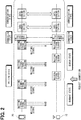
- FIG. 1 shows a rough structure of a vehicle 1 on which a mobile terminal position detection device 100 is mounted according to the present embodiment.
- the vehicle 1 is equipped with receivers 10 at seven locations.
- the number of receivers 10 mounted on the vehicle 1 is seven, but the number of receivers 10 is not limited to seven, and for example, more receivers 10 may be mounted.
- receivers 10 When there is a need to distinguish those receivers 10 from each other, those receivers 10 are referred to as a receiver 10a, a receiver 10b, a receiver 10c, a receiver 10d, a receiver 10e, a receiver 10f, and a receiver 10g, but when there is no need to distinguish those receivers from each other, those receivers are simply referred to as receivers 10 or receivers 10a to 10g.
- Those receivers 10a to 10g are each provided with an antenna for transmitting and receiving radio waves and a control unit connected to the antenna for controlling transmission and reception of the radio waves, and the control unit of each of the receivers 10a to 10g is connected to a mobile terminal position detection device 100.
- the mobile terminal position detection device 100 can receive the radio waves from the mobile terminal 20 existing outside or inside the vehicle 1, and can transmit the radio waves toward the mobile terminal 20, with the use of the receivers 10a to 10g. If the mobile terminal position detection device 100 detects the signal strength when the receivers 10a to 10g receive the radio waves from the mobile terminal 20, the mobile terminal position detection device 100 can determine the existence position of the mobile terminal 20.
- the signal strength of the radio waves changes due to an influence of the surrounding environment of the receivers 10 and the mobile terminal 20. For that reason, a large error may be included in the existence position of the mobile terminal 20 determined based on the signal strength, which makes it difficult to ensure positional accuracy to the extent distinguishable whether the mobile terminal 20 is present in the interior of the vehicle 1 or in the exterior of the vehicle 1.
- the number of receivers 10 is increased, thereby being capable of improving the detection accuracy of the existence position of the mobile terminal 20 as much as possible (at least in principle). Nevertheless, the process is not complicated at all.
- the mobile terminal position detection device 100 of the present embodiment having such excellent characteristics will be described, and a conventional method will be outlined as a preparation for the present embodiment.
- FIG. 2 illustrates a state in which the receiver 10 establishes a connection with the mobile terminal 20 in order to receive the radio waves from the mobile terminal 20.
- FIG. 2 as an example, a case of a communication standard in which a wireless communication is performed with the use of the radio waves in a frequency band of 2.4 GHz will be described, but other communication standards may be used.
- the communication standard illustrated in FIG. 2 employs a so-called master-client system, and the receivers 10 on a master side are in a dormant state for the purpose of reducing a power consumption while communication is not performed.
- the mobile terminal 20 on a client side transmits a waiting signal indicating that the mobile terminal 20 is waiting for connection in a predetermined cycle.
- the waiting signal includes, in addition to waiting for connection from the master side, information relating to the mobile terminal 20 itself, a function that can be provided to a device (in this example, the receiver 10) on the master side and the like. Accordingly, the receiver 10 on the master side can recognize the presence of the mobile terminal 20 by receiving the waiting signal and determine whether or not to connect to the mobile terminal 20.
- the waiting signal is not transmitted continuously, but is transmitted every time a predetermined time elapses.
- An elapsed time from the transmission of the waiting signal to the transmission again can be selected within a range of several tens of milliseconds to several seconds.
- the waiting signal is sometimes called an advertisement signal depending on the communication standard.
- the receiver 10 is connected to the mobile terminal position detection device 100, and when a request for connecting to the mobile terminal 20 is received from the mobile terminal position detection device 100, the receiver 10 is switched from the dormant state to a search state, and starts searching for the waiting signal.
- the waiting signal from the mobile terminal 20 is searched for a predetermined time, but when the waiting signal is not found, the search is temporarily interrupted, and the search for the waiting signal is started again after a predetermined time has elapsed.
- the reason why the search is performed every time a predetermined time elapses, rather than continuously searching until the waiting signal is found, is to reduce the power consumption of the receiver 10. That is, if the waiting signal cannot be received or if the waiting signal is not a waiting signal from the mobile terminal 20 even if the waiting signal has been received, it is considered that the state is likely to continue for a while, and therefore, even if the waiting signal is continuously received, an electric power is wastefully consumed. Therefore, once reception is interrupted to avoid the power consumption, and when a predetermined time has elapsed, the search for the waiting signal is started again.
- a period in which the receiver 10 searches for the waiting signal and a period in which the mobile terminal 20 transmits the waiting signal may be different from each other.
- a cycle in which the mobile terminal 20 transmits the waiting signal and a cycle in which the receiver 10 searches for the waiting signal are set to be different from each other. For that reason, the period in which the mobile terminal 20 transmits the waiting signal overlaps with the period in which the receiver 10 searches for the waiting signal, and the receiver 10 can receive the waiting signal of the mobile terminal 20.
- the receiver 10 When the receiver 10 receives the waiting signal from the mobile terminal 20, and determines to connect to the mobile terminal 20, the receiver 10 transmits a connection request signal requesting the connection. Then, the mobile terminal 20 which has received the connection request signal recognizes that the receiver 10 has been connected, terminates the waiting state, and shifts to a connection state, and starts a connection process for establishing the connection with the receiver 10. After transmitting the connection request signal, the receiver 10 also terminates the search state and shifts to the connection state, and starts a connection process for establishing a connection with the mobile terminal 20.
- the connection is established by exchanging various information necessary for wireless communication, such as identification numbers of each other, a frequency channel used for wireless communication, a communication interval, and data structure of the data to be communicated, and the like.
- both the mobile terminal 20 and the receiver 10 shift to the communication state and start a data communication.
- the mobile terminal 20 returns to the waiting state, the receiver 10 returns to the dormant state, and a series of processing described above is resumed.
- the receiver 10 and the mobile terminal 20 adopt a so-called master-client communication standard, so that the mobile terminal 20 on the client side has three states of "waiting state”, “connection state” and “communication state”, and the receiver 10 on the master side has four states of "dormant state”, “search state”, "connection state” and "communication state”.
- the mobile terminal 20 on the client side and the receiver 10 on the master side communicate with each other by switching those states so as to keep pace with each other.
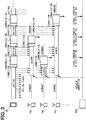
- FIG. 3 illustrates a state in which a conventional mobile terminal position detection device 500 detects the signal strength of the radio waves from the mobile terminal 20 in the receivers 10 (in FIG. 3 , the receivers 10a, 10b, 10c,...) installed at multiple locations. It is assumed that the conventional mobile terminal position detection device 500 is also connected to seven receivers 10a to 10g in the same manner as that of the mobile terminal position detection device 100 of the present embodiment described above with reference to FIG. 1 .
- the receiver 10 when there is no need to receive the radio waves from the mobile terminal 20, the receiver 10 is in the dormant state. Also, while the receiver 10 is in the dormant state, the mobile terminal 20 is in the waiting state, and transmits a waiting signal indicative of waiting for the connection from the receiver 10.
- the mobile terminal position detection device 500 requests the seven receivers 10a to 10g to connect to the mobile terminal 20. Then, the receivers 10a to 10g receive the request shift from the dormant state to the search state, and start searching for the waiting signal from the mobile terminal 20.
- the receivers 10a to 10g do not immediately find the mobile terminal 20 even when the receivers 10a to 10g enter the search state.
- the mobile terminal 20 cannot be found unless the receiver 10 starts searching for the waiting signal while the mobile terminal 20 is transmitting the waiting signal.
- FIG. 3 it is assumed that the receiver 10b has found the mobile terminal 20 at the earliest timing.
- the receiver 10b that has found the mobile terminal 20 transmits a connection request signal to the mobile terminal 20 and shifts to the "connection state".
- the mobile terminal 20 receives the connection request signal from the receiver 10b
- the mobile terminal 20 shifts to the "connection state” and establishes a connection between the receiver 10b and the mobile terminal 20.
- the connection is established in this manner, the mobile terminal 20 and the receiver 10b shift to the "communication state” and become in a state in which the mobile terminal 20 and the receiver 10b can communicate with each other.
- the receiver 10b detects the signal strength of the radio waves of the mobile terminal 20, outputs the signal strength to the mobile terminal position detection device 500, and then terminates the communication state and shifts to the dormant state. In response to the shift of the receiver 10b to the dormant state, the mobile terminal 20 connected to the receiver 10b shifts to the waiting state.
- the other receivers 10a and 10c to 10g are searching for the waiting signal from the mobile terminal 20 while maintaining the searching state.
- the mobile terminal 20 since the mobile terminal 20 does not transmit the waiting signal in the connection state and the communication state, the other receivers 10a and 10c to 10g cannot find the mobile terminal 20. Only after the mobile terminal 20 terminates a communication with the receiver 10b and returns to the waiting state, the mobile terminal 20 can be searched for.
- the receiver 10a has found the mobile terminal 20.
- the receiver 10a establishes a connection with the mobile terminal 20, starts a communication, detects the signal strength of the radio waves of the mobile terminal 20, and then outputs the detected signal strength to the mobile terminal position detection device 500.
- the mobile terminal 20 is not in the waiting state, and therefore the waiting signal is not transmitted.
- the other receivers 10c to 10g cannot find the mobile terminal 20, and only after the mobile terminal 20 terminates the communication with the receiver 10a and returns to the waiting state, the mobile terminal 20 can be searched.
- the mobile terminal position detection device 500 when the signal strength of the radio waves from the mobile terminal 20 is going to be detected by the multiple receivers 10, a time required for the detection inevitably increases. Further, as the number of receivers 10 is increased in an attempt to improve the positional accuracy of detecting the existence position of the mobile terminal 20, the time required for detection becomes longer. While there is a possibility that the mobile terminal 20 moves during this period, the mobile terminal position detection device 500 cannot determine whether or not the mobile terminal 20 is moving. As a result, the detection accuracy of the existing position is limited by the range in which the mobile terminal 20 can move, and it is eventually difficult to detect the existence position of the mobile terminal 20 with sufficient accuracy even if the number of receivers 10 is increased.
- the mobile terminal position detection device 100 of the present embodiment can detect the existence position of the mobile terminal 20 with sufficient accuracy by detecting the signal strength of the radio waves of the mobile terminal 20 with the multiple receivers 10.
- FIG. 4 shows a rough internal structure of the mobile terminal position detection device 100 according to the present embodiment.
- the mobile terminal position detection device 100 includes a communication unit 101, a connection request unit 102, a connection information acquisition unit 103, a connection information output unit 104, a signal strength acquisition unit 105, and an existence position detection unit 106.
- those "units” represent abstract concepts in which the inside of the mobile terminal position detection device 100 is classified for convenience, focusing on the functions of detecting the existence position of the mobile terminal based on the signal strength of the radio waves. Therefore, the inside of the mobile terminal position detection device 100 is not physically divided into those "unit”.
- Those "units" can be realized as a computer program executed by a CPU, can be realized as an electronic circuit including an LSI, or can be realized as a combination of the computer program with the electronic circuit.
- the communication unit 101 is connected to the receivers 10a to 10g by a cable, and can communicate with each other according to a predetermined communication standard.
- the connection request unit 102 requests the receivers 10a to 10g to connect to the mobile terminal 20.
- the request output by the connection request unit 102 is transmitted to the receivers 10a to 10g through the communication unit 101.
- the receivers 10a to 10g start searching for the mobile terminal 20 in order to connect to the mobile terminal 20 according to the request.
- the receiver 10 that has found the mobile terminal 20 acquires connection information used for connection with the mobile terminal 20, thereby establishing a connection with the mobile terminal 20.
- the connection information acquisition unit 103 acquires connection information from the receiver 10 that has established a connection with the mobile terminal 20.
- the connection information acquisition unit 103 may detect the receiver 10 whose connection is established and request the connection information, or when the connection request unit 102 needs to connect to the receivers 10a to 10g, the connection request unit 102 also request the receivers 10a to 10g to return the connection information when the connection is established.
- a function of outputting the acquired connection information to the mobile terminal position detection device 100 may be incorporated in advance in the receivers 10a to 10g.
- the connection information acquisition unit 103 outputs the connection information to the connection information output unit 104.
- the connection information output unit 104 Upon receiving the connection information, the connection information output unit 104 outputs the connection information toward the receiver 10 that has not yet been connected to the mobile terminal 20. In other words, even if the multiple receivers 10a to 10g attempt to simultaneously connect to the mobile terminal 20, those receivers 10a to 10g cannot be connected at the same time, and therefore, at the time when the connection information acquisition unit 103 acquires the connection information, there are receivers 10 that have not yet been connected to the mobile terminal 20. The connection information output unit 104 outputs the connection information to such receivers 10. The receiver 10 that has received the connection information is put into a state of being able to receive the radio waves from the mobile terminal 20, even though the receiver 10 is not connected to the mobile terminal 20.
- the signal strength acquisition unit 105 acquires the signal strength of the radio waves of the mobile terminal 20 detected by the receivers 10a to 10g. As described above, since all of the receivers 10a to 10g have already acquired the connection information, when the mobile terminal 20 outputs the radio waves, the receivers 10a to 10g can receive the radio waves and detect the signal strength. The signal strength acquisition unit 105 acquires the signal strengths detected by the receivers 10a to 10g, and outputs those signal strengths to the existence position detection unit 106.
- the existence position detection unit 106 detects the existence position of the mobile terminal 20 based on the signal strength acquired from the signal strength acquisition unit 105.
- the mobile terminal position detection device 100 of the present embodiment has various functions as described above, the detection accuracy of the existence position of the mobile terminal 20 can be improved by increasing the number of receivers 10.
- the processing executed by the mobile terminal position detection device 100 of the present embodiment to detect the existence position of the mobile terminal 20 will be described in detail.
- FIG. 5 is a flowchart of the mobile terminal position detection process executed by the mobile terminal position detection device 100 according to the present embodiment.
- the mobile terminal position detection process when the mobile terminal position detection process is started, first, it is determined whether or not the existence position of the mobile terminal 20 is detected (S100).
- the existence position is detected every time a predetermined time (for example, 5 seconds) elapses, but the existence position of the mobile terminal 20 may be detected when a request is received from another program.
- the mobile terminal 20 is put into the waiting state by repeating the same determination (S100).
- the receivers 10a to 10g connected to the mobile terminal position detection device 100 is requested to be connected to the mobile terminal 20 (S101).
- the receivers 10a to 10g which have received the request shift from the dormant state to the search state, and start searching for the waiting signal transmitted from the mobile terminal 20.
- the waiting signal cannot be always immediately received. Therefore, among the receivers 10a to 10g, the receiver 10 that first received the waiting signal connects to the mobile terminal 20 by first transmitting the connection request signal.
- the mobile terminal position detection device 100 When the mobile terminal position detection device 100 requests the receivers 10a to 10g to connect to the mobile terminal 20 (S101), the mobile terminal position detection device 100 determines whether or not there is a receiver 10 that has been connected to the mobile terminal 20 (S102). In the determination, whether or not the connection can be performed may be determined by inquiring of the respective receivers 10a to 10g from the mobile terminal position detection device 100, or when the connection is requested to the receivers 10a to 10g, a fact that the connection has been performed may be supplied as a reply, and the connection may be determined based on the presence or absence of the reply.
- connection information is acquired from the connected receiver (S104).
- the connection information is information used by the receiver 10 that has established a connection with the mobile terminal 20 (that is, the connected receiver) to communicate with the mobile terminal 20.
- the content of the connection information differs depending on the communication standard, but includes, for example, identification numbers of each other, a frequency channel used for a wireless communication, a communication interval, a data structure of data to be communicated, and the like.
- an encryption key is also included in the connection information.
- the mobile terminal position detection device 100 Upon acquiring the connection information from the connected receiver in this way (S104), the mobile terminal position detection device 100 outputs the connection information to a receiver 10 (hereinafter referred to as an unconnected receiver) that has not yet been connected to the mobile terminal 20 (hereinafter referred to as an unconnected receiver) (S105).
- the connection information is information used by the receiver 10 first connected to the mobile terminal 20 among the receivers 10a to 10g for communication with the mobile terminal 20, and the connection information is output to another receiver 10 that is not yet connected to the mobile terminal 20.
- FIG. 6 shows a state in which the mobile terminal position detection device 100 of the present embodiment acquires the connection information from the connected receiver and outputs the acquired connection information to the unconnected receiver.
- (a) in FIG. 6 shows a state in which the receiver 10b first finds the mobile terminal 20 among the receivers 10a to 10g that have searched for the mobile terminal 20, and transmits a connection request signal to the mobile terminal 20.
- the mobile terminal 20 that has received the connection request signal shifts from the waiting state for transmitting the waiting signal to the connection state, and transmits the connection information for establishing the connection. Then, the receiver 10b establishes a connection with the mobile terminal 20 by receiving the transmitted connection information. Therefore, in an example shown in FIG. 6 , the receiver 10b is a connected receiver, and the receiver 10a and the receivers 10c to 10g are unconnected receivers. When the receiver 10b has established the connection with the mobile terminal 20, the receiver 10b outputs the connection information used for communication with the mobile terminal 20 to the mobile terminal position detection device 100.
- the mobile terminal position detection device 100 outputs the acquired connection information to the receivers 10a and 10c to 10g that have not yet been connected to the mobile terminal 20.
- the receiver 10a and the receivers 10c to 10g shift from the search state to the reception state in which the radio waves of the mobile terminal 20 can be received.
- the conventional method needs to shift from the search state to the communication state through the connection state, but in the present embodiment, the receiver 10 a and the receivers 10c to 10g shift to the reception state without passing through the connection state. Further, since the receiver 10b is shifted to the communication state through the connection state, the radio waves from the mobile terminal 20 can be received.
- the receiver 10 in the reception state has not established the connection with the mobile terminal 20, it is desirable to assume that the transmission to the mobile terminal 20 cannot be performed.
- the receiver 10 that has established the connection transmits to the mobile terminal 20
- the receiver 10 that has not established the connection can be prevented from transmitting the radio waves to the mobile terminal 20 and causing so-called communication collision.
- connection information is output to the unconnected receivers (in an example shown in FIG. 6 , the receiver 10a and the receivers 10c to 10g) (S105 in FIG. 5 ), when the radio waves of the mobile terminal 20 can be received by the receivers 10a to 10g, the signal strength of the radio waves detected by the connected receiver (in the example shown in FIG. 6 , the receiver 10b) is acquired (S106). Subsequently, the signal strength of the radio waves detected by the unconnected receivers (in the examples shown in FIG. 6 , the receiver 10a and the receivers 10c to 10g) is acquired (S107).
- the existence position of the mobile terminal 20 is detected based on the signal strengths acquired by the respective receivers 10a to 10g (S108).
- a method conventionally used can be applied to the method of detecting the existence position of the mobile terminal 20 based on the signal strength.
- the mobile terminal position detection device 100 of the present embodiment detects the existence position of the mobile terminal 20 as described above, the existence position of the mobile terminal 20 can be detected with sufficient accuracy even though the signal strength of the radio waves of the mobile terminal 20 is used by the multiple receivers 10.
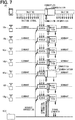
- FIG. 7 shows the reason why the mobile terminal position detection device 100 of the present embodiment can detect the existence position of the mobile terminal 20 with sufficient accuracy.
- the mobile terminal position detection device 100 requests the receivers 10a to 10g to connect to the mobile terminal 20 in an attempt to detect the existence position of the mobile terminal 20, the receivers 10a to 10g which have been in the dormant state until then start searching for the waiting signal transmitted by the mobile terminal 20.
- the waiting signal transmitted by the mobile terminal 20 is represented by a broken line arrow.
- FIG. 7 shows a case where the receiver 10e receives the waiting signal first, and illustrates a state where the mobile terminal 20 transmits the connection information to the receiver 10e and a state where the receiver 10e outputs the connection information received from the mobile terminal 20 to the mobile terminal position detection device 100 by hatched arrows.
- the mobile terminal position detection device 100 Upon receiving the connection information from the receiver 10e, the mobile terminal position detection device 100 outputs the connection information to the receivers 10a to 10d, 10f, and 10g. As a result, the receivers 10a to 10d, 10f, and 10g are in a reception state capable of receiving the radio waves from the mobile terminal 20. Since the receiver 10e receiving the connection information from the mobile terminal 20 is in the communication state, the receiver 10e can also receive radio waves from the mobile terminal 20.
- the signal strength of the radio waves is detected in a state in which all the receivers 10a to 10g can receive the radio waves from the mobile terminal 20.
- the signal strength when the same radio waves output from the mobile terminal 20 are received by the receivers 10a to 10g can be detected. This process does not change even if the number of receivers 10 increases.
- the existence position of the mobile terminal 20 can be detected with sufficient accuracy.
- the mobile terminal position detection device 100 of the present embodiment has been described as being connected to the receivers 10a to 10g through the communication unit 101. In that case, the communication performed between the communication unit 101 and the receivers 10a to 10g is also performed in accordance with the communication rule of the master-client system. Further, when the existence position of the mobile terminal 20 is detected, connection is requested to the receivers 10a to 10g through the communication unit 101 at the same time.
- the receiver 10a capable of communicating with the mobile terminal position detection device 100 without passing through the communication device 101 may be provided, and the other receivers 10 (that is, the receivers 10b to 10g) may communicate with the mobile terminal position detection device 100 through the communication unit 101.
- the other receivers 10 that is, the receivers 10b to 10g
- connection may be requested to the receiver 10a without requesting connection to the receivers 10b to 10g.
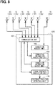
- FIG. 8 shows a rough internal structure of a mobile terminal position detection device 150 in the modification.
- the mobile terminal position detection device 150 according to the modification differs from the mobile terminal position detection device 100 of the present example described above with reference to FIG. 4 in that the receiver 10a is directly connected to the connection request unit 102, but the other configurations are the same.
- the receiver 10a and the connection request unit 102 are directly connected to each other. For that reason, the communication can be performed at high speed without being restricted by the communication rule of the master-client system such as when the receivers 10b to 10g communicate with the communication unit 101.
- FIG. 9 shows a flowchart of the mobile terminal position detection process executed by the mobile terminal position detection device 150 according to the modification.
- This processing is greatly different from the mobile terminal position detection processing described above with reference to FIG. 5 in that a connection to the mobile terminal 20 is requested to a predetermined receiver 10 (in this example, the receiver 10a), but is not requested to the other receivers 10 (in this example, the receivers 10b to 10g).
- the mobile terminal position detection processing of the modification will be briefly described focusing on the above difference.
- the receiver 10a is requested to connect to the mobile terminal 20 (S151).
- S151 the mobile terminal position detection device 150 in a so-called peer-to-peer manner, a communication can be performed at a higher speed than that of the receivers 10b to 10g.
- the predetermined receiver 10a determines whether or not the predetermined receiver 10a has been connected to the mobile terminal 20 (S152), and if not connected (no in S152), it is determined whether or not a predetermined time has elapsed after requesting the connection (S153). As a result, when the predetermined period has not elapsed (no in S153), it is determined whether or not the receiver 10a has been connected to the mobile terminal 20 (S152). If the predetermined period of time has elapsed (yes in S153) while repeating such a determination, it is considered that there is no mobile terminal 20 to be connected, so that the process returns to the beginning of the process and the series of processes described above is resumed.
- the predetermined receiver 10 in this example, the receiver 10a
- the connection information is acquired from the receiver 10a (S154), and then the connection information is output toward the other receivers 10 (in this example, the receivers 10b to 10g) (S155).
- those receivers 10b to 10g are also in a reception state capable of receiving the radio waves of the mobile terminal 20.
- the receivers 10a to 10g can receive the radio waves of the mobile terminal 20
- the signal strength of the radio waves detected by the receiver 10a is acquired (S156)
- the signal strength of the radio waves detected by the other receivers 10b to 10g is acquired (S157).
- the existence position of the mobile terminal 20 is output to the outside (S159), and the process returns to S150 which is the beginning of the process.
- the existence position of the mobile terminal 20 can be detected more quickly.
- each section is expressed as, for example, S100. Further, each section may be divided into several subsections, while several sections may be combined into one section. Furthermore, each section thus configured may be referred to as a device, module, or means.
Landscapes
- Engineering & Computer Science (AREA)
- Computer Networks & Wireless Communication (AREA)
- Signal Processing (AREA)
- Physics & Mathematics (AREA)
- General Physics & Mathematics (AREA)
- Radar, Positioning & Navigation (AREA)
- Remote Sensing (AREA)
- Mobile Radio Communication Systems (AREA)
- Position Fixing By Use Of Radio Waves (AREA)
Applications Claiming Priority (2)
| Application Number | Priority Date | Filing Date | Title |
|---|---|---|---|
| JP2017080082A JP6711309B2 (ja) | 2017-04-13 | 2017-04-13 | 携帯端末位置検出装置、携帯端末位置検出方法 |
| PCT/JP2018/008208 WO2018190026A1 (ja) | 2017-04-13 | 2018-03-05 | 携帯端末位置検出装置、携帯端末位置検出方法 |
Publications (3)
| Publication Number | Publication Date |
|---|---|
| EP3611531A1 EP3611531A1 (en) | 2020-02-19 |
| EP3611531A4 EP3611531A4 (en) | 2020-05-27 |
| EP3611531B1 true EP3611531B1 (en) | 2021-06-30 |
Family
ID=63792977
Family Applications (1)
| Application Number | Title | Priority Date | Filing Date |
|---|---|---|---|
| EP18784305.7A Active EP3611531B1 (en) | 2017-04-13 | 2018-03-05 | Mobile terminal position detection device and mobile terminal position detection method |
Country Status (5)
| Country | Link |
|---|---|
| US (1) | US10674314B2 (enExample) |
| EP (1) | EP3611531B1 (enExample) |
| JP (1) | JP6711309B2 (enExample) |
| KR (1) | KR102210122B1 (enExample) |
| WO (1) | WO2018190026A1 (enExample) |
Families Citing this family (3)
| Publication number | Priority date | Publication date | Assignee | Title |
|---|---|---|---|---|
| JP7297785B2 (ja) * | 2018-11-09 | 2023-06-26 | 株式会社ソニー・インタラクティブエンタテインメント | 通信装置、電子機器および無線接続方法 |
| JP7534197B2 (ja) * | 2020-11-26 | 2024-08-14 | 株式会社東海理化電機製作所 | 位置判定システム及び位置判定方法 |
| JP7631785B2 (ja) * | 2020-12-21 | 2025-02-19 | 株式会社Soken | 車両側ユニット及び位置関係特定システム |
Family Cites Families (38)
| Publication number | Priority date | Publication date | Assignee | Title |
|---|---|---|---|---|
| US6690940B1 (en) * | 2000-09-22 | 2004-02-10 | James W. Brown | System for selective prevention of non-emergency use of an electronic device |
| JP2003248045A (ja) * | 2002-02-22 | 2003-09-05 | Alpine Electronics Inc | 車室内乗員位置検出装置および車載機器制御システム |
| JP4015963B2 (ja) * | 2003-03-24 | 2007-11-28 | 株式会社日立製作所 | 位置計算方法、受信装置及び位置計算装置 |
| JP3955290B2 (ja) * | 2004-06-30 | 2007-08-08 | ソニー・エリクソン・モバイルコミュニケーションズ株式会社 | 通信システム及び通信端末装置 |
| JP2009177588A (ja) * | 2008-01-25 | 2009-08-06 | Fujitsu Ten Ltd | 車載装置および位置検出方法 |
| US8045961B2 (en) | 2009-06-22 | 2011-10-25 | Mourad Ben Ayed | Systems for wireless authentication based on bluetooth proximity |
| DE102010034976A1 (de) | 2010-08-20 | 2012-02-23 | Hella Kgaa Hueck & Co. | Anordnung zur Berechtigungskontrolle, insbesondere für Kraftfahrzeuge |
| US9041556B2 (en) * | 2011-10-20 | 2015-05-26 | Apple Inc. | Method for locating a vehicle |
| US9241235B2 (en) | 2013-03-14 | 2016-01-19 | Voxx International Corporation | Passive entry cell phone and method and system therefor |
| EP3072317B1 (en) | 2013-11-22 | 2018-05-16 | Qualcomm Incorporated | System and method for configuring an interior of a vehicle based on preferences provided with multiple mobile computing devices within the vehicle |
| US20150161832A1 (en) | 2013-12-05 | 2015-06-11 | Ford Global Technologies, Llc | Method and Apparatus for Virtual Key Delivery |
| JP6241299B2 (ja) | 2014-02-03 | 2017-12-06 | 株式会社デンソー | 車両電子キーシステム |
| JP6258744B2 (ja) * | 2014-03-27 | 2018-01-10 | 株式会社デンソー | 測定システム |
| US9595145B2 (en) | 2014-04-23 | 2017-03-14 | Panasonic Automotive Systems Company Of America, Division Of Panasonic Corporation Of North America | System for assigning a smartphone as a temporary key for a vehicle |
| US20150356797A1 (en) | 2014-06-05 | 2015-12-10 | International Business Machines Corporation | Virtual key fob with transferable user data profile |
| BR102014017465A2 (pt) | 2014-07-16 | 2016-02-16 | Segtrônica Comércio De Equipamentos E Produtos Ltda | fechadura eletromecânica acionada por rádio frequência |
| WO2016023901A1 (en) * | 2014-08-12 | 2016-02-18 | Philips Lighting Holding B.V. | Method and apparatus for locating of a mobile device |
| US10002479B2 (en) | 2014-10-01 | 2018-06-19 | Continental Intelligent Transportation Systems, LLC | End to end system for service delivery to and from a vehicle using a dongle |
| US20160150407A1 (en) | 2014-11-26 | 2016-05-26 | Wind River Systems, Inc. | Method And System For Connecting A Mobile Communication Device To An Automobile |
| FR3030818B1 (fr) | 2014-12-23 | 2016-12-23 | Valeo Comfort & Driving Assistance | Procede de transmission securisee d'une cle virtuelle et methode d'authentification d'un terminal mobile |
| CN104574593B (zh) | 2014-12-24 | 2017-02-22 | 浙江银江研究院有限公司 | 一种基于蓝牙通信的虚拟钥匙及其防盗锁系统、应用方法 |
| FR3034550B1 (fr) | 2015-04-01 | 2018-09-21 | Valeo Comfort And Driving Assistance | Procede de chargement d'une cle au sein d'un terminal utilisateur et terminal utilisateur associe |
| CN106486771A (zh) | 2015-08-28 | 2017-03-08 | 中兴通讯股份有限公司 | 多频带微线条天线 |
| US10437977B2 (en) | 2015-10-13 | 2019-10-08 | Etas Embedded Systems Canada Inc. | System and method for digital key sharing for access control |
| US10412088B2 (en) | 2015-11-09 | 2019-09-10 | Silvercar, Inc. | Vehicle access systems and methods |
| EP4093062B1 (en) | 2016-04-15 | 2025-06-04 | Denso Corporation | System and method for establishing real-time location |
| US9875591B2 (en) | 2016-04-26 | 2018-01-23 | Ford Global Techologies, Llc | Systems and methods for phone-as-a-key range extension |
| DE102016217318A1 (de) | 2016-07-26 | 2018-02-01 | Volkswagen Aktiengesellschaft | Verfahren, Computerprogramm und Vorrichtung zum Überprüfen einer Berechtigung eines mobilen Kommunikationsgeräts |
| US9688247B1 (en) | 2016-08-03 | 2017-06-27 | Ford Global Technologies, Llc | Method and apparatus for digital temporary vehicle key utilization |
| WO2018040641A1 (zh) | 2016-08-31 | 2018-03-08 | 长城汽车股份有限公司 | 移动终端、车辆终端、虚拟钥匙分享方法及系统 |
| US9894492B1 (en) | 2016-09-22 | 2018-02-13 | Ford Global Technologies, Llc | System and method for determining mobile device location relative to vehicle cabin |
| US10328899B2 (en) | 2016-10-12 | 2019-06-25 | Denso International America, Inc. | Localization and passive entry / passive start systems and methods for vehicles |
| US10328898B2 (en) | 2016-10-12 | 2019-06-25 | Denso International America, Inc. | Passive entry / passive start systems and methods for vehicles |
| US10189443B2 (en) | 2016-11-10 | 2019-01-29 | GM Global Technology Operations LLC | Virtual key for vehicle servicing |
| US9988016B1 (en) | 2016-12-07 | 2018-06-05 | Ford Global Technologies, Llc | Authentication of mobile devices for vehicle communication |
| US10862198B2 (en) | 2017-03-14 | 2020-12-08 | R.A. Miller Industries, Inc. | Wideband, low profile, small area, circular polarized uhf antenna |
| US10244476B2 (en) | 2017-04-13 | 2019-03-26 | Ford Global Technologies, Llc | Reducing power consumption for phone as a key (PAAK) vehicle system |
| US10328900B1 (en) | 2017-12-04 | 2019-06-25 | Lear Corporation | System and methods for vehicle passive keyless entry triggered by smartphone proximity detection |
-
2017
- 2017-04-13 JP JP2017080082A patent/JP6711309B2/ja active Active
-
2018
- 2018-03-05 EP EP18784305.7A patent/EP3611531B1/en active Active
- 2018-03-05 KR KR1020197025981A patent/KR102210122B1/ko active Active
- 2018-03-05 WO PCT/JP2018/008208 patent/WO2018190026A1/ja not_active Ceased
-
2019
- 2019-09-03 US US16/559,422 patent/US10674314B2/en active Active
Also Published As
| Publication number | Publication date |
|---|---|
| JP2018179773A (ja) | 2018-11-15 |
| KR102210122B1 (ko) | 2021-02-01 |
| WO2018190026A1 (ja) | 2018-10-18 |
| EP3611531A4 (en) | 2020-05-27 |
| EP3611531A1 (en) | 2020-02-19 |
| US20190394616A1 (en) | 2019-12-26 |
| US10674314B2 (en) | 2020-06-02 |
| KR20190109544A (ko) | 2019-09-25 |
| JP6711309B2 (ja) | 2020-06-17 |
Similar Documents
| Publication | Publication Date | Title |
|---|---|---|
| US11310640B2 (en) | Method for vehicle-to-vehicle communication | |
| US10674314B2 (en) | Mobile terminal position detection device and mobile terminal position detection method | |
| US20210377913A1 (en) | Resource switching method, and resource allocation method, apparatus, device and system | |
| US20080002624A1 (en) | Wireless communication system, wireless communication apparatus, wireless communication method, and recording medium | |
| US20200185966A1 (en) | Electronic apparatus and method | |
| JP5897405B2 (ja) | 無線端末がアクセスポイントを探索するタイミングを制御するアクセスポイント発見方法、システム及び無線端末 | |
| US10698075B2 (en) | Mobile-terminal detection apparatus and mobile-terminal detection method | |
| US20190322242A1 (en) | Authentication system, portable device, authentication device and registration method | |
| US20230336256A1 (en) | Vehicle unit and positional relationship identification system | |
| JP2015189244A (ja) | 携帯機および車両用制御システム | |
| WO2016129245A1 (ja) | 到来方向推定システム、測定装置 | |
| EP4271022B1 (en) | Communication device, control method, and program | |
| EP3562174A1 (en) | Mobile device detection apparatus and mobile device detection method | |
| US11172546B2 (en) | Wireless device adapted to perform wireless communication | |
| JP6522902B2 (ja) | 位置推定装置 | |
| US20220264327A1 (en) | Communication device and non-transitory computer readable storage medium | |
| CN118400002A (zh) | 通信设备及通信方法 | |
| CN101222739A (zh) | 一种驻波检测的方法、装置和基站 | |
| JP6447749B2 (ja) | 運転支援情報伝送システム、受信機、運転支援システム、及び運転支援情報伝送方法 | |
| KR100850910B1 (ko) | 블루투스 디바이스를 연결하기 위한 장치 및 방법 | |
| JPH05168059A (ja) | 移動体通信方法 | |
| JPH1146176A (ja) | 通信制御方式、及び時分割多重接続通信システム | |
| CN114270939A (zh) | 直通链路同步信号的发送方法和装置 | |
| US12039397B2 (en) | Systems, methods, and devices for wireless communication device-based detection of radio frequency identification devices | |
| JP2015189245A (ja) | 携帯機、制御装置、および車両用制御システム |
Legal Events
| Date | Code | Title | Description |
|---|---|---|---|
| STAA | Information on the status of an ep patent application or granted ep patent |
Free format text: STATUS: THE INTERNATIONAL PUBLICATION HAS BEEN MADE |
|
| PUAI | Public reference made under article 153(3) epc to a published international application that has entered the european phase |
Free format text: ORIGINAL CODE: 0009012 |
|
| STAA | Information on the status of an ep patent application or granted ep patent |
Free format text: STATUS: REQUEST FOR EXAMINATION WAS MADE |
|
| 17P | Request for examination filed |
Effective date: 20190701 |
|
| AK | Designated contracting states |
Kind code of ref document: A1 Designated state(s): AL AT BE BG CH CY CZ DE DK EE ES FI FR GB GR HR HU IE IS IT LI LT LU LV MC MK MT NL NO PL PT RO RS SE SI SK SM TR |
|
| AX | Request for extension of the european patent |
Extension state: BA ME |
|
| A4 | Supplementary search report drawn up and despatched |
Effective date: 20200428 |
|
| RIC1 | Information provided on ipc code assigned before grant |
Ipc: G01S 5/02 20100101AFI20200421BHEP Ipc: H04W 4/48 20180101ALI20200421BHEP Ipc: G01S 5/14 20060101ALN20200421BHEP Ipc: H04W 4/02 20180101ALI20200421BHEP Ipc: H04W 64/00 20090101ALI20200421BHEP |
|
| DAV | Request for validation of the european patent (deleted) | ||
| DAX | Request for extension of the european patent (deleted) | ||
| RIC1 | Information provided on ipc code assigned before grant |
Ipc: H04W 4/02 20180101ALI20200803BHEP Ipc: G01S 5/02 20100101AFI20200803BHEP Ipc: G01S 11/06 20060101ALI20200803BHEP Ipc: H04W 64/00 20090101ALI20200803BHEP Ipc: H04W 4/48 20180101ALI20200803BHEP Ipc: G01S 5/14 20060101ALN20200803BHEP |
|
| REG | Reference to a national code |
Ref country code: DE Ref legal event code: R079 Ref document number: 602018019473 Country of ref document: DE Free format text: PREVIOUS MAIN CLASS: G01S0005140000 Ipc: G01S0005020000 |
|
| RIC1 | Information provided on ipc code assigned before grant |
Ipc: H04W 4/48 20180101ALI20201217BHEP Ipc: H04W 64/00 20090101ALI20201217BHEP Ipc: G01S 5/02 20100101AFI20201217BHEP Ipc: H04W 4/02 20180101ALI20201217BHEP Ipc: G01S 5/14 20060101ALN20201217BHEP Ipc: G01S 11/06 20060101ALI20201217BHEP |
|
| GRAP | Despatch of communication of intention to grant a patent |
Free format text: ORIGINAL CODE: EPIDOSNIGR1 |
|
| STAA | Information on the status of an ep patent application or granted ep patent |
Free format text: STATUS: GRANT OF PATENT IS INTENDED |
|
| INTG | Intention to grant announced |
Effective date: 20210125 |
|
| GRAS | Grant fee paid |
Free format text: ORIGINAL CODE: EPIDOSNIGR3 |
|
| GRAA | (expected) grant |
Free format text: ORIGINAL CODE: 0009210 |
|
| STAA | Information on the status of an ep patent application or granted ep patent |
Free format text: STATUS: THE PATENT HAS BEEN GRANTED |
|
| AK | Designated contracting states |
Kind code of ref document: B1 Designated state(s): AL AT BE BG CH CY CZ DE DK EE ES FI FR GB GR HR HU IE IS IT LI LT LU LV MC MK MT NL NO PL PT RO RS SE SI SK SM TR |
|
| REG | Reference to a national code |
Ref country code: CH Ref legal event code: EP |
|
| RIN1 | Information on inventor provided before grant (corrected) |
Inventor name: YAMAGUCHI, TAICHI |
|
| REG | Reference to a national code |
Ref country code: AT Ref legal event code: REF Ref document number: 1406831 Country of ref document: AT Kind code of ref document: T Effective date: 20210715 |
|
| REG | Reference to a national code |
Ref country code: DE Ref legal event code: R096 Ref document number: 602018019473 Country of ref document: DE |
|
| REG | Reference to a national code |
Ref country code: IE Ref legal event code: FG4D |
|
| REG | Reference to a national code |
Ref country code: LT Ref legal event code: MG9D |
|
| PG25 | Lapsed in a contracting state [announced via postgrant information from national office to epo] |
Ref country code: BG Free format text: LAPSE BECAUSE OF FAILURE TO SUBMIT A TRANSLATION OF THE DESCRIPTION OR TO PAY THE FEE WITHIN THE PRESCRIBED TIME-LIMIT Effective date: 20210930 Ref country code: HR Free format text: LAPSE BECAUSE OF FAILURE TO SUBMIT A TRANSLATION OF THE DESCRIPTION OR TO PAY THE FEE WITHIN THE PRESCRIBED TIME-LIMIT Effective date: 20210630 Ref country code: FI Free format text: LAPSE BECAUSE OF FAILURE TO SUBMIT A TRANSLATION OF THE DESCRIPTION OR TO PAY THE FEE WITHIN THE PRESCRIBED TIME-LIMIT Effective date: 20210630 |
|
| REG | Reference to a national code |
Ref country code: NL Ref legal event code: MP Effective date: 20210630 |
|
| REG | Reference to a national code |
Ref country code: AT Ref legal event code: MK05 Ref document number: 1406831 Country of ref document: AT Kind code of ref document: T Effective date: 20210630 |
|
| PG25 | Lapsed in a contracting state [announced via postgrant information from national office to epo] |
Ref country code: GR Free format text: LAPSE BECAUSE OF FAILURE TO SUBMIT A TRANSLATION OF THE DESCRIPTION OR TO PAY THE FEE WITHIN THE PRESCRIBED TIME-LIMIT Effective date: 20211001 Ref country code: SE Free format text: LAPSE BECAUSE OF FAILURE TO SUBMIT A TRANSLATION OF THE DESCRIPTION OR TO PAY THE FEE WITHIN THE PRESCRIBED TIME-LIMIT Effective date: 20210630 Ref country code: RS Free format text: LAPSE BECAUSE OF FAILURE TO SUBMIT A TRANSLATION OF THE DESCRIPTION OR TO PAY THE FEE WITHIN THE PRESCRIBED TIME-LIMIT Effective date: 20210630 Ref country code: LV Free format text: LAPSE BECAUSE OF FAILURE TO SUBMIT A TRANSLATION OF THE DESCRIPTION OR TO PAY THE FEE WITHIN THE PRESCRIBED TIME-LIMIT Effective date: 20210630 Ref country code: NO Free format text: LAPSE BECAUSE OF FAILURE TO SUBMIT A TRANSLATION OF THE DESCRIPTION OR TO PAY THE FEE WITHIN THE PRESCRIBED TIME-LIMIT Effective date: 20210930 |
|
| PG25 | Lapsed in a contracting state [announced via postgrant information from national office to epo] |
Ref country code: SK Free format text: LAPSE BECAUSE OF FAILURE TO SUBMIT A TRANSLATION OF THE DESCRIPTION OR TO PAY THE FEE WITHIN THE PRESCRIBED TIME-LIMIT Effective date: 20210630 Ref country code: EE Free format text: LAPSE BECAUSE OF FAILURE TO SUBMIT A TRANSLATION OF THE DESCRIPTION OR TO PAY THE FEE WITHIN THE PRESCRIBED TIME-LIMIT Effective date: 20210630 Ref country code: ES Free format text: LAPSE BECAUSE OF FAILURE TO SUBMIT A TRANSLATION OF THE DESCRIPTION OR TO PAY THE FEE WITHIN THE PRESCRIBED TIME-LIMIT Effective date: 20210630 Ref country code: SM Free format text: LAPSE BECAUSE OF FAILURE TO SUBMIT A TRANSLATION OF THE DESCRIPTION OR TO PAY THE FEE WITHIN THE PRESCRIBED TIME-LIMIT Effective date: 20210630 Ref country code: PT Free format text: LAPSE BECAUSE OF FAILURE TO SUBMIT A TRANSLATION OF THE DESCRIPTION OR TO PAY THE FEE WITHIN THE PRESCRIBED TIME-LIMIT Effective date: 20211102 Ref country code: RO Free format text: LAPSE BECAUSE OF FAILURE TO SUBMIT A TRANSLATION OF THE DESCRIPTION OR TO PAY THE FEE WITHIN THE PRESCRIBED TIME-LIMIT Effective date: 20210630 Ref country code: NL Free format text: LAPSE BECAUSE OF FAILURE TO SUBMIT A TRANSLATION OF THE DESCRIPTION OR TO PAY THE FEE WITHIN THE PRESCRIBED TIME-LIMIT Effective date: 20210630 Ref country code: AT Free format text: LAPSE BECAUSE OF FAILURE TO SUBMIT A TRANSLATION OF THE DESCRIPTION OR TO PAY THE FEE WITHIN THE PRESCRIBED TIME-LIMIT Effective date: 20210630 Ref country code: CZ Free format text: LAPSE BECAUSE OF FAILURE TO SUBMIT A TRANSLATION OF THE DESCRIPTION OR TO PAY THE FEE WITHIN THE PRESCRIBED TIME-LIMIT Effective date: 20210630 |
|
| PG25 | Lapsed in a contracting state [announced via postgrant information from national office to epo] |
Ref country code: PL Free format text: LAPSE BECAUSE OF FAILURE TO SUBMIT A TRANSLATION OF THE DESCRIPTION OR TO PAY THE FEE WITHIN THE PRESCRIBED TIME-LIMIT Effective date: 20210630 |
|
| REG | Reference to a national code |
Ref country code: DE Ref legal event code: R097 Ref document number: 602018019473 Country of ref document: DE |
|
| PG25 | Lapsed in a contracting state [announced via postgrant information from national office to epo] |
Ref country code: DK Free format text: LAPSE BECAUSE OF FAILURE TO SUBMIT A TRANSLATION OF THE DESCRIPTION OR TO PAY THE FEE WITHIN THE PRESCRIBED TIME-LIMIT Effective date: 20210630 |
|
| PLBE | No opposition filed within time limit |
Free format text: ORIGINAL CODE: 0009261 |
|
| STAA | Information on the status of an ep patent application or granted ep patent |
Free format text: STATUS: NO OPPOSITION FILED WITHIN TIME LIMIT |
|
| PG25 | Lapsed in a contracting state [announced via postgrant information from national office to epo] |
Ref country code: AL Free format text: LAPSE BECAUSE OF FAILURE TO SUBMIT A TRANSLATION OF THE DESCRIPTION OR TO PAY THE FEE WITHIN THE PRESCRIBED TIME-LIMIT Effective date: 20210630 |
|
| 26N | No opposition filed |
Effective date: 20220331 |
|
| PG25 | Lapsed in a contracting state [announced via postgrant information from national office to epo] |
Ref country code: IT Free format text: LAPSE BECAUSE OF FAILURE TO SUBMIT A TRANSLATION OF THE DESCRIPTION OR TO PAY THE FEE WITHIN THE PRESCRIBED TIME-LIMIT Effective date: 20210630 |
|
| PG25 | Lapsed in a contracting state [announced via postgrant information from national office to epo] |
Ref country code: MC Free format text: LAPSE BECAUSE OF FAILURE TO SUBMIT A TRANSLATION OF THE DESCRIPTION OR TO PAY THE FEE WITHIN THE PRESCRIBED TIME-LIMIT Effective date: 20210630 |
|
| REG | Reference to a national code |
Ref country code: CH Ref legal event code: PL |
|
| GBPC | Gb: european patent ceased through non-payment of renewal fee |
Effective date: 20220305 |
|
| REG | Reference to a national code |
Ref country code: BE Ref legal event code: MM Effective date: 20220331 |
|
| PG25 | Lapsed in a contracting state [announced via postgrant information from national office to epo] |
Ref country code: LU Free format text: LAPSE BECAUSE OF NON-PAYMENT OF DUE FEES Effective date: 20220305 Ref country code: LI Free format text: LAPSE BECAUSE OF NON-PAYMENT OF DUE FEES Effective date: 20220331 Ref country code: IE Free format text: LAPSE BECAUSE OF NON-PAYMENT OF DUE FEES Effective date: 20220305 Ref country code: GB Free format text: LAPSE BECAUSE OF NON-PAYMENT OF DUE FEES Effective date: 20220305 Ref country code: CH Free format text: LAPSE BECAUSE OF NON-PAYMENT OF DUE FEES Effective date: 20220331 |
|
| PG25 | Lapsed in a contracting state [announced via postgrant information from national office to epo] |
Ref country code: BE Free format text: LAPSE BECAUSE OF NON-PAYMENT OF DUE FEES Effective date: 20220331 |
|
| PG25 | Lapsed in a contracting state [announced via postgrant information from national office to epo] |
Ref country code: LT Free format text: LAPSE BECAUSE OF FAILURE TO SUBMIT A TRANSLATION OF THE DESCRIPTION OR TO PAY THE FEE WITHIN THE PRESCRIBED TIME-LIMIT Effective date: 20210630 |
|
| PG25 | Lapsed in a contracting state [announced via postgrant information from national office to epo] |
Ref country code: MK Free format text: LAPSE BECAUSE OF FAILURE TO SUBMIT A TRANSLATION OF THE DESCRIPTION OR TO PAY THE FEE WITHIN THE PRESCRIBED TIME-LIMIT Effective date: 20210630 Ref country code: CY Free format text: LAPSE BECAUSE OF FAILURE TO SUBMIT A TRANSLATION OF THE DESCRIPTION OR TO PAY THE FEE WITHIN THE PRESCRIBED TIME-LIMIT Effective date: 20210630 |
|
| PG25 | Lapsed in a contracting state [announced via postgrant information from national office to epo] |
Ref country code: HU Free format text: LAPSE BECAUSE OF FAILURE TO SUBMIT A TRANSLATION OF THE DESCRIPTION OR TO PAY THE FEE WITHIN THE PRESCRIBED TIME-LIMIT; INVALID AB INITIO Effective date: 20180305 |
|
| PG25 | Lapsed in a contracting state [announced via postgrant information from national office to epo] |
Ref country code: TR Free format text: LAPSE BECAUSE OF FAILURE TO SUBMIT A TRANSLATION OF THE DESCRIPTION OR TO PAY THE FEE WITHIN THE PRESCRIBED TIME-LIMIT Effective date: 20210630 |
|
| PG25 | Lapsed in a contracting state [announced via postgrant information from national office to epo] |
Ref country code: MT Free format text: LAPSE BECAUSE OF FAILURE TO SUBMIT A TRANSLATION OF THE DESCRIPTION OR TO PAY THE FEE WITHIN THE PRESCRIBED TIME-LIMIT Effective date: 20210630 |
|
| PGFP | Annual fee paid to national office [announced via postgrant information from national office to epo] |
Ref country code: DE Payment date: 20250319 Year of fee payment: 8 |
|
| PGFP | Annual fee paid to national office [announced via postgrant information from national office to epo] |
Ref country code: FR Payment date: 20250326 Year of fee payment: 8 |