EP3610999B1 - Razor cartridge - Google Patents
Razor cartridge Download PDFInfo
- Publication number
- EP3610999B1 EP3610999B1 EP19188288.5A EP19188288A EP3610999B1 EP 3610999 B1 EP3610999 B1 EP 3610999B1 EP 19188288 A EP19188288 A EP 19188288A EP 3610999 B1 EP3610999 B1 EP 3610999B1
- Authority
- EP
- European Patent Office
- Prior art keywords
- blade
- blades
- razor cartridge
- span
- thick
- Prior art date
- Legal status (The legal status is an assumption and is not a legal conclusion. Google has not performed a legal analysis and makes no representation as to the accuracy of the status listed.)
- Active
Links
Images


Classifications
-
- B—PERFORMING OPERATIONS; TRANSPORTING
- B26—HAND CUTTING TOOLS; CUTTING; SEVERING
- B26B—HAND-HELD CUTTING TOOLS NOT OTHERWISE PROVIDED FOR
- B26B21/00—Razors of the open or knife type; Safety razors or other shaving implements of the planing type; Hair-trimming devices involving a razor-blade; Equipment therefor
- B26B21/40—Details or accessories
- B26B21/4012—Housing details, e.g. for cartridges
- B26B21/4031—Housing details, e.g. for cartridges characterised by special geometric shaving parameters, e.g. blade span or exposure
-
- B—PERFORMING OPERATIONS; TRANSPORTING
- B26—HAND CUTTING TOOLS; CUTTING; SEVERING
- B26B—HAND-HELD CUTTING TOOLS NOT OTHERWISE PROVIDED FOR
- B26B21/00—Razors of the open or knife type; Safety razors or other shaving implements of the planing type; Hair-trimming devices involving a razor-blade; Equipment therefor
- B26B21/54—Razor-blades
- B26B21/56—Razor-blades characterised by the shape
- B26B21/565—Bent razor blades; Razor blades with bent carriers
-
- B—PERFORMING OPERATIONS; TRANSPORTING
- B26—HAND CUTTING TOOLS; CUTTING; SEVERING
- B26B—HAND-HELD CUTTING TOOLS NOT OTHERWISE PROVIDED FOR
- B26B21/00—Razors of the open or knife type; Safety razors or other shaving implements of the planing type; Hair-trimming devices involving a razor-blade; Equipment therefor
- B26B21/54—Razor-blades
- B26B21/58—Razor-blades characterised by the material
- B26B21/60—Razor-blades characterised by the material by the coating material
-
- B—PERFORMING OPERATIONS; TRANSPORTING
- B26—HAND CUTTING TOOLS; CUTTING; SEVERING
- B26B—HAND-HELD CUTTING TOOLS NOT OTHERWISE PROVIDED FOR
- B26B21/00—Razors of the open or knife type; Safety razors or other shaving implements of the planing type; Hair-trimming devices involving a razor-blade; Equipment therefor
- B26B21/08—Razors of the open or knife type; Safety razors or other shaving implements of the planing type; Hair-trimming devices involving a razor-blade; Equipment therefor involving changeable blades
- B26B21/14—Safety razors with one or more blades arranged transversely to the handle
- B26B21/22—Safety razors with one or more blades arranged transversely to the handle involving several blades to be used simultaneously
- B26B21/222—Safety razors with one or more blades arranged transversely to the handle involving several blades to be used simultaneously with the blades moulded into, or attached to, a changeable unit
-
- B—PERFORMING OPERATIONS; TRANSPORTING
- B26—HAND CUTTING TOOLS; CUTTING; SEVERING
- B26B—HAND-HELD CUTTING TOOLS NOT OTHERWISE PROVIDED FOR
- B26B21/00—Razors of the open or knife type; Safety razors or other shaving implements of the planing type; Hair-trimming devices involving a razor-blade; Equipment therefor
- B26B21/40—Details or accessories
- B26B21/44—Means integral with, or attached to, the razor for storing shaving-cream, styptic, or the like
- B26B21/443—Lubricating strips attached to the razor head
Definitions
- the present invention relates to a razor cartridge, and more particularly to an arrangement of razor blades mounted in a razor cartridge.
- a typical razor commonly known as a wet razor, includes a razor cartridge and a razor handle. Since the razor cartridge is detachable from the razor handle, the user can replace the razor cartridge as needed. Also, in the razor cartridge, a plurality of blades are arranged in a shaving direction.
- the shape and dimensions of these razor blades greatly influence the quality of shaving.
- the razor blade has a continuously tapered shape that converges toward an ultimate tip.
- a portion of the blade that is included to the ultimate tip is called a tip edge.
- a thick and strong tip edge will result in less wear and longer life, but it may also increase the cutting force (cutting resistance) and intensify the effect of tugging and pulling, which may hinder comfortable shaving.
- the tip edge profile is thin, the cutting force is weakened, but the possibility of breakage or damage of the blade, and thus, longevity of the blade may also be shortened.
- the possibility of cutting the skin may also be increased. Accordingly, it is necessary to form a cutting edge of the razor blade providing optimum cutting force, comfort in shaving, and service life.
- the arrangement of the razor blade greatly influence the quality of the shaving.
- exposure of the blade and the span of the blade may be considered first.
- exposure of the blade should be designed to provide a clean yet excellent shaving comfort, minimizing nicks and cuts.
- the exposure refers to a relative value indicating the position of the ultimate tip of the razor blade with respect to a contact plane defined by connecting the upper end of a first contact member located in front of the blade and the upper end of a second contact member located behind the blade.
- the exposure may be categorized as positive, neutral, or negative. The exposure has a considerable influence on the shaving performance.
- the razor blade may have a neutral position, or an exposure amount of zero, in which the ultimate tip of the blade is substantially aligned with the contact plane, a positive position, or a positive exposure amount, in which the tip edge of the blade protrudes past the contact plane, or a negative position, or a negative exposure amount, in which the tip edge of the blade is not in contact with the contact plane, but is offset away from a shaving surface.
- the span between the blades should be considered as an important factor.
- shaving substances such as shaving cream, moisture or shaving debris
- the size of the shaver cartridge may become larger, causing skin irritation and cuts and damage to the blades.
- the span is narrow, the opposite effects are obtained.
- the present invention has been made in view of the above problems, and it is an object of the present invention to provide a razor cartridge in which a razor blade is arranged and allowed to have a suitable span according to the shape and thickness of the razor blade to improve both shaving comfort and shaving performance.
- a razor cartridge including a blade housing; and a plurality of blades including a first blade and a second blade, wherein a thickness of an edge portion of the first blade is less than a thickness of an edge portion of the second blade, and wherein a first span in front of the first blade is less than a second span in front of the second blade.
- a razor cartridge including a plurality of blades, wherein the plurality of blades includes at least two blades having different thicknesses at their corresponding edge portions, wherein a first span between a first blade and a second blade among the plurality of blades is less than a second span between the second blade and a third blade among the plurality of blades, wherein a first distance between a contact member located in front of the plurality of blades and an edge portion of the first blade is less than a second distance between the contact member and an edge portion of the second blade, and wherein the second distance is less than a third distance between the contact member and an edge portion of the third blade.
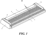
- FIG. 1 is a perspective view of a razor cartridge 100 according to an embodiment of the present invention.
- Each of a plurality of razor blades 10 may have a tip edge at one end thereof, and the other end thereof may be seated in a seating slot provided in a blade housing 8.
- the plurality of razor blades 10 includes one or more blades arranged in series in a shaving direction.
- the shaving direction refers to the direction from a front guard 2 to a rear cap 4.
- a pair of fixing clips 7a and 7b for fixing both ends of the blades 10 to the blade housing 8 may be provided.
- the fixing clips 7a and 7b are bent against the lower surface of the blade housing 8 and routed through the through holes formed near both ends of the blade housing 8, and wrapped around the ends of the blades 10.
- front legs of the fixing clips 7a and 7b are arranged through the through holes formed in the vicinity of the front end of the blade housing 8 and the rear legs of the fixing clips 7a and 7b wrap around the rear end of the blade housing 8.
- the present invention is not limited to this configuration.
- both the front and rear ends may be wrapped around the blade housing, or the legs of both fixing clips may be routed through front and rear through holes and bent against the lower surface of the blade housing.
- the plurality of razor blades 10 arranged in the blade housing 8 are flanked by the front guard 2 and the rear cap 4.
- An elastic member 1 may be arranged in front of the front guard 2 to be parallel to the blades 10 and a lubrication strip 3 may be arranged at the rear of the rear cap 4 to be parallel to the blades 10.
- the elastic member 1 erects the user's hair in a direction substantially perpendicular to the shaving direction to facilitate the cutting operation of the blades 10, and the lubrication strip 3 smooths rough skin after cutting.
- the present disclosure is not limited thereto.
- the lubrication strip 3 may be arranged in front of the front guard 2 to be parallel to the shaving blades 10, and the elastic member 1 may be arranged at the rear of the rear cap 4 to be parallel to the blades 10.
- lubrication strips 3 or elastic members 1 may be arranged in front of the front guard 2 and behind the rear cap 4.
- the plurality of blades 10 illustrated in FIG. 1 consist of five blades.
- the number of razor blades arranged in the razor cartridge 100 may be varied based on factors such as the shape and thickness of the blades 10, the span, the size of the razor cartridge, the purpose of shaving, and the like. Therefore, a greater or fewer number of razor blades may be arranged in the razor cartridge 100.
- the razor cartridge includes a front blade adjacent to the front guard 2 and a rear blade adjacent to the rear cap 4, and may further include additional blades between the front and rear blades.
- FIG. 2 is a sectional view of a central portion of the razor cartridge 100 of FIG. 1 , taken in a shaving direction.
- five blades 10a to 10e are respectively inserted in a corresponding gap (slot) formed between each of the seating projections 9a to 9e.
- a part of the edge portion or the bent portion of the front surface of the blades 10a to 10e may be supported by a seating projection (for example, seating projection 9a for blade 10a) in front thereof.
- the bases of the razor blades 10a to 10e may be supported between two seating projections (for example, seating projections 9a and 9b for blade 10a) located on the front and rear sides thereof.
- the razor blades 10a to 10e may be firmly installed in the blade housing 8 by a pair of fixing clips 7a and 7b, which press the tip edge of each blade downward at both ends thereof, while the blade is supported by the seating projections as described above.
- FIG. 1 or 2 A more detailed shape of embodiments of the blades 10 shown in FIG. 1 or 2 are described below with reference to FIGS. 3A and 3B .
- FIG. 3A is a side view of an integrated blade according to an embodiment of the present invention.
- an integrated blade 10 includes a base 13 seated in a slot of the blade housing 8, an edge portion 11 having a tip edge 15 at the front end thereof, and a bent portion 12 connecting the base 13 and the edge portion 11.
- the dimensions of the overall shape of the integrated blade include height h, depth d, radius of curvature R, and bending angle a.
- an embodiment of the integrated blade 10 may have a height h in a range of 1.5 mm to 5.0 mm, a depth d in a range of 0.7 mm to 3.0 mm, a radius of curvature R in a range of 0.45 mm to 0.9 mm, and a bending angle ⁇ in a range of 90° to 170°.
- the integrated blade 10 may be manufactured in a process of bending a single body and may be designed to be as thick or as thin as needed. Accordingly, a plane corresponding to the edge portion 11 is not aligned with a plane corresponding to the base 13 as the blade is curved.
- the blade used in the present invention may be a joined blade 40 as shown in FIG. 3B .
- the joined blade 40 consists of two members including a metal base 43 seated in a slot of the blade housing 8 and an edge portion 41 coupled to the metal base 43 and having a tip edge 15.
- the joined blade 40 has a base and a bent portion, and also has a blade attachment portion for supporting and joining the edge portion 41.
- the metal base 43 of the joined blade 40 may be formed thicker than or equal to the edge portion 41, and may thus firmly support the edge portion 41. Accordingly, the plane corresponding to the edge portion 41 is not aligned with a plane corresponding to the metal base 43 as the blade is curved.
- the blade according to the present invention is assumed to be the integrated blade 10 as shown in FIG. 3A .
- the present invention is not limited thereto.
- the present invention does not exclude a case where the blade is the joined blade 40 shown in FIG. 3B , a straight blade, or a blade having other shapes.
- using the integrated blade 10 or the joined blade 40 may be more appropriate than using the straight blade because the angle formed by the integrated blade 10 or the joined blade 40 with the skin is more favorable to shaving and less irritating to the skin.
- FIG. 4 is a longitudinal sectional view of a tip edge 15 formed on a razor blade 10, 40 according to an embodiment of the present invention.
- the tip edge 15 may include a substrate 16, an intermediate coating layer 18, and an outer coating layer 17, which are arranged from the innermost side in order.
- the substrate 16 is typically made of stainless steel, but other materials may be used.
- a hard coating layer may be further provided on the outer surface of the substrate to increase the strength and corrosion resistance of the substrate 16.
- the hard coating layer may be formed of a carbon-containing material such as diamond-like carbon (DLC), a nitride, an oxide, or a ceramic material.
- DLC diamond-like carbon
- the intermediate coating layer 18 formed between the substrate 16 and the outer coating layer 17 is used to increase the strength of the blades 10 and 40 or to promote adhesion of the outer coating layer 17 to the substrate 16.
- the intermediate coating layer 18 may be formed using a carbon-containing material such as DLC, a nitride, an oxide, a ceramic, or a chromium-containing material.
- the outer coating layer 17 is formed on the outer surface of the tip edge 15 to reduce friction.
- the outer coating layer 17 may be formed using polyfluorocarbon, such as polytetrafluoroethylene (PTFE), as a polymer composition.
- PTFE polytetrafluoroethylene
- PTFE acts as a nonflammable and stable dry lubricant composed of small particles that stably disperse.
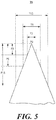
- FIG. 5 is a view showing a thickness dimension of the tip edge 15 shown in FIG. 4 at respective positions.
- the ultimate tip position of the tip edge 15 may be denoted by P0, where distances from the ultimate tip P0 are indicated by (i) expressed in micrometers ( ⁇ m), where each point located at each distance (i) from P0 is indicated by Pi.
- P3, P9, and P15 indicate positions which are located 3 ⁇ m, 9 ⁇ m, and 15 ⁇ m from the ultimate tip position P0, respectively.
- the thickness of the blade at each of these positions is defined in a transverse dimension of the tip edge 15.
- T15 means the transverse dimension (thickness) of the tip edge 15 at position of P15.
- the properties of the desired blade may be determined by designing various thickness profiles.
- a relatively thin blade and a relatively thick blade may be arranged together in the blade housing 8.
- the thin blade refers to a razor blade that has a relatively small thickness dimension compared to the thick blade at overall positions on the tip edge 15 and is thin and sharp as a whole compared to the thick blade while having low cutting force (cutting resistance) and low durability.
- the thick blade refers to a blade that has a relatively large thickness dimension compared to the thin blade at overall positions on the tip edge 15 and is thick and less sharp as a whole compared to the thin blade while having high cutting force (cutting resistance) and high durability.
- the thickness profile of the tip edge for each of the thin blade and the thick blade may be designed as shown in Table 1 below.
- Table 1 Thick blade Thin blade T3 1.2-1.6 ⁇ m 1.0-1.5 ⁇ m T9 3.6-4.4 ⁇ m 3.0-3.8 ⁇ m T15 5.7-6.7 ⁇ m 4.7-5.7 ⁇ m
- the thick blade generally has a greater thickness along the tip edge 15 than the thin blade, for example at positions located greater than 1 ⁇ m (PI) from the tip edge.
- PI 1 ⁇ m
- the profiles of the thick blade and the thin blade may be defined with a thickness dimension at position of Pi, and in some cases the important positions affecting change in the overall properties of the blade according to the thickness of the tip edge may be identified as P3, P9 and P15.
- P3, P9 and P15 the important positions affecting change in the overall properties of the blade according to the thickness of the tip edge.
- Such profile of a blade has a direct influence on the cutting force.
- the thin blade has a Shaving Hair Cutting Force (SHCF)(%) lower than the SHCF of the thick blade by a value of at least 5%, preferably about 9.36%.
- SHCF is an index for evaluating the cutting force known by those in the industry and indicates a relative value obtained by evaluating the force (gf) applied in cutting a hair strand. Therefore, SHCF is proportional to cutting force. In general, SHCF is indicated by "-" when the cutting force is small, and indicated by "+” when the cutting force is large. When the difference in SHCF is -5% or lower, it is determined that the shaving performance has been improved.
- the shape and thickness of the thin blade and the thick blade arranged in the razor cartridge 100 primarily affect shaving performance.
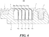
- FIG. 6 is a view showing spans S a to S e for respective blades with the fixing clips 7a and 7b removed from the razor cartridge 100 of FIG. 2 .
- the spans may be designed differently for respective specific blades.
- a span for a particular blade may be defined as a horizontal distance between the tip edge 15 of a preceding blade and the tip edge 15 of the particular blade.
- the span is defined as a distance between the wall of the front guard 2 or other preceding non-blade member and the tip edge 15 of the first blade 10a or other particular blade without a preceding blade.
- the span when the span is wide, it is advantageous for discharging a shaving aid, moisture or shaving debris, but it leads to increase in size of the razor cartridge and easily causes cuts during shaving.
- the span When the span is narrow, opposite effects are obtained. Therefore, it is important to select an appropriate span considering the shaving conditions, and the span also needs to be designed in accordance with the thickness of the blade.
- the thin blade may be designed to have a relatively narrow span in order to reduce cuts of the skin
- the thick blade may be designed to have a relatively wide span in order to improve the discharge performance at the time of shaving.
- the thick blade even if the thick blade has the same span as the thin blade, it may narrow the spacing between the preceding blades due to its own dimensions, and thus, the corresponding span needs to be widened.
- the thick blade is less sharp, has higher cutting force (cutting resistance) and durability. Accordingly, the thick blade is less worn and less likely to cause cuts or scratches on the skin even if the span becomes wider. Therefore, thick blades are more advantageous than thin blades in securing a wider span.
- the blades 10a to 10e arranged in FIG. 6 include at least one thin blade and/or at least one thick blade.
- the foremost blade 10a may be a thin blade and the rearmost blade 10e may be a thick blade. Since the foremost blade 10a is first brought into contact with the hairs during shaving, a thin razor blade having a low cutting force is arranged as the foremost blade. Since the rearmost blade 10e is the last blade that is brought into contact with the hairs, a thick blade having a high cutting force is arranged as the rearmost blade.
- the cutting force is conceptually the same as frictional resistance, such as SHCF described above, used in cutting hairs.
- the above-described arrangement is merely an embodiment of the present invention, and any other arrangement of the blades is also possible.
- the thick blade may be defined as thicker than the thin blade in the overall area as suggested in Table 1 above, but the thick blade and the thin blade may be divided by a single reference of T15.
- T15 for the thin blade may be in the range of 5.2 ⁇ 0.5 ⁇ m
- T15 for the thick blade may be in the range of 6.2 ⁇ 0.5 ⁇ m.
- the thickness ratio of the thick blade to the thin blade based on T15 is approximately 1.0 to 1.5, preferably 1.15 to 1.5.
- T15 The reason for using T15 as a reference is that the cutting force and durability of the blade are most influenced by the value of T15 and the portions below P15 on the tip edge 15 are most involved in cutting.
- the span for the thick blade may be designed to be wider than the span for the thin blade.
- a thinner tip edge has a lower cutting force (cutting resistance), but may cause skin irritation. Therefore, it is necessary to reduce the skin irritation by narrowing the span.
- a thicker tip edge is less likely to cause such skin irritation and has higher durability, and thus, may endure a larger load. Accordingly, by relatively increasing the span, the service life of the razor cartridge may be increased and discharge of shaving substances may be facilitated.
- the thick blade may be designed to have a wider span than a specific reference value and the thin blade may be designed to have a narrow span, based on a specific reference value (neutral value).
- the reference value may be set in various ranges, but may be selected in a range of 0.8 to 1.1 mm.
- the reference value may be about 0.95 mm.
- the narrow span for the thin blade is less than 0.95 mm, and the wide span for the thick blade is greater than 0.95 mm.
- the narrow span may be limited to 0.5 mm or more, and the large span may be limited to less than 1.6 mm.
- design of the razor cartridge considering both the thickness and the span of the razor blades at the same time contributes to ensuring sufficient shaving performance while minimizing skin irritation, as well as to improving the durability and service life of the entire razor cartridge.
- Equation 1 represents the relationship between the thicknesses of the thick blade and the thin blade at position P15. This equation is determined only by the shape of the blades regardless of the span.
- T 15 B ⁇ + 1 ⁇ T 15 A , 0.1 ⁇ ⁇ ⁇ 0.5
- T15 A denotes T15 of the thin blade and T15 B denotes T15 of the thick blade.
- T15 denotes T15 ( ⁇ m) of the thin blade
- x denotes the span (mm) of the thin blade.
- the span has a margin of ⁇ 10%. That is, x may have a range of 0.9*span to 1.1*span.
- the value of T15 of an actual product may not always satisfy Equation 2 and may have a value close to Equation 2.
- T15 denotes T15 ( ⁇ m) of the thick blade
- x denotes the span of the thick blade (mm).
- the span has a margin of ⁇ 10%. That is, x may have a range of 0.9*span to 1.1*span.
- the value of T15 of the actual product may not always satisfy Equation 3 and may have a value close to Equation 3.
- FIGS. 7 to 12 Various embodiments relating to blade arrangement, taking into account the correlation between the thickness and the span of the blades as described above, are shown in FIGS. 7 to 12 .
- the thin blade may be defined as a blade with T15 of 5.2 ⁇ 0.5 ⁇ m
- the thick blade may be defined as a blade with T15 of 6.2 ⁇ 0.5 ⁇ m.
- FIG. 7 is a view showing an embodiment in which spans gradually increase among the blades.
- the spans S a to S e of the blades 10a to 10e from the front to back of the razor cartridge gradually increase from the foremost blade 10a to the rearmost blade 10e.
- thin blades arranged at the front of the razor cartridge may allow for adequate shaving with low cutting resistance while reducing skin irritation, and thick blades arranged behind may ensure sufficient support stiffness and smooth discharge of shaving substances.
- shallow shaving is performed by the front blades, followed by deep shaving by the rear blades. Thereby, a balanced shaving stroke may be provided.
- FIG. 7 illustrates that three identical thin blades 20 are arranged at the front and two thick blades 30 are arranged at the rear
- the present invention is not limited thereto.
- five different razor blades may be arranged such that the thickness thereof gradually increases from the front to the back, the relative number of thin blades to thick blades may differ, or the positioning of thin blades and thick blades may also differ.
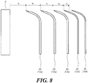
- FIG. 8 is a view showing an embodiment in which spans gradually decreases among the blades.
- the spans S a to S e of the blades 10a to 10e arranged from the front to back of the razor cartridge gradually decrease from the foremost blade 10a to the rearmost blade 10e.
- the blades arranged at the front of the razor cartridge may ensure sufficient support stiffness and smooth discharge of shaving substances, and the blades arranged behind may provide proper shaving with low cutting resistance while reducing skin irritation.
- the front blades may perform shaving with high cutting force, and then the rear blades may finish shaving, making the skin clean and smooth.
- FIG. 8 illustrates that three identical thick blades 30 are arranged at the front and two thin blades 20 are arranged at the rear
- the present invention is not limited thereto.
- five different razor blades may be arranged such that the thickness thereof gradually decreases from the front to the back.
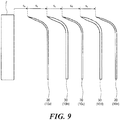
- FIGS. 9 and 10 are views showing an embodiment in which spans of the blades are formed in an alternating pattern.
- thin and thick blades 20 and 30 are alternately arranged from the front to the back of the razor cartridge, and the spans therefor are provided such that a wide span and a narrow span are alternately arranged.
- a thin blade 20 is arranged first at the front.
- a thick blade 30 is arranged first at the front.
- the spans for the thick blades are wide spans and the spans for the thin blades are narrow spans.
- the shaving characteristics of the thick blades and the shaving characteristics of the thin blades complement each other, and thus, the overall shaving performance may be improved.
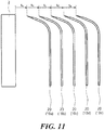
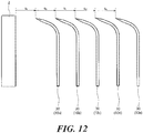
- FIGS. 11 and 12 illustrate a case where spans of all blades are narrow spans or wide spans.
- the blades are all thin blades and the spans therefor are narrow spans.
- Such thin blades having narrow spans reduce skin irritation and enables shaving with low cutting resistance. While it is illustrated in the figure that the thin blades have the same thickness and the same span, the present invention is not limited thereto. For example, when the thin blades have different thicknesses, the blades may have different spans.
- FIG. 12 illustrates a case where the blades are all thick blades and have wide spans.
- the thick blades having wide spans provide increased durability and smooth discharge of shaving substances along with larger cutting force in shaving. While it is illustrated in the figure that the thick blades have the same thickness and the same span, the present invention is not limited thereto. For example, when the thick blades have different thicknesses, the blades may have different spans.
- the span and the thickness T15 of the five blades may be selected so as to satisfy the numerical range of at least one of the above-described Equations 1 to 3.
- the number of razor blades is not limited to five, but may be reduced or increased from five.
- the razor cartridge 100 in which the blades 10 are arranged between the front guard 2 at the front and the rear cap 4 at the rear has been described.
- the razor cartridge 110 may be provided with an additional guards or members (intermediate guard, third contact member, and the like) between the front guard 2 and the rear cap 4.
- an intermediate guard is additionally formed in the middle of the razor cartridge 110, or other non-middle position in the cartridge, shaving safety may be enhanced along with decrease in nicks and cuts, and close contact with the skin may also be enhanced.
- different contact planes are provided in the front area formed between the front guard 2 and the intermediate guard and in the rear region formed between the intermediate guard and the rear cap 4, respectively, shaving with a variety of complex characteristics can be performed.
- FIG. 13 is a cross-sectional view showing a razor cartridge 110 according to another embodiment of the present invention.
- four blades 10a to 10d are arranged in the blade housing 8, and an intermediate guard 5 is provided between two blades 10a and 10b in the front area and two blades 10c and 10b in the rear area.
- the intermediate guard 5 may be mounted between the seating projections in a similar manner to mounting of the blades 10a to 10d.
- the present invention is not limited thereto.
- the intermediate guard may be provided in the form of a partition wall integrated with the blade housing 8.
- the blades 10a and 10b arranged between the front guard 2 and the intermediate guard 5 are relatively thin blades (e.g., blades having T15 of 5.2 ⁇ 0.5 ⁇ m), and the blades 10c and lOd arranged between the intermediate guard 5 and the rear cap 4 are relatively thick blades (e.g., blades having T15 of 6.2 ⁇ 0.5 ⁇ m).
- the thin blades 10a and 10b in the front area have relatively narrow spans
- the thick blades 10c and 10d in the rear area have relatively wide spans.
- the spans S a and S b of the thin blades 10a and 10b are less than a reference value (e.g., 095 mm), and the spans S c and S d of the thick blades 10c and 10d are greater than the reference value.
- a reference value e.g. 095 mm
- the thin blades in the front area may provide proper shaving with low cutting resistance while reducing skin irritation, and the thick blades 10c and 10d arranged behind may ensure sufficient support stiffness and durability.
- the blades arranged in at least one of the front area and the rear area includes a thin blade having a first span (e.g., a blade with T15 of 5.2 ⁇ 0.5 ⁇ m), and a thick blade having a span wider than the first span (e.g., a blade with T15 of 6.2 ⁇ 0.5 ⁇ m).
- the blades 10a and 10b in the front area may be arranged in order of a thin blade followed by a thick blade (or vice versa )
- the blades 10c and 10d in the rear area may be arranged in order of a thin blade followed by a thick blade (or vice versa ).
- the spans and thicknesses of the four blades at T15 may be selected so as to satisfy the numerical range of at least one of the above-mentioned Equations 1 to 3.
- the number of razor blades is not limited to four. Therefore, the number of blades in the front area and the number of blades in the rear area may be equally one or three or more. Alternatively, the number of blades in the front area may be different from the number of blades in the rear area.
- FIG. 14 is a view showing a positional relationship between the contact plane cp of the razor cartridge and each of the tip edges of the blades.
- the contact plane cp is a virtual plane defined by connecting the upper end of a first contact member located in front of the blades and the upper end of a second contact member located behind the blades.
- the contact plane cp is shown as a line in a cross-sectional view of FIG. 14 .
- the exposure of a blade is a relative value indicating the position of the tip edge of the blade with respect to the contact plane, and may be divided into three types, i.e., positive, neutral and negative.
- the exposure of the thick blade may be designed to be larger than the exposure of the thin blade.
- the blades may be designed such that the thick blade has a positive exposure and the thin blade has a negative exposure.
- the cutting force the cutting resistance
- skin irritation may be caused. Therefore, it is necessary to reduce skin irritation while making the cutting work easier by relatively reducing the exposure.
- the tip edge if the tip edge is thick, it may have high durability, and thus, may withstand a larger load. Accordingly, the cutting effectiveness and service life of the razor cartridge may be increased by relatively increasing the exposure.
- a relatively thin blade is arranged at a position where the span is less than a reference value and a relatively thick blade is arranged at a position where the span is greater than the reference value.
- the thick blade which is arranged at a position having a large span, may secure sufficient cutting force and increase the service life and durability of the razor cartridge.
Landscapes
- Life Sciences & Earth Sciences (AREA)
- Forests & Forestry (AREA)
- Engineering & Computer Science (AREA)
- Mechanical Engineering (AREA)
- Physics & Mathematics (AREA)
- Geometry (AREA)
- Dry Shavers And Clippers (AREA)
Applications Claiming Priority (1)
| Application Number | Priority Date | Filing Date | Title |
|---|---|---|---|
| KR1020180087848A KR102106304B1 (ko) | 2018-07-27 | 2018-07-27 | 면도기 카트리지 |
Publications (2)
| Publication Number | Publication Date |
|---|---|
| EP3610999A1 EP3610999A1 (en) | 2020-02-19 |
| EP3610999B1 true EP3610999B1 (en) | 2021-02-17 |
Family
ID=67438856
Family Applications (1)
| Application Number | Title | Priority Date | Filing Date |
|---|---|---|---|
| EP19188288.5A Active EP3610999B1 (en) | 2018-07-27 | 2019-07-25 | Razor cartridge |
Country Status (5)
| Country | Link |
|---|---|
| US (1) | US10960559B2 (https=) |
| EP (1) | EP3610999B1 (https=) |
| JP (1) | JP7395266B2 (https=) |
| KR (1) | KR102106304B1 (https=) |
| CN (1) | CN110774321B (https=) |
Families Citing this family (15)
| Publication number | Priority date | Publication date | Assignee | Title |
|---|---|---|---|---|
| KR102106304B1 (ko) * | 2018-07-27 | 2020-05-04 | 주식회사 도루코 | 면도기 카트리지 |
| EP3689560A1 (en) | 2019-01-31 | 2020-08-05 | Bic Violex S.A. | Shaving head with increased inter blade span |
| PL3917730T3 (pl) * | 2019-01-31 | 2024-11-04 | BIC Violex Single Member S.A. | Wkład golarki |
| KR102211395B1 (ko) * | 2019-05-22 | 2021-02-03 | 주식회사 도루코 | 면도날 및 면도날 제조방법 |
| CN114080306B (zh) * | 2019-07-31 | 2024-03-29 | 吉列有限责任公司 | 剃刀和剃刀刀片架 |
| EP4003676A1 (en) | 2019-07-31 | 2022-06-01 | The Gillette Company LLC | Razors and razor cartridges with colored blades |
| KR102343058B1 (ko) * | 2019-12-10 | 2021-12-24 | 주식회사 도루코 | 면도기 카트리지 |
| EP4321313A3 (en) | 2020-02-12 | 2024-05-08 | Edgewell Personal Care Brands, LLC | Razor cartridge |
| EP4304820A1 (en) * | 2021-03-12 | 2024-01-17 | Edgewell Personal Care Brands, LLC | Razor cartridge |
| KR102821256B1 (ko) * | 2021-11-30 | 2025-06-17 | 주식회사 도루코 | 면도기 카트리지 |
| USD1107313S1 (en) | 2024-04-23 | 2025-12-23 | The Gillette Company Llc | Shaving razor cartridge |
| US20250381689A1 (en) * | 2024-06-18 | 2025-12-18 | The Gillette Company Llc | Shaving razor cartridge |
| US20250381691A1 (en) * | 2024-06-18 | 2025-12-18 | The Gillette Company Llc | Shaving razor cartridge |
| US20250381692A1 (en) * | 2024-06-18 | 2025-12-18 | The Gillette Company Llc | Shaving razor cartridge |
| US20250381693A1 (en) * | 2024-06-18 | 2025-12-18 | The Gillette Company Llc | Shaving razor cartridge |
Family Cites Families (30)
| Publication number | Priority date | Publication date | Assignee | Title |
|---|---|---|---|---|
| US4031620A (en) * | 1972-07-25 | 1977-06-28 | The Gillette Company | Shaving system |
| DE69233787D1 (de) | 1991-11-27 | 2010-07-15 | Gillette Co | Rasierapparate |
| US6212777B1 (en) * | 1993-09-29 | 2001-04-10 | The Gillette Company | Safety razors |
| GB9320058D0 (en) * | 1993-09-29 | 1993-11-17 | Gillette Co | Savety razors |
| BR9509216A (pt) | 1994-10-03 | 1998-01-27 | Gillette Co | Conjunto de lâmina para aparelho para barbear |
| US6516518B1 (en) | 1996-01-12 | 2003-02-11 | The Gillette Company | Razor blade unit |
| US5956851A (en) | 1996-04-10 | 1999-09-28 | The Gillette Company | Shaving system including handle and replaceable cartridges |
| US6041926A (en) | 1996-04-10 | 2000-03-28 | The Gillette Company | Dispensing razor blade cartridges used with a handle |
| US5687485A (en) | 1996-05-15 | 1997-11-18 | The Gillette Company | Razor handle |
| JP3213693B2 (ja) * | 1996-05-21 | 2001-10-02 | 株式会社貝印刃物開発センター | 三枚刃剃刀における刃先構造 |
| US5956848A (en) | 1997-02-27 | 1999-09-28 | The Gillette Company | Shaving system |
| DE69806026T2 (de) * | 1997-09-18 | 2002-10-31 | The Gillette Co., Boston | Sicherheitsrasierer |
| GB2354474B8 (en) * | 1999-09-27 | 2008-01-29 | Gillette Co | Safety razors |
| US6684513B1 (en) | 2000-02-29 | 2004-02-03 | The Gillette Company | Razor blade technology |
| KR101123162B1 (ko) * | 2003-06-26 | 2012-03-19 | 코닌클리케 필립스 일렉트로닉스 엔.브이. | 구부러진 면도기 날과 이러한 면도기 날의 제조 |
| US7690122B2 (en) * | 2004-03-11 | 2010-04-06 | The Gillette Company | Shaving razor with button |
| US20110023307A1 (en) * | 2005-06-10 | 2011-02-03 | Eveready Battery Company, Inc. | Inter-Blade Guard and Method for Manufacturing Same |
| US8438736B2 (en) * | 2007-08-24 | 2013-05-14 | The Gillette Company | Safety razor with improved guard |
| US9248579B2 (en) * | 2008-07-16 | 2016-02-02 | The Gillette Company | Razors and razor cartridges |
| WO2011075505A1 (en) | 2009-12-18 | 2011-06-23 | The Gillette Company | Razor cartridge with non-cutting element |
| EP2450162A1 (en) | 2010-11-04 | 2012-05-09 | The Gillette Company | Razor cartridge |
| US20140026424A1 (en) * | 2012-07-24 | 2014-01-30 | The Gillette Company | Razor cartridge |
| EP2823942A1 (en) * | 2013-07-10 | 2015-01-14 | The Gillette Company | Razor cartridges |
| WO2016032014A1 (ko) * | 2014-08-25 | 2016-03-03 | 주식회사 도루코 | 면도날 및 이를 적용한 면도기 카트리지 |
| BR112017010922B1 (pt) | 2014-12-22 | 2021-07-06 | Bic-Violex Sa | Lâmina para barbeamento e depilação |
| US10773404B2 (en) * | 2015-05-13 | 2020-09-15 | The Gillette Company Llc | Shaving razor cartridge |
| KR101718767B1 (ko) * | 2017-02-23 | 2017-03-22 | 주식회사 도루코 | 면도기 카트리지 및 이를 이용한 면도기 |
| CN208246877U (zh) * | 2017-08-25 | 2018-12-18 | 宁波开利控股集团股份有限公司 | 一种矩阵式排列的漏须刀头 |
| KR102063770B1 (ko) * | 2018-07-27 | 2020-01-08 | 주식회사 도루코 | 면도기 카트리지 |
| KR102106304B1 (ko) * | 2018-07-27 | 2020-05-04 | 주식회사 도루코 | 면도기 카트리지 |
-
2018
- 2018-07-27 KR KR1020180087848A patent/KR102106304B1/ko active Active
-
2019
- 2019-06-12 CN CN201910504115.7A patent/CN110774321B/zh active Active
- 2019-06-18 JP JP2019113015A patent/JP7395266B2/ja active Active
- 2019-07-12 US US16/510,492 patent/US10960559B2/en active Active
- 2019-07-25 EP EP19188288.5A patent/EP3610999B1/en active Active
Non-Patent Citations (1)
| Title |
|---|
| None * |
Also Published As
| Publication number | Publication date |
|---|---|
| JP2020014837A (ja) | 2020-01-30 |
| US10960559B2 (en) | 2021-03-30 |
| US20200031006A1 (en) | 2020-01-30 |
| CN110774321B (zh) | 2021-09-10 |
| CN110774321A (zh) | 2020-02-11 |
| KR20200012489A (ko) | 2020-02-05 |
| EP3610999A1 (en) | 2020-02-19 |
| KR102106304B1 (ko) | 2020-05-04 |
| JP7395266B2 (ja) | 2023-12-11 |
Similar Documents
| Publication | Publication Date | Title |
|---|---|---|
| EP3610999B1 (en) | Razor cartridge | |
| EP3599066B1 (en) | Razor cartridge | |
| JP7583078B2 (ja) | 剃毛かみそりカートリッジ | |
| AU2005231790B2 (en) | Razor cartridge | |
| AU2005222584B2 (en) | Shaving razors with multiple blades | |
| JP6239134B2 (ja) | かみそりの刃及びこれを適用したかみそりカートリッジ | |
| JP7675651B2 (ja) | かみそりカートリッジ | |
| EP2823942A1 (en) | Razor cartridges | |
| US20100218381A1 (en) | Inter-Blade Guard and Method For Manufacturing Same | |
| US11691306B2 (en) | Razor cartridge | |
| US10780598B2 (en) | Razor cartridge and razor using same | |
| US20220314476A1 (en) | Razor cartridge | |
| US12172331B2 (en) | Razor cartridge | |
| US20110023307A1 (en) | Inter-Blade Guard and Method for Manufacturing Same | |
| KR20080056742A (ko) | 면도날 유닛 | |
| KR20220056102A (ko) | 비대칭 면도날 | |
| JP3127778U (ja) | 長刃かみそり用剃刀刃 |
Legal Events
| Date | Code | Title | Description |
|---|---|---|---|
| PUAI | Public reference made under article 153(3) epc to a published international application that has entered the european phase |
Free format text: ORIGINAL CODE: 0009012 |
|
| STAA | Information on the status of an ep patent application or granted ep patent |
Free format text: STATUS: THE APPLICATION HAS BEEN PUBLISHED |
|
| AK | Designated contracting states |
Kind code of ref document: A1 Designated state(s): AL AT BE BG CH CY CZ DE DK EE ES FI FR GB GR HR HU IE IS IT LI LT LU LV MC MK MT NL NO PL PT RO RS SE SI SK SM TR |
|
| AX | Request for extension of the european patent |
Extension state: BA ME |
|
| STAA | Information on the status of an ep patent application or granted ep patent |
Free format text: STATUS: REQUEST FOR EXAMINATION WAS MADE |
|
| 17P | Request for examination filed |
Effective date: 20200309 |
|
| RBV | Designated contracting states (corrected) |
Designated state(s): AL AT BE BG CH CY CZ DE DK EE ES FI FR GB GR HR HU IE IS IT LI LT LU LV MC MK MT NL NO PL PT RO RS SE SI SK SM TR |
|
| RIC1 | Information provided on ipc code assigned before grant |
Ipc: B26B 21/40 20060101AFI20200807BHEP |
|
| GRAP | Despatch of communication of intention to grant a patent |
Free format text: ORIGINAL CODE: EPIDOSNIGR1 |
|
| STAA | Information on the status of an ep patent application or granted ep patent |
Free format text: STATUS: GRANT OF PATENT IS INTENDED |
|
| INTG | Intention to grant announced |
Effective date: 20200929 |
|
| GRAS | Grant fee paid |
Free format text: ORIGINAL CODE: EPIDOSNIGR3 |
|
| GRAA | (expected) grant |
Free format text: ORIGINAL CODE: 0009210 |
|
| STAA | Information on the status of an ep patent application or granted ep patent |
Free format text: STATUS: THE PATENT HAS BEEN GRANTED |
|
| AK | Designated contracting states |
Kind code of ref document: B1 Designated state(s): AL AT BE BG CH CY CZ DE DK EE ES FI FR GB GR HR HU IE IS IT LI LT LU LV MC MK MT NL NO PL PT RO RS SE SI SK SM TR |
|
| REG | Reference to a national code |
Ref country code: GB Ref legal event code: FG4D |
|
| REG | Reference to a national code |
Ref country code: CH Ref legal event code: EP |
|
| REG | Reference to a national code |
Ref country code: DE Ref legal event code: R096 Ref document number: 602019002568 Country of ref document: DE |
|
| REG | Reference to a national code |
Ref country code: AT Ref legal event code: REF Ref document number: 1360880 Country of ref document: AT Kind code of ref document: T Effective date: 20210315 |
|
| REG | Reference to a national code |
Ref country code: IE Ref legal event code: FG4D |
|
| REG | Reference to a national code |
Ref country code: LT Ref legal event code: MG9D |
|
| REG | Reference to a national code |
Ref country code: NL Ref legal event code: MP Effective date: 20210217 |
|
| PG25 | Lapsed in a contracting state [announced via postgrant information from national office to epo] |
Ref country code: FI Free format text: LAPSE BECAUSE OF FAILURE TO SUBMIT A TRANSLATION OF THE DESCRIPTION OR TO PAY THE FEE WITHIN THE PRESCRIBED TIME-LIMIT Effective date: 20210217 Ref country code: GR Free format text: LAPSE BECAUSE OF FAILURE TO SUBMIT A TRANSLATION OF THE DESCRIPTION OR TO PAY THE FEE WITHIN THE PRESCRIBED TIME-LIMIT Effective date: 20210518 Ref country code: HR Free format text: LAPSE BECAUSE OF FAILURE TO SUBMIT A TRANSLATION OF THE DESCRIPTION OR TO PAY THE FEE WITHIN THE PRESCRIBED TIME-LIMIT Effective date: 20210217 Ref country code: BG Free format text: LAPSE BECAUSE OF FAILURE TO SUBMIT A TRANSLATION OF THE DESCRIPTION OR TO PAY THE FEE WITHIN THE PRESCRIBED TIME-LIMIT Effective date: 20210517 Ref country code: NO Free format text: LAPSE BECAUSE OF FAILURE TO SUBMIT A TRANSLATION OF THE DESCRIPTION OR TO PAY THE FEE WITHIN THE PRESCRIBED TIME-LIMIT Effective date: 20210517 Ref country code: PT Free format text: LAPSE BECAUSE OF FAILURE TO SUBMIT A TRANSLATION OF THE DESCRIPTION OR TO PAY THE FEE WITHIN THE PRESCRIBED TIME-LIMIT Effective date: 20210617 Ref country code: LT Free format text: LAPSE BECAUSE OF FAILURE TO SUBMIT A TRANSLATION OF THE DESCRIPTION OR TO PAY THE FEE WITHIN THE PRESCRIBED TIME-LIMIT Effective date: 20210217 |
|
| REG | Reference to a national code |
Ref country code: AT Ref legal event code: MK05 Ref document number: 1360880 Country of ref document: AT Kind code of ref document: T Effective date: 20210217 |
|
| PG25 | Lapsed in a contracting state [announced via postgrant information from national office to epo] |
Ref country code: SE Free format text: LAPSE BECAUSE OF FAILURE TO SUBMIT A TRANSLATION OF THE DESCRIPTION OR TO PAY THE FEE WITHIN THE PRESCRIBED TIME-LIMIT Effective date: 20210217 Ref country code: RS Free format text: LAPSE BECAUSE OF FAILURE TO SUBMIT A TRANSLATION OF THE DESCRIPTION OR TO PAY THE FEE WITHIN THE PRESCRIBED TIME-LIMIT Effective date: 20210217 Ref country code: PL Free format text: LAPSE BECAUSE OF FAILURE TO SUBMIT A TRANSLATION OF THE DESCRIPTION OR TO PAY THE FEE WITHIN THE PRESCRIBED TIME-LIMIT Effective date: 20210217 Ref country code: NL Free format text: LAPSE BECAUSE OF FAILURE TO SUBMIT A TRANSLATION OF THE DESCRIPTION OR TO PAY THE FEE WITHIN THE PRESCRIBED TIME-LIMIT Effective date: 20210217 Ref country code: LV Free format text: LAPSE BECAUSE OF FAILURE TO SUBMIT A TRANSLATION OF THE DESCRIPTION OR TO PAY THE FEE WITHIN THE PRESCRIBED TIME-LIMIT Effective date: 20210217 |
|
| PG25 | Lapsed in a contracting state [announced via postgrant information from national office to epo] |
Ref country code: IS Free format text: LAPSE BECAUSE OF FAILURE TO SUBMIT A TRANSLATION OF THE DESCRIPTION OR TO PAY THE FEE WITHIN THE PRESCRIBED TIME-LIMIT Effective date: 20210617 |
|
| PG25 | Lapsed in a contracting state [announced via postgrant information from national office to epo] |
Ref country code: CZ Free format text: LAPSE BECAUSE OF FAILURE TO SUBMIT A TRANSLATION OF THE DESCRIPTION OR TO PAY THE FEE WITHIN THE PRESCRIBED TIME-LIMIT Effective date: 20210217 Ref country code: EE Free format text: LAPSE BECAUSE OF FAILURE TO SUBMIT A TRANSLATION OF THE DESCRIPTION OR TO PAY THE FEE WITHIN THE PRESCRIBED TIME-LIMIT Effective date: 20210217 Ref country code: SM Free format text: LAPSE BECAUSE OF FAILURE TO SUBMIT A TRANSLATION OF THE DESCRIPTION OR TO PAY THE FEE WITHIN THE PRESCRIBED TIME-LIMIT Effective date: 20210217 Ref country code: AT Free format text: LAPSE BECAUSE OF FAILURE TO SUBMIT A TRANSLATION OF THE DESCRIPTION OR TO PAY THE FEE WITHIN THE PRESCRIBED TIME-LIMIT Effective date: 20210217 |
|
| REG | Reference to a national code |
Ref country code: DE Ref legal event code: R097 Ref document number: 602019002568 Country of ref document: DE |
|
| PG25 | Lapsed in a contracting state [announced via postgrant information from national office to epo] |
Ref country code: DK Free format text: LAPSE BECAUSE OF FAILURE TO SUBMIT A TRANSLATION OF THE DESCRIPTION OR TO PAY THE FEE WITHIN THE PRESCRIBED TIME-LIMIT Effective date: 20210217 Ref country code: SK Free format text: LAPSE BECAUSE OF FAILURE TO SUBMIT A TRANSLATION OF THE DESCRIPTION OR TO PAY THE FEE WITHIN THE PRESCRIBED TIME-LIMIT Effective date: 20210217 Ref country code: RO Free format text: LAPSE BECAUSE OF FAILURE TO SUBMIT A TRANSLATION OF THE DESCRIPTION OR TO PAY THE FEE WITHIN THE PRESCRIBED TIME-LIMIT Effective date: 20210217 |
|
| PLBE | No opposition filed within time limit |
Free format text: ORIGINAL CODE: 0009261 |
|
| STAA | Information on the status of an ep patent application or granted ep patent |
Free format text: STATUS: NO OPPOSITION FILED WITHIN TIME LIMIT |
|
| 26N | No opposition filed |
Effective date: 20211118 |
|
| PG25 | Lapsed in a contracting state [announced via postgrant information from national office to epo] |
Ref country code: ES Free format text: LAPSE BECAUSE OF FAILURE TO SUBMIT A TRANSLATION OF THE DESCRIPTION OR TO PAY THE FEE WITHIN THE PRESCRIBED TIME-LIMIT Effective date: 20210217 Ref country code: AL Free format text: LAPSE BECAUSE OF FAILURE TO SUBMIT A TRANSLATION OF THE DESCRIPTION OR TO PAY THE FEE WITHIN THE PRESCRIBED TIME-LIMIT Effective date: 20210217 |
|
| PG25 | Lapsed in a contracting state [announced via postgrant information from national office to epo] |
Ref country code: SI Free format text: LAPSE BECAUSE OF FAILURE TO SUBMIT A TRANSLATION OF THE DESCRIPTION OR TO PAY THE FEE WITHIN THE PRESCRIBED TIME-LIMIT Effective date: 20210217 |
|
| PG25 | Lapsed in a contracting state [announced via postgrant information from national office to epo] |
Ref country code: MC Free format text: LAPSE BECAUSE OF FAILURE TO SUBMIT A TRANSLATION OF THE DESCRIPTION OR TO PAY THE FEE WITHIN THE PRESCRIBED TIME-LIMIT Effective date: 20210217 |
|
| REG | Reference to a national code |
Ref country code: BE Ref legal event code: MM Effective date: 20210731 |
|
| PG25 | Lapsed in a contracting state [announced via postgrant information from national office to epo] |
Ref country code: IT Free format text: LAPSE BECAUSE OF FAILURE TO SUBMIT A TRANSLATION OF THE DESCRIPTION OR TO PAY THE FEE WITHIN THE PRESCRIBED TIME-LIMIT Effective date: 20210217 |
|
| PG25 | Lapsed in a contracting state [announced via postgrant information from national office to epo] |
Ref country code: IS Free format text: LAPSE BECAUSE OF FAILURE TO SUBMIT A TRANSLATION OF THE DESCRIPTION OR TO PAY THE FEE WITHIN THE PRESCRIBED TIME-LIMIT Effective date: 20210617 Ref country code: LU Free format text: LAPSE BECAUSE OF NON-PAYMENT OF DUE FEES Effective date: 20210725 |
|
| PG25 | Lapsed in a contracting state [announced via postgrant information from national office to epo] |
Ref country code: IE Free format text: LAPSE BECAUSE OF NON-PAYMENT OF DUE FEES Effective date: 20210725 Ref country code: BE Free format text: LAPSE BECAUSE OF NON-PAYMENT OF DUE FEES Effective date: 20210731 |
|
| REG | Reference to a national code |
Ref country code: CH Ref legal event code: PL |
|
| PG25 | Lapsed in a contracting state [announced via postgrant information from national office to epo] |
Ref country code: LI Free format text: LAPSE BECAUSE OF NON-PAYMENT OF DUE FEES Effective date: 20220731 Ref country code: CH Free format text: LAPSE BECAUSE OF NON-PAYMENT OF DUE FEES Effective date: 20220731 |
|
| PG25 | Lapsed in a contracting state [announced via postgrant information from national office to epo] |
Ref country code: CY Free format text: LAPSE BECAUSE OF FAILURE TO SUBMIT A TRANSLATION OF THE DESCRIPTION OR TO PAY THE FEE WITHIN THE PRESCRIBED TIME-LIMIT Effective date: 20210217 |
|
| PG25 | Lapsed in a contracting state [announced via postgrant information from national office to epo] |
Ref country code: HU Free format text: LAPSE BECAUSE OF FAILURE TO SUBMIT A TRANSLATION OF THE DESCRIPTION OR TO PAY THE FEE WITHIN THE PRESCRIBED TIME-LIMIT; INVALID AB INITIO Effective date: 20190725 |
|
| PG25 | Lapsed in a contracting state [announced via postgrant information from national office to epo] |
Ref country code: MK Free format text: LAPSE BECAUSE OF FAILURE TO SUBMIT A TRANSLATION OF THE DESCRIPTION OR TO PAY THE FEE WITHIN THE PRESCRIBED TIME-LIMIT Effective date: 20210217 |
|
| PG25 | Lapsed in a contracting state [announced via postgrant information from national office to epo] |
Ref country code: TR Free format text: LAPSE BECAUSE OF FAILURE TO SUBMIT A TRANSLATION OF THE DESCRIPTION OR TO PAY THE FEE WITHIN THE PRESCRIBED TIME-LIMIT Effective date: 20210217 |
|
| PG25 | Lapsed in a contracting state [announced via postgrant information from national office to epo] |
Ref country code: MT Free format text: LAPSE BECAUSE OF FAILURE TO SUBMIT A TRANSLATION OF THE DESCRIPTION OR TO PAY THE FEE WITHIN THE PRESCRIBED TIME-LIMIT Effective date: 20210217 |
|
| PGFP | Annual fee paid to national office [announced via postgrant information from national office to epo] |
Ref country code: GB Payment date: 20250612 Year of fee payment: 7 |
|
| PGFP | Annual fee paid to national office [announced via postgrant information from national office to epo] |
Ref country code: FR Payment date: 20250623 Year of fee payment: 7 |
|
| PGFP | Annual fee paid to national office [announced via postgrant information from national office to epo] |
Ref country code: DE Payment date: 20250618 Year of fee payment: 7 |