EP3608466B1 - Wäschebehandlungsvorrichtung und verfahren zu deren betrieb - Google Patents
Wäschebehandlungsvorrichtung und verfahren zu deren betrieb Download PDFInfo
- Publication number
- EP3608466B1 EP3608466B1 EP18188263.0A EP18188263A EP3608466B1 EP 3608466 B1 EP3608466 B1 EP 3608466B1 EP 18188263 A EP18188263 A EP 18188263A EP 3608466 B1 EP3608466 B1 EP 3608466B1
- Authority
- EP
- European Patent Office
- Prior art keywords
- laundry
- drum
- protrusion
- shape
- drive current
- Prior art date
- Legal status (The legal status is an assumption and is not a legal conclusion. Google has not performed a legal analysis and makes no representation as to the accuracy of the status listed.)
- Active
Links
- 238000000034 method Methods 0.000 title claims description 33
- XLYOFNOQVPJJNP-UHFFFAOYSA-N water Substances O XLYOFNOQVPJJNP-UHFFFAOYSA-N 0.000 claims description 27
- 239000000835 fiber Substances 0.000 claims description 25
- 238000005406 washing Methods 0.000 claims description 25
- 230000006698 induction Effects 0.000 claims description 19
- 239000000463 material Substances 0.000 claims description 19
- 230000008569 process Effects 0.000 claims description 18
- 238000010438 heat treatment Methods 0.000 claims description 16
- 230000008859 change Effects 0.000 claims description 14
- 238000012545 processing Methods 0.000 claims description 14
- 238000012360 testing method Methods 0.000 claims description 7
- 230000001419 dependent effect Effects 0.000 claims description 6
- 238000010586 diagram Methods 0.000 claims description 3
- 230000003292 diminished effect Effects 0.000 claims description 2
- 239000003302 ferromagnetic material Substances 0.000 claims description 2
- 230000006399 behavior Effects 0.000 description 9
- 229920002994 synthetic fiber Polymers 0.000 description 6
- 229920001410 Microfiber Polymers 0.000 description 5
- 239000004744 fabric Substances 0.000 description 5
- 239000003658 microfiber Substances 0.000 description 5
- 229920000728 polyester Polymers 0.000 description 5
- 230000000875 corresponding effect Effects 0.000 description 4
- 230000000694 effects Effects 0.000 description 4
- 230000005484 gravity Effects 0.000 description 4
- 229920000742 Cotton Polymers 0.000 description 3
- 239000010865 sewage Substances 0.000 description 3
- 239000000654 additive Substances 0.000 description 2
- 238000001514 detection method Methods 0.000 description 2
- 238000002474 experimental method Methods 0.000 description 2
- 230000000630 rising effect Effects 0.000 description 2
- 229910001220 stainless steel Inorganic materials 0.000 description 2
- 239000010935 stainless steel Substances 0.000 description 2
- 239000012209 synthetic fiber Substances 0.000 description 2
- 229910000831 Steel Inorganic materials 0.000 description 1
- 230000009471 action Effects 0.000 description 1
- 230000003213 activating effect Effects 0.000 description 1
- 239000004411 aluminium Substances 0.000 description 1
- 229910052782 aluminium Inorganic materials 0.000 description 1
- XAGFODPZIPBFFR-UHFFFAOYSA-N aluminium Chemical compound [Al] XAGFODPZIPBFFR-UHFFFAOYSA-N 0.000 description 1
- 230000008901 benefit Effects 0.000 description 1
- 230000005540 biological transmission Effects 0.000 description 1
- 230000015572 biosynthetic process Effects 0.000 description 1
- 230000002596 correlated effect Effects 0.000 description 1
- 238000005260 corrosion Methods 0.000 description 1
- 230000007797 corrosion Effects 0.000 description 1
- 238000001035 drying Methods 0.000 description 1
- 230000007613 environmental effect Effects 0.000 description 1
- 230000006870 function Effects 0.000 description 1
- 230000010354 integration Effects 0.000 description 1
- 229910052751 metal Inorganic materials 0.000 description 1
- 239000002184 metal Substances 0.000 description 1
- 230000009467 reduction Effects 0.000 description 1
- 230000000284 resting effect Effects 0.000 description 1
- 239000004065 semiconductor Substances 0.000 description 1
- 238000009987 spinning Methods 0.000 description 1
- 239000010959 steel Substances 0.000 description 1
- 239000000126 substance Substances 0.000 description 1
- 238000012795 verification Methods 0.000 description 1
- 210000002268 wool Anatomy 0.000 description 1
Images


Classifications
-
- D—TEXTILES; PAPER
- D06—TREATMENT OF TEXTILES OR THE LIKE; LAUNDERING; FLEXIBLE MATERIALS NOT OTHERWISE PROVIDED FOR
- D06F—LAUNDERING, DRYING, IRONING, PRESSING OR FOLDING TEXTILE ARTICLES
- D06F37/00—Details specific to washing machines covered by groups D06F21/00 - D06F25/00
- D06F37/02—Rotary receptacles, e.g. drums
- D06F37/04—Rotary receptacles, e.g. drums adapted for rotation or oscillation about a horizontal or inclined axis
- D06F37/06—Ribs, lifters, or rubbing means forming part of the receptacle
-
- D—TEXTILES; PAPER
- D06—TREATMENT OF TEXTILES OR THE LIKE; LAUNDERING; FLEXIBLE MATERIALS NOT OTHERWISE PROVIDED FOR
- D06F—LAUNDERING, DRYING, IRONING, PRESSING OR FOLDING TEXTILE ARTICLES
- D06F33/00—Control of operations performed in washing machines or washer-dryers
- D06F33/30—Control of washing machines characterised by the purpose or target of the control
- D06F33/32—Control of operational steps, e.g. optimisation or improvement of operational steps depending on the condition of the laundry
-
- D—TEXTILES; PAPER
- D06—TREATMENT OF TEXTILES OR THE LIKE; LAUNDERING; FLEXIBLE MATERIALS NOT OTHERWISE PROVIDED FOR
- D06F—LAUNDERING, DRYING, IRONING, PRESSING OR FOLDING TEXTILE ARTICLES
- D06F37/00—Details specific to washing machines covered by groups D06F21/00 - D06F25/00
- D06F37/30—Driving arrangements
- D06F37/304—Arrangements or adaptations of electric motors
-
- D—TEXTILES; PAPER
- D06—TREATMENT OF TEXTILES OR THE LIKE; LAUNDERING; FLEXIBLE MATERIALS NOT OTHERWISE PROVIDED FOR
- D06F—LAUNDERING, DRYING, IRONING, PRESSING OR FOLDING TEXTILE ARTICLES
- D06F37/00—Details specific to washing machines covered by groups D06F21/00 - D06F25/00
- D06F37/30—Driving arrangements
- D06F37/36—Driving arrangements for rotating the receptacle at more than one speed
-
- D—TEXTILES; PAPER
- D06—TREATMENT OF TEXTILES OR THE LIKE; LAUNDERING; FLEXIBLE MATERIALS NOT OTHERWISE PROVIDED FOR
- D06F—LAUNDERING, DRYING, IRONING, PRESSING OR FOLDING TEXTILE ARTICLES
- D06F58/00—Domestic laundry dryers
- D06F58/02—Domestic laundry dryers having dryer drums rotating about a horizontal axis
- D06F58/04—Details
- D06F58/08—Driving arrangements
-
- D—TEXTILES; PAPER
- D06—TREATMENT OF TEXTILES OR THE LIKE; LAUNDERING; FLEXIBLE MATERIALS NOT OTHERWISE PROVIDED FOR
- D06F—LAUNDERING, DRYING, IRONING, PRESSING OR FOLDING TEXTILE ARTICLES
- D06F2103/00—Parameters monitored or detected for the control of domestic laundry washing machines, washer-dryers or laundry dryers
- D06F2103/02—Characteristics of laundry or load
- D06F2103/04—Quantity, e.g. weight or variation of weight
-
- D—TEXTILES; PAPER
- D06—TREATMENT OF TEXTILES OR THE LIKE; LAUNDERING; FLEXIBLE MATERIALS NOT OTHERWISE PROVIDED FOR
- D06F—LAUNDERING, DRYING, IRONING, PRESSING OR FOLDING TEXTILE ARTICLES
- D06F2103/00—Parameters monitored or detected for the control of domestic laundry washing machines, washer-dryers or laundry dryers
- D06F2103/28—Air properties
- D06F2103/34—Humidity
-
- D—TEXTILES; PAPER
- D06—TREATMENT OF TEXTILES OR THE LIKE; LAUNDERING; FLEXIBLE MATERIALS NOT OTHERWISE PROVIDED FOR
- D06F—LAUNDERING, DRYING, IRONING, PRESSING OR FOLDING TEXTILE ARTICLES
- D06F2103/00—Parameters monitored or detected for the control of domestic laundry washing machines, washer-dryers or laundry dryers
- D06F2103/44—Current or voltage
- D06F2103/46—Current or voltage of the motor driving the drum
-
- D—TEXTILES; PAPER
- D06—TREATMENT OF TEXTILES OR THE LIKE; LAUNDERING; FLEXIBLE MATERIALS NOT OTHERWISE PROVIDED FOR
- D06F—LAUNDERING, DRYING, IRONING, PRESSING OR FOLDING TEXTILE ARTICLES
- D06F2105/00—Systems or parameters controlled or affected by the control systems of washing machines, washer-dryers or laundry dryers
- D06F2105/10—Temperature of washing liquids; Heating means therefor
-
- D—TEXTILES; PAPER
- D06—TREATMENT OF TEXTILES OR THE LIKE; LAUNDERING; FLEXIBLE MATERIALS NOT OTHERWISE PROVIDED FOR
- D06F—LAUNDERING, DRYING, IRONING, PRESSING OR FOLDING TEXTILE ARTICLES
- D06F2105/00—Systems or parameters controlled or affected by the control systems of washing machines, washer-dryers or laundry dryers
- D06F2105/28—Electric heating
-
- D—TEXTILES; PAPER
- D06—TREATMENT OF TEXTILES OR THE LIKE; LAUNDERING; FLEXIBLE MATERIALS NOT OTHERWISE PROVIDED FOR
- D06F—LAUNDERING, DRYING, IRONING, PRESSING OR FOLDING TEXTILE ARTICLES
- D06F2105/00—Systems or parameters controlled or affected by the control systems of washing machines, washer-dryers or laundry dryers
- D06F2105/46—Drum speed; Actuation of motors, e.g. starting or interrupting
-
- D—TEXTILES; PAPER
- D06—TREATMENT OF TEXTILES OR THE LIKE; LAUNDERING; FLEXIBLE MATERIALS NOT OTHERWISE PROVIDED FOR
- D06F—LAUNDERING, DRYING, IRONING, PRESSING OR FOLDING TEXTILE ARTICLES
- D06F2105/00—Systems or parameters controlled or affected by the control systems of washing machines, washer-dryers or laundry dryers
- D06F2105/52—Changing sequence of operational steps; Carrying out additional operational steps; Modifying operational steps, e.g. by extending duration of steps
-
- D—TEXTILES; PAPER
- D06—TREATMENT OF TEXTILES OR THE LIKE; LAUNDERING; FLEXIBLE MATERIALS NOT OTHERWISE PROVIDED FOR
- D06F—LAUNDERING, DRYING, IRONING, PRESSING OR FOLDING TEXTILE ARTICLES
- D06F34/00—Details of control systems for washing machines, washer-dryers or laundry dryers
- D06F34/14—Arrangements for detecting or measuring specific parameters
- D06F34/18—Condition of the laundry, e.g. nature or weight
-
- D—TEXTILES; PAPER
- D06—TREATMENT OF TEXTILES OR THE LIKE; LAUNDERING; FLEXIBLE MATERIALS NOT OTHERWISE PROVIDED FOR
- D06F—LAUNDERING, DRYING, IRONING, PRESSING OR FOLDING TEXTILE ARTICLES
- D06F39/00—Details of washing machines not specific to a single type of machines covered by groups D06F9/00 - D06F27/00
- D06F39/04—Heating arrangements
Definitions
- the invention is directed to a laundry treating device, which in particular may be a washing machine or a laundry dryer. Furthermore, the invention is directed to a method for operating such a laundry treating device.
- a washing machine is known from JP 2007159892 A , which includes a rotatable drum, a drive motor for rotating the drum and shape variable protrusions inside the drum. These protrusions serve as lifters to move pieces of laundry upwards with the rotation of the drum.
- the shape of the protrusions may be changed by a shape memory spring. The shape memory spring is being activated by the temperature of the water used in the washing process.
- protrusion as a lifter with variable shape is known from the washing machine of US 3 938 260 .
- a kind of prolongation of the protrusions can be manually pulled out with a direction towards a central rotation axis of the drum of the washing machine. This serves for a much better lifting action on pieces of laundry being inside the rotating drum.
- the laundry treating device may preferably be a washing machine, a laundry dryer or a combined device with both functions.
- the laundry treating device has a rotatable drum having a circumferential drum wall, wherein the laundry is being placed in the drum for the laundry treating process.
- a drive motor for the drum is provided as well as a power control unit, which serves to supply a drive current to the drive motor.
- the drive motor as well as a force transmission to the drum can be as known in the art, preferably with a belt.
- current sensor means are provided for supervising the drive current being supplied to the drive motor. These current sensor means are preferably extremely sensitive and very accurate.
- a rotation position sensor means is provided for supervising a rotation position of the drum.
- At least one protrusion is provided on an inside of the circumferential drum wall, preferably two or three such protrusions.
- These protrusions are basically known and provided as a standard in such laundry treating devices. They serve to better agitate and rotate the pieces of laundry during a washing process as well as during a drying process of wet laundry.
- Such protrusions are known in a wide variety of shapes.
- the at least one protrusion is variable, movable and/or flexible in its height over the inside of the circumferential drum wall.
- the protrusion may be variable in its outer shape or, respectively, its cross-section when viewed in axial direction of the drum.
- Actuation means are also provided to effect a change of this height or this shape of the protrusion. These actuation means are preferably such that they can be controlled and activated in exact manner as wanted.
- the invention provides a possibility to have the variable protrusions adapt to different kinds or stages of laundry treating processes. This may differ between rinsing the laundry at the beginning of the washing process, the washing itself as well as a spinning of the laundry close to the end to remove water out of the laundry. Furthermore, by changing the shape of the protrusion in an exactly defined way during a specific program of the device, it is possible to retrieve information about the laundry being present in the drum, in particular to detect the majority of the kind of fibers of the laundry in the drum. This is being done with the method of the invention, wherein in a first and preceding step of the method, various reference curves for the drive current of the drive motor are recorded, wherein the shape of the protrusion is varied.
- These reference curves are stored in a storage of the laundry treating device, which is in its device control and a storage thereof.
- a testing is performed as second step before the actual treatment or treating of the laundry begins.
- the shape of the protrusion is varied.
- the drive current is monitored or supervised during this second step, in particular as a continuous curve, and then a comparison is made with the various reference curves of the above-mentioned storage. This serves to determine at least one variable of the group of weight of the laundry, typical size of pieces of laundry, and, above all, major fiber portion of the laundry by the best corresponding or most similar curves.
- the actual treatment of the laundry in the device is adapted to the variable or variables detected before, which means to the weight of the laundry, typical size of pieces of laundry and/or major fiber portion of laundry.
- Such a discrimination of these characteristics of the laundry is mainly achieved by a very accurate supervision of the drive current supplied to the drive motor.
- This is based on the aspect of the invention that, especially with a rather low speed of the drum with less than 100 rpm, preferably between 50 rpm and 30 rpm, the typical behavior of laundry inside the drum is between being rotated together with the drum with mostly no relative movement to the drum or falling off the inner walls of the drum or off the protrusions at a certain height.
- a signal in the current sensor means for the drive current indicates when laundry is falling off of the protrusion or is sliding over the protrusion during the rotation movement, because in this case the load on the drive motor is slightly reduced.
- the drive motor is slightly slowed down and, in consequence, has to produce a slightly larger moment. This can then be detected in the drive current, preferably as small spikes, which information in turn can be combined with the position information of the drum together with the information about the rotation speed of the drum.
- the main purpose of the invention is to improve the actual treatment of the laundry by making use of the information about weight of the laundry, typical size of pieces of laundry, major fiber portion or the like, that has been gathered before.
- the role of the variable or flexible protrusions is essential to gather this information by allowing variations of the way the laundry is rotated in the drum.
- the drum rotation direction By changing the drum rotation direction it is possible to make use of different variations of the shape of the protrusions if they are not symmetrical as described above. This allows for the protrusions not to have to be shape-variable along both directions along a circumferential direction of the drum. They only need to be flexed to one side with one drum rotation direction. A flexing to the other side can be dispensed of by simply changing the drum rotation direction into the opposite.
- the laundry treating device has a device control having a processing means for calculating or processing a rotation position of the drum and for processing a drive current from the respective sensor means for the drive current.
- a processing means preferably is a microprocessor or a respective controller.
- the rotation position of the drum is preferably calculated by detecting a rotation position of the drive motor for the drum, for example by an incremental encoder provided on the drive motor as is known in the art.
- the processing means is also adapted to calculate the load or weight of laundry in the drum, in particular by making use of the information from the drive current sensor means.
- the processing means also calculates the major fiber portion of the laundry by the information gathered by the comparison of actual parameters with various reference curves as explained before.
- the processing means may adapt at least one parameter of a further laundry treating process to better take into account the detected load and/or a major fiber portion of the laundry.
- This may serve to better clean the laundry, treat it faster or in a more energy-saving way, to treat the laundry with more care and also to avoid unnecessary or avoidable formation of microfibers made from synthetic material.
- This can be achieved by changing, preferably lowering, a temperature of the water used for the laundry process, a shape of the at least one protrusion or preferably a rotation speed of the drum.
- the storage mentioned before for the processing means is adapted to store various groups of curves or diagrams, which are being representative of a dependency of the drive current of the load in the drum as well as of the major fiber portion of the laundry.
- One additional variable to these two values is a certain position or shape of the at least one protrusion. This is a preferable way to create a basis for making a better comparison mentioned before.
- Supervising or measuring the drive current supplied to the drive motor may also serve to measure a force or an impulse, respectively, acting on the drum when pieces of laundry slide down in the drum along the inside of the circumferential drum wall during rotation of the drum. Such a sliding of the laundry usually ends when they hit the next protrusion rotating together with the drum.
- a water level sensor or a water amount sensor in the drum is provided. This additional information may also be used in the processing means to better evaluate information about the laundry.
- the laundry should be wet with water, but preferably there is no water in the drum or in its lower region, such that the drum does not rotate in such residual water in its lower region.
- a temperature sensor for the water temperature may be provided, for example in a lower region or a sump of or for the drum. Such a temperature sensor not only serves for taking the water temperature into account during the second step of testing the laundry, but also for heating the water of the washing process to a certain temperature in an exact way.
- a passive actuating device may be provided in one embodiment of the invention.
- a passive actuation device preferably comprises temperature dependent shape changing material, which may be in the form of a spring, a lever or a rod.
- This passive actuation device can be influenced by varying its temperature. This may be either made by changing the water temperature inside the drum, so that the actuation means is being influenced by this water temperature, which in turn again can be influenced by respectively heating the water.
- the passive actuation device can be directly heated, preferably inductively.
- the actuation device is shape variable in a temperature range that is common for treating laundry. It may be provided that the actuation device and, in consequence, also the protrusion may have a first shape at a temperature of below 30 °C. They may have a second shape at a temperature above 30 °C. It may even be provided that there is at least one further temperature step with the actuation device having a third shape at a temperature above 40 °C. Such a division into steps of about 10 °C allows for exact influencing of the actuation device, while at the same time using a temperature range that is still acceptable for most pieces of laundry to be treated.
- the temperature dependent shape changing material of the actuation means for the protrusion can be inductively heated.
- the shape changing material being made of ferromagnetic material or any other material that may be inductively heated or being in contact with such inductively heated material.
- This allows for an induction heating device to heat the actuation means to be placed outside of the drum. Then the induction heating device is placed at a dry place where it can also be easily fixed or repaired, because it may be fixed to a drum receptacle of the laundry treating device which is not movable or does not rotate, respectively. This facilitates also an electrical connection to this induction heating device due to a simple way of fixing.
- the actuation device may pass by radially inward of the induction heating device and be heated consequently when in range, even though this may be for a short span of time when the drum is rotating at constant speed.
- a long induction heating device may be provided or, alternatively, several induction heating devices placed one next to the other. It may also be provided that the drum is brought into a position where the actuation means are directly close to the induction heating device, stopping the drum or resting the drum in this position for some time, for example 3 sec to 10 sec, for the induction heating device to sufficiently heat the actuation device for effecting its change of shape, which in turn effects a change of shape of the protrusion. After that, as it may take some time for the actuation means to cool down and change shape back again, the second step of the invention with testing the behavior of the laundry in the drum may be continued.
- the protrusion is made from elastic and flexible material in the form of a trough.
- a trough has two longitudinal end edges, which are advantageously parallel to each other.
- the protrusion is fixed to the inside of the drum with these two end edges. This results in that in an initial state of the protrusion, it has a certain initial height as well as a certain initial profile. This may be symmetrical as explained before, but need not be. In at least a further state of the protrusion, the height is being slightly diminished, wherein the protrusion is flexed laterally to the side along a circumferential direction of the drum. This may be done in a small number of steps, for example up to three steps.
- the discrimination between varying behavior of the pieces of laundry in the drum allows for more detailed analysis.
- the step of testing too many varying parameters may take too long for the user to wait before the actual laundry treating process may begin.
- the state of the protrusion and also the state of the actuation device is known, which again means that not too many varying states of the protrusion should be used, lest an error is made.
- a height of the protrusion may be between 3 cm and 10 cm.
- a flexing laterally to the side of the protrusion may be in a range between 1 cm and 3 cm, which means between 10% and 50% of its height.
- the protrusion may also be water permeable, for example by having small holes or being perforated.
- the shape of the protrusion in the first or in the second step such that it includes flexing the protrusion from a maximum into one direction along the circumferential direction of the drum to a maximum into the opposite direction.
- the flexing between these two maxima takes place in steps. It is most preferable if there are at least three steps.
- the protrusion may be made from sufficiently flexible material such as thin metal sheet, preferably made from stainless steel.
- the protrusion is made from synthetic material.
- the actuation means are preferably located inside the protrusion such that they are not damaged by the laundry or a high number of laundry treating processes.
- the actuation means may be arranged sealed against water inside the protrusion. Preferably, however, they may well come into contact with the water inside the drum and, consequently, be sufficiently protected against corrosion by the use of suitable material. This allows for the actuation means to be heated or cooled directly by the water in the drum.
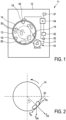
- washing machine 11 has a housing 12 with a rotating drum 14 in it being placed in a fix drum receptacle 13 surrounding it.
- Drum 14 is rotated or driven, respectively, by a drive motor 16 with drive belt 17 as is common in the art.
- a drive motor 16 with drive belt 17 as is common in the art.
- three protrusions 19 are provided in rib-like form or in the form of a triangle with a rounded tip pointing inside the drum 14.
- the protrusions 19 are shown in profile and can preferably have this form in a direction parallel to the rotation axis of drum 14.
- Drive motor 16 is driven or energized by power control unit 32, which again is controlled by control 34, preferably being the main control of the whole washing machine 11.
- Control 34 is connected to a current sensor 35 which is able to exactly supervise the drive current supplied to drive motor 16 by the power control unit 32.
- a current sensor is known in the art and can be provided by the person skilled in the art without any problem. It may also be integrated into the power control unit 32 or into the drive motor 16 itself.
- a rotation position sensor means for supervising or detecting a rotation position of the drum, which is not shown here due to the integration.
- a rotation position sensor means can be integrated into the drive motor 16 as is also common in the art, preferably as an incremental encoder.
- the rotation position sensor means is also connected to the central control 34.
- Control 34 is also provided with a storage 37 as explained before and will be explained in detail hereinafter, preferably being integrated into one semi-conductor component.
- an induction coil 40 is provided as an option. Induction coil 40 may serve to act upon an actuator inside protrusion 19, which will also be described in detail hereinafter. Induction coil 40 may also be very long along the circumferential direction of the drum receptacle 13, for example taking up a quarter or even a third of its circumference. Alternatively, a number of single and rather small induction coils may be provided along the circumference.
- drum 14 is shown with a piece of laundry 30 in it.
- a center of gravity or mass of the piece of laundry 30 is at an angle ⁇ to the vertical axis as indicated by the dashed line.
- Laundry 30 is abutted against the inside of drum 14 due to rotation of the drum 14.
- the force of gravity F GR is pointing vertically downwards.
- the centrifugal force F CE generated by the rotation of the drum and depending on its rotation speed is pointing outwards in radial direction away from a center of drum 14 and through the center of gravity of the laundry 30.
- a frictional force F FR is pointing upwards from the region of contact of laundry 30 with the inside of drum 14 in a circumferential direction or in tangential direction, respectively, which is also at right angle to the centrifugal force F CE .
- a sliding force F SL is pointing in the opposite direction of the frictional force F FR .
- the laundry 30 is moved counterclockwise with rotating drum 14 by the frictional force F FR , if it does not abut against a protrusion 19.
- the sliding force F SL is way of pulling laundry 30 downward again initiated by the gravity force F GR .
- the behavior of the laundry 30 also largely depends on the height and the shape of protrusion 19, whether the laundry 30 can slide over it instead of rotating with protrusion 19 or not. So it is easy to conceive that by changing the shape of protrusion 19 different kinds of behavior of laundry 30 can be generated and detected.
- As the speed and also the angle of rotation of drum 14 is known by way of the rotation position sensor explained before, and due to the fact that this is correlated with the position of the protrusions 19, a signal or a group of signals can be obtained which give an indication of the behavior of laundry 30, which in the end can help to distinguish which kind of fabric laundry 30 is made of, especially which is the major fiber portion, as well as potentially the size of laundry 30.
- a detection whether the piece of laundry 30 is sliding over the protrusion 19 or whether it is taken along with protrusion 19 into the rotation movement can be made by supervising the drive current of drive motor 16.
- the drive current of drive motor 16 In the first case, when laundry 30 slides over the protrusion, a slight, but noticeable ease on the drive motor and the drive current in consequence takes place for a very short span of time until the laundry 30 falls into lower part of drum 14, where it has to be put into rotational movement again, which means that additional strain has to be brought up by the drive motor 16. This results in some kind of spike in the drive current, however small this may be. This additional strain in the form of a spike or any other discontinuous change in the drive current can be detected by corresponding exact current sensor means.
- the drive current may slightly vary depending on whether the laundry 30 has to be lifted up in the right upper quadrant of drum 14 according to Fig. 2 , possibly also in the right lower quadrant. In the other two quadrants to the left side, the drive current is slightly lower. In any case, if the laundry does not slide over protrusion 19 or does not fall down, there are no discontinuous spikes in the drive current. This will be explained later on in Fig. 4 .
- Figs. 3A to 3D show the simplified result of experiments with laundry of two different types of fibers and different sizes.
- the laundry has been marked with a kind of characteristic point, and the movement of this characteristic point has then been recorded with a video camera.
- the result is shown in simplified tracks or courses that the laundry has taken. All the four figures have been recorded in the experiments with a rotation speed of 46 rpm.
- a rather small piece of laundry with a size of about 40 cm x 40 cm made from polyester has been used. It is obvious that this laundry has a low coefficient of friction and is rather lightweight. It is always sliding and does never even make a half or quarter rotational movement.
- Fig. 3B shows a rather small piece of laundry made from cotton, but with the same size. It can be seen that, on the one hand, the piece of laundry has several times been fully or almost fully rotating with drum 14, but that some times it also has been sliding over the protrusion in a way similar to Fig. 3A .
- a piece of laundry made from polyester has been used, but being four times larger than before with a size of 80 cm x 80 cm. It can be seen that the piece of laundry has been lifted somewhat higher by the protrusion during rotation of drum 14, but still is always sliding over the protrusion.
- FIG. 3D A comparable piece of laundry made from cotton again with the same size of 80 cm x 80 cm is shown in Fig. 3D , which is then mostly making the full rotation with drum 14. It is only rarely sliding over the protrusion or falling down from its top position.
- the most similar one can be found. This stands for a set of such values.
- at least one further curve for the drive current i D can be obtained, with some parameters changed, for example the shape of protrusion 19. This will result in another comparison and another verification of a most similar reference curve representing a set of such values. After a small number of such comparisons, it is usually possible to determine the values being most similar. Then the information about the details of the laundry being present inside drum 14, that has been gained by the comparison detailed before, is used for optimizing the further laundry treating process. This can be done as explained at the beginning.
- Fig. 5 shows in a side view an enlarged protrusion 19 fixed to the inside of drum 14.
- An actuator 22 is mounted on top of a metallic base 20, preferably made from or containing aluminium, and abuts with its right end against the inside of protrusion 19.
- Protrusion 19 is made from an elastic sheet material such as synthetic material or, alternatively, thin stainless steel. Actuator 22 can move to the right as is shown by the arrow into the position represented by the dotted line, thereby pushing protrusion 19 to the right side into a position of protrusion 19' in dashed line. It is easy to conceive that if the drum 14 is rotating anti-clockwise, modified protrusion 19' is allowing laundry 30 to slide over it more easily than protrusion 19.
- protrusion 19' is having a stronger hold on a piece of laundry resulting in the laundry sliding not so easily over it.
- This variation of the shape of protrusion 19 allows for even more variation of collecting information on the type and size of laundry inside drum 14 during rotation. It is a further option to influence the sliding behavior of laundry over the protrusion, which allows for an even better discrimination of the type of laundry.
- actuator 22 comprises or consists at least partly of shape changing material, which change of shape depends on temperature.
- an induction coil 40 is positioned on the outside of receptacle 13 which is controlled by control 34, as has been explained with regard to Fig. 1 .
- control 34 controls 34, as has been explained with regard to Fig. 1 .
- actuator 22 comprises or consists at least partly of shape changing material, which change of shape depends on temperature.
- an induction coil 40 is positioned on the outside of receptacle 13 which is controlled by control 34, as has been explained with regard to Fig. 1 .
- control 34 as has been explained with regard to Fig. 1 .
- Another option as an alternative is to vary the temperature of water inside drum 14, which is at least variable between room temperature of about 20 °C and elevated temperature of about 40 °C. It is also possible to provide longer or more such induction coils 40.
- a socket 24 has a socket spring 25 made of shape changing material with a temperature dependency, abutting against its base.
- a hollow rod 27 is inserted into the socket 24 containing a rod spring 28 made from conventional steel.
- Rod spring 28 abuts against the bottom of rod 27, against which socket spring 25 abuts from the other end. So the two springs 25 and 28 press one against the other.
- the right end of rod spring 28 abuts against a counterpart inside rod 27, which counterpart is affixed to the outer socket 24.
- the lower position of actuator 22 in Fig. 6 is present at a temperature of less than 30 °C.
- socket spring 25 has a length of about a third of the length of rod spring 28.
- socket spring 25 When the temperature is rising above 30 °C, for example up to 35 °C or even up to 40 °C, socket spring 25 is extending due to having passed its point of shape change. It extends by exerting more force against rod spring 28 and, at the same time, compresses rod spring 28 to result in that both springs 25 and 28 have about the same length due to a balance of their spring forces. This is the upper position of actuator 22 in Fig. 6 .
- Rod 27 is pushed out of socket 24 by some distance d, resulting in a lengthening of actuator 22 in its overall length.
- socket spring 25 By changing the temperature of actuator 22 or socket spring 25, it can be varied in its length which can be used according to Fig. 5 . It is easy to conceive that also rod spring 28 could be made of shape changing material so that the lower longer state of actuator 22 can be at a higher temperature and the upper state at a higher temperature.
- the advantage of making socket spring 25 from shape changing material is that it can be heated by base 20 and socket 24 more efficiently. It is also possible to make socket 24 from material that can be heated inductively, which would provide for a more direct heating of socket spring 25.
- the heating of base 20 or socket 24 itself is easily conceived by a person skilled in the art, for example by induction coil 40. If a change of water temperature is used to change the shape of actuator 22, this need only be done for a short time, preferably 5 minutes at most. So even laundry that should be treated with low temperatures of no more than 30 °C can be processed in this way for an analysis.
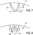
- protrusion 19 mounted to the inside of drum 14 is varied two times in its shape, for example with an actuator not shown but basically similar to the one of Fig. 5 .
- the shape of protrusion 19' in dashed lines as the first variation has a height h 2 which is slightly less than the height h 1 of protrusion 19 in its original and symmetrical state. If protrusion 19' is deformed even more, perhaps by an additional actuator with even another temperature for a shape change, it will result in protrusion 19" having a shape represented in chain dotted line.
- This protrusion 19" has an even more reduced height h 3 and, more particular, its shape is asymmetrical to such a degree that, depending on the direction of rotation of drum 14, its effect on laundry regarding sliding down or not is foreseeably very strong.
- This protrusion 19" will be able to move laundry along with it very easily and efficiently, with only very slippery pieces of laundry sliding over it instead of being taken along in the rotation of the drum 14.
- FIG. 8 Another option of changing the shape of protrusion 119 affixed to the inside of drum 114 is shown in Fig. 8 .
- Mounted onto a base 120 are two actuators 122 similar to the one of Figs. 5 and 6 , but pointing and working in opposite direction.
- actuators 22 which again contain shape changing material as explained before, they abut on the inside of protrusion 119 which has a shape as shown for example in Figs. 1 and 5 .
- the actuators 122 are activated, preferably again by a change of temperature, they are in the position according to the dotted line and push the opposite walls of protrusion 119 apart, resulting in a change of shape represented in dashed lines.
- protrusion 119' in dashed lines is still symmetrical to the same line of symmetry as protrusion 119, but somewhat flattened and also widened at its free end.
- This modified protrusion 119' has an effect onto the laundry 30 independent of the rotation direction of drum 14, but will still be noticeable.
- control 34 can distinguish which is the major part of fiber of laundry 30 inside drum 14 as well as potentially its typical size.
- a washing process that is to follow can then be adapted to this information, preferably by mainly trying to reduce the wear onto the laundry if it has been detected that it is substantially or mostly made up of synthetic fiber such as polyester. This again reduces the generation of microfibers into the sewage water of the washing process, which is of growing importance for ecological reasons.
Landscapes
- Engineering & Computer Science (AREA)
- Textile Engineering (AREA)
- Control Of Washing Machine And Dryer (AREA)
Claims (13)
- Wäschebehandlungsvorrichtung (11), insbesondere eine Waschmaschine oder ein Wäschetrockner, mit:- einer drehbaren Trommel (14, 114) mit einer Trommelumfangswand zum Einlegen der Wäsche (30),- einem Antriebsmotor (16) für die Trommel (14, 114),- mindestens einem Vorsprung (19, 119) an einer Innenseite der Trommelumfangswand, wobei- der Vorsprung (19, 119) in seiner Höhe über die Innenseite der Trommelumfangswand variabel und/oder beweglich oder flexibel ist, und/oder der Vorsprung in seiner äußeren Form variabel und/oder beweglich oder flexibel ist,- Betätigungsmittel (22) vorgesehen sind, um eine Änderung der Höhe oder Form des Vorsprungs (19, 119) zu bewirken,- eine Leistungssteuerungseinheit (32) zur Versorgung des Antriebsmotors (16) mit einem Antriebsstrom,- Stromsensormittel (35) zum Überwachen des dem Antriebsmotor (16) zugeführten Antriebsstroms,- eine Gerätesteuerung (34) mit einer Recheneinrichtung zur Berechnung einer Drehposition der Trommel (14, 114) und/oder eines Antriebsstroms aus den jeweiligen Sensormitteln (35) vorgesehen ist,gekennzeichnet durch:- Drehpositionssensormittel zum Überwachen einer Drehposition der Trommel (14, 114),- in der Recheneinrichtung ein Speicher vorgesehen ist, in dem verschiedene Gruppen von Diagrammen gespeichert sind, die für eine Abhängigkeit des Antriebsstroms der Ladung (30) in der Trommel (14, 114) sowie des Hauptfaseranteils der Wäsche (30) repräsentativ sind, wobei die Diagramme eine Variation des Antriebsstroms in Abhängigkeit von der Form des Vorsprungs (19, 119) aufweisen, der variiert wird,- die Recheneinrichtung geeignet ist, die Ladung oder das Gewicht der Wäsche (30) in der Trommel (14, 114), die typische Größe der Wäschestücke (30) in der Trommel (14, 114) und/oder den Hauptfaseranteil der Wäsche (30) zu berechnen.
- Vorrichtung nach Anspruch 1, wobei die Recheneinrichtung dazu eingerichtet ist, die Beladung oder das Gewicht der Wäsche (30) in der Trommel (14, 114) und/oder den Hauptfaseranteil der Wäsche (30) zu berechnen, um Parameter eines weiteren Wäschebehandlungsverfahrens an die erfasste Beladung und/oder den Hauptfaseranteil anzupassen, vorzugsweise im Hinblick auf die Temperatur des Wassers, die Drehgeschwindigkeit der Trommel (14, 114) oder die Form des mindestens einen Vorsprungs (19, 119).
- Vorrichtung nach einem der vorhergehenden Ansprüche, wobei das Betätigungsmittel (22) zur Veränderung der Höhe oder Form des Vorsprungs (19, 119) eine passive Betätigungseinrichtung (22) ist, vorzugsweise mit einem temperaturabhängigen formverändernden Material in Form einer Feder oder eines Schaums oder eines Stabes (20).
- Vorrichtung nach Anspruch 3, wobei die Betätigungseinrichtung (22) derart formveränderlich ist, dass bei einer Temperatur unter 30 °C eine erste Form vorliegt und dass bei einer Temperatur über 30 °C eine zweite Form vorliegt, wobei vorzugsweise über 40 °C eine dritte Form vorliegt.
- Vorrichtung nach einem der vorhergehenden Ansprüche, wobei das temperaturabhängig formverändernde Material der Betätigungseinrichtung (22) induktiv beheizbar ist, vorzugsweise aus ferromagnetischem Material besteht.
- Vorrichtung nach Anspruch 5, wobei außerhalb der Trommel (14, 114) eine Induktionsheizvorrichtung (40) fest positioniert ist, die so angeordnet ist, dass die Betätigungseinrichtung (22) radial einwärts an der Induktionsheizvorrichtung (40) vorbei läuft.
- Vorrichtung nach einem der vorhergehenden Ansprüche, wobei der Vorsprung (19, 119) aus elastischem und flexiblem Material in Form einer Wanne mit zwei längsverlaufenden Endkanten hergestellt ist, wobei der Vorsprung mit den beiden Endkanten an der Innenseite der Trommel (14, 114) derart befestigt ist, dass in einem Ausgangszustand des Vorsprungs der Vorsprung eine bestimmte Ausgangshöhe (h1) und ein bestimmtes Ausgangsprofil aufweist, wobei in mindestens einem weiteren Zustand des Vorsprungs (119) die Höhe verringert ist und der Vorsprung seitlich zur Seite entlang einer Umfangsrichtung der Trommel gebogen ist, wobei vorzugsweise in einem Ausgangszustand des Vorsprungs der Vorsprung in seinem Profil von der Seite gesehen symmetrisch ist, wobei in mindestens einem weiteren Zustand des Vorsprungs der Vorsprung seitlich zur Seite zwischen 1 cm und 3 cm gebogen ist.
- Verfahren zum Betreiben einer Wäschebehandlungsvorrichtung (11) nach einem der vorhergehenden Ansprüche, wobei:- in einem ersten Schritt verschiedene Referenzkurven für den Antriebsstrom mit einer Variation der Form des Vorsprungs (19) aufgenommen werden,- wobei für jede Referenzkurve für den Antriebsstrom die Form des Vorsprungs (19) variiert wird,- die Referenzkurven für den Antriebsstrom in dem Speicher der Recheneinrichtung gespeichert werden,- in einem zweiten Schritt, wenn Wäsche (30) in die Trommel (14, 114) eingelegt wird und tatsächlich behandelt werden soll, als zweiter Schritt vor Beginn der Behandlung der Wäsche ein Test durchgeführt wird, indem die Form des Vorsprungs (19, 119) verändert wird, wobei danach ein Vergleich mit den verschiedenen im Speicher gespeicherten Referenzkurven für den Antriebsstrom durchgeführt wird, um mindestens eine Variable der folgenden Gruppe zu bestimmen: Gewicht der Wäsche, typische Größe der Wäschestücke, Hauptfaseranteil der Wäsche,- in einem dritten Schritt wird die eigentliche Behandlung der Wäsche (30) in der Wäschebehandlungsvorrichtung (11) an das Gewicht der Wäsche, die typische Größe der Wäschestücke und/oder den Hauptfaseranteil der Wäsche angepasst.
- Verfahren nach Anspruch 8, wobei Variablen des Wäschebehandlungsprozesses an die Art der Wäsche (30) oder an den Hauptfaseranteil der Wäsche angepasst werden, vorzugsweise durch Variieren einer Temperatur des dem Wäscheprozess zugeführten Wassers und/oder einer Drehgeschwindigkeit der Trommel (14, 114) und/oder Variieren der Form des Vorsprungs (19, 119).
- Verfahren nach einem der Ansprüche 8 oder 9, wobei durch Überwachen des dem Antriebsmotor (16) zugeführten Antriebsstroms eine Kraft gemessen wird, wenn Wäschestücke (30) in der Trommel (14, 114) entlang der Innenseite der Trommelumfangswand nach unten rutschen, während sich die Trommel dreht.
- Verfahren nach Anspruch 10, wobei zusätzlich zur Messung der Kraft bzw. des dem Antriebsmotor (16) zugeführten Stroms die Position des mindestens einen Vorsprungs (19, 119) durch Auslesen der Information des Drehpositionssensors ermittelt und berücksichtigt wird.
- Verfahren nach einem der Ansprüche 8 bis 11, wobei zusätzliche Informationen von einem Wasserstandssensor oder von einem Wassermengensensor in der Trommel (14, 114) und/oder von einem Temperatursensor für die Wassertemperatur eingegeben werden.
- Verfahren nach einem der Ansprüche 8 bis 12, wobei das Verändern der Form des Vorsprungs (19, 119) im ersten Schritt und/oder im zweiten Schritt ein Verbiegen des Vorsprungs von einem Maximum in eine Richtung entlang der Umfangsrichtung der Trommel (14, 114) zu einem Maximum in die entgegengesetzte Richtung entlang der Umfangsrichtung der Trommel umfasst, wobei vorzugsweise das Verbiegen zwischen den beiden Maxima in Schritten, insbesondere in mindestens drei Schritten, erfolgt.
Priority Applications (4)
| Application Number | Priority Date | Filing Date | Title |
|---|---|---|---|
| EP18188263.0A EP3608466B1 (de) | 2018-08-09 | 2018-08-09 | Wäschebehandlungsvorrichtung und verfahren zu deren betrieb |
| US16/508,681 US20200048813A1 (en) | 2018-08-09 | 2019-07-11 | Laundry treating device and method for its operation |
| KR1020190094518A KR20200018285A (ko) | 2018-08-09 | 2019-08-02 | 세탁물 처리 장치 및 그 작동 방법 |
| CN201910734516.1A CN110863322B (zh) | 2018-08-09 | 2019-08-09 | 衣物处理装置及其操作方法 |
Applications Claiming Priority (1)
| Application Number | Priority Date | Filing Date | Title |
|---|---|---|---|
| EP18188263.0A EP3608466B1 (de) | 2018-08-09 | 2018-08-09 | Wäschebehandlungsvorrichtung und verfahren zu deren betrieb |
Publications (2)
| Publication Number | Publication Date |
|---|---|
| EP3608466A1 EP3608466A1 (de) | 2020-02-12 |
| EP3608466B1 true EP3608466B1 (de) | 2024-05-15 |
Family
ID=63207627
Family Applications (1)
| Application Number | Title | Priority Date | Filing Date |
|---|---|---|---|
| EP18188263.0A Active EP3608466B1 (de) | 2018-08-09 | 2018-08-09 | Wäschebehandlungsvorrichtung und verfahren zu deren betrieb |
Country Status (4)
| Country | Link |
|---|---|
| US (1) | US20200048813A1 (de) |
| EP (1) | EP3608466B1 (de) |
| KR (1) | KR20200018285A (de) |
| CN (1) | CN110863322B (de) |
Families Citing this family (11)
| Publication number | Priority date | Publication date | Assignee | Title |
|---|---|---|---|---|
| KR102598718B1 (ko) * | 2018-12-26 | 2023-11-06 | 엘지전자 주식회사 | 인덕션 히터를 갖는 세탁장치 및 이의 제어방법 |
| KR102598719B1 (ko) * | 2018-12-26 | 2023-11-06 | 엘지전자 주식회사 | 인덕션 히터를 갖는 세탁장치 및 이의 제어방법 |
| KR102695819B1 (ko) * | 2019-01-10 | 2024-08-16 | 엘지전자 주식회사 | 인덕션 히터를 갖는 세탁장치 및 이의 제어방법 |
| EP4123077A4 (de) * | 2020-03-16 | 2024-05-01 | LG Electronics Inc. | Vorrichtung zur behandlung von kleidung |
| DE102020213968B3 (de) | 2020-11-06 | 2022-02-17 | E.G.O. Elektro-Gerätebau GmbH | Waschmaschine und Verfahren zum Betrieb einer solchen Waschmaschine |
| DE102021207441B3 (de) | 2021-07-13 | 2022-06-02 | E.G.O. Elektro-Gerätebau GmbH | Verfahren zum Betrieb einer Waschmaschine und Waschmaschine |
| CN113417115B (zh) * | 2021-07-20 | 2023-09-22 | 珠海格力电器股份有限公司 | 一种滚筒洗衣机及其控制方法 |
| KR20230135415A (ko) * | 2022-03-16 | 2023-09-25 | 삼성전자주식회사 | 세탁기 및 세탁기의 제어방법 |
| EP4350064A1 (de) | 2022-10-06 | 2024-04-10 | E.G.O. Elektro-Gerätebau GmbH | Verfahren zum betreiben einer waschmaschine zum schleudern von wäsche und waschmaschine |
| EP4382657A1 (de) | 2022-12-05 | 2024-06-12 | E.G.O. Elektro-Gerätebau GmbH | Verfahren zum betreiben einer waschmaschine und waschmaschine |
| EP4414495A1 (de) | 2023-02-10 | 2024-08-14 | E.G.O. Elektro-Gerätebau GmbH | Verfahren zum betreiben einer waschmaschine und waschmaschine |
Family Cites Families (10)
| Publication number | Priority date | Publication date | Assignee | Title |
|---|---|---|---|---|
| US3938260A (en) * | 1974-12-11 | 1976-02-17 | Whirlpool Corporation | Adjustable baffle for appliance |
| JP2969972B2 (ja) * | 1991-01-24 | 1999-11-02 | 松下電器産業株式会社 | 衣類乾燥機の布重量検知装置 |
| DE10316879B3 (de) * | 2003-04-11 | 2004-12-09 | Diehl Ako Stiftung & Co. Kg | Verfahren zum Behandeln von Wäsche in einer Waschtrommel |
| KR100701949B1 (ko) * | 2005-02-14 | 2007-03-30 | 엘지전자 주식회사 | 드럼세탁기의 포량감지방법 |
| JP4610464B2 (ja) * | 2005-10-26 | 2011-01-12 | 三洋電機株式会社 | 洗濯脱水乾燥装置 |
| JP4364866B2 (ja) * | 2005-12-15 | 2009-11-18 | 三星電子株式会社 | 洗濯機 |
| BR112012014523B1 (pt) * | 2009-12-16 | 2020-02-11 | Electrolux Home Products Corporation N.V. | Máquina de lavar |
| US8915972B2 (en) * | 2011-05-17 | 2014-12-23 | Whirlpool Corporation | Method and apparatus for determining load fall in a laundry treating appliance |
| EP3162942B1 (de) * | 2015-10-26 | 2021-06-30 | Electrolux Appliances Aktiebolag | Wäschebehandlungsmaschine und verfahren zur bestimmung der menge von wäsche, die in eine rotierende trommel einer wäschebehandlungsmaschine geladen wird |
| US10508377B2 (en) * | 2016-10-21 | 2019-12-17 | Whirlpool Corporation | Laundry treating appliance with an adjustable height lifter |
-
2018
- 2018-08-09 EP EP18188263.0A patent/EP3608466B1/de active Active
-
2019
- 2019-07-11 US US16/508,681 patent/US20200048813A1/en not_active Abandoned
- 2019-08-02 KR KR1020190094518A patent/KR20200018285A/ko not_active Application Discontinuation
- 2019-08-09 CN CN201910734516.1A patent/CN110863322B/zh active Active
Also Published As
| Publication number | Publication date |
|---|---|
| US20200048813A1 (en) | 2020-02-13 |
| EP3608466A1 (de) | 2020-02-12 |
| KR20200018285A (ko) | 2020-02-19 |
| CN110863322B (zh) | 2023-05-30 |
| CN110863322A (zh) | 2020-03-06 |
Similar Documents
| Publication | Publication Date | Title |
|---|---|---|
| EP3608466B1 (de) | Wäschebehandlungsvorrichtung und verfahren zu deren betrieb | |
| US9285165B2 (en) | Method for controlling dryer | |
| EP2458076B1 (de) | Wäschetrockner mit Drehtrommel und Verfahren zur Steuerung eines Wäschetrockners mit Drehtrommel zum Trocknen von Feinwäsche | |
| EP2463431B1 (de) | Verfahren und Vorrichtung zur Steuerung einer Extraktionsdauer in einer Wäschebehandlungsanwendung | |
| EP2607535B1 (de) | Verfahren zum Betreiben eines Wäschebehandlungshausgeräts | |
| RU2704905C1 (ru) | Бытовой прибор для ухода за бельем с системой управления | |
| EP2014822B1 (de) | Steuerungsverfahren zur Steuerung eines Trommelwäschetrockners zur Trocknung von Wollartikeln | |
| US20130000054A1 (en) | Method of operating a laundry treating appliance to detect contact between a drum and tub | |
| US5075613A (en) | Electrical motor monitoring system for a domestic appliance | |
| US20120084997A1 (en) | Method to detect an end of cycle in a clothes dryer | |
| EP3002356B1 (de) | Wäschewaschmaschine und Steuerungsverfahren dafür | |
| EP2492388B9 (de) | Verfahren zum Wäschetrocknen | |
| CN102679419A (zh) | 加热烹调器 | |
| US8474152B2 (en) | Method to detect an empty load in a clothes dryer | |
| EP1006231A2 (de) | Verfahren zur Kontrolle der Wäschetrocknung in einem Wäschetrockner oder einer ähnlichen Maschine | |
| EP2610401B1 (de) | System und Verfahren zur Bewertung einer Wäscheladung in einem Drehtrommel-Trockner | |
| EP4414495A1 (de) | Verfahren zum betreiben einer waschmaschine und waschmaschine | |
| KR102487210B1 (ko) | 의류처리장치 | |
| EP1660712A1 (de) | Kontrollverfahren für waschtrockner | |
| KR102541175B1 (ko) | 의류처리장치 | |
| KR20240048494A (ko) | 세탁물을 회전시키는 세탁기의 작동방법 및 세탁기 | |
| CN107614777B (zh) | 洗衣机 | |
| ITTO940430A1 (it) | Metodo per l'asciugatura di biancheria e macchina implementante tale metodo. | |
| CN113106696A (zh) | 用于衣物处理设备的加热时间控制方法 | |
| CN117051561A (zh) | 一种衣料识别方法、设备及洗衣机 |
Legal Events
| Date | Code | Title | Description |
|---|---|---|---|
| PUAI | Public reference made under article 153(3) epc to a published international application that has entered the european phase |
Free format text: ORIGINAL CODE: 0009012 |
|
| STAA | Information on the status of an ep patent application or granted ep patent |
Free format text: STATUS: THE APPLICATION HAS BEEN PUBLISHED |
|
| AK | Designated contracting states |
Kind code of ref document: A1 Designated state(s): AL AT BE BG CH CY CZ DE DK EE ES FI FR GB GR HR HU IE IS IT LI LT LU LV MC MK MT NL NO PL PT RO RS SE SI SK SM TR |
|
| AX | Request for extension of the european patent |
Extension state: BA ME |
|
| STAA | Information on the status of an ep patent application or granted ep patent |
Free format text: STATUS: REQUEST FOR EXAMINATION WAS MADE |
|
| 17P | Request for examination filed |
Effective date: 20200803 |
|
| RBV | Designated contracting states (corrected) |
Designated state(s): AL AT BE BG CH CY CZ DE DK EE ES FI FR GB GR HR HU IE IS IT LI LT LU LV MC MK MT NL NO PL PT RO RS SE SI SK SM TR |
|
| STAA | Information on the status of an ep patent application or granted ep patent |
Free format text: STATUS: EXAMINATION IS IN PROGRESS |
|
| 17Q | First examination report despatched |
Effective date: 20210715 |
|
| STAA | Information on the status of an ep patent application or granted ep patent |
Free format text: STATUS: EXAMINATION IS IN PROGRESS |
|
| GRAP | Despatch of communication of intention to grant a patent |
Free format text: ORIGINAL CODE: EPIDOSNIGR1 |
|
| STAA | Information on the status of an ep patent application or granted ep patent |
Free format text: STATUS: GRANT OF PATENT IS INTENDED |
|
| RIC1 | Information provided on ipc code assigned before grant |
Ipc: D06F 105/10 20200101ALN20240117BHEP Ipc: D06F 105/46 20200101ALN20240117BHEP Ipc: D06F 103/46 20200101ALN20240117BHEP Ipc: D06F 103/04 20200101ALN20240117BHEP Ipc: D06F 105/52 20200101ALN20240117BHEP Ipc: D06F 105/00 20200101ALN20240117BHEP Ipc: D06F 39/04 20060101ALN20240117BHEP Ipc: D06F 37/06 20060101AFI20240117BHEP |
|
| INTG | Intention to grant announced |
Effective date: 20240206 |
|
| GRAS | Grant fee paid |
Free format text: ORIGINAL CODE: EPIDOSNIGR3 |
|
| GRAA | (expected) grant |
Free format text: ORIGINAL CODE: 0009210 |
|
| STAA | Information on the status of an ep patent application or granted ep patent |
Free format text: STATUS: THE PATENT HAS BEEN GRANTED |
|
| RAP3 | Party data changed (applicant data changed or rights of an application transferred) |
Owner name: E.G.O. ELEKTRO-GERAETEBAU GMBH |
|
| AK | Designated contracting states |
Kind code of ref document: B1 Designated state(s): AL AT BE BG CH CY CZ DE DK EE ES FI FR GB GR HR HU IE IS IT LI LT LU LV MC MK MT NL NO PL PT RO RS SE SI SK SM TR |
|
| REG | Reference to a national code |
Ref country code: CH Ref legal event code: EP Ref country code: GB Ref legal event code: FG4D |
|
| REG | Reference to a national code |
Ref country code: IE Ref legal event code: FG4D |
|
| REG | Reference to a national code |
Ref country code: DE Ref legal event code: R096 Ref document number: 602018069443 Country of ref document: DE |
|
| REG | Reference to a national code |
Ref country code: LT Ref legal event code: MG9D |