EP3608193B1 - Elektrisches steuergerät für ein fahrzeug sowie system damit und verfahren zum betreiben eines fahrzeugs - Google Patents
Elektrisches steuergerät für ein fahrzeug sowie system damit und verfahren zum betreiben eines fahrzeugs Download PDFInfo
- Publication number
- EP3608193B1 EP3608193B1 EP19180236.2A EP19180236A EP3608193B1 EP 3608193 B1 EP3608193 B1 EP 3608193B1 EP 19180236 A EP19180236 A EP 19180236A EP 3608193 B1 EP3608193 B1 EP 3608193B1
- Authority
- EP
- European Patent Office
- Prior art keywords
- supply connection
- control device
- outputs
- energy supply
- energy
- Prior art date
- Legal status (The legal status is an assumption and is not a legal conclusion. Google has not performed a legal analysis and makes no representation as to the accuracy of the status listed.)
- Active
Links
Images
Classifications
-
- B—PERFORMING OPERATIONS; TRANSPORTING
- B60—VEHICLES IN GENERAL
- B60L—PROPULSION OF ELECTRICALLY-PROPELLED VEHICLES; SUPPLYING ELECTRIC POWER FOR AUXILIARY EQUIPMENT OF ELECTRICALLY-PROPELLED VEHICLES; ELECTRODYNAMIC BRAKE SYSTEMS FOR VEHICLES IN GENERAL; MAGNETIC SUSPENSION OR LEVITATION FOR VEHICLES; MONITORING OPERATING VARIABLES OF ELECTRICALLY-PROPELLED VEHICLES; ELECTRIC SAFETY DEVICES FOR ELECTRICALLY-PROPELLED VEHICLES
- B60L1/00—Supplying electric power to auxiliary equipment of vehicles
-
- B—PERFORMING OPERATIONS; TRANSPORTING
- B60—VEHICLES IN GENERAL
- B60R—VEHICLES, VEHICLE FITTINGS, OR VEHICLE PARTS, NOT OTHERWISE PROVIDED FOR
- B60R16/00—Electric or fluid circuits specially adapted for vehicles and not otherwise provided for; Arrangement of elements of electric or fluid circuits specially adapted for vehicles and not otherwise provided for
- B60R16/02—Electric or fluid circuits specially adapted for vehicles and not otherwise provided for; Arrangement of elements of electric or fluid circuits specially adapted for vehicles and not otherwise provided for electric constitutive elements
- B60R16/03—Electric or fluid circuits specially adapted for vehicles and not otherwise provided for; Arrangement of elements of electric or fluid circuits specially adapted for vehicles and not otherwise provided for electric constitutive elements for supply of electrical power to vehicle subsystems or for
-
- B—PERFORMING OPERATIONS; TRANSPORTING
- B60—VEHICLES IN GENERAL
- B60W—CONJOINT CONTROL OF VEHICLE SUB-UNITS OF DIFFERENT TYPE OR DIFFERENT FUNCTION; CONTROL SYSTEMS SPECIALLY ADAPTED FOR HYBRID VEHICLES; ROAD VEHICLE DRIVE CONTROL SYSTEMS FOR PURPOSES NOT RELATED TO THE CONTROL OF A PARTICULAR SUB-UNIT
- B60W50/00—Details of control systems for road vehicle drive control not related to the control of a particular sub-unit, e.g. process diagnostic or vehicle driver interfaces
- B60W50/02—Ensuring safety in case of control system failures, e.g. by diagnosing, circumventing or fixing failures
- B60W50/023—Avoiding failures by using redundant parts
-
- F—MECHANICAL ENGINEERING; LIGHTING; HEATING; WEAPONS; BLASTING
- F16—ENGINEERING ELEMENTS AND UNITS; GENERAL MEASURES FOR PRODUCING AND MAINTAINING EFFECTIVE FUNCTIONING OF MACHINES OR INSTALLATIONS; THERMAL INSULATION IN GENERAL
- F16H—GEARING
- F16H61/00—Control functions within control units of change-speed- or reversing-gearings for conveying rotary motion ; Control of exclusively fluid gearing, friction gearing, gearings with endless flexible members or other particular types of gearing
- F16H61/0003—Arrangement or mounting of elements of the control apparatus, e.g. valve assemblies or snapfittings of valves; Arrangements of the control unit on or in the transmission gearbox
- F16H61/0006—Electronic control units for transmission control, e.g. connectors, casings or circuit boards
-
- F—MECHANICAL ENGINEERING; LIGHTING; HEATING; WEAPONS; BLASTING
- F16—ENGINEERING ELEMENTS AND UNITS; GENERAL MEASURES FOR PRODUCING AND MAINTAINING EFFECTIVE FUNCTIONING OF MACHINES OR INSTALLATIONS; THERMAL INSULATION IN GENERAL
- F16H—GEARING
- F16H61/00—Control functions within control units of change-speed- or reversing-gearings for conveying rotary motion ; Control of exclusively fluid gearing, friction gearing, gearings with endless flexible members or other particular types of gearing
- F16H61/12—Detecting malfunction or potential malfunction, e.g. fail safe ; Circumventing or fixing failures
- F16H2061/122—Avoiding failures by using redundant parts
-
- F—MECHANICAL ENGINEERING; LIGHTING; HEATING; WEAPONS; BLASTING
- F16—ENGINEERING ELEMENTS AND UNITS; GENERAL MEASURES FOR PRODUCING AND MAINTAINING EFFECTIVE FUNCTIONING OF MACHINES OR INSTALLATIONS; THERMAL INSULATION IN GENERAL
- F16H—GEARING
- F16H61/00—Control functions within control units of change-speed- or reversing-gearings for conveying rotary motion ; Control of exclusively fluid gearing, friction gearing, gearings with endless flexible members or other particular types of gearing
- F16H61/12—Detecting malfunction or potential malfunction, e.g. fail safe ; Circumventing or fixing failures
- F16H2061/1256—Detecting malfunction or potential malfunction, e.g. fail safe ; Circumventing or fixing failures characterised by the parts or units where malfunctioning was assumed or detected
- F16H2061/1292—Detecting malfunction or potential malfunction, e.g. fail safe ; Circumventing or fixing failures characterised by the parts or units where malfunctioning was assumed or detected the failing part is the power supply, e.g. the electric power supply
Definitions
- the invention relates to the field of control devices for vehicles, in particular for commercial vehicles such as trucks or the like, or for a passenger car.
- Control devices are known and are mainly used in vehicles to supply and/or control components of the vehicle.
- Components refer here in particular to electrical or electromechanical components.
- the control device usually includes an energy supply connection and outputs for supplying and/or for controlling the components.
- a control circuit is also provided. Energy is thus supplied to a control unit via the power supply connection, with which components connected to outputs of the control unit are then controlled as a function of the control unit.
- data or switching signals for example from sensors or switches, are usually available to the control unit of the control device in order to also supply the controlled components as a function of these signals.
- EP 0 692 396 B1 discloses, for example, a control device that can be installed in a trailer of a towing vehicle.
- the control unit is used to control the lighting and signaling system of the trailer vehicle in the trailer. To do this, the control unit only receives a control signal via one or two data network connections and a power supply from the towing vehicle.
- control devices are used during operation of the vehicle in addition to comfort functions, in particular for safety-related applications.
- the failure of a control device for a safety-relevant application can therefore represent a danger emanating from the vehicle and jeopardize safe driving conditions.
- control units are used to control brake actuators or in the area of manual transmissions.
- the danger of a failing control unit for the brake actuation is immediately apparent.
- a failure of a brake control device can therefore mean that braking in an emergency, but also in normal operation, cannot be carried out as desired or not at all.
- the invention relates to an electrical control unit for a vehicle or a vehicle trailer.
- the vehicle is, for example, a commercial vehicle, such as a truck or the like. According to an alternative, the vehicle is a passenger car.
- the control device includes a control unit for operating the control device.
- the control unit is, for example, an electronic or microelectronic control unit.
- An electronic or microelectronic control unit preferably has a plurality of inputs and outputs, it being possible for output signals to be generated at the outputs as a function of input signals at the inputs.
- the control unit has a logic circuit and/or a processor and a memory with a program code. The program code is loaded from the memory into the processor and executed there in order to generate the output signals depending on the input signals and also depending on the program code.
- control device includes a first power supply connection and a second power supply connection.
- control device also has outputs.
- the outputs are used for the electrically controllable connection of components.
- the components are preferably electrical or electro-mechanical components.
- Activation also includes, in particular, electrical supply of components that can be connected to the control unit in a controllable manner.
- the controller is operable to operate the controller in a first mode and in a second mode.
- a first mode a first number of outputs can be controlled with energy from the first energy supply connection.
- a second mode a second number of outputs can be controlled with energy from the second energy supply connection.
- the second number of outputs that can be controlled by the second energy supply connection in the second mode is less than the first number of outputs that can be controlled by the first energy supply connection in the first mode.
- Outputs are accordingly assigned to the first number and the second number or only to the first number. Accordingly, there are outputs that are only assigned to the first number and can therefore only be controlled in the first mode with energy from the first energy supply connection. There are also outputs that are assigned to the first number and the second number and can therefore be driven in the first mode with energy from the first energy supply connection and in the second mode with energy from the second energy supply connection.
- all of the outputs are associated with the first number and only some of the outputs are also associated with the second number.
- the control device is thus designed in such a way that it switches from a first mode to a second mode via the first power supply connection in the event of a disrupted power supply. Consequently, the control device is then supplied with energy from the second energy supply connection in order to use it to control some of the components that can be connected to the outputs.
- the function of particularly safety-relevant components can thus continue to be maintained, while less relevant functions or functions that are not even relevant to safety are suppressed.
- the energy consumption in the second mode is limited compared to the first mode in that not all outputs can be controlled. This results in the further possibility of realizing the second energy connection by means of contacts which, compared to the contacts for the first energy supply connection, are designed for lower current intensities at the same voltage. Such contacts for the second power supply connection are cheaper than contacts for the first power supply connection.
- At least one first contact partner of the first energy supply connection has a lower line resistance than at least one further first contact partner of the second energy supply connection.
- a contact partner designates a contact pin or a contact sleeve here, for example.
- the line resistance of a contact partner is to be regarded here in particular as the resistance of a contact partner that lies between two areas of the contact partner, namely between an area in which one contact partner can be electrically conductively connected to another contact partner and an area with which the contact partner can be connected to a Line or forwarding is connected in the control unit.
- the line resistance also depends on the cross-section. If the contact partners are in the form of pins according to one embodiment, a high line resistance can also be referred to as a small cross section or a low line resistance can also be referred to as a large cross section of the contact partner if the pins are made of the same material and have the same length.
- the control unit has at least one signal connection.
- the signal connection serves to supply control signals to the control device and in particular to the control unit.
- the signal connection has several contact partners.
- the contact partners of the signal connection have essentially the same line resistance.
- the line resistance of a contact partner of the signal connection and the line resistance of at least the further first contact partner of the second power supply connection are essentially the same.
- the contact partners of the signal connection and at least the further first contact partner of the second power supply connection are essentially identical.
- a single standardized control device plug can be used in order to provide signals for the signal connection on the one hand and the power supply of the control device on the other.
- Standardized control unit plugs or control unit plug connectors usually have a number of contact partners that are suitable for being electrically connected to complementary contact partners of a control unit. In this case, only two of the contact partners are designed in standardized control device plugs in order to provide a voltage or current supply for an energy supply connection. The other contact partners usually have a higher line resistance.
- the second power supply connection is provided by one or more contact partners that have the same line resistance as the contact partner(s) of the signal connection, the second power supply connection can be connected to contact partners in the control unit connector or control unit connector, which are usually used for a Signal transmission are used. This is in turn possible since the control device has to be supplied with comparatively less energy via the second energy supply connection than via the first energy supply connection during operation.
- the use of the electrical control unit is more economical and can also be integrated into an existing structure, for example.
- the first energy supply connection comprises at least one first contact partner for supplying a voltage potential, which is preferably positive.
- the second power supply connection includes at least one further first contact partner, which is also used to supply a voltage potential, which is preferably also positive.
- both energy supply connections have a common negative voltage potential, it being ensured in any case that the positive voltage potentials are provided separately for each of the energy supply connections.
- control unit is a shift control unit of a transmission control, preferably an electrical control unit of an automatic or semi-automatic transmission control.
- switching control devices are also called Transmission Control Unit (TCU).
- TCU Transmission Control Unit
- AMT automatic manual transmission
- a control device designed as a shift control device according to the invention is advantageous for ensuring a safe driving condition of a vehicle even if a supply line of the shift control device, which is connected to the first power supply connection, is interrupted.
- it can be determined by the control unit that in the second mode, in any case, the outputs are supplied with energy that make it possible for the transmission of a vehicle in such a gear ratio, in which an engine brake is effective.
- the control unit it can be ensured, for example, that when a vehicle is driving downhill and a power supply fails via the first power supply connection in the second mode of the control unit, components of the brake system are less stressed.
- control unit is set up to control at least one component, which is a valve, with at least one of the outputs.
- the valve comprises an electrical magnetic valve component and/or a pneumatic or hydraulic valve component.
- the valve is a solenoid valve.
- control unit is advantageously designed in such a way that it provides the energy required to switch a valve at at least one output.
- the first energy supply connection is set up to be connected to a primary energy source.
- the second energy supply connection is set up to be connected to an auxiliary energy source.
- control unit makes it possible to connect the first energy supply connection to the main circuit of a vehicle, for example, which includes the vehicle battery and the alternator, for example.
- the second energy supply connection is designed in such a way that it can be connected to an energy source which, for example if the primary energy source fails, still supplies sufficient energy to supply the control device in the second mode. It is therefore possible to operate the control device to a limited extent even if the primary energy source fails.
- the invention includes a system with a controller according to one of the aforementioned embodiments.
- the system also includes at least a component that is an electrical or electro-mechanical component.
- the at least one component can be electrically connected to at least one of the outputs or is operationally connected.
- the system has a primary energy source and an auxiliary energy source.
- the primary energy source is electrically connectable or operationally connected to the first energy supply connection and the auxiliary energy source is electrically connectable to the second energy supply connection.
- the at least one component comprises at least a first and a second component. At least during operation, the first component is connected to a first one of the outputs and the second component is connected to a second one of the outputs. According to the embodiment, the first and the second output are associated with the first number of outputs. Also, only the second output of the first and second outputs is also associated with the second plurality of outputs. Accordingly, the first output is not associated with the second number of outputs.
- the first and second components can be controlled in the first mode and only the second component can be controlled in the second mode.
- the maximum energy that must be provided by the second energy supply connection for activation is lower than the maximum energy that must be provided by the first energy supply connection.
- a correspondingly more favorable design of the contact partners of the second energy supply connection is therefore possible.
- the invention also includes a method for operating a vehicle by controlling components with a control device according to one of the aforementioned specific embodiments or with a system according to one of the aforementioned specific embodiments.
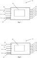
- the control unit 10 comprises a first energy supply connection 12 and a second energy supply connection 14.
- the first energy supply connection can be connected to an energy source, for example a battery of a vehicle, in order to supply the control unit 10 with electrical energy.
- the second energy supply connection 14 is also provided in order to supply the control unit 10 with electrical energy, with an energy source that can be connected to the second energy supply connection preferably being an auxiliary energy source.
- the control unit 10 includes a signal connection 15.
- the signal connection 15 is used to supply control or switching signals.
- control unit includes outputs 16-26.
- Outputs 16-26 are used to electrically control components. These components are, for example, electrical or electromechanical components, such as a valve or a valve component of a valve.
- control unit 10 includes a control unit 28.
- Control unit 28 is used to operate the control unit in a first mode and in a second mode.
- In 1 shows the operation of the controller in the first mode. This is shown as an example by the dashed lines of the second energy supply connection 14, which is expressed by this representation that energy can be consumed by the control device 10 via the first energy supply connection 12, wherein energy via the second energy supply connection 14 is not consumed in this mode.
- energy is therefore supplied from the first energy supply connection 12 was added, with all outputs 16-26, which are assigned to a first number of outputs 16-26, using the energy that can be received via the first power supply connection 12, can be controlled. The control takes place depending on the control unit 28.
- the first energy supply connection 12 has a first contact partner 30 .
- the second power supply connection has a further first contact partner 32 .
- the first contact partner 30 and the further first contact partner 32 do not differ except for the solid line or the dashed line in the illustration. Nevertheless, the first contact partner 30 of the first energy supply connection 12 is designed in such a way that it has a lower line resistance than the further first contact partner 32 of the second energy supply connection 14.
- the first contact partner 30 preferably has a larger cross section than the further first contact partner 32.
- contact partners of the second energy supply connection 14 are preferably designed in the same way as contact partners 34 of the signal connection 15.
- FIG. 2 shows the control unit 10 in the second mode.
- energy can be received via the second energy supply connection 14 in order to supply components. This is shown in turn by broken lines of the contact partners 30 of the first supply connection and solid lines of the contact partners 32 of the second energy supply connection 14 .
- this second mode only a second number of the outputs 16-26, namely the outputs 18 and 22, can now be supplied with energy from the second energy supply connection 14. This in turn is illustrated by the now dashed lines of terminals 16, 20, 24 and 26.
- Activation in the second mode, shown here, with the control unit 28 is therefore limited in such a way that only the outputs 18 and 22 can still be activated are, whereby a maximum power consumption is reduced compared to the first mode and thus ensures that the contact partners 32 of the second power supply connection 14 are not destroyed.
- a standardized control device connector or a standardized control device connector is possible in an embodiment of the same contact partner 32 of the second energy connection and the contact partner 34 of the signal connection 15 .
Landscapes
- Engineering & Computer Science (AREA)
- Mechanical Engineering (AREA)
- General Engineering & Computer Science (AREA)
- Power Engineering (AREA)
- Transportation (AREA)
- Automation & Control Theory (AREA)
- Human Computer Interaction (AREA)
- Valves And Accessory Devices For Braking Systems (AREA)
- Direct Current Feeding And Distribution (AREA)
- Electric Propulsion And Braking For Vehicles (AREA)
Description
- Die Erfindung betrifft den Bereich der Steuergeräte für Fahrzeuge, insbesondere für Nutzfahrzeuge, wie Lastkraftwagen oder dergleichen, oder für einen Personenkraftwagen. Steuergeräte sind bekannt und werden im Bereich von Fahrzeugen überwiegend zur Versorgung und/oder Ansteuerung von Komponenten des Fahrzeugs eingesetzt. Komponenten bezeichnen hier insbesondere elektrische oder elektro-mechanische Komponenten.
- Üblicherweise umfasst das Steuergerät einen Energieversorgungsanschluss und Ausgänge zur Versorgung und/oder zur Ansteuerung der Komponenten. Außerdem ist eine Steuerschaltung vorgesehen. Somit wird einem Steuergerät über den Energieversorgungsanschluss Energie zugeführt, mit der dann an Ausgängen des Steuergeräts angeschlossene Komponenten in Abhängigkeit der Steuereinheit angesteuert werden. Hierbei stehen der Steuereinheit des Steuergeräts üblicherweise Daten- oder Schaltsignale, beispielsweise von Sensoren oder Schaltern, zur Verfügung, um die angesteuerten Komponenten auch in Abhängigkeit dieser Signale zu versorgen.
- Im Dokument
EP 0 692 396 B1 wird beispielsweise ein Steuergerät offenbart, das in einem Anhänger eines Zugfahrzeugs einbaubar ist. Das Steuergerät dient, um im Anhänger die Beleuchtungs- und Signalanlage des Anhängerfahrzeugs anzusteuern. Hierfür erhält das Steuergerät lediglich ein Steuersignal über einen oder zwei Datennetzanschlüsse sowie eine Spannungsversorgung vom Zugfahrzeug. - Der Ausfall eines derartigen Steuergeräts oder ein Defekt bereits einer einzigen der Anschlussleitungen würde demnach zu einem kompletten Ausfall der Beleuchtungs- und Signalanlage des Anhängerfahrzeugs führen.
-
DE112006001741 T5 ,US2006/222910A1 ,DE102012221570A1 offenbaren Steuergeräte für Fahrzeuge gemäss dem Stand der Technik. - Demnach werden Steuergeräte im Betrieb des Fahrzeugs neben Komfortfunktionen also insbesondere auch für sicherheitsrelevante Anwendungen eingesetzt. Der Ausfall eines Steuergeräts für eine sicherheitsrelevante Anwendung kann somit eine vom Fahrzeug ausgehende Gefahr darstellen und einen sicheren Fahrzustand gefährden.
- Beispielsweise werden Steuergeräte zum Ansteuern von Bremsaktuatoren oder im Bereich des Schaltgetriebes verwendet. Unmittelbar ersichtlich ist die Gefahr durch ein ausfallendes Steuergerät für die Bremsansteuerung. Ein Ausfall eines Bremssteuergeräts kann demnach dazu führen, dass eine Bremsung im Notfall, aber auch bereits im normalen Betrieb, nicht wie gewünscht oder gar nicht ausgeführt werden kann.
- Es sind daher unterschiedliche Mechanismen oder Maßnahmen bekannt, um eine Ausfallwahrscheinlichkeit von Steuergeräten insbesondere im Bereich sicherheitsrelevanter Anwendungen zu minimieren. Hierbei ist bekannt, dass eine der häufigsten Ursache für einen Ausfall eines Steuergeräts ist, dass dessen Energieversorgung zum Beispiel durch einen Leitungsbruch oder ein Durchbrennen einer Sicherung versagt. Um dem zu begegnen, ist beispielsweise in dem Dokument
DE 10 2014 215 263 A1 offenbart, ein Steuergerät mit einer redundanten Energieversorgung auszustatten, um im Falle des Ausfalls der Primärenergie auf die Hilfs- oder Sekundärenergie umzuschalten. - Allen derartigen Mechanismen oder Maßnahmen zur Verbesserung der Betriebssicherheit von Steuergeräten ist gemeinsam, dass diese verhältnismäßig kostenaufwendig sind und im Verhältnis nur sehr selten zum Einsatz kommen. Ein Kosten-Nutzen-Verhältnis für diese Mechanismen oder Maßnahmen zur Verbesserung der Betriebssicherheit ist demnach im Vergleich zu den Funktionen eines Steuergeräts, die für den normalen Betrieb vorgesehen sind, sehr schlecht.
- Es ist daher die Aufgabe der vorliegenden Erfindung, eine Sicherheitsmaßnahme zur Beibehaltung eines sicheren Zustands eines Fahrzeugs bereitzustellen, wobei die für die Maßnahme aufgewendeten Kosten möglichst gering sein sollen. Jedenfalls soll zumindest eine vorteilhafte Alternative zum Stand der Technik gefunden werden.
- Hierzu betrifft die Erfindung ein elektrisches Steuergerät für ein Fahrzeug oder einen Fahrzeuganhänger. Die Erfindung ist in den anhängenden Ansprüchen definiert. Das Fahrzeug ist beispielsweise ein Nutzfahrzeug, wie ein Lastkraftwagen oder dergleichen. Gemäß einer Alternative ist das Fahrzeug ein Personenkraftwagen.
- Das Steuergerät umfasst eine Steuereinheit zum Betreiben des Steuergeräts. Die Steuereinheit ist beispielsweise eine elektronische oder mikroelektronische Steuereinheit. Eine elektronische oder mikroelektronische Steuereinheit weist vorzugsweise mehrere Eingänge und Ausgänge auf, wobei an den Ausgängen Ausgangssignale in Abhängigkeit von Eingangssignalen an den Eingängen erzeugbar sind. Die Steuereinheit weist insbesondere eine logische Schaltung und/oder einen Prozessor und einen Speicher mit einem Programmcode auf. Der Programmcode wird vom Speicher in den Prozessor geladen und dort ausgeführt, um die Ausgangssignale in Abhängigkeit der Eingangssignale und auch in Abhängigkeit des Programmcodes zu erzeugen.
- Außerdem umfasst das erfindungsgemäße Steuergerät einen ersten Energieversorgungsanschluss und einen zweiten Energieversorgungsanschluss. Neben den Energieversorgungsanschlüssen weist das Steuergerät auch Ausgänge auf. Die Ausgänge dienen zum elektrisch ansteuerbaren Verbinden von Komponenten. Die Komponenten sind vorzugsweise elektrische oder elektro-mechanische Komponenten. Ein Ansteuern umfasst insbesondere auch ein elektrisches Versorgen steuerbar an das Steuergerät anschließbarer Komponenten.
- Die Steuereinheit ist betreibbar, um das Steuergerät in einem ersten Modus und in einem zweiten Modus zu betreiben. In einem ersten Modus ist eine erste Anzahl der Ausgänge mit Energie vom ersten Energieversorgungsanschluss ansteuerbar. Im zweiten Modus ist eine zweite Anzahl der Ausgänge mit Energie vom zweiten Energieversorgungsanschluss ansteuerbar.
- Hierbei ist die zweite Anzahl der Ausgänge, die im zweiten Modus vom zweiten Energieversorgungsanschluss ansteuerbar sind, geringer als die erste Anzahl der Ausgänge, die im ersten Modus vom ersten Energieversorgungsanschluss ansteuerbar sind.
- Es wird also zwischen einer ersten Anzahl und einer zweiten Anzahl der Ausgänge unterschieden. Ausgänge sind demnach jeweils der ersten Anzahl und der zweiten Anzahl oder nur der ersten Anzahl zugeordnet. Es gibt demnach Ausgänge, die nur der ersten Anzahl zugeordnet sind und demnach nur im ersten Modus mit Energie vom ersten Energieversorgungsanschluss ansteuerbar sind. Außerdem gibt es Ausgänge, die der ersten Anzahl und der zweiten Anzahl zugeordnet sind und demnach im ersten Modus mit Energie vom ersten Energieversorgungsanschluss und im zweiten Modus mit Energie vom zweiten Energieversorgungsanschluss ansteuerbar sind.
- Vorzugsweise sind alle Ausgänge der ersten Anzahl zugeordnet und nur ein Teil der Ausgänge ist auch der zweiten Anzahl zugeordnet.
- Das Steuergerät ist somit derart ausgebildet, um im Fall einer gestörten Energieversorgung über den ersten Energieversorgungsanschluss von einem ersten in einen zweiten Modus zu schalten. Folglich wird dann das Steuergerät mit Energie vom zweiten Energieversorgungsanschluss versorgt, um damit einen Teil der mit den Ausgängen verbindbaren Komponenten anzusteuern.
- Im zweiten Modus kann somit die Funktion besonders sicherheitsrelevanter Komponenten weiter aufrechterhalten werden, während weniger relevante oder für die Sicherheit sogar nicht relevante Funktionen unterdrückt werden.
- Insgesamt wird also die Energieaufnahme im zweiten Modus gegenüber dem ersten Modus dadurch begrenzt, dass nicht mehr alle Ausgänge ansteuerbar sind. Hierdurch ergibt sich die weitere Möglichkeit, den zweiten Energieanschluss durch Kontakte zu realisieren, die gegenüber den Kontakten für den ersten Energieversorgungsanschluss für geringere Stromstärken bei gleicher Spannung ausgelegt sind. Derartige Kontakte für den zweiten Energieversorgungsanschluss sind günstiger als Kontakte für den ersten Energieversorgungsanschluss.
- Gemäß einer ersten Ausführungsform weist zumindest ein erster Kontaktpartner des ersten Energieversorgungsanschlusses einen geringeren Leitungswiderstand auf als zumindest ein weiterer erster Kontaktpartner des zweiten Energieversorgungsanschlusses. Ein Kontaktpartner bezeichnet hier beispielsweise einen Kontaktstift oder eine Kontakthülse. Der Leitungswiderstand eines Kontaktpartners ist hier insbesondere als der Widerstand eines Kontaktpartners anzusehen, der zwischen zwei Bereichen des Kontaktpartners liegt, nämlich zwischen einem Bereich, in dem ein Kontaktpartner mit einem anderen Kontaktpartner elektrisch leitend verbindbar ist, und einem Bereich, mit dem der Kontaktpartner mit einer Leitung oder Weiterleitung in dem Steuergerät verbunden ist.
- Der Leitungswiderstand ist neben einem spezifischen Widerstand und der Länge einer Leitung auch vom Querschnitt abhängig. Sind die Kontaktpartner gemäß einer Ausführungsform als Stifte ausgebildet, so kann grundsätzlich bei gleichem Material und gleicher Länge der Stifte ein großer Leitungswiderstand auch als kleiner Querschnitt oder ein kleiner Leitungswiderstand auch als großer Querschnitt des Kontaktpartners bezeichnet werden.
- Somit ist es möglich, dass bei gleicher Spannung über den ersten Energieversorgungsanschluss im Verhältnis mehr Strom fließen kann als über den zweiten Energieversorgungsanschluss, um im ersten Modus mehr Ausgänge des Steuergeräts ansteuern zu können, als im zweiten Modus. Hierdurch kann der oder die Kontaktpartner des zweiten Energieversorgungsanschlusses im Verhältnis kleiner gewählt werden als der oder die Kontaktpartner des ersten Energieversorgungsanschlusses. Eine günstige Auslegung des zweiten Energieversorgungsanschlusses ist somit möglich.
- Gemäß einer weiteren Ausführungsform weist das Steuergerät mindestens einen Signalanschluss auf. Der Signalanschluss dient zum Zuführen von Steuersignalen zum Steuergerät und insbesondere zur Steuereinheit. Der Signalanschluss weist mehrere Kontaktpartner auf. Die Kontaktpartner des Signalanschlusses weisen einen im Wesentlichen gleichen Leitungswiderstand auf. Hierbei sind der Leitungswiderstand eines Kontaktpartners des Signalanschlusses und der Leitungswiderstand zumindest des Weiteren ersten Kontaktpartners des zweiten Energieversorgungsanschlusses im Wesentlichen gleich. Vorzugsweise sind die Kontaktpartner des Signalanschlusses und zumindest der weitere erste Kontaktpartner des zweiten Energieversorgungsanschlusses im Wesentlichen sogar identisch ausgebildet.
- Dank diesem Ausführungsbeispiel kann ein einzelner standardisierter Steuergerätestecker verwendet werden, um einerseits Signale für den Signalanschluss und andererseits die Energieversorgung des Steuergeräts bereitzustellen.
- Standardisierte Steuergerätestecker oder Steuergerätesteckverbinder weisen üblicherweise mehrere Kontaktpartner auf, die geeignet sind, um mit komplementären Kontaktpartnern eines Steuergeräts elektrisch verbunden zu werden. Hierbei sind in standardisierten Steuergerätesteckern lediglich zwei der Kontaktpartner ausgestaltet, um eine Spannungs- oder Stromversorgung für einen Energieversorgungsanschluss bereitzustellen. Die übrigen Kontaktpartner weisen in der Regel einen höheren Leitungswiderstand auf.
- Wird demnach der zweite Energieversorgungsanschluss durch einen oder mehrere Kontaktpartner bereitgestellt, die den gleichen Leitungswiderstand aufweisen, wie der oder die Kontaktpartner des Signalanschlusses, so kann der zweite Energieversorgungsanschluss mit Kontaktpartnern im Steuergerätestecker oder Steuergerätesteckverbinder verbunden werden, die üblicherweise für eine Signalübertragung verwendet werden. Dies ist wiederrum möglich, da dem Steuergerät eine vergleichsweise geringere Energie über den zweiten Energieversorgungsanschluss als über den ersten Energieversorgungsanschluss im Betrieb zugeführt werden muss.
- Durch Verwenden eines Standardsteckers ist der Einsatz des elektrischen Steuergeräts günstiger und beispielsweise auch in eine bereits vorhandene Struktur integrierbar.
- Gemäß einer weiteren Ausführungsform umfasst der erste Energieversorgungsanschluss zumindest einen ersten Kontaktpartner zum Zuführen eines Spannungspotentials, das vorzugsweise positiv ist. Der zweite Energieversorgungsanschluss umfasst zumindest einen weiteren ersten Kontaktpartner, der ebenfalls zum Zuführen eines Spannungspotentials dient, das vorzugsweise ebenfalls positiv ist.
- Es kann demnach vorgesehen sein, dass beide Energieversorgungsanschlüsse ein gemeinsames negatives Spannungspotential haben, wobei jedenfalls sichergestellt ist, dass die positiven Spannungspotentiale für jeden der Energieversorgungsanschlüsse separat bereitgestellt werden.
- Gemäß der Erfindung ist das Steuergerät ein Schaltsteuergerät einer Getriebesteuerung, vorzugsweise ein elektrisches Steuergerät einer automatischen oder halbautomatischen Getriebesteuerung. Derartige Schaltsteuergeräte werden auch Transmission Control Unit (TCU) genannt. Ein Beispiel für eine Getriebesteuerung ist eine sogenannte Automatic Manual Transmission (AMT).
- Ein als Schaltsteuergerät ausgebildetes Steuergerät gemäß der Erfindung ist vorteilhaft, um einen sicheren Fahrzustand eines Fahrzeugs zu gewährleisten, auch wenn eine Versorgungsleitung des Schaltsteuergeräts, die mit dem ersten Energieversorgungsanschluss verbunden ist, unterbrochen wird. Hierbei kann durch die Steuereinheit festgelegt werden, dass im zweiten Modus jedenfalls die Ausgänge mit Energie versorgt werden, die es ermöglichen, das Getriebe eines Fahrzeugs in eine derartige Übersetzung zu schalten, bei der eine Motorbremse wirksam wird. Hierdurch kann beispielsweise sichergestellt werden, dass bei Bergabfahrt eines Fahrzeugs und Ausfall einer Energieversorgung über den ersten Energieversorgungsanschluss im zweiten Modus des Steuergeräts Komponenten der Bremsanlage weniger belastet werden.
- Gemäß der Erfindung ist das Steuergerät eingerichtet, mit mindestens einem der Ausgänge mindestens eine Komponente anzusteuern, die ein Ventil ist. Das Ventil umfasst insbesondere eine elektrische Magnet-Ventilkomponente und/oder eine pneumatische oder hydraulische Ventilkomponente. Besonders bevorzugt ist das Ventil ein Solenoidventil.
- Das heißt, dass das Steuergerät vorteilhafterweise derart ausgebildet ist, um die benötigte Energie zum Schalten eines Ventils an mindestens einem Ausgang bereitzustellen.
- Gemäß einer weiteren Ausführungsform ist der erste Energieversorgungsanschluss eingerichtet, mit einer Primärenergiequelle verbunden zu werden. Alternativ oder zusätzlich ist der zweite Energieversorgungsanschluss eingerichtet, mit einer Hilfsenergiequelle verbunden zu werden.
- Durch eine derartige Ausbildung des Steuergeräts wird es ermöglicht, den ersten Energieversorgungsanschluss beispielsweise mit dem Hauptstromkreis eines Fahrzeugs, der beispielsweise die Fahrzeugbatterie sowie die Lichtmaschine umfasst, verbunden zu werden. Der zweite Energieversorgungsanschluss ist demgegenüber so ausgestaltet, dass dieser mit einer Energiequelle verbindbar ist, die beispielsweise bei Ausfall der Primärenergiequelle immer noch genügend Energie zur Versorgung des Steuergeräts im zweiten Modus liefert. Somit ist auch bei Ausfall der Primärenergiequelle ein Betreiben des Steuergeräts in eingeschränktem Umfang möglich.
- Außerdem umfasst die Erfindung ein System mit einer Steuerung nach einer der vorgenannten Ausführungsformen. Das System umfasst zudem wenigstens eine Komponente, die eine elektrische oder elektro-mechanische Komponente ist. Weiter ist die wenigstens eine Komponente mit wenigstens einem der Ausgänge elektrisch verbindbar oder im Betrieb verbunden.
- Gemäß einer Ausführungsform weist das System eine Primärenergiequelle und einer Hilfsenergiequelle auf. Die Primärenergiequelle ist mit dem ersten Energieversorgungsanschluss und die Hilfsenergiequelle ist mit dem zweiten Energieversorgungsanschluss elektrisch verbindbar oder im Betrieb verbunden.
- Gemäß einer weiteren Ausführungsform umfasst die wenigstens eine Komponente zumindest eine erste und eine zweite Komponente. Zumindest im Betrieb ist die erste Komponente an einem ersten Ausgang der Ausgänge und die zweite Komponente an einem zweiten Ausgang der Ausgänge angeschlossen. Gemäß der Ausführungsform sind der erste und der zweite Ausgang der ersten Anzahl von Ausgängen zugeordnet. Außerdem ist nur der zweite Ausgang des ersten und zweiten Ausgangs auch der zweiten Anzahl von Ausgängen zugeordnet. Demnach ist der erste Ausgang nicht der zweiten Anzahl von Ausgängen zugeordnet.
- Demnach sind im ersten Modus die erste und zweite Komponente und im zweiten Modus nur die zweite Komponente ansteuerbar. Hierdurch ist die Energie, die vom zweiten Energieversorgungsanschluss zur Ansteuerung maximal bereitgestellt werden muss, geringer als die Energie, die vom ersten Energieversorgungsanschluss maximal bereitgestellt werden muss. Eine entsprechend günstigere Auslegung der Kontaktpartner des zweiten Energieversorgungsanschlusses ist somit möglich.
- Außerdem umfasst die Erfindung ein Verfahren zum Betrieb eines Fahrzeugs unter Ansteuern von Komponenten mit einem Steuergerät nach einem der vorgenannten Ausführungsformen oder mit einem System nach einer der vorgenannten Ausführungsformen.
- Weitere Ausführungsformen ergeben sich anhand der in der Figurenbeschreibung näher erläuterten Ausführungsbeispiele. Hierbei zeigen
-
Fig. 1 : ein elektrisches Steuergerät gemäß einer ersten Ausführungsform im ersten Modus und -
Fig. 2 : ein Steuergerät im zweiten Modus. -
Fig. 1 zeigt ein elektrisches Steuergerät 10. Das Steuergerät 10 umfasst einen ersten Energieversorgungsanschluss 12 und einen zweiten Energieversorgungsanschluss 14. Der erste Energieversorgungsanschluss ist mit einer Energiequelle, beispielsweise einer Batterie eines Fahrzeugs verbindbar, um das Steuergerät 10 mit elektrischer Energie zu versorgen. Ebenfalls ist der zweite Energieversorgungsanschluss 14 vorgesehen, um das Steuergerät 10 mit elektrischer Energie zu versorgen, wobei eine an den zweiten Energieversorgungsanschluss anschließbare Energiequelle vorzugsweise eine Hilfsenergiequelle ist. Außerdem umfasst das Steuergerät 10 einen Signalanschluss 15. Der Signalanschluss 15 dient zum Zuführen von Steuer- oder Schaltsignalen. - Zudem umfasst das Steuergerät Ausgänge 16-26. Die Ausgänge 16-26 dienen zum elektrischen Ansteuern von Komponenten. Diese Komponenten sind beispielsweise elektrische oder elektro-mechanische Komponenten, wie beispielsweise ein Ventil oder eine Ventilkomponente, eines Ventils.
- Außerdem umfasst das Steuergerät 10 eine Steuereinheit 28. Die Steuereinheit 28 dient zum Betreiben des Steuergeräts in einem ersten Modus und in einem zweiten Modus. In
Fig. 1 ist der Betrieb des Steuergeräts im ersten Modus dargestellt. Dies ist exemplarisch durch die gestrichelten Linien des zweiten Energieversorgungsanschlusses 14 dargestellt, wobei durch diese Darstellung ausgedrückt wird, dass Energie über den ersten Energieversorgungsanschluss 12 vom Steuergerät 10 aufgenommen werden kann, wobei Energie über den zweiten Energieversorgungsanschluss 14 in diesem Modus nicht aufgenommen wird. In diesem ersten Modus wird demnach eine Energie vom ersten Energieversorgungsanschluss 12 aufgenommen, wobei alle Ausgänge 16-26, die einer ersten Anzahl der Ausgänge 16-26 zugeordnet sind, mit Hilfe der Energie, die über den ersten Energieversorgungsanschluss 12 aufnehmbar ist, ansteuerbar sind. Die Ansteuerung erfolgt in Abhängigkeit der Steuereinheit 28. - Weiter weist der erste Energieversorgungsanschluss 12 einen ersten Kontaktpartner 30 auf. Der zweite Energieversorgungsanschluss weist einen weiteren ersten Kontaktpartner 32 auf. Der erste Kontaktpartner 30 und der weitere erste Kontaktpartner 32 unterscheiden sich bis auf die durchgängige Linie bzw. die gestrichelte Linie in der Darstellung nicht. Dennoch ist der erste Kontaktpartner 30 des ersten Energieversorgungsanschlusses 12 derart ausgebildet, dass er einen geringeren Leitungswiderstand aufweist als der weitere erste Kontaktpartner 32 des zweiten Energieversorgungsanschlusses 14. Vorzugsweise weist der erste Kontaktpartner 30 einen größeren Querschnitt auf als der weitere erste Kontaktpartner 32.
- Über den ersten Energieversorgungsanschluss 12 ist demnach ein höherer Strom bei gleicher Spannung als über den zweiten Energieversorgungsanschluss 14 aufnehmbar. Hierdurch sind Kontaktpartner des zweiten Energieversorgungsanschlusses 14 vorzugsweise so ausgebildet wie Kontaktpartner 34 des Signalanschlusses 15.
-
Fig. 2 zeigt das Steuergerät 10 im zweiten Modus. In diesem Modus ist Energie über den zweiten Energieversorgungsanschluss 14 aufnehmbar, um Komponenten zu versorgen. Dies ist wiederum durch nun gestrichelte Linien der Kontaktpartner 30 des ersten Versorgungsanschlusses und durchgängig gezeichneter Linien der Kontaktpartner 32 des zweiten Energieversorgungsanschlusses 14 dargestellt. In diesem zweiten Modus ist nun nur noch eine zweite Anzahl der Ausgänge 16-26, nämlich die Ausgänge 18 und 22, mit Energie vom zweiten Energieversorgungsanschluss 14 versorgbar. Dies ist wiederrum durch die nun gestrichelten Linien der Anschlüsse 16, 20, 24 und 26 dargestellt. Ein Ansteuern im zweiten, hier dargestellten, Modus mit der Steuereinheit 28 ist also derart begrenzt, dass lediglich noch die Ausgänge 18 und 22 ansteuerbar sind, wodurch eine maximale Stromaufnahme gegenüber dem ersten Modus reduziert ist und damit gewährleistet wird, dass die Kontaktpartner 32 des zweiten Energieversorgungsanschlusses 14 nicht zerstört werden. - Vorteilhafterweise ist bei einer Ausgestaltung gleichförmiger Kontaktpartner 32 des zweiten Energieanschlusses und der Kontaktpartner 34 des Signalanschlusses 15 der Einsatz eines standardisierten Steuergerätesteckers oder eines standardisierten Steuergerätesteckverbinders möglich.
-
- 10
- elektrisches Steuergerät
- 12
- erster Energieversorgungsanschluss
- 14
- zweiter Energieversorgungsanschluss
- 15
- Signalanschluss
- 16-26
- Ausgänge
- 28
- Steuereinheit
- 30
- erster Kontaktpartner des ersten Energieversorgungsanschlusses
- 32
- weiterer erster Kontaktpartner des zweiten Energieversorgungs-anschlusses
- 34
- Kontaktpartner des Signalanschlusses
Claims (9)
- Elektrisches Steuergerät (10) für einen Fahrzeuganhänger oder ein Fahrzeug, wobei das elektrische Steuergerät (10) ein Schaltsteuergerät (TCU, Transmission Control Unit) für eine Getriebesteuerung ist, umfassend:- eine Steuereinheit (28) zum Betreiben des Steuergeräts (10), - einen ersten Energieversorgungsanschluss (12), - einen zweiten Energieversorgungsanschluss (14) und - mehrere Ausgänge (16-26) zum elektrischen Ansteuern, insbesondere elektrischen Versorgen, von steuerbar an das Steuergerät anschließbaren Komponenten, die elektrische oder elektro-mechanische Komponenten sind, wobei die Steuereinheit (28) zum Betreiben des Steuergeräts (10) in einem ersten Modus und in einem zweiten Modus betreibbar ist, wobei im ersten Modus eine erste Anzahl der Ausgänge mit Energie vom ersten Energieversorgungsanschluss ansteuerbar ist und im zweiten Modus eine zweite Anzahl der Ausgänge mit Energie vom zweiten Energieversorgungsanschluss ansteuerbar ist wobei einige der genannten mehreren Ausgänge nur der ersten Anzahl zugeordnet sind, andere der genannten mehreren Ausgänge der ersten und der zweiten Anzahl zugeordnet sind, so dass die letztgenannten Ausgänge in beiden Modi mit Energie ansteuerbar sind, wobei des Weiteren die zweite Anzahl geringer ist als die erste Anzahl, wobei das Steuergerät eingerichtet ist, mit mindestens einem der Ausgänge eine Komponente anzusteuern, die ein Ventil ist, umfassend eine elektrische Magnet- Ventilkomponente und/oder eine pneumatische oder hydraulische Ventilkomponente, vorzugsweise ein Solenoidventil.
- Elektrisches Steuergerät (10) nach Anspruch 1, wobei zumindest ein erster Kontaktpartner (30) des ersten Energieversorgungsanschlusses (12) einen geringeren Leitungswiderstand als zumindest ein weiterer erster Kontaktpartner (32) des zweiten Energieversorgungsanschlusses (14) aufweist.
- Elektrisches Steuergerät (10) nach Anspruch 2, wobei das Steuergerät mindestens einen Signalanschluss (15) zum Zuführen von Steuersignalen mit mehreren Kontaktpartnern (34) aufweist, die jeweils einen im Wesentlichen gleichen Leitungswiderstand aufweisen, wobei der Leitungswiderstand mindestens eines Kontaktpartners (34) des Signalanschlusses (15) und der Leitungswiderstand zumindest des weiteren ersten Kontaktpartners (32) des zweiten Energieversorgungsanschlusses (14) im Wesentlichen gleich sind.
- Elektrisches Steuergerät (10) nach Anspruch 2 oder 3, wobei der erste Kontaktpartner (30) des ersten Energieversorgungsanschlusses (12) zum Zuführen eines, vorzugsweise positiven, Spannungspotentials und weitere erste Kontaktpartner (32) des zweiten Energieversorgungsanschlusses (14) zum Zuführen eines, vorzugsweise weiteren positiven, Spannungspotentials eingerichtet ist.
- Elektrisches Steuergerät (10) nach einem der vorhergehenden Ansprüche, wobei der erste Energieversorgungsanschluss (12) eingerichtet ist, mit einer Primärenergiequelle verbunden zu werden und/oder
der zweite Energieversorgungsanschluss (14) eingerichtet ist, mit einer Hilfsenergiequelle verbunden zu werden. - System mit einem elektrischen Steuergerät nach einem der Ansprüche 1 bis 5 sowie wenigstens einer Komponente, die eine elektrische oder elektro-mechanische Komponente ist, wobei die wenigstens eine Komponente mit wenigstens einem der Ausgänge (16-26) elektrisch verbindbar ist.
- System nach Anspruch 6, mit einer Primärenergiequelle und einer Hilfsenergiequelle, wobei die Primärenergiequelle mit dem ersten Energieversorgungsanschluss (12) und die Hilfsenergiequelle mit dem zweiten Energieversorgungsanschluss (14) elektrisch verbindbar sind.
- System nach Anspruch 6, wobei die wenigstens eine Komponente zumindest eine erste und eine zweite Komponente umfasst, zumindest im Betrieb die erste Komponente an einem ersten Ausgang der Ausgänge (16-26) und die zweite Komponente an einem zweiten Ausgang der Ausgänge (16-26) angeschlossen ist, wobei der erste und der zweite Ausgang der ersten Anzahl von Ausgängen (16-26) zugeordnet sind und nur der zweite Ausgang des ersten und zweiten Ausgangs auch der zweiten Anzahl von Ausgängen (16-26) zugeordnet ist.
- Verfahren zum Betrieb eines Fahrzeuganhängers oder eines Fahrzeugs, insbesondere eines Nutzfahrzeugs, wie einen Lastkraftwagen oder dergleichen, oder einen Personenkraftwagen, unter Ansteuern von elektrischen oder elektromechanischen Komponenten mit einem Steuergerät (10) nach einem der Ansprüche 1 bis 5 oder einem System nach einem der Ansprüche 6 bis 8.
Applications Claiming Priority (1)
| Application Number | Priority Date | Filing Date | Title |
|---|---|---|---|
| DE102018117447.0A DE102018117447A1 (de) | 2018-07-19 | 2018-07-19 | Elektrisches Steuergerät für ein Fahrzeug sowie System damit und Verfahren zum Betreiben eines Fahrzeugs |
Publications (2)
| Publication Number | Publication Date |
|---|---|
| EP3608193A1 EP3608193A1 (de) | 2020-02-12 |
| EP3608193B1 true EP3608193B1 (de) | 2023-08-09 |
Family
ID=66867004
Family Applications (1)
| Application Number | Title | Priority Date | Filing Date |
|---|---|---|---|
| EP19180236.2A Active EP3608193B1 (de) | 2018-07-19 | 2019-06-14 | Elektrisches steuergerät für ein fahrzeug sowie system damit und verfahren zum betreiben eines fahrzeugs |
Country Status (3)
| Country | Link |
|---|---|
| EP (1) | EP3608193B1 (de) |
| CN (1) | CN110733440A (de) |
| DE (1) | DE102018117447A1 (de) |
Citations (4)
| Publication number | Priority date | Publication date | Assignee | Title |
|---|---|---|---|---|
| US6390215B1 (en) * | 1998-05-29 | 2002-05-21 | Honda Giken Kogyo Kabushiki Kaisha | Electric vehicle |
| EP2587618A2 (de) * | 2011-10-27 | 2013-05-01 | Sanyo Electric Co. Ltd | Autostromquellenvorrichtung und mit der Stromquellenvorrichtung ausgestattetes Fahrzeug |
| DE102012221570A1 (de) * | 2012-11-26 | 2014-05-28 | Siemens Aktiengesellschaft | Elektrische Schaltungsanordnung für ein elektrisch angetriebenes Fahrzeug, Fahrzeug und entsprechendes Verfahren |
| EP2783904A2 (de) * | 2013-03-25 | 2014-10-01 | Toyota Jidosha Kabushiki Kaisha | Fahrzeugsystem |
Family Cites Families (10)
| Publication number | Priority date | Publication date | Assignee | Title |
|---|---|---|---|---|
| US4379332A (en) * | 1978-09-25 | 1983-04-05 | The Bendix Corporation | Electronic fuel injection control system for an internal combustion engine |
| DE4424471C2 (de) | 1994-07-12 | 1997-03-20 | Daimler Benz Ag | Elektrisches Anhängeranschlußgerät für ein Zugfahrzeug |
| JPH0886825A (ja) * | 1994-09-19 | 1996-04-02 | Mazda Motor Corp | 自動車の駆動回路制御装置 |
| JP4555136B2 (ja) * | 2005-03-31 | 2010-09-29 | 本田技研工業株式会社 | 燃料電池の電気システム、燃料電池車両及び電力供給方法 |
| US7443048B2 (en) * | 2005-06-30 | 2008-10-28 | Caterpillar Inc. | Method for operating an electrical system |
| WO2009145678A1 (en) * | 2008-05-26 | 2009-12-03 | Volvo Technology Corporation | Switch module for a power supply network and power supply network comprising at least one switch module |
| WO2010140253A1 (ja) * | 2009-06-05 | 2010-12-09 | トヨタ自動車株式会社 | 電気自動車および電気自動車における全体許容放電電力量設定方法 |
| CN105339853B (zh) * | 2013-06-26 | 2018-02-13 | 舍弗勒技术股份两合公司 | 带引导电流的线路的中断的检测的控制设备 |
| CN105556182B (zh) | 2013-09-19 | 2018-04-24 | 舍弗勒技术股份两合公司 | 保持机动车安全行驶状态的方法和控制执行器的控制装置 |
| JP6378119B2 (ja) * | 2015-03-16 | 2018-08-22 | 日立建機株式会社 | 制御コントローラ、ステアバイワイヤシステムおよび機械 |
-
2018
- 2018-07-19 DE DE102018117447.0A patent/DE102018117447A1/de not_active Withdrawn
-
2019
- 2019-06-14 EP EP19180236.2A patent/EP3608193B1/de active Active
- 2019-07-19 CN CN201910654803.1A patent/CN110733440A/zh active Pending
Patent Citations (4)
| Publication number | Priority date | Publication date | Assignee | Title |
|---|---|---|---|---|
| US6390215B1 (en) * | 1998-05-29 | 2002-05-21 | Honda Giken Kogyo Kabushiki Kaisha | Electric vehicle |
| EP2587618A2 (de) * | 2011-10-27 | 2013-05-01 | Sanyo Electric Co. Ltd | Autostromquellenvorrichtung und mit der Stromquellenvorrichtung ausgestattetes Fahrzeug |
| DE102012221570A1 (de) * | 2012-11-26 | 2014-05-28 | Siemens Aktiengesellschaft | Elektrische Schaltungsanordnung für ein elektrisch angetriebenes Fahrzeug, Fahrzeug und entsprechendes Verfahren |
| EP2783904A2 (de) * | 2013-03-25 | 2014-10-01 | Toyota Jidosha Kabushiki Kaisha | Fahrzeugsystem |
Also Published As
| Publication number | Publication date |
|---|---|
| DE102018117447A1 (de) | 2020-01-23 |
| EP3608193A1 (de) | 2020-02-12 |
| CN110733440A (zh) | 2020-01-31 |
Similar Documents
| Publication | Publication Date | Title |
|---|---|---|
| EP1819567B1 (de) | Elektromechanische Feststell-Bremsanlage und elektronisches System zum betreiben derselben | |
| DE112010004598T5 (de) | Elektrischgeschaltetes (Shift-By-Wire) Fahrstufenauswahlsystem für ein Schaltgetriebeund Aktuator hierfürAktuator hierfür | |
| DE19831733A1 (de) | Kraftfahrzeug mit einem elektronisch gesteuerten Automatikgetriebe und einer fremdkraftbetätigten Feststellbremse | |
| DE102012113126B4 (de) | Elektronische Schaltvorrichtung eines Fahrzeugs | |
| EP3661819B1 (de) | Kontrollsystem für ein kraftfahrzeug, kraftfahrzeug, verfahren zur kontrolle eines kraftfahrzeugs, computerprogrammprodukt und computerlesbares medium | |
| DE112014003026B4 (de) | Steuergerät | |
| WO2018087260A1 (de) | Leistungsverteiler und bordnetz mit zumindest einem leistungsverteiler | |
| EP1989470B1 (de) | Sicherheitskonzept für eine getriebestellvorrichtung | |
| DE102019207517A1 (de) | Bremssteuersystem | |
| DE102017001409A1 (de) | Verfahren und Fahrzeugsteuergerät für ein autonomes Fahrzeug und Fahrzeug | |
| DE102013101999B4 (de) | Bereichs-Schalteinrichtung | |
| WO2019224017A1 (de) | Kontrollsystem für ein kraftfahrzeug, kraftfahrzeug, verfahren zur kontrolle eines kraftfahrzeugs, computerprogrammprodukt und computerlesbares medium | |
| DE102008064421B4 (de) | Schlüsselverriegelungssteuersystem und Startvorrichtung, die ein Schlüsselverriegelungssteuersystem aufweist | |
| EP3608193B1 (de) | Elektrisches steuergerät für ein fahrzeug sowie system damit und verfahren zum betreiben eines fahrzeugs | |
| EP3691940A1 (de) | Ventilanordnung und bremssystem | |
| DE19963782B4 (de) | Steuerung für ein Fahrzeug mit einer Getriebesteuerung | |
| WO2020058030A1 (de) | Elektronische parkbremseinrichtung und verfahren zum betrieb einer elektronischen parkbremseinrichtung | |
| DE102014206925A1 (de) | Kraftfahrzeug-Bordnetz und Verfahren zum Erkennen eines Lichtbogens in einem Kraftfahrzeug-Bordnetz | |
| DE102020211902A1 (de) | Vorrichtung für ein automatisches Parkbremssystem | |
| EP2176104B1 (de) | Steuerung eines aktuators einer bremse eines kraftfahrzeugs | |
| DE102013214066A1 (de) | Steuergerät | |
| DE102005019864B4 (de) | Elektrische Lenkungsverriegelung | |
| DE102017106909B4 (de) | Schaltungseinrichtung für ein Bordnetz eines Fahrzeugs sowie Verfahren | |
| EP1283139A2 (de) | Energieversorgungseinrichtung für bordnetzgestützte, sicherheitsrelevante Systemkomponenten von Fahrzeugen | |
| EP3686056A1 (de) | Verkabelung und ansteuerungsmodul für ein anhängefahrzeug |
Legal Events
| Date | Code | Title | Description |
|---|---|---|---|
| PUAI | Public reference made under article 153(3) epc to a published international application that has entered the european phase |
Free format text: ORIGINAL CODE: 0009012 |
|
| STAA | Information on the status of an ep patent application or granted ep patent |
Free format text: STATUS: THE APPLICATION HAS BEEN PUBLISHED |
|
| AK | Designated contracting states |
Kind code of ref document: A1 Designated state(s): AL AT BE BG CH CY CZ DE DK EE ES FI FR GB GR HR HU IE IS IT LI LT LU LV MC MK MT NL NO PL PT RO RS SE SI SK SM TR |
|
| AX | Request for extension of the european patent |
Extension state: BA ME |
|
| STAA | Information on the status of an ep patent application or granted ep patent |
Free format text: STATUS: REQUEST FOR EXAMINATION WAS MADE |
|
| 17P | Request for examination filed |
Effective date: 20200812 |
|
| RBV | Designated contracting states (corrected) |
Designated state(s): AL AT BE BG CH CY CZ DE DK EE ES FI FR GB GR HR HU IE IS IT LI LT LU LV MC MK MT NL NO PL PT RO RS SE SI SK SM TR |
|
| RAP3 | Party data changed (applicant data changed or rights of an application transferred) |
Owner name: ZF CV SYSTEMS HANNOVER GMBH |
|
| STAA | Information on the status of an ep patent application or granted ep patent |
Free format text: STATUS: EXAMINATION IS IN PROGRESS |
|
| 17Q | First examination report despatched |
Effective date: 20211104 |
|
| RAP1 | Party data changed (applicant data changed or rights of an application transferred) |
Owner name: ZF CV SYSTEMS EUROPE BV |
|
| RIC1 | Information provided on ipc code assigned before grant |
Ipc: F16H 61/00 20060101ALI20230206BHEP Ipc: B60L 1/00 20060101ALI20230206BHEP Ipc: F16H 61/12 20060101ALI20230206BHEP Ipc: B60W 50/023 20120101AFI20230206BHEP |
|
| GRAP | Despatch of communication of intention to grant a patent |
Free format text: ORIGINAL CODE: EPIDOSNIGR1 |
|
| STAA | Information on the status of an ep patent application or granted ep patent |
Free format text: STATUS: GRANT OF PATENT IS INTENDED |
|
| INTG | Intention to grant announced |
Effective date: 20230417 |
|
| GRAS | Grant fee paid |
Free format text: ORIGINAL CODE: EPIDOSNIGR3 |
|
| GRAA | (expected) grant |
Free format text: ORIGINAL CODE: 0009210 |
|
| STAA | Information on the status of an ep patent application or granted ep patent |
Free format text: STATUS: THE PATENT HAS BEEN GRANTED |
|
| AK | Designated contracting states |
Kind code of ref document: B1 Designated state(s): AL AT BE BG CH CY CZ DE DK EE ES FI FR GB GR HR HU IE IS IT LI LT LU LV MC MK MT NL NO PL PT RO RS SE SI SK SM TR |
|
| REG | Reference to a national code |
Ref country code: GB Ref legal event code: FG4D Free format text: NOT ENGLISH |
|
| REG | Reference to a national code |
Ref country code: CH Ref legal event code: EP |
|
| REG | Reference to a national code |
Ref country code: IE Ref legal event code: FG4D Free format text: LANGUAGE OF EP DOCUMENT: GERMAN |
|
| REG | Reference to a national code |
Ref country code: DE Ref legal event code: R096 Ref document number: 502019008837 Country of ref document: DE |
|
| REG | Reference to a national code |
Ref country code: LT Ref legal event code: MG9D |
|
| REG | Reference to a national code |
Ref country code: NL Ref legal event code: MP Effective date: 20230809 |
|
| PG25 | Lapsed in a contracting state [announced via postgrant information from national office to epo] |
Ref country code: GR Free format text: LAPSE BECAUSE OF FAILURE TO SUBMIT A TRANSLATION OF THE DESCRIPTION OR TO PAY THE FEE WITHIN THE PRESCRIBED TIME-LIMIT Effective date: 20231110 |
|
| PG25 | Lapsed in a contracting state [announced via postgrant information from national office to epo] |
Ref country code: IS Free format text: LAPSE BECAUSE OF FAILURE TO SUBMIT A TRANSLATION OF THE DESCRIPTION OR TO PAY THE FEE WITHIN THE PRESCRIBED TIME-LIMIT Effective date: 20231209 |
|
| PG25 | Lapsed in a contracting state [announced via postgrant information from national office to epo] |
Ref country code: SE Free format text: LAPSE BECAUSE OF FAILURE TO SUBMIT A TRANSLATION OF THE DESCRIPTION OR TO PAY THE FEE WITHIN THE PRESCRIBED TIME-LIMIT Effective date: 20230809 Ref country code: RS Free format text: LAPSE BECAUSE OF FAILURE TO SUBMIT A TRANSLATION OF THE DESCRIPTION OR TO PAY THE FEE WITHIN THE PRESCRIBED TIME-LIMIT Effective date: 20230809 Ref country code: PT Free format text: LAPSE BECAUSE OF FAILURE TO SUBMIT A TRANSLATION OF THE DESCRIPTION OR TO PAY THE FEE WITHIN THE PRESCRIBED TIME-LIMIT Effective date: 20231211 Ref country code: NO Free format text: LAPSE BECAUSE OF FAILURE TO SUBMIT A TRANSLATION OF THE DESCRIPTION OR TO PAY THE FEE WITHIN THE PRESCRIBED TIME-LIMIT Effective date: 20231109 Ref country code: NL Free format text: LAPSE BECAUSE OF FAILURE TO SUBMIT A TRANSLATION OF THE DESCRIPTION OR TO PAY THE FEE WITHIN THE PRESCRIBED TIME-LIMIT Effective date: 20230809 Ref country code: LV Free format text: LAPSE BECAUSE OF FAILURE TO SUBMIT A TRANSLATION OF THE DESCRIPTION OR TO PAY THE FEE WITHIN THE PRESCRIBED TIME-LIMIT Effective date: 20230809 Ref country code: LT Free format text: LAPSE BECAUSE OF FAILURE TO SUBMIT A TRANSLATION OF THE DESCRIPTION OR TO PAY THE FEE WITHIN THE PRESCRIBED TIME-LIMIT Effective date: 20230809 Ref country code: IS Free format text: LAPSE BECAUSE OF FAILURE TO SUBMIT A TRANSLATION OF THE DESCRIPTION OR TO PAY THE FEE WITHIN THE PRESCRIBED TIME-LIMIT Effective date: 20231209 Ref country code: HR Free format text: LAPSE BECAUSE OF FAILURE TO SUBMIT A TRANSLATION OF THE DESCRIPTION OR TO PAY THE FEE WITHIN THE PRESCRIBED TIME-LIMIT Effective date: 20230809 Ref country code: GR Free format text: LAPSE BECAUSE OF FAILURE TO SUBMIT A TRANSLATION OF THE DESCRIPTION OR TO PAY THE FEE WITHIN THE PRESCRIBED TIME-LIMIT Effective date: 20231110 Ref country code: FI Free format text: LAPSE BECAUSE OF FAILURE TO SUBMIT A TRANSLATION OF THE DESCRIPTION OR TO PAY THE FEE WITHIN THE PRESCRIBED TIME-LIMIT Effective date: 20230809 |
|
| PG25 | Lapsed in a contracting state [announced via postgrant information from national office to epo] |
Ref country code: PL Free format text: LAPSE BECAUSE OF FAILURE TO SUBMIT A TRANSLATION OF THE DESCRIPTION OR TO PAY THE FEE WITHIN THE PRESCRIBED TIME-LIMIT Effective date: 20230809 |
|
| PG25 | Lapsed in a contracting state [announced via postgrant information from national office to epo] |
Ref country code: ES Free format text: LAPSE BECAUSE OF FAILURE TO SUBMIT A TRANSLATION OF THE DESCRIPTION OR TO PAY THE FEE WITHIN THE PRESCRIBED TIME-LIMIT Effective date: 20230809 |
|
| PG25 | Lapsed in a contracting state [announced via postgrant information from national office to epo] |
Ref country code: SM Free format text: LAPSE BECAUSE OF FAILURE TO SUBMIT A TRANSLATION OF THE DESCRIPTION OR TO PAY THE FEE WITHIN THE PRESCRIBED TIME-LIMIT Effective date: 20230809 Ref country code: RO Free format text: LAPSE BECAUSE OF FAILURE TO SUBMIT A TRANSLATION OF THE DESCRIPTION OR TO PAY THE FEE WITHIN THE PRESCRIBED TIME-LIMIT Effective date: 20230809 Ref country code: ES Free format text: LAPSE BECAUSE OF FAILURE TO SUBMIT A TRANSLATION OF THE DESCRIPTION OR TO PAY THE FEE WITHIN THE PRESCRIBED TIME-LIMIT Effective date: 20230809 Ref country code: EE Free format text: LAPSE BECAUSE OF FAILURE TO SUBMIT A TRANSLATION OF THE DESCRIPTION OR TO PAY THE FEE WITHIN THE PRESCRIBED TIME-LIMIT Effective date: 20230809 Ref country code: DK Free format text: LAPSE BECAUSE OF FAILURE TO SUBMIT A TRANSLATION OF THE DESCRIPTION OR TO PAY THE FEE WITHIN THE PRESCRIBED TIME-LIMIT Effective date: 20230809 Ref country code: CZ Free format text: LAPSE BECAUSE OF FAILURE TO SUBMIT A TRANSLATION OF THE DESCRIPTION OR TO PAY THE FEE WITHIN THE PRESCRIBED TIME-LIMIT Effective date: 20230809 Ref country code: SK Free format text: LAPSE BECAUSE OF FAILURE TO SUBMIT A TRANSLATION OF THE DESCRIPTION OR TO PAY THE FEE WITHIN THE PRESCRIBED TIME-LIMIT Effective date: 20230809 |
|
| REG | Reference to a national code |
Ref country code: DE Ref legal event code: R097 Ref document number: 502019008837 Country of ref document: DE |
|
| PG25 | Lapsed in a contracting state [announced via postgrant information from national office to epo] |
Ref country code: IT Free format text: LAPSE BECAUSE OF FAILURE TO SUBMIT A TRANSLATION OF THE DESCRIPTION OR TO PAY THE FEE WITHIN THE PRESCRIBED TIME-LIMIT Effective date: 20230809 |
|
| PLBE | No opposition filed within time limit |
Free format text: ORIGINAL CODE: 0009261 |
|
| STAA | Information on the status of an ep patent application or granted ep patent |
Free format text: STATUS: NO OPPOSITION FILED WITHIN TIME LIMIT |
|
| PGFP | Annual fee paid to national office [announced via postgrant information from national office to epo] |
Ref country code: GB Payment date: 20240402 Year of fee payment: 6 |
|
| 26N | No opposition filed |
Effective date: 20240513 |
|
| PG25 | Lapsed in a contracting state [announced via postgrant information from national office to epo] |
Ref country code: SI Free format text: LAPSE BECAUSE OF FAILURE TO SUBMIT A TRANSLATION OF THE DESCRIPTION OR TO PAY THE FEE WITHIN THE PRESCRIBED TIME-LIMIT Effective date: 20230809 |
|
| PGFP | Annual fee paid to national office [announced via postgrant information from national office to epo] |
Ref country code: FR Payment date: 20240408 Year of fee payment: 6 |
|
| PG25 | Lapsed in a contracting state [announced via postgrant information from national office to epo] |
Ref country code: BG Free format text: LAPSE BECAUSE OF FAILURE TO SUBMIT A TRANSLATION OF THE DESCRIPTION OR TO PAY THE FEE WITHIN THE PRESCRIBED TIME-LIMIT Effective date: 20230809 |
|
| PG25 | Lapsed in a contracting state [announced via postgrant information from national office to epo] |
Ref country code: BG Free format text: LAPSE BECAUSE OF FAILURE TO SUBMIT A TRANSLATION OF THE DESCRIPTION OR TO PAY THE FEE WITHIN THE PRESCRIBED TIME-LIMIT Effective date: 20230809 |
|
| PG25 | Lapsed in a contracting state [announced via postgrant information from national office to epo] |
Ref country code: MC Free format text: LAPSE BECAUSE OF FAILURE TO SUBMIT A TRANSLATION OF THE DESCRIPTION OR TO PAY THE FEE WITHIN THE PRESCRIBED TIME-LIMIT Effective date: 20230809 |
|
| REG | Reference to a national code |
Ref country code: CH Ref legal event code: PL |
|
| PG25 | Lapsed in a contracting state [announced via postgrant information from national office to epo] |
Ref country code: LU Free format text: LAPSE BECAUSE OF NON-PAYMENT OF DUE FEES Effective date: 20240614 |
|
| PG25 | Lapsed in a contracting state [announced via postgrant information from national office to epo] |
Ref country code: IE Free format text: LAPSE BECAUSE OF NON-PAYMENT OF DUE FEES Effective date: 20240614 |
|
| PG25 | Lapsed in a contracting state [announced via postgrant information from national office to epo] |
Ref country code: BE Free format text: LAPSE BECAUSE OF NON-PAYMENT OF DUE FEES Effective date: 20240630 Ref country code: CH Free format text: LAPSE BECAUSE OF NON-PAYMENT OF DUE FEES Effective date: 20240630 |
|
| REG | Reference to a national code |
Ref country code: BE Ref legal event code: MM Effective date: 20240630 |
|
| PGFP | Annual fee paid to national office [announced via postgrant information from national office to epo] |
Ref country code: DE Payment date: 20250402 Year of fee payment: 7 |
|
| REG | Reference to a national code |
Ref country code: AT Ref legal event code: MM01 Ref document number: 1597194 Country of ref document: AT Kind code of ref document: T Effective date: 20240614 |
|
| PG25 | Lapsed in a contracting state [announced via postgrant information from national office to epo] |
Ref country code: AT Free format text: LAPSE BECAUSE OF NON-PAYMENT OF DUE FEES Effective date: 20240614 |
|
| PG25 | Lapsed in a contracting state [announced via postgrant information from national office to epo] |
Ref country code: CY Free format text: LAPSE BECAUSE OF FAILURE TO SUBMIT A TRANSLATION OF THE DESCRIPTION OR TO PAY THE FEE WITHIN THE PRESCRIBED TIME-LIMIT; INVALID AB INITIO Effective date: 20190614 |
|
| GBPC | Gb: european patent ceased through non-payment of renewal fee |
Effective date: 20250614 |
|
| PG25 | Lapsed in a contracting state [announced via postgrant information from national office to epo] |
Ref country code: HU Free format text: LAPSE BECAUSE OF FAILURE TO SUBMIT A TRANSLATION OF THE DESCRIPTION OR TO PAY THE FEE WITHIN THE PRESCRIBED TIME-LIMIT; INVALID AB INITIO Effective date: 20190614 |