EP3608024A1 - Procédé et dispositif de marquage de l'état de contrôle d'un branchement et support de stockage informatique - Google Patents
Procédé et dispositif de marquage de l'état de contrôle d'un branchement et support de stockage informatique Download PDFInfo
- Publication number
- EP3608024A1 EP3608024A1 EP18871383.8A EP18871383A EP3608024A1 EP 3608024 A1 EP3608024 A1 EP 3608024A1 EP 18871383 A EP18871383 A EP 18871383A EP 3608024 A1 EP3608024 A1 EP 3608024A1
- Authority
- EP
- European Patent Office
- Prior art keywords
- switch
- locking
- interlocking
- marking
- control status
- Prior art date
- Legal status (The legal status is an assumption and is not a legal conclusion. Google has not performed a legal analysis and makes no representation as to the accuracy of the status listed.)
- Pending
Links
- 238000000034 method Methods 0.000 title claims abstract description 31
- 230000000903 blocking effect Effects 0.000 claims description 22
- 230000001681 protective effect Effects 0.000 claims description 15
- 230000007547 defect Effects 0.000 description 4
- 230000006870 function Effects 0.000 description 3
- 238000012544 monitoring process Methods 0.000 description 3
- 230000009471 action Effects 0.000 description 2
- 230000008569 process Effects 0.000 description 2
- 230000009286 beneficial effect Effects 0.000 description 1
- 230000008859 change Effects 0.000 description 1
- 230000010365 information processing Effects 0.000 description 1
- 238000012986 modification Methods 0.000 description 1
- 230000004048 modification Effects 0.000 description 1
Images




Classifications
-
- B—PERFORMING OPERATIONS; TRANSPORTING
- B61—RAILWAYS
- B61L—GUIDING RAILWAY TRAFFIC; ENSURING THE SAFETY OF RAILWAY TRAFFIC
- B61L19/00—Arrangements for interlocking between points and signals by means of a single interlocking device, e.g. central control
- B61L19/06—Interlocking devices having electrical operation
-
- B—PERFORMING OPERATIONS; TRANSPORTING
- B61—RAILWAYS
- B61L—GUIDING RAILWAY TRAFFIC; ENSURING THE SAFETY OF RAILWAY TRAFFIC
- B61L25/00—Recording or indicating positions or identities of vehicles or trains or setting of track apparatus
- B61L25/06—Indicating or recording the setting of track apparatus, e.g. of points, of signals
-
- B—PERFORMING OPERATIONS; TRANSPORTING
- B61—RAILWAYS
- B61L—GUIDING RAILWAY TRAFFIC; ENSURING THE SAFETY OF RAILWAY TRAFFIC
- B61L5/00—Local operating mechanisms for points or track-mounted scotch-blocks; Visible or audible signals; Local operating mechanisms for visible or audible signals
- B61L5/10—Locking mechanisms for points; Means for indicating the setting of points
Definitions
- the present disclosure relates to the field of computer control technology, in particular, to a device and method for marking switch control status, and a computer-based storage medium.
- CTCS system includes signal apparatuses such as computer interlocking apparatus, column control center apparatus, track circuit apparatus, line side central apparatus, track circuit apparatus, on-board train automatic protection apparatus, signal centralized monitoring apparatus, dispatching centralized apparatus, motor vehicle monitoring apparatus, temporary speed limit server.
- the computer interlocking apparatus performs logic calculation on the execution command of the station operator and the information indicated on the site, thereby realizing centralized control and monitoring of the switch, the route and the signal machine.
- the switch requires that it be automatically rotated by the single operation or the selection of the route.
- automatic selection should be carried out in a sequential manner.
- the individual operation of the switch shall be prior to the automatic selection of the route.
- the switch shall be subjected to route locking, section locking, protection, individual locking, total locking, power-on locking and manual blocking.
- the switch should not rotate during locking, including individual operation, route selection and driving, but the route can be arranged through the current position of the switch.
- the switch in manual blocking can be manipulated individually, but the route cannot be arranged through the switch and driven.
- the technical problem to be solved by the present disclosure is to provide a device and method for marking switch control status, and a computer-based storage medium, which solves the problem of interference among the switch markings in the prior art.
- the implementation of the present disclosure is specifically to provide a method for marking switch control status comprising steps of collecting all control status of a switch, and marking different control status with different characteristic words.
- the implementation of the present disclosure is to further provide a computer-based storage medium containing computer-executable instructions, wherein a data processing apparatus performs steps of collecting all control status of a switch, and marking different control status with different characteristic words when the computer-executable instructions are processed via the data processing apparatus.
- the implementation of the present disclosure is to further provide a device for marking switch control status comprising a collection unit for collecting all control status of a switch, and a marking unit for marking different control status with different characteristic words.
- the device and method for marking switch control status and the computer-based storage medium at least have the following beneficial effects: processing the switch control status in a manner of one characteristic word according to the control process of a switch and situations such as individual locking, power-on locking, protection, manual blocking, route locking (considering that a set of switches may be locked simultaneously by 4 routes at most) and total locking (considering that a set of switches may be locked simultaneously by three regions) may effectively save the storage space of the computer-based interlocking system while better solving the defect of overlapping conflicts of various locking status, and clears the corresponding placement problem according to the timing of the lock after the subsequent unlocking while considering the action command of the switch.
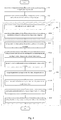
- Fig. 1 is a flow chart of Embodiment 1 of a for marking method switch control status according to a specific embodiment of the present disclosure. As shown in Fig. 1 , all of the control status are marked respectively by different characteristic words.
- the method for marking the switch control status comprises:
- processing the switch control status in a manner of using a characteristic word may effectively save the storage space of the computer-based interlocking system while better solving the defects of overlapping conflicts of various locking status, as well as facilitating the expansion of the control range of the switch, such as the use of multiple switches to meet the corresponding requirements.
- Fig. 2 is a flow chart of Embodiment 2 of a method of marking switch control status according to a specific embodiment of the present disclosure. As shown in Fig. 2 , the switch execution is controlled according to the characteristic word.
- the method for marking the switch control status further comprises: step 103: controlling the switch to execute according to the characteristic word.
- the characteristic word is a field, and the characteristic word is used to control the switch to execute, so that the execution is convenient and the control is simple.
- controlling the switch execution by the characteristic word may effectively save the storage space of the computer-based interlocking system while better solving overlapping conflicts of various locking status of the switch, so that the execution is convenient and the control is simple.
- Fig. 3 is a flow chart of Embodiment 3 of a method for marking switch control status according to a specific embodiment of the present disclosure. As shown in Fig. 3 , the switch operation and locking are controlled according to the characteristic word.
- the step 103 specifically includes:
- controlling the switch to operate and switch to lock according to the characteristic word saves the storage space of the computer-based interlocking system, and the various locking status of the switch may not overlap.
- Fig. 4 is a flow chart of Embodiment 4 of a method for marking switch control status according to a specific embodiment of the present disclosure. As shown in Fig. 4 , the switch operation and locking are controlled according to the characteristic word.
- the step 1031 specifically includes:
- the step 1032 specifically includes:
- performing the switch to operate and switch to lock according to the characteristic word saves the storage space of the computer-based interlocking system without causing the various locking status of the switch to overlap, so as to be safe and reliable, making execution convenient.
- Fig. 5 is a structural view of Embodiment 1 of a device for marking switch control status according to a specific embodiment of the present disclosure.
- the device as shown in Fig. 5 may be applied to the method as shown in Figs. 1 to 4 , and all of the control status are marked respectively by different characteristic words.
- the device for marking the switch control status comprises a collection unit 1 and a marking unit 2.
- the collection unit 1 is used for collecting all control status of a switch
- the marking unit 2 is used for marking different control status with different characteristic words.
- processing the switch control status in a manner of using a characteristic word may effectively save the storage space of the computer-based interlocking system while better solving the defects of overlapping conflicts of various locking status, as well as facilitating the expansion of the control range of the switch, such as the use of multiple switches to meet the corresponding requirements.
- Fig. 6 is a structural view of Embodiment 6 of a device of marking switch control status according to a specific embodiment of the present disclosure. As shown in Fig. 6 , a control unit controls the switch to execute according to the characteristic word.
- the device for marking the switch control status further comprises a control unit 3.
- the control unit 3 is used for controlling the switch to execute according to the characteristic word.
- controlling the switch to execute by the characteristic word may effectively save the storage space of the computer-based interlocking system while better solving overlapping conflicts of various locking status of the switch, so that the execution is convenient and the control is simple.
- Fig. 7 is a structural view of Embodiment 3 of a device of marking switch control status according to a specific embodiment of the present disclosure. As shown in Fig. 7 , a control module controls the switch to operate and switch to lock according to the characteristic word.
- control unit 3 specifically includes a first control module 31 and a second control module 32.
- first control module 31 is used for controlling the switch to operate according to the characteristic word
- second control module 32 is used for controlling the switch to lock according to the characteristic word.
- controlling the switch to operate and switch to lock according to the characteristic word saves the storage space of the computer-based interlocking system, and the various locking status of the switch may not overlap.
- Fig. 8 is a structural view of Embodiment 4 of a device of marking switch control status according to a specific embodiment of the present disclosure. As shown in Fig. 8 , the switch operation and switch to lock are controlled according to the characteristic word.
- the first control module 31 specifically includes an individual operation sub-module 311 and an automatic selection sub-module 312.
- the individual operation sub-module 311 is used for individually manipulating an interlocking switch;
- the automatic selection sub-module 312 is used for automatically selecting the interlocking switch according to a route arrangement.
- the individual operation of the interlocking switch is prior to the automatic selection of the interlocking switch.
- the second control module 32 specifically includes a first locking sub-module 321, a second locking sub-module 322, a third locking sub-module 323, a fourth locking sub-module 324, a fifth locking sub-module 325, a sixth locking sub-module 326 and a seventh locking sub-module 327.
- the first locking sub-module 321 is used for locking a switch in the route according to the route locking conditions in the centralized interlocking;
- the second locking sub-module 322 is used for locking a protective switch in the route and a branching switch in an arrival-departure track according to the route locking in the centralized interlocking;
- the third locking sub-module 323 is used for locking all switches in a section according to the section locking status in the centralized interlocking;
- the fourth locking sub-module 324 is used for locking a designated switch according to a manual individual locking command in the centralized interlocking;
- the fifth locking sub-module 325 is used for locking a designated set of switches according to a manual total locking command in the centralized interlocking;
- the sixth locking sub-module 326 is used for blocking a designated switch according to a manual blocking command in the centralized interlocking;
- the seventh locking sub-module 327 is used for locking all switches according to power-on locking status in the centralized interlocking
- performing the switch to operate and switch to lock according to the characteristic word saves the storage space of the computer-based interlocking system without causing the various locking status of the switch to overlap, so as to be safe and reliable, making execution convenient.
- the implementation of the present disclosure is to further provide a computer-based storage medium containing computer-executable instructions, wherein a data processing apparatus performs steps of:
- the implementation of the present disclosure is to further provide a computer-based storage medium containing computer-executable instructions, wherein a data processing apparatus performs steps of:
- the implementation of the present disclosure is to further provide a computer-based storage medium containing computer-executable instructions, wherein a data processing apparatus performs steps of:
- step 1031 controlling the switch to operate according to the characteristic word.
- step 1032 controlling the switch to lock according to the characteristic word.
- the implementation of the present disclosure is to further provide a computer-based storage medium containing computer-executable instructions, wherein a data processing apparatus performs steps of:
- step 10311 individually manipulating an interlocking switch.
- step 10312 automatically selecting the interlocking switch according to a route arrangement, wherein the individual operation of the interlocking switch is prior to the automatic selection of the interlocking switch.
- step 1032 controlling the switch to lock according to the characteristic word.
- the implementation of the present disclosure is to further provide a computer-based storage medium containing computer-executable instructions, wherein a data processing apparatus performs steps of:
- step 1031 controlling the switch to operate according to the characteristic word.
- step 10321 locking a switch in the route according to the route locking conditions in the centralized interlocking.
- step 10322 locking a protective switch in the route and a branching switch in an arrival-departure track according to the route locking conditions in the centralized interlocking.
- Step 10323 locking all switches in a section according to the section locking status in the centralized interlocking.
- Step 10324 locking a designated switch according to a manual individual locking command in the centralized interlocking;
- Step 10325 locking a designated set of switch according to a manual total locking command in the centralized interlocking;
- Step 10326 blocking a designated switch according to a manual blocking command in the centralized interlocking;
- Step 10327 locking all switches according to a power-on locking status in the centralized interlocking; wherein the switch or the protective switch should not be activated after the switch or the protective switch is locked.
- Fig. 9 is a flow chart of a switch execution service according to a specific embodiment of the present disclosure. As shown in Fig. 9 , after the operator presses the button, the button information processing is first performed to convert the button information into a control command, and then the control command is converted into a switch individual control command, and finally converted into a driving command.
- centralized interlocking switches should have an individual locking function (manual locking): the centralized interlocking should be able to lock the switch individually; after the switch is individually locked, the route through the switch may be arranged without switching the position; after the switch is individually locked, the switch may not be manipulated individually; the switch under the route control may be individually locked, and the unlocking of the route should not affect the switch to be locked individually; after the switch is individually locked, the individual unlocking execution for the switch may be used to unlock the switch, and if the switch is locked at the same time by the route, the individual unlocking of the switch should not affect the switch being locked by the route.
- manual locking the centralized interlocking should be able to lock the switch individually; after the switch is individually locked, the route through the switch may be arranged without switching the position; after the switch is individually locked, the switch may not be manipulated individually; the switch under the route control may be individually locked, and the unlocking of the route should not affect the switch to be locked individually; after the switch is individually locked, the individual unlocking execution for the
- centralized interlocking switches should have manual blocking functions: centralized interlocking should be able to manually block the switch; after the switch is manually blocked, the route through the switch (including the guide route) is forbidden to be arranged; after the switch is manually blocked, the switch may be operated individually; the switch under the route control may not be manually blocked; the manual blocking and individual locking of the switch should not affect each other; after the switch is manually blocked, the manual blocking of the switch may be used to unblock the switch.
- Table 2 is a check table for related execution conditions of the switch (checking required is ticked by ⁇ , otherwise ticked by x).
- the present disclosure provides a device and method for marking switch control status and a computer-based storage medium, wherein processing the switch control status in a manner of one characteristic word according to the control process of a switch and situations such as individual locking, power-on locking, protection, manual blocking, route locking (considering that a set of switches may be locked simultaneously by 4 routes at most) and total locking (considering that a set of switches may be locked simultaneously by three regions) may effectively save the storage space of the computer-based interlocking system while better solving the defect of overlapping conflicts of various locking status, and clears the corresponding placement problem according to the timing of the lock after the subsequent unlocking while considering the action command of the switch.
- processing the switch control status in a manner of one characteristic word according to the control process of a switch and situations such as individual locking, power-on locking, protection, manual blocking, route locking (considering that a set of switches may be locked simultaneously by 4 routes at most) and total locking (considering that a set of switches may be locked simultaneously by three regions) may effectively save the storage space of the computer
- an embodiment of the present disclosure may be implemented in various hardware, software code, or a combination of both.
- an embodiment of the present disclosure may also be a program code that executes the above method in a Digital Signal Processor (DSP).
- DSP Digital Signal Processor
- the present disclosure may also involve various functions performed by a computer processor, a digital signal processor, a microprocessor, or a Field Programmable Gate Array (FPGA).
- the above described processor may be configured to perform specific tasks in accordance with the present disclosure, which are accomplished by executing machine readable software code or firmware code that defines a particular method disclosed herein.
- the software code or firmware code may be developed into different programming languages and different formats or forms.
- the software code may also be compiled for different target platforms. However, different code patterns, types, and languages of the software code and other types of configuration code that perform tasks in accordance with the present disclosure do not depart from the spirit and scope of the present disclosure.
Landscapes
- Engineering & Computer Science (AREA)
- Mechanical Engineering (AREA)
- Train Traffic Observation, Control, And Security (AREA)
- Electric Propulsion And Braking For Vehicles (AREA)
Applications Claiming Priority (2)
| Application Number | Priority Date | Filing Date | Title |
|---|---|---|---|
| CN201711001776.5A CN107914734B (zh) | 2017-10-24 | 2017-10-24 | 道岔控制状态的标记方法及装置、计算机存储介质 |
| PCT/CN2018/085828 WO2019080472A1 (fr) | 2017-10-24 | 2018-05-07 | Procédé et dispositif de marquage de l'état de contrôle d'un branchement et support de stockage informatique |
Publications (2)
| Publication Number | Publication Date |
|---|---|
| EP3608024A1 true EP3608024A1 (fr) | 2020-02-12 |
| EP3608024A4 EP3608024A4 (fr) | 2020-06-17 |
Family
ID=61894906
Family Applications (1)
| Application Number | Title | Priority Date | Filing Date |
|---|---|---|---|
| EP18871383.8A Pending EP3608024A4 (fr) | 2017-10-24 | 2018-05-07 | Procédé et dispositif de marquage de l'état de contrôle d'un branchement et support de stockage informatique |
Country Status (4)
| Country | Link |
|---|---|
| EP (1) | EP3608024A4 (fr) |
| CN (1) | CN107914734B (fr) |
| EA (1) | EA201992134A1 (fr) |
| WO (1) | WO2019080472A1 (fr) |
Families Citing this family (6)
| Publication number | Priority date | Publication date | Assignee | Title |
|---|---|---|---|---|
| CN107914734B (zh) * | 2017-10-24 | 2019-07-26 | 北京全路通信信号研究设计院集团有限公司 | 道岔控制状态的标记方法及装置、计算机存储介质 |
| CN113460121B (zh) * | 2020-03-31 | 2022-11-11 | 比亚迪股份有限公司 | 道岔控制方法、装置和存储介质 |
| CN114275008B (zh) * | 2021-12-13 | 2023-08-18 | 卡斯柯信号有限公司 | 一种到发线分歧道岔的防护方法、电子设备及存储介质 |
| CN117360577A (zh) * | 2022-06-30 | 2024-01-09 | 比亚迪股份有限公司 | 道岔控制方法、存储介质和控制器 |
| CN115632744B (zh) * | 2022-09-19 | 2025-05-02 | 中国铁道科学研究院集团有限公司通信信号研究所 | 一种ctc与cbi接口优化方法 |
| CN118467605B (zh) * | 2024-05-21 | 2025-02-25 | 中铁第一勘察设计院集团有限公司 | 铁路车站计算机联锁系统工程数量自动统计方法及系统 |
Family Cites Families (7)
| Publication number | Priority date | Publication date | Assignee | Title |
|---|---|---|---|---|
| ZA792482B (en) * | 1978-06-10 | 1980-06-25 | Signal Co Ltd | Railway control signal dynamic output interlocking systems |
| EP1970280A1 (fr) * | 2007-03-15 | 2008-09-17 | Siemens Schweiz AG | Procédé destiné à l'affichage débordant en partie de données d'état pertinentes de technique légère de composants |
| CN102556120B (zh) * | 2011-12-22 | 2014-10-15 | 北京交控科技有限公司 | 联锁进路控制方法 |
| DE102012217291A1 (de) * | 2012-09-25 | 2014-03-27 | Siemens Aktiengesellschaft | Verfahren zur Fehleroffenbarung bei einem Stellwerksrechnersystems und Stellwerksrechnersystem |
| JP6553431B2 (ja) * | 2015-07-10 | 2019-07-31 | 株式会社日立製作所 | 列車および信号保安システム |
| CN105172841B (zh) * | 2015-07-28 | 2016-08-31 | 彭岚 | 一种获取车站信号设备的状态信息的方法和装置 |
| CN107914734B (zh) * | 2017-10-24 | 2019-07-26 | 北京全路通信信号研究设计院集团有限公司 | 道岔控制状态的标记方法及装置、计算机存储介质 |
-
2017
- 2017-10-24 CN CN201711001776.5A patent/CN107914734B/zh active Active
-
2018
- 2018-05-07 WO PCT/CN2018/085828 patent/WO2019080472A1/fr not_active Ceased
- 2018-05-07 EP EP18871383.8A patent/EP3608024A4/fr active Pending
- 2018-05-07 EA EA201992134A patent/EA201992134A1/ru unknown
Also Published As
| Publication number | Publication date |
|---|---|
| CN107914734A (zh) | 2018-04-17 |
| CN107914734B (zh) | 2019-07-26 |
| EA201992134A1 (ru) | 2020-04-09 |
| WO2019080472A1 (fr) | 2019-05-02 |
| EP3608024A4 (fr) | 2020-06-17 |
Similar Documents
| Publication | Publication Date | Title |
|---|---|---|
| CN106476855B (zh) | 实现车辆段与试车线间控制权交接的系统及方法 | |
| WO2019080472A1 (fr) | Procédé et dispositif de marquage de l'état de contrôle d'un branchement et support de stockage informatique | |
| EP4414242A1 (fr) | Système de signalisation unifiée tacs et tbtc et procédé de commutation de celui-ci | |
| JP6041847B2 (ja) | 統合連動装置および統合連動システム | |
| EP3594085B1 (fr) | Procédé et appareil de déverrouillage d'itinéraire dans un enclanchement informatique, et support de stockage informatique | |
| CN105539526B (zh) | 轨道交通列车进路控制方法 | |
| CN106697004B (zh) | Spks开关及联锁系统、联锁系统的使用方法 | |
| CN114261432B (zh) | 全自动无人驾驶远程反向运行的实现方法、设备及介质 | |
| DE112015003535B4 (de) | Bordinterne Vorrichtung, Zug und Signalisierungssicherheitssystem | |
| CN104149822A (zh) | 基于信息冗余的列车追踪方法 | |
| JP2017177982A (ja) | 統合連動装置 | |
| CN105480262B (zh) | 用于全自动驾驶的联动控制系统及方法 | |
| CN102556120B (zh) | 联锁进路控制方法 | |
| CN104354728A (zh) | 一种基于远程mmi的轨道交通列车监控系统 | |
| WO2010063245A2 (fr) | Système pour la transmission contrôlée des numéros de train pour le support du contrôle du trafic ferroviaire et procédé de fonctionnement de ce système | |
| CN106672030B (zh) | 车站间列车折返冲突处理方法 | |
| CN117163114A (zh) | Cbtc系统对降级列车疏散防护的方法、设备及介质 | |
| Dincel et al. | Automata-based railway signaling and interlocking system design | |
| US12187331B2 (en) | Automated railroad safety systems | |
| CN114228789A (zh) | 一种全自动列车双通道远程控制方法、装置、设备及介质 | |
| CN115743228B (zh) | 列车冲突处理方法、车载控制器、列车和存储介质 | |
| KR101278660B1 (ko) | 열차선형정보표시장치에서 접근쇄정 표시방법 | |
| JP2000516173A (ja) | 交通技術的設備の制御および監視のための方法および装置 | |
| CN117775084A (zh) | 一种轨道交通故障应急事件的处理方法、设备及介质 | |
| CN113895489A (zh) | 基于车车通信系统的车辆段与试车线转线作业管理方法 |
Legal Events
| Date | Code | Title | Description |
|---|---|---|---|
| STAA | Information on the status of an ep patent application or granted ep patent |
Free format text: STATUS: THE INTERNATIONAL PUBLICATION HAS BEEN MADE |
|
| PUAI | Public reference made under article 153(3) epc to a published international application that has entered the european phase |
Free format text: ORIGINAL CODE: 0009012 |
|
| STAA | Information on the status of an ep patent application or granted ep patent |
Free format text: STATUS: REQUEST FOR EXAMINATION WAS MADE |
|
| 17P | Request for examination filed |
Effective date: 20191104 |
|
| AK | Designated contracting states |
Kind code of ref document: A1 Designated state(s): AL AT BE BG CH CY CZ DE DK EE ES FI FR GB GR HR HU IE IS IT LI LT LU LV MC MK MT NL NO PL PT RO RS SE SI SK SM TR |
|
| AX | Request for extension of the european patent |
Extension state: BA ME |
|
| REG | Reference to a national code |
Ref country code: DE Ref legal event code: R079 Free format text: PREVIOUS MAIN CLASS: B01L0005000000 Ipc: B61L0005100000 |
|
| A4 | Supplementary search report drawn up and despatched |
Effective date: 20200520 |
|
| RIC1 | Information provided on ipc code assigned before grant |
Ipc: B61L 5/10 20060101AFI20200514BHEP Ipc: B61L 19/06 20060101ALI20200514BHEP Ipc: B61L 25/06 20060101ALI20200514BHEP |
|
| DAV | Request for validation of the european patent (deleted) | ||
| DAX | Request for extension of the european patent (deleted) | ||
| STAA | Information on the status of an ep patent application or granted ep patent |
Free format text: STATUS: EXAMINATION IS IN PROGRESS |
|
| 17Q | First examination report despatched |
Effective date: 20230213 |