EP3605743B1 - Verbinder - Google Patents
Verbinder Download PDFInfo
- Publication number
- EP3605743B1 EP3605743B1 EP18771895.2A EP18771895A EP3605743B1 EP 3605743 B1 EP3605743 B1 EP 3605743B1 EP 18771895 A EP18771895 A EP 18771895A EP 3605743 B1 EP3605743 B1 EP 3605743B1
- Authority
- EP
- European Patent Office
- Prior art keywords
- split housing
- cable
- fillers
- pair
- portions
- Prior art date
- Legal status (The legal status is an assumption and is not a legal conclusion. Google has not performed a legal analysis and makes no representation as to the accuracy of the status listed.)
- Active
Links
Images





Classifications
-
- H—ELECTRICITY
- H01—ELECTRIC ELEMENTS
- H01R—ELECTRICALLY-CONDUCTIVE CONNECTIONS; STRUCTURAL ASSOCIATIONS OF A PLURALITY OF MUTUALLY-INSULATED ELECTRICAL CONNECTING ELEMENTS; COUPLING DEVICES; CURRENT COLLECTORS
- H01R13/00—Details of coupling devices of the kinds covered by groups H01R12/70 or H01R24/00 - H01R33/00
- H01R13/46—Bases; Cases
- H01R13/52—Dustproof, splashproof, drip-proof, waterproof, or flameproof cases
- H01R13/5205—Sealing means between cable and housing, e.g. grommet
-
- H—ELECTRICITY
- H01—ELECTRIC ELEMENTS
- H01R—ELECTRICALLY-CONDUCTIVE CONNECTIONS; STRUCTURAL ASSOCIATIONS OF A PLURALITY OF MUTUALLY-INSULATED ELECTRICAL CONNECTING ELEMENTS; COUPLING DEVICES; CURRENT COLLECTORS
- H01R4/00—Electrically-conductive connections between two or more conductive members in direct contact, i.e. touching one another; Means for effecting or maintaining such contact; Electrically-conductive connections having two or more spaced connecting locations for conductors and using contact members penetrating insulation
- H01R4/24—Connections using contact members penetrating or cutting insulation or cable strands
- H01R4/2416—Connections using contact members penetrating or cutting insulation or cable strands the contact members having insulation-cutting edges, e.g. of tuning fork type
- H01R4/242—Connections using contact members penetrating or cutting insulation or cable strands the contact members having insulation-cutting edges, e.g. of tuning fork type the contact members being plates having a single slot
- H01R4/2425—Flat plates, e.g. multi-layered flat plates
- H01R4/2429—Flat plates, e.g. multi-layered flat plates mounted in an insulating base
- H01R4/2433—Flat plates, e.g. multi-layered flat plates mounted in an insulating base one part of the base being movable to push the cable into the slot
-
- H—ELECTRICITY
- H01—ELECTRIC ELEMENTS
- H01R—ELECTRICALLY-CONDUCTIVE CONNECTIONS; STRUCTURAL ASSOCIATIONS OF A PLURALITY OF MUTUALLY-INSULATED ELECTRICAL CONNECTING ELEMENTS; COUPLING DEVICES; CURRENT COLLECTORS
- H01R11/00—Individual connecting elements providing two or more spaced connecting locations for conductive members which are, or may be, thereby interconnected, e.g. end pieces for wires or cables supported by the wire or cable and having means for facilitating electrical connection to some other wire, terminal, or conductive member, blocks of binding posts
- H01R11/01—Individual connecting elements providing two or more spaced connecting locations for conductive members which are, or may be, thereby interconnected, e.g. end pieces for wires or cables supported by the wire or cable and having means for facilitating electrical connection to some other wire, terminal, or conductive member, blocks of binding posts characterised by the form or arrangement of the conductive interconnection between the connecting locations
-
- H—ELECTRICITY
- H01—ELECTRIC ELEMENTS
- H01R—ELECTRICALLY-CONDUCTIVE CONNECTIONS; STRUCTURAL ASSOCIATIONS OF A PLURALITY OF MUTUALLY-INSULATED ELECTRICAL CONNECTING ELEMENTS; COUPLING DEVICES; CURRENT COLLECTORS
- H01R13/00—Details of coupling devices of the kinds covered by groups H01R12/70 or H01R24/00 - H01R33/00
- H01R13/46—Bases; Cases
- H01R13/502—Bases; Cases composed of different pieces
- H01R13/504—Bases; Cases composed of different pieces different pieces being moulded, cemented, welded, e.g. ultrasonic welding, or swaged together
- H01R13/5045—Bases; Cases composed of different pieces different pieces being moulded, cemented, welded, e.g. ultrasonic welding, or swaged together different pieces being assembled by press-fit
-
- H—ELECTRICITY
- H01—ELECTRIC ELEMENTS
- H01R—ELECTRICALLY-CONDUCTIVE CONNECTIONS; STRUCTURAL ASSOCIATIONS OF A PLURALITY OF MUTUALLY-INSULATED ELECTRICAL CONNECTING ELEMENTS; COUPLING DEVICES; CURRENT COLLECTORS
- H01R13/00—Details of coupling devices of the kinds covered by groups H01R12/70 or H01R24/00 - H01R33/00
- H01R13/46—Bases; Cases
- H01R13/52—Dustproof, splashproof, drip-proof, waterproof, or flameproof cases
- H01R13/5219—Sealing means between coupling parts, e.g. interfacial seal
-
- H—ELECTRICITY
- H01—ELECTRIC ELEMENTS
- H01R—ELECTRICALLY-CONDUCTIVE CONNECTIONS; STRUCTURAL ASSOCIATIONS OF A PLURALITY OF MUTUALLY-INSULATED ELECTRICAL CONNECTING ELEMENTS; COUPLING DEVICES; CURRENT COLLECTORS
- H01R4/00—Electrically-conductive connections between two or more conductive members in direct contact, i.e. touching one another; Means for effecting or maintaining such contact; Electrically-conductive connections having two or more spaced connecting locations for conductors and using contact members penetrating insulation
- H01R4/24—Connections using contact members penetrating or cutting insulation or cable strands
-
- H—ELECTRICITY
- H01—ELECTRIC ELEMENTS
- H01R—ELECTRICALLY-CONDUCTIVE CONNECTIONS; STRUCTURAL ASSOCIATIONS OF A PLURALITY OF MUTUALLY-INSULATED ELECTRICAL CONNECTING ELEMENTS; COUPLING DEVICES; CURRENT COLLECTORS
- H01R4/00—Electrically-conductive connections between two or more conductive members in direct contact, i.e. touching one another; Means for effecting or maintaining such contact; Electrically-conductive connections having two or more spaced connecting locations for conductors and using contact members penetrating insulation
- H01R4/70—Insulation of connections
-
- H—ELECTRICITY
- H01—ELECTRIC ELEMENTS
- H01R—ELECTRICALLY-CONDUCTIVE CONNECTIONS; STRUCTURAL ASSOCIATIONS OF A PLURALITY OF MUTUALLY-INSULATED ELECTRICAL CONNECTING ELEMENTS; COUPLING DEVICES; CURRENT COLLECTORS
- H01R13/00—Details of coupling devices of the kinds covered by groups H01R12/70 or H01R24/00 - H01R33/00
- H01R13/46—Bases; Cases
- H01R13/50—Bases; Cases formed as an integral body
- H01R13/501—Bases; Cases formed as an integral body comprising an integral hinge or a frangible part
-
- H—ELECTRICITY
- H01—ELECTRIC ELEMENTS
- H01R—ELECTRICALLY-CONDUCTIVE CONNECTIONS; STRUCTURAL ASSOCIATIONS OF A PLURALITY OF MUTUALLY-INSULATED ELECTRICAL CONNECTING ELEMENTS; COUPLING DEVICES; CURRENT COLLECTORS
- H01R13/00—Details of coupling devices of the kinds covered by groups H01R12/70 or H01R24/00 - H01R33/00
- H01R13/46—Bases; Cases
- H01R13/52—Dustproof, splashproof, drip-proof, waterproof, or flameproof cases
- H01R13/5216—Dustproof, splashproof, drip-proof, waterproof, or flameproof cases characterised by the sealing material, e.g. gels or resins
Definitions
- the present disclosure relates to a connector configured to prevent foreign matter from entering from outside.
- a filler is placed in each of a pair of fitting objects to be fitted together to protect a contact portion of a corresponding contact from foreign matter such as water or dust entering from outside when the fitting objects are fitted together.
- Patent Literature 1 discloses a connector according to the preamble of claim 1, in which a drip-proof structure is obtained by bringing a pair of elastic annular members of a grommet into close contact with each other when a cover and a body are fitted together.
- Document US 5,569,882 A discloses a waterproof protective cover including an upper casing member and a lower casing member pivotably connected to the upper casing member through a hinge.
- the upper and lower casing members are provided on respective interior walls thereof with reinforcement ribs which extend in the longitudinal direction of the casing members and which are positioned between the electrical wires accommodated in the casing members.
- Document US 2005/167147 A1 discloses a re-enterable enclosure for a splice between cables, comprising two cover members with internal walls that are configured to form a cavity for enclosing the cable splice when the cover members are engaged with each other in a closed position. At least one of the cover members also has internal walls that are configured to define containment spaces which at least partly surround the cavity. In use, those containment spaces may contain sealant material.
- Document DE 101 42 363 A1 discloses an electrical connector for contacting at least one connection element with at least one line, which has at least one base part and at least one cover that can be placed on the base part, the base part and the cover in the assembled state delimiting a contact space into which the connection element held on the base part protrudes and from which the line contacted by the connection element extends, at least the cover containing a displaceable sealing medium which, by placing the cover on the base part, can be displaced in the contact space in such a way that, in the assembled state, the contact areas between the line and the connection element of are surrounded by the sealing medium.
- a connector according to a first aspect is defined by claim 1.
- the pressing portion is arranged along a fitting direction of the first split housingand the second split housingso that the fillers are interposed between the pressing portion and the cable, and may press the fillers along the fitting direction.
- a plurality of the pressing portions are arranged in parallel with each other near both end portions of the cable along the direction vertical to the fitting direction, each of the pressing portions being provided with at least a pair of ribs provided, in a protruding manner, on an inner surface of a corresponding split housing, and may press the fillers toward the both ends of the cable along the direction vertical to the fitting direction.
- At least one of the cables may extend outward from the contact arranged inside of the fillers when the first split housingand the second split housingare fitted together.
- a connector capable of sufficiently preventing foreign matter from entering from outside by controlling a surface pressure of fillers can be provided.
- a front-rear direction, a right-left direction and an up-down direction are based on the directions of the arrows in the figures.
- a configuration of the connector 10 loaded with no fillers 70 will be mainly described.
- FIG. 1 is a perspective view of the connector 10, a first cable 60 and a second cable 65 according to an embodiment of the present disclosure when an insulating housing 15 is in an expanded state.
- FIG. 2 is a cross-sectional view taken along arrows II-II of FIG. 1 .
- the connector 10 according to an embodiment includes an insulating housing 15 and a relay contact 50 (contact) as main elements.
- the insulating housing 15 is obtained by, for example, molding a synthetic resin material having insulating properties.
- the insulating housing 15 includes a first split housing 16 (a first fitting object) and a second split housing 30 (a second fitting object).
- the insulating housing 15 includes a first connecting portion 46 and a second connecting portion 47 (connecting portions) serving as a coupling portion connecting the first split housing 16 and the second split housing 30.
- the insulating housing 15 includes the first split housing 16 and the second split housing 30, and the first connecting portion 46 and the second connecting portion 47, in an integrally molded manner.
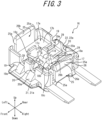
- FIG. 3 is an enlarged perspective view illustrating the first split housing 16 alone, omitting the relay contact 50.
- the configuration of the first split housing 16 will be described in detail with reference to FIG. 3 .
- An outer peripheral edge of one surface (a top surface in FIG. 3 ) in a thickness-direction of the first split housing 16 is formed by an outer peripheral wall 17.
- the inside of the outer peripheral wall 17 is configured as an inner peripheral recess 17a recessed stepwise from the top surface of the first split housing 16.
- the bottom surface of the inner peripheral recess 17a includes an inner peripheral first opposing surface 17b configured as a plane parallel to the top surface of the first split housing 16.
- the central portion located on the inner peripheral side of the inner peripheral first opposing surface 17b is configured as a first central recess 17c recessed stepwise from the inner peripheral first opposing surface 17b.
- the bottom surface of the first central recess 17c includes a first central opposing surface 17d configured as a plane parallel to the inner peripheral first opposing surface 17b.
- the first central recess 17c and the first central opposing surface 17d constitute a contact mounting groove 18.
- the contact mounting groove 18 includes a fixing portion 18a and a central projection 18b, which is located at the center of the fixing portion 18a with respect to the right-left direction and configured to narrow the front-rear direction width of the fixing portion 18a while separating the fixing portion 18a into a pair of portions in the right-left direction.
- Each of the bottom surfaces of the fixing portion 18a (the first central opposing surface 17d) is provided with a positioning protrusion 18c having a substantially cylindrical shape.
- the outer peripheral wall 17 of the first split housing 16 includes a pair of first cable mounting grooves 19 configured as cutouts linearly arranged on the front and rear sides of one of the fixing portions 18a.
- the outer peripheral wall 17 of the first split housing 16 also includes a pair of second cable mounting grooves 20 configured as cutouts linearly arranged on the front and rear sides of the other fixing portion 18a.
- the second cable mounting groove 20 is in parallel with the first cable mounting groove 19.
- Each of the first cable mounting grooves 19 and each of the second cable mounting grooves 20 have a semi-circular shape in a plan view.
- a pair of inclined surfaces 19a is provided inclining outward in the downward direction from the bottoms of the pair of first cable mounting grooves 19.
- a pair of inclined surfaces 20a is provided inclining outward in the downward direction from the bottoms of the pair of second cable mounting grooves 20.
- the front and rear surfaces of the outer peripheral wall 17 of the first split housing 16 are provided with cover portions 21 and 22, respectively.
- the cover portion 21 has a flat-plate shape extending in the front direction from under the inclined surfaces 19a and 20a
- the cover portion 22 has a flat-plate shape extending in the rear direction from under the inclined surfaces 19a and 20a.
- the opposing surface 21a of the cover portion 21 and the opposing surface 22a of the cover portion 22 are flush with the bottom of the inclined surfaces 19a and 20a.
- the right and left side surfaces of the outer peripheral wall 17 of the first split housing 16 are provided with a pair of first locking portions 25 having resiliency.
- a pair of recesses 25a is formed between each first locking portion 25 and the front and rear surfaces of the outer peripheral wall 17.
- Each first locking portion 25 is provided with a first locking protrusion 26 that protrudes outward from the side surface of the first split housing 16.
- the first locking protrusions 26 extend in the front-rear direction.
- Each first locking protrusion 26 includes an inclined surface 26a that is inclined to the outside of the first split housing 16 in the downward direction.
- Each of the pair of first locking portions 25 is provided with an inclined surface 26b that is formed on the top edge of the inner surface of each of the pair of first locking portions 25 and inclined to the inside of the first split housing 16 in the downward direction.
- Each pressing portion 29 includes a pair of ribs arranged in parallel with each other in the right-left direction and extending in the front-rear direction.
- the space between a pair of ribs in the right-left direction is substantially the same as the width of the first cable mounting groove 19 and the width of the second cable mounting groove 20 in the right-left direction.
- FIG. 4 is an enlarged perspective view of the second split housing 30 alone. The configuration of the second split housing 30 will be described in detail with reference to FIG. 4 .
- An outer peripheral edge of one surface (a top surface in FIG. 4 ) in a thickness-direction of the second split housing 30 is formed as a protrusion by an outer peripheral wall 31.
- the inside of the outer peripheral wall 31 is configured as an inner peripheral recess 31a that is recessed stepwise from the top edge of the outer peripheral wall 31.
- a bottom surface of the inner peripheral recess 31a includes an inner peripheral second opposing surface 31b configured as a flat plane parallel to the top surface of the second split housing 30.
- the inner peripheral second opposing surface 31b is provided with a cable pressing protrusion 32 that includes a pair of a first pressing groove 32a and a second pressing groove 32b having U-shapes in cross-sections arranged in the right-left direction.
- the cable pressing protrusion 32 includes a central protrusion 32c and protrusions 32d and 32e on the right side and the left side, respectively, of the central protrusion 32c.
- the first pressing groove 32a is formed between the central protrusion 32c and the protrusion 32d.
- the second pressing groove 32b is formed between the central protrusion 32c and the protrusion 32e.
- the second split housing 30 includes a cable supporting arm 35 protruding from the front surface of the second split housing 30 and a cable supporting arm 36 protruding from the rear surface thereof.
- the top surface of the cable supporting arm 35 includes a first cable holding groove 35a and a second cable holding groove 35b
- the top surface of the cable supporting arm 36 includes a first cable holding groove 36a and a second cable holding groove 36b.
- the cable supporting arm 35 located on the front side is provided with a pair of protruding members 37a spaced apart from each other in the right-left direction in the front end portion of the first cable holding groove 35a, and the cable supporting arm 36 located on the rear side is provided with a pair of protruding members 38a spaced apart from each another in the right-left direction in the rear end portion of the first cable holding groove 36a.
- the cable supporting arm 35 located on the front side is provided with a pair of protruding members 37b spaced apart from each other in the right-left direction in the front end portion of the second cable holding groove 35b
- the cable supporting arm 36 located on the rear side is provided with a pair of protruding members 38b spaced apart from each other in the right-left direction in the rear end portion of the second cable holding groove 36b.
- Each of the pair of protruding members 37a, the pair of protruding members 38a, the pair of protruding members 37b and the pair of protruding members 38b is elastically bent in the right-left direction and the spacing from its adjacent protrusion is changeable.
- Each of the pair of protruding members 37a and 37b includes a pair of claws opposing each other formed at the lower front end. Also, each of the pair of protruding members 38a and 38b includes a pair of claws opposing each other formed at the lower rear end.
- Each of the first cable holding grooves 35a and 36a and each of the second cable holding grooves 35b and 36b has a depth sufficient for insertion and retention (to accommodate) of the entire diameter of the first cable 60 and the second cable 65.
- the first cable holding grooves 35a and 36a include inclined surfaces 35e and 36e, respectively, which are inclined upward in the outward directions.
- portions of the first cable 60 corresponding to the inclined surface 35e of the first cable holding groove 35a and the inclined surface 36e of the first cable holding groove 36b are inclined obliquely in the up-down direction along the inclined surfaces 35e and 36e, as illustrated in FIG. 1 .
- the second cable holding grooves 35b and 36b include inclined surfaces 35f and 36f, respectively.
- the second cable 65 is inserted into and held by the second cable holding grooves 35b and 36b in a manner similar to the first cable 60.
- a pair of retainer protrusions 35c is provided to the first cable holding groove 35a in the vicinity of a top opening of a front end portion (on the opposing surfaces provided with the pair of protruding members 37a) and a pair of retainer protrusions 36c is provided to the first cable holding groove 36a in the vicinity of a top opening of a rear end portion (on the opposing surfaces provided with the pair of protruding members 38a).
- a pair of retainer protrusions 35d is provided to the second cable holding groove 35b in the vicinity of a top opening of a front end portion (on the opposing surfaces provided with the pair of protruding members 37b), and a pair of retainer protrusions 36d is provided to the second cable holding groove 36b in the vicinity of a top opening of a rear end portion (on the opposing surfaces provided with the pair of protruding members 38b).
- the retainer protrusions 35c and 36c allow insertion of the first cable 60 into the first cable holding grooves 35a and 36a
- the retainer protrusions 35d and 36d allow insertion of the second cable 65 into the second cable holding grooves 35b and 36b.
- each of the pair of protruding members 37a, the pair of protruding members 38a, the pair of protruding members 37b and the pair of protruding members 38b is bent so that the gaps therebetween (i.e., the gap between the pair of retainer protrusions 35c, the gap between the pair of retainer protrusions 36c, the gap between the pair of retainer protrusions 35d, and the gap between the pair of retainer protrusions 36d) are widened in the right-left direction.
- each of the pair of protruding members 37a, the pair of protruding members 38a, the pair of protruding members 37b and the pair of protruding members 38b is elastically bent in directions which narrow the space therebetween in the right-left direction.
- the pair of protruding members 37a and the pair of protruding members 38a allow, in a resisting manner, a cable-extending-direction movement of the first cable 60 inserted into the first cable holding grooves 35a and 36a.
- the pair of protruding members 37b and the pair of protruding members 38b allow, in a resisting manner, a cable-extending-direction movement of the second cable 65 inserted into the second cable holding grooves 35b and 36b.
- the pair of protruding members 37a and the pair of protruding members 38a function as a stopper configured to resist a force acting to remove the first cable 60 from the first cable holding grooves 35a and 36a and inhibit easy removal of the first cable 60, and allow removal of the first cable 60 upon application of an external force of a certain strength or greater.
- the pair of protruding members 37b and the pair of protruding members 38b function as a stopper configured to resist a force acting to remove the second cable 65 from the second cable holding grooves 35b and 36b and inhibit easy removal of the second cable 65, and allow removal of the second cable 65 upon application of an external force of a certain strength or greater.
- the right and left side surfaces of the outer peripheral wall 31 of the second split housing 30 include a pair of second locking portions 39.
- the pair of second locking portions 39 is formed on the inner surface of the second split housing 30.
- Each of the pair of second locking portions 39 includes a second locking protrusion 40 that protrudes inward from the side surface of the second split housing 30.
- Each of the second locking portions 39 includes a pair of projection walls 41 extending in the up-down direction at the front and rear ends of the respective second locking portions 39.
- Each of the second locking protrusions 40 has a substantially rectangular parallelepiped shape formed on the inner surface of the second split housing 30 and extends between the pair of projection walls 41. The second locking protrusions 40 extend in the front-rear direction.
- each pressing portion 44 includes a pair of ribs arranged in parallel with each other in the right-left direction and extending in the front-rear direction.
- the space between a pair of ribs in the right-left direction is substantially the same as the width of the first pressing groove 32a and the width of the second pressing groove 32b in the right-left direction.
- FIG. 5 is a perspective view illustrating the insulating housing 15 in its entirety, omitting the relay contact 50.
- the first split housing 16 and the second split housing 30 are coupled via the pair of first connecting portions 46 that is arranged in the front-rear direction and linearly extends from the first split housing 16, a pair of second connecting portions 47 that is arranged in the front-rear direction and linearly extends from the second split housing 30, and a pair of fold-facilitating portions 48.
- the fold-facilitating portions 48 couple the pair of first connecting portions 46 and the pair of second connecting portions 47.
- the pair of first connecting portions 46 and the pair of second connecting portions 47 are flushed with each other in the expanded state.
- the fold-facilitating portions 48 are thinner than the first connecting portion 46 and the second connecting portion 47 arranged in the front-rear direction, as illustrated in FIG. 2 and FIG. 5 .
- Each of the pair of first connecting portions 46 and the pair of second connecting portions 47 arranged in the front-rear direction can be (easily) folded at the fold-facilitating portions 48 that extend in the front-rear direction and serve as a folding line for valley-folding (i.e., in a folding manner to bring the first split housing 16 and the second split housing 30 close to each other) in FIG. 1 , FIG. 5 , and the like.
- the pair of first connecting portions 46 has flexural rigidity smaller than that of the pair of second connecting portions 47.
- Each of the first split housing 16, the first connecting portions 46, the fold-facilitating portions 48, the second connecting portions 47, and the second split housing 30 has strength (rigidity) sufficient to autonomously maintain the expanded state illustrated in FIG. 1 and FIG. 5 .
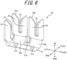
- FIG. 6 is a perspective view illustrating the relay contact 50 alone. A configuration of the relay contact 50 will be described in detail with reference to FIG. 6 .
- the relay contact 50 is formed by processing of a thin plate made of a copper alloy (e.g., phosphor bronze, beryllium copper, or titanium copper) or Corson copper alloy into a shape as illustrated in the figure by using a progressive die (stamping).
- the relay contact 50 is plated with copper-tin alloy or tin (or gold) after nickel plate undercoating.
- the relay contact 50 includes, in an integrated manner, a base 51 that has a plate-like shape and extends in the right-left direction, a pair of first cable press-contact members 52 each having a plate-like shape that protrudes from the front and rear edges on one side of the base 51 and extends in a direction vertical to the base 51, and a pair of second cable press-contact members 54 each having a plate-like shape that protrudes from the front and rear edges on the other side of the base 51 and extends in a direction vertical to the base 51.
- the base 51 includes a pair of positioning holes 51a having a circular shape in the right and left portions of the base 51.
- Each of the pair of first cable press-contact members 52 and each of the pair of second cable press-contact members 54 arranged in the front-rear direction includes a first press-contact groove 53 and a second press-contact groove 55, respectively, configured as slits linearly extending toward the base 51.
- Each of the pair of first press-contact grooves 53 includes, at the top opening thereof, a top end portion 52a having a substantially V-shape opening upward.
- Each of the pair of second press-contact grooves 55 includes, at the top opening thereof, a top end portion 54a having a substantially V-shape opening upward.
- the pair of first cable press-contact members 52 and the pair of second cable press-contact members 54 arranged in the front-rear direction are coupled to the base 51 via narrow portions (neck portions) 52b and 54b, respectively.
- the spaces between the opposing edges of the pair of first cable press-contact members 52 and the pair of second cable press-contact members 54 arranged in the right-left direction are narrower than those between the opposing edges of the narrow portions 52b and the narrow portions 54b.
- a space 51b is formed between the narrow portion 52b and the narrow portion 54b.
- No other members, such as an insulator, are provided between the pair of first cable press-contact members 52 and the pair of second cable press-contact members 54.
- the core wires 61 and 66 maintain the respective mechanical strengths, thereby reducing the likelihood that the core wires 61 and 66 are completely severed by tensile forces applied to the first cable 60 and the second cable 65. This can improve reliable contact between each of the first cable 60 and the second cable 65 and the relay contact 50.
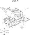
- FIG. 10 is a perspective view illustrating the insulating housing 15 loaded with the fillers 70 in the expanded state.
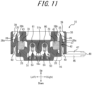
- FIG. 11 is a cross-sectional view illustrating the connector 10 loaded with the fillers 70 in the locked state corresponding to FIG. 9 .
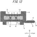
- FIG. 12 is a cross-sectional view illustrating the connector 10 loaded with the fillers 70 in the locked state taken along arrows XII-XII of FIG. 8 .
- the fillers 70 are placed on the inner peripheral first opposing surface 17b of the first split housing 16 and the inner peripheral second opposing surface 31b of the second split housing 30, respectively, as illustrated in FIG. 10 .
- the first filler 70a placed on the inner peripheral first opposing surface 17b of the first split housing 16 includes a bottom surface having a planar shape in substantial conformance with the inner peripheral first opposing surface 17b, and has a rectangular tubular shape surrounding the relay contact 50.
- the height of the first filler 70a is determined so that the first filler 70a and the second filler 70b are merged or adhered to each other when the first split housing 16 and the second split housing 30 are fitted together.
- the second filler 70b placed on the inner peripheral second opposing surface 31b of the second split housing 30 includes a bottom surface having a planar shape in substantial conformance with the inner peripheral second opposing surface 31b, and has a rectangular tubular shape surrounding the cable pressing protrusion 32.
- the height of the second filler 70b is determined so that the first filler 70a and the second filler 70b are merged or adhered to each other when the first split housing 16 and the second split housing 30 are fitted together.
- the first filler 70a and the second filler 70b are crushed to each other and are brought into a compressed state once. Thus they are brought in close contact with each other in a reliable manner.
- the fillers 70 include a material having merging properties
- the first filler 70a and the second filler 70b are integrated through a chemical reaction such as hydrogen bonding and the like.
- the fillers 70 include a material having adhesive properties
- the first filler 70a and the second filler 70b form a bonding surface and adhere to each other. In this manner, the fillers 70 seal the periphery of the relay contact 50.
- the first cable 60 and the second cable 65 extend outward from the relay contact 50 arranged inside the fillers 70. That is, the first cable 60 and the second cable 65 extend outward from the press-contact portions of the relay contact 50 in the front and rear directions.
- Each pressing portion 29 is arranged near the end portion of each cable along the right-left direction (the direction vertical to the fitting direction), and includes at least one rib that is provided, in a protruding manner, on an inner surface of the corresponding first split housing 16.
- Each pressing portion 29 presses the fillers 70 toward end portion of each cable along the right-left direction.
- Pressing portions 29 are arranged in parallel with each other near both end portions of each cable along the right-left direction, and each pressing portion 29 may include a pair of ribs provided, in a protruding manner, on the inner surface of the corresponding first split housing 16. In this case, the pressing portions 29 press the fillers 70 toward both end portions of each cable along the right-left direction.
- the pressing portions 29 are arranged along the right-left direction so that each cable is interposed therebetween, and press the fillers 70 toward both right and left end portions of each cable.
- the action of the pressing portions 29 and the pressing portions 44 allows the fillers 70 to surround, in a closely contact manner, the surface of the sheath 62 of the first cable 60 and the surface of the sheath 67 of the second cable 65 without interrupting electrical connection with the relay contact 50.
- the first split housing 16 and the second split housing 30 are fitted together, the first cable 60 and the second cable 65 are arranged in the first filler 70a and the second filler 70b in a cross-sectional view along the fitting direction, that is, the up-down direction.
- the first split housing 16 and the second split housing 30 include a pair of spaces 28 and a pair of spaces 43, respectively, for accommodating excessive portions of the fillers 70 ( FIG. 11 ).
- the spaces 28 and the spaces 43 are formed along the inner surfaces of the pair of first locking portions 25, and the spaces 28 are located under the fillers 70 while the spaces 43 are located above the fillers 70.
- the spaces 28 and the spaces 43 can absorb and store the excessive portions of the fillers 70 in the locked state. Consequently, the connector 10 can accommodate a difference between pressing forces applied to the first cable 60 and the second cable 65.
- the fillers 70 abut the inner surfaces of the pair of first locking portions 25 of the first split housing 16.
- Each of the engaging surfaces 27 of the first locking protrusion 26 and the second locking protrusion 40 are located, with respect to the up-down direction thereof, within the up-down direction width of the fillers 70, as illustrated in FIG. 11 .
- the surface of the second locking protrusion 40 abuts the outer surface of the first locking portion 25.
- Each of abutment surfaces 42 thus formed is substantially parallel to the inner surface of the first locking portion 25 abutting the fillers 70.
- the connector 10 can effectively prevent foreign matter such as water or dust from entering from outside.
- the connector 10 can adjust, by the pressing portions 29 and the pressing portions 44, the difference in surface pressure between each filler 70 caused by the difference in shape between the first split housing 16 and the second split housing 30. In this manner, the connector 10 can reliably merge or adhere the first filler 70a and the second filler 70b to each other.
- the connector 10 can sufficiently prevent foreign matter from entering from outside by the pressing portions 29 and the pressing portions 44 even in a state in which the first cable 60 and the second cable 65 are held by the connector 10.
- the fillers 70 are brought in close contact with each cable by being pressed by each pressing portion and deformed in accordance with the shape of each cable. In this manner, the waterproof properties of the connector 10 can be improved.
- the connector 10 can control a surface pressure of the fillers 70 with respect to each cable by the press by each pressing portion. In this manner, with the connector 10, the first filler 70a and the second filler 70b can be merged or adhered to each other in a reliable manner.
- the connector 10 can convert a fitting force acting when the first split housing 16 and the second split housing 30 are fitted together directly into a pressing force. In this manner, the surface pressure of fillers 70 with respect to each cable is improved, which allows the fillers 70 to be brought in close contact with each cable in more effective manner.
- each pressing portion presses the fillers 70 toward the end portions in the right-left direction of each cable by at least one rib shape
- the fillers 70 are brought in close contact with the ends of each cable in a reliable manner.
- a merging face or a bonding face between the first filler 70a and the second filler 70b is formed near the end portions in the right-left direction of each cable, a gap is easily formed near the end portions when the first split housing 16 and the second split housing 30 are fitted together.
- the connector 10 prevents formation of such gap by the above described pressing portions having a rib shape, and contributes to improve waterproof properties.
- Each pressing portion presses the fillers 70 toward the both right and left ends of each cable, and as a result the fillers are brought in close contact with the both right and left ends of each cable in a reliable manner.
- the fillers 70 can cover all over each cable without forming a gap between right and left end portions of each cable and the merging face or the bonding face between the first filler 70a and the second filler 70b.
- each pressing portion is arranged along the right-left direction so that each cable is interposed therebetween, thus in the locked state, each cable can be arranged near the center of each pressing portion in the right-left direction.
- the connector 10 presses the fillers 70 toward both right and left ends of each cable, and thus the center of each cable is guided to near the center of each pressing portion in the right-left direction. In this manner, the connector 10 can accommodate a difference between positions caused by the type of cable.
- the fillers 70 are pressed toward each cable along the up-down direction by the pressing portions 29 and pressing portions 44, and thus the entire circumference of each cable can be covered with the fillers 70 in more reliable manner.
- a pressing force can be multiplied by the pressing portions 29 and the pressing portions 44. In this manner, a total surface pressure of the fillers 70 with respect to each cable is improved, and the fillers 70 can be brought in close contact with each cable efficiently from both up and down directions.
- the fillers 70 are brought in close contact with the first cable 60 and the second cable 65, even if the first cable 60 and the second cable 65 are shaken and bent by an external force applied to the outside of the connector 10, transmission of action or stress caused by the bent to the press-contact portion with the relay contact 50 can be prevented. Consequently reliable contact can be maintained.
- the first locking portions 25 having resiliency are elastically deformed outward by an elastic force acting from the inside to the outside caused by the expansion or swelling of the fillers 70.
- the connector 10 includes the locking portions formed therein, the connector 10 enables stronger engagement between the first locking portion 25 and the second locking portion 39 by their outward elastic deformation. More specifically, because the engaging surfaces 27 of the first locking protrusions 26 and the second locking protrusions 40 are located within the up-down-direction width of the inner surface of the first locking portion 25 abutting the fillers 70, an expansion force or the like of the fillers 70 is efficiently converted into an engaging force.
- the connector 10 can further strengthen the close contact between the first split housing 16 and the second split housing 30. In this manner, even in a state in which an elastic force acts from the inside to the outside, the connector 10 can inhibit opening of the first split housing 16 and the second split housing 30. Consequently, the connector 10 can maintain the waterproof properties.
- the connector 10 can further suppress the opening between the first split housing 16 and the second split housing 30.
- the fillers 70 When the fillers 70 are loaded to each of inner surfaces of the first split housing 16 and the second split housing 30, the fillers 70 adhere to each other in the locked state. This adhesive force acts as a force resisting against the opening of the first split housing 16 and the second split housing 30 fitted together.
- the connector 10 includes the locking mechanism inside the first split housing 16 and the second split housing 30 fitted together, the outer peripheral wall 31 can be formed in a substantially planar shape with less unevenness or through holes. This enables the connector 10 to have improved waterproof properties and to prevent other foreign matters such as dust and oil from entering from outside.
- the connector 10 can increase an area of the engaging surfaces 27 and thus strengthen the engagement. Because the engaging surfaces 27 in the connector 10 are substantially horizontal as illustrated in FIG. 11 , the engaging force can be easily transmitted between the first locking protrusion 26 and the second locking protrusion 40. In this manner, the first locking protrusion 26 and the second locking protrusion 40 of the connector 10 can have larger widths than those of conventional locking portions formed externally. This further increases a locking force and strengthens the locking. Because the strengths of the first locking portion 25 and the second locking portion 39 themselves are also increased, the connector 10 can inhibit damages to the locking portions.
- the connector 10 can prevent the top end of the first locking portion 25 from being pressed into or scraping the fillers 70 when the first split housing 16 and the second split housing 30 are fitted together.
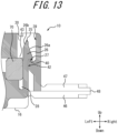
- FIG. 13 is an enlarged cross-sectional view illustrating an engaging portion between the first locking portion 25 and the second locking portion 39 corresponding to FIG. 11 according to a variation.
- each of the engaging surfaces 27 between the first locking protrusion 26 and the second locking protrusion 40 is a horizontal flat surface extending in the front-rear direction, as illustrated in FIG. 11 .
- this is not restrictive.
- each of the engaging surfaces 27 may be inclined downward toward the outside from the inside of the first split housing 16 and the second split housing 30 fitted together, as illustrated in FIG. 13 .
- This cross-sectional shape of the connector 10 can further reduce the likelihood of disengagement.
- first locking portions 25 are formed in the first split housing 16 and the second locking portions 39 are formed in the second split housing 30, this is not restrictive.
- the first locking portions 25 having resiliency may be formed in the second split housing 30 that does not include the relay contacts 50, and the second locking portions 39 may be formed in the first split housing 16 that includes the relay contact 50.
- the respective positions of the first locking portions 25 and the second locking portions 39 in the first split housing 16 and the second split housing 30 are not limited to the above description.
- the first locking portions 25 and the second locking portions 39 may be formed in any position as long as the first split housing 16 and the second split housing 30 can be fitted together and the locked state can be secured.
- first locking portions 25 and the second locking portions 39 include the first locking protrusions 26 and the second locking protrusions 40, respectively, which engage with each other and function as locking means.
- first locking portions 25 and the second locking portions 39 may have any locking means.
- the pair of retainer protrusions 35c and the pair of retainer protrusions 36c configured to prevent the first cable 60 from coming off are provided to the first cable holding grooves 35a and 36a, respectively, and the pair of retainer protrusions 35d and the pair of retainer protrusions 36d configured to prevent the second cable 65 from coming off are provided to the second cable holding grooves 35b and 36b, respectively, the retainer protrusions may be provided to each of the first pressing groove 32a and the second pressing groove 32b of the cable pressing protrusion 32.
- the relay contact 50 is configured to clamp the second cable 65
- the relay contact 50 may be configured to crimp the second cable 65 in an embodiment which does not form part of the invention as claimed.
- the second cable 65 is connected in a crimped manner to the relay contact 50 in advance and, in this state, the relay contact 50 is mounted in the first split housing 16.
- cable crimp terminals are formed in place of one of the pair of first press-contact grooves 53 and the pair of second press-contact grooves 55 of the relay contact 50.
- the second split housing 30 is provided with the cable supporting arm 35 or 36 corresponding to the remaining one of the press-contact grooves.
- the connector 10 may connect three or more cables together that are arranged in a direction orthogonal to or substantially orthogonal to the extending direction of the portions of the cables supported by the connector 10.
- a relay contact may include a set of three or more press-contact grooves (arranged in the right-left direction).
- a plurality of relay contacts may include the respective press-contact grooves, and at least one of the relay contacts includes two or more pairs of press-contact grooves, each of which is configured to clamp a cable (a core wire).
- first split housing 16 corresponds to the first fitting object and the second split housing 30 corresponds to the second fitting object.
- this is not restrictive, and the relationship may be opposite.
- each pressing portion is arranged along the up-down direction together with each cable, this is not restrictive, and it may be arranged in any position as far as it allows the fillers 70 to be brought in close contact with each cable.
- each pressing portion may be formed on either one of end portions in the right-left direction of the inner peripheral first opposing surface 17b and the inner peripheral second opposing surface 31b. In this case, each pressing portion presses the fillers 70 obliquely toward the center of each cable.
- each pressing portion includes a pair of ribs, this is not restrictive, and it may be provided as a flat-plate protrusion.
- the cross-sectional shape thereof is not limited to a substantially rectangular shape, and it may be any shape as far as it can press the fillers 70.
- each pressing portion may be provided as an inclined protrusion that gradually widens inwardly.
- Each pressing portion may include a plurality of ribs (but not a pair), or may include multiple pairs of ribs.
- each pressing portion 29 and each pressing portion 44 in the right-left direction are substantially the same, this is not restrictive, and the positions thereof in the right-left direction may be different from each other.
- pressing portions 29 and the pressing portions 44 are provided, in a protruding manner, to the first split housing 16 and the second split housing 30, respectively, this is not restrictive. In an embodiment which does not form part of the invention as claimed, pressing portions may be provided to only one of them in a protruding manner as far as the surface pressure of the fillers 70 can be controlled.
Landscapes
- Connector Housings Or Holding Contact Members (AREA)
- Details Of Connecting Devices For Male And Female Coupling (AREA)
- Connections By Means Of Piercing Elements, Nuts, Or Screws (AREA)
Claims (5)
- Ein Verbinder (10), umfassend:ein isolierendes Gehäuse (15), das ein erstes geteiltes Gehäuse (16), ein zweites geteiltes Gehäuse (30) und Verbindungsabschnitte (46, 47) in einer integral geformten Weise umfasst, wobei das erste geteilte Gehäuse (16) und das zweite geteilte Gehäuse (30) in der Lage sind, zusammengefügt und durch die Verbindungsabschnitte (46, 47) miteinander verbunden zu werden;Füllungen (70a, 70b), die in inneren Umfangsaussparungen (17a, 31a) vorgesehen sind, die an der Innenseite von äußeren Umfangswänden (17, 31) des ersten geteilten Gehäuses (16) bzw. des zweiten geteilten Gehäuses (30) ausgebildet sind;ein Kontakt (50), der an dem ersten geteilten Gehäuse (16) oder dem zweiten geteilten Gehäuse (30) angebracht ist und eine Druckkontaktnut (53, 55) aufweist und dazu eingerichtet ist, Kerndrähte (61, 66) von mindestens zwei Kabeln (60, 65) durch die Druckkontaktnut (53, 55) festzuklemmen, um die Kabel (60, 65) elektrisch miteinander zu verbinden;wobei in einem Zustand, in dem das erste geteilte Gehäuse (16) und das zweite geteilte Gehäuse (30) zusammengefügt sind, der Kontakt (50) von den Füllern (70a, 70b) umgeben ist;wobei die äußere Umfangswand (17) des ersten geteilten Gehäuses (16) mit einem Paar erster Verriegelungsabschnitte (25) versehen ist, die eine Elastizität aufweisen; undwobei die äußere Umfangswand (31) des zweiten geteilten Gehäuses (30) mit einem Paar zweiter Verriegelungsabschnitte (39) versehen ist; dadurch gekennzeichnet, dass der Verbinder (10) ferner Folgendes umfasst:einen Pressabschnitt (29, 44), der an jeder der Bodenflächen (17b, 31b) der inneren Umfangsaussparungen (17a, 31a) des ersten geteilten Gehäuses (16) und des zweiten geteilten Gehäuses (30) vorstehend vorgesehen ist;wobei jeder der Pressabschnitte (29, 44) eine entsprechende der Füllungen (70a, 70b) in Richtung einer anderen der Füllungen (70a, 70b) drückt, die in einem anderen geteilten Gehäuse vorgesehen ist, und die Füllungen (70a, 70b) so drückt, dass die Füllungen (70a, 70b) in engen Kontakt mit den Kabeln (60, 65) gebracht werden, wenn das erste geteilte Gehäuse (16) und das zweite geteilte Gehäuse (30) zusammengefügt werden;wobei in einem Zustand, in dem das erste geteilte Gehäuse (16) und das zweite geteilte Gehäuse (30) zusammengefügt sind, ein Paar erster und zweiter Räume (28, 43) entlang der Innenflächen des Paars erster Verriegelungsabschnitte (25) ausgebildet ist und die ersten Räume (28) unter den Füllungen (70) angeordnet sind, während die zweiten Räume (43) über den Füllungen (70) angeordnet sind; undwobei die ersten und zweiten Räume (28, 43) überschüssige Teile der Füllungen (70a, 70b) aufnehmen und speichern; wobeiin dem Zustand, in dem das erste geteilte Gehäuse (16) und das zweite geteilte Gehäuse (30) zusammengefügt sind, die Füllungen (70a, 70b) aneinander gepresst und in einen komprimierten Zustand gebracht werden, wobei die Füllungen (70a, 70b) ein Material mit Verschmelzeigenschaften umfassen und durch eine chemische Reaktion, wie Wasserstoffbindung, integriert sind.
- Der Verbinder (10) nach Anspruch 1, wobei der Pressabschnitt (29, 44) entlang einer Fügerichtung des ersten geteilten Gehäuses (16) und des zweiten geteilten Gehäuses (30) angeordnet ist, so dass die Füllungen (70a, 70b) zwischen dem Pressabschnitt (29, 44) und dem Kabel (60, 65) angeordnet sind, und die Füllungen (70a, 70b) entlang der Fügerichtung drückt.
- Der Verbinder (10) nach einem der Ansprüche 1 oder 2, wobei der Pressabschnitt (29, 44) in der Nähe eines Endabschnitts des Kabels (60, 65) entlang einer Richtung senkrecht zu einer Fügerichtung in dem Zustand angeordnet ist, in dem das erste geteilte Gehäuse (16) und das zweite geteilte Gehäuse (30) zusammengefügt sind, mindestens eine Rippe umfasst, die in einer vorstehenden Weise an einer Innenfläche eines entsprechenden geteilten Gehäuses (16, 30) vorgesehen ist, und die Füllungen (70a, 70b) in Richtung des Endabschnitts des Kabels (60, 65) entlang der Richtung senkrecht zur Fügerichtung drückt.
- Der Verbinder (10) nach Anspruch 3, wobei
mehrere der Pressabschnitte (29, 44) parallel zueinander in der Nähe beider Endabschnitte des Kabels (60, 65) entlang der Richtung senkrecht zur Fügerichtung angeordnet sind, wenn das erste geteilte Gehäuse (16) und das zweite geteilte Gehäuse (30) zusammengefügt sind, wobei jeder der Pressabschnitte (29, 44) mit mindestens einem Paar Rippen versehen ist, die an einer Innenfläche eines entsprechenden geteilten Gehäuses (16, 30) vorstehend vorgesehen sind, und die Füllungen (70a, 70b) in Richtung der beiden Endabschnitte des Kabels (60, 65) entlang der Richtung senkrecht zur Fügerichtung drücken. - Der Verbinder (10) nach einem der Ansprüche 1 bis 4, wobei der Verbinder (10) dazu eingerichtet ist, dass sich mindestens eines der Kabel (60, 65) von dem Kontakt (50), der innerhalb der Füllungen (70a, 70b) angeordnet ist, nach außen erstreckt, wenn das erste geteilte Gehäuse (16) und das zweite geteilte Gehäuse (30) zusammengefügt werden.
Applications Claiming Priority (2)
| Application Number | Priority Date | Filing Date | Title |
|---|---|---|---|
| JP2017056628A JP6466983B2 (ja) | 2017-03-22 | 2017-03-22 | コネクタ |
| PCT/JP2018/007946 WO2018173684A1 (ja) | 2017-03-22 | 2018-03-02 | コネクタ |
Publications (3)
| Publication Number | Publication Date |
|---|---|
| EP3605743A1 EP3605743A1 (de) | 2020-02-05 |
| EP3605743A4 EP3605743A4 (de) | 2020-11-18 |
| EP3605743B1 true EP3605743B1 (de) | 2025-04-02 |
Family
ID=63584290
Family Applications (1)
| Application Number | Title | Priority Date | Filing Date |
|---|---|---|---|
| EP18771895.2A Active EP3605743B1 (de) | 2017-03-22 | 2018-03-02 | Verbinder |
Country Status (6)
| Country | Link |
|---|---|
| US (1) | US11056802B2 (de) |
| EP (1) | EP3605743B1 (de) |
| JP (1) | JP6466983B2 (de) |
| KR (1) | KR102216099B1 (de) |
| CN (1) | CN110383584B (de) |
| WO (1) | WO2018173684A1 (de) |
Families Citing this family (1)
| Publication number | Priority date | Publication date | Assignee | Title |
|---|---|---|---|---|
| EP3642911A4 (de) * | 2017-06-20 | 2021-03-03 | Commscope Technologies LLC | Stromverbinder |
Citations (2)
| Publication number | Priority date | Publication date | Assignee | Title |
|---|---|---|---|---|
| JP3028988B2 (ja) * | 1992-02-05 | 2000-04-04 | トヨタ自動車株式会社 | コネクタ |
| EP3467955A1 (de) * | 2016-05-25 | 2019-04-10 | Kyocera Corporation | Abzweigverbinder |
Family Cites Families (24)
| Publication number | Priority date | Publication date | Assignee | Title |
|---|---|---|---|---|
| US3899236A (en) * | 1974-06-24 | 1975-08-12 | Amerace Corp | Electrical connector |
| US5147217A (en) * | 1991-06-18 | 1992-09-15 | General Motors Corporation | Electrical component package |
| JPH069065U (ja) * | 1992-07-06 | 1994-02-04 | 本田技研工業株式会社 | ワイヤハーネスの防水ジョイント構造 |
| JP2836463B2 (ja) * | 1993-10-26 | 1998-12-14 | 住友電装株式会社 | 圧接ジョイントコネクタ |
| JP3081760B2 (ja) * | 1993-11-10 | 2000-08-28 | 矢崎総業株式会社 | 防水保護カバー |
| JPH08306428A (ja) * | 1995-04-28 | 1996-11-22 | Fuji Hoon Seisakusho:Kk | 電線接続部品 |
| JP3028988U (ja) | 1996-03-13 | 1996-09-17 | ヤーマン株式会社 | 光脱毛装置 |
| JP2939740B1 (ja) * | 1998-03-17 | 1999-08-25 | 株式会社ニチフ端子工業 | コネクタとその水密方法 |
| JP2001076809A (ja) * | 1999-09-09 | 2001-03-23 | Sumitomo Wiring Syst Ltd | コネクタ |
| DE10142363A1 (de) | 2001-08-30 | 2003-03-27 | Delphi Tech Inc | Elektrischer Verbinder |
| US7141738B2 (en) | 2004-02-02 | 2006-11-28 | 3M Innovative Properties Company | Re-enterable splice enclosure |
| CN2833262Y (zh) * | 2005-10-20 | 2006-11-01 | 上海光华仪表有限公司 | 仪表调整装置的密封结构 |
| AR068931A1 (es) * | 2007-10-31 | 2009-12-16 | Detnet South Africa Pty Ltd | Un conector para detonador |
| US7686661B2 (en) * | 2008-07-31 | 2010-03-30 | Tyco Electronics Corporation | Connection enclosure assemblies, connector systems and methods for forming an enclosed connection between conductors |
| US7845990B2 (en) * | 2008-07-31 | 2010-12-07 | Tyco Electronics Corporation | Connection enclosure assemblies, connector systems and methods for forming an enclosed connection between conductors |
| JP5787864B2 (ja) * | 2012-12-06 | 2015-09-30 | 京セラコネクタプロダクツ株式会社 | 分岐コネクタ |
| JP2015022976A (ja) * | 2013-07-23 | 2015-02-02 | 矢崎総業株式会社 | コネクタ |
| CN204088733U (zh) * | 2014-09-25 | 2015-01-07 | 泰科电子(上海)有限公司 | 密封圈、连接器及电器盒 |
| CN204495870U (zh) * | 2015-02-06 | 2015-07-22 | 浙江南腾电气有限公司 | 新型电表箱 |
| JP5966041B1 (ja) * | 2015-03-27 | 2016-08-10 | 京セラコネクタプロダクツ株式会社 | 分岐コネクタ |
| CN107534245B (zh) * | 2015-09-14 | 2019-12-24 | 京瓷株式会社 | 分支连接器 |
| JP6514142B2 (ja) * | 2016-04-27 | 2019-05-15 | 京セラ株式会社 | 分岐コネクタ |
| JP6495216B2 (ja) * | 2016-05-25 | 2019-04-03 | 京セラ株式会社 | 分岐コネクタ |
| US10541478B1 (en) * | 2017-10-04 | 2020-01-21 | The Patent Store, Llc | Insulation displacement connector |
-
2017
- 2017-03-22 JP JP2017056628A patent/JP6466983B2/ja active Active
-
2018
- 2018-03-02 WO PCT/JP2018/007946 patent/WO2018173684A1/ja not_active Ceased
- 2018-03-02 CN CN201880016284.XA patent/CN110383584B/zh active Active
- 2018-03-02 EP EP18771895.2A patent/EP3605743B1/de active Active
- 2018-03-02 KR KR1020197026504A patent/KR102216099B1/ko active Active
- 2018-03-02 US US16/494,903 patent/US11056802B2/en active Active
Patent Citations (2)
| Publication number | Priority date | Publication date | Assignee | Title |
|---|---|---|---|---|
| JP3028988B2 (ja) * | 1992-02-05 | 2000-04-04 | トヨタ自動車株式会社 | コネクタ |
| EP3467955A1 (de) * | 2016-05-25 | 2019-04-10 | Kyocera Corporation | Abzweigverbinder |
Also Published As
| Publication number | Publication date |
|---|---|
| US11056802B2 (en) | 2021-07-06 |
| EP3605743A1 (de) | 2020-02-05 |
| CN110383584B (zh) | 2022-06-21 |
| KR102216099B1 (ko) | 2021-02-16 |
| KR20190117615A (ko) | 2019-10-16 |
| EP3605743A4 (de) | 2020-11-18 |
| US20200036110A1 (en) | 2020-01-30 |
| WO2018173684A1 (ja) | 2018-09-27 |
| CN110383584A (zh) | 2019-10-25 |
| JP6466983B2 (ja) | 2019-02-06 |
| JP2018160360A (ja) | 2018-10-11 |
Similar Documents
| Publication | Publication Date | Title |
|---|---|---|
| EP3644444A1 (de) | Verbinder | |
| US10741935B2 (en) | Branch connector | |
| EP3657603B1 (de) | Verbinder | |
| EP3605745A1 (de) | Verbinder | |
| EP3605742B1 (de) | Verbinder | |
| EP3605743B1 (de) | Verbinder | |
| US10797410B2 (en) | Connector | |
| EP3633793B1 (de) | Verpackung für elektrische verbinder | |
| WO2018173685A1 (ja) | コネクタ |
Legal Events
| Date | Code | Title | Description |
|---|---|---|---|
| STAA | Information on the status of an ep patent application or granted ep patent |
Free format text: STATUS: THE INTERNATIONAL PUBLICATION HAS BEEN MADE |
|
| PUAI | Public reference made under article 153(3) epc to a published international application that has entered the european phase |
Free format text: ORIGINAL CODE: 0009012 |
|
| STAA | Information on the status of an ep patent application or granted ep patent |
Free format text: STATUS: REQUEST FOR EXAMINATION WAS MADE |
|
| 17P | Request for examination filed |
Effective date: 20190919 |
|
| AK | Designated contracting states |
Kind code of ref document: A1 Designated state(s): AL AT BE BG CH CY CZ DE DK EE ES FI FR GB GR HR HU IE IS IT LI LT LU LV MC MK MT NL NO PL PT RO RS SE SI SK SM TR |
|
| AX | Request for extension of the european patent |
Extension state: BA ME |
|
| DAV | Request for validation of the european patent (deleted) | ||
| DAX | Request for extension of the european patent (deleted) | ||
| A4 | Supplementary search report drawn up and despatched |
Effective date: 20201020 |
|
| RIC1 | Information provided on ipc code assigned before grant |
Ipc: H01R 4/24 20180101ALI20201014BHEP Ipc: H01R 4/2433 20180101ALI20201014BHEP Ipc: H01R 13/50 20060101ALI20201014BHEP Ipc: H01R 4/70 20060101ALI20201014BHEP Ipc: H01R 13/52 20060101AFI20201014BHEP |
|
| STAA | Information on the status of an ep patent application or granted ep patent |
Free format text: STATUS: EXAMINATION IS IN PROGRESS |
|
| 17Q | First examination report despatched |
Effective date: 20220328 |
|
| P01 | Opt-out of the competence of the unified patent court (upc) registered |
Effective date: 20230505 |
|
| REG | Reference to a national code |
Ref country code: DE Free format text: PREVIOUS MAIN CLASS: H01R0013520000 Ipc: H01R0004700000 Ref country code: DE Ref legal event code: R079 Ref document number: 602018080730 Country of ref document: DE Free format text: PREVIOUS MAIN CLASS: H01R0013520000 Ipc: H01R0004700000 |
|
| GRAP | Despatch of communication of intention to grant a patent |
Free format text: ORIGINAL CODE: EPIDOSNIGR1 |
|
| STAA | Information on the status of an ep patent application or granted ep patent |
Free format text: STATUS: GRANT OF PATENT IS INTENDED |
|
| RIC1 | Information provided on ipc code assigned before grant |
Ipc: H01R 13/52 20060101ALN20241223BHEP Ipc: H01R 13/50 20060101ALN20241223BHEP Ipc: H01R 4/2433 20180101ALI20241223BHEP Ipc: H01R 4/70 20060101AFI20241223BHEP |
|
| RIC1 | Information provided on ipc code assigned before grant |
Ipc: H01R 13/52 20060101ALN20250109BHEP Ipc: H01R 13/50 20060101ALN20250109BHEP Ipc: H01R 4/2433 20180101ALI20250109BHEP Ipc: H01R 4/70 20060101AFI20250109BHEP |
|
| INTG | Intention to grant announced |
Effective date: 20250116 |
|
| GRAS | Grant fee paid |
Free format text: ORIGINAL CODE: EPIDOSNIGR3 |
|
| GRAA | (expected) grant |
Free format text: ORIGINAL CODE: 0009210 |
|
| STAA | Information on the status of an ep patent application or granted ep patent |
Free format text: STATUS: THE PATENT HAS BEEN GRANTED |
|
| AK | Designated contracting states |
Kind code of ref document: B1 Designated state(s): AL AT BE BG CH CY CZ DE DK EE ES FI FR GB GR HR HU IE IS IT LI LT LU LV MC MK MT NL NO PL PT RO RS SE SI SK SM TR |
|
| REG | Reference to a national code |
Ref country code: GB Ref legal event code: FG4D |
|
| REG | Reference to a national code |
Ref country code: CH Ref legal event code: EP |
|
| REG | Reference to a national code |
Ref country code: IE Ref legal event code: FG4D |
|
| REG | Reference to a national code |
Ref country code: DE Ref legal event code: R096 Ref document number: 602018080730 Country of ref document: DE |
|
| REG | Reference to a national code |
Ref country code: NL Ref legal event code: MP Effective date: 20250402 |
|
| PG25 | Lapsed in a contracting state [announced via postgrant information from national office to epo] |
Ref country code: NL Free format text: LAPSE BECAUSE OF FAILURE TO SUBMIT A TRANSLATION OF THE DESCRIPTION OR TO PAY THE FEE WITHIN THE PRESCRIBED TIME-LIMIT Effective date: 20250402 |
|
| REG | Reference to a national code |
Ref country code: AT Ref legal event code: MK05 Ref document number: 1782259 Country of ref document: AT Kind code of ref document: T Effective date: 20250402 |
|
| PG25 | Lapsed in a contracting state [announced via postgrant information from national office to epo] |
Ref country code: PT Free format text: LAPSE BECAUSE OF FAILURE TO SUBMIT A TRANSLATION OF THE DESCRIPTION OR TO PAY THE FEE WITHIN THE PRESCRIBED TIME-LIMIT Effective date: 20250804 Ref country code: FI Free format text: LAPSE BECAUSE OF FAILURE TO SUBMIT A TRANSLATION OF THE DESCRIPTION OR TO PAY THE FEE WITHIN THE PRESCRIBED TIME-LIMIT Effective date: 20250402 Ref country code: ES Free format text: LAPSE BECAUSE OF FAILURE TO SUBMIT A TRANSLATION OF THE DESCRIPTION OR TO PAY THE FEE WITHIN THE PRESCRIBED TIME-LIMIT Effective date: 20250402 |
|
| REG | Reference to a national code |
Ref country code: LT Ref legal event code: MG9D |
|
| PG25 | Lapsed in a contracting state [announced via postgrant information from national office to epo] |
Ref country code: GR Free format text: LAPSE BECAUSE OF FAILURE TO SUBMIT A TRANSLATION OF THE DESCRIPTION OR TO PAY THE FEE WITHIN THE PRESCRIBED TIME-LIMIT Effective date: 20250703 Ref country code: NO Free format text: LAPSE BECAUSE OF FAILURE TO SUBMIT A TRANSLATION OF THE DESCRIPTION OR TO PAY THE FEE WITHIN THE PRESCRIBED TIME-LIMIT Effective date: 20250702 |
|
| PG25 | Lapsed in a contracting state [announced via postgrant information from national office to epo] |
Ref country code: PL Free format text: LAPSE BECAUSE OF FAILURE TO SUBMIT A TRANSLATION OF THE DESCRIPTION OR TO PAY THE FEE WITHIN THE PRESCRIBED TIME-LIMIT Effective date: 20250402 |
|
| PG25 | Lapsed in a contracting state [announced via postgrant information from national office to epo] |
Ref country code: BG Free format text: LAPSE BECAUSE OF FAILURE TO SUBMIT A TRANSLATION OF THE DESCRIPTION OR TO PAY THE FEE WITHIN THE PRESCRIBED TIME-LIMIT Effective date: 20250402 |
|
| PG25 | Lapsed in a contracting state [announced via postgrant information from national office to epo] |
Ref country code: HR Free format text: LAPSE BECAUSE OF FAILURE TO SUBMIT A TRANSLATION OF THE DESCRIPTION OR TO PAY THE FEE WITHIN THE PRESCRIBED TIME-LIMIT Effective date: 20250402 |
|
| PG25 | Lapsed in a contracting state [announced via postgrant information from national office to epo] |
Ref country code: AT Free format text: LAPSE BECAUSE OF FAILURE TO SUBMIT A TRANSLATION OF THE DESCRIPTION OR TO PAY THE FEE WITHIN THE PRESCRIBED TIME-LIMIT Effective date: 20250402 |
|
| PG25 | Lapsed in a contracting state [announced via postgrant information from national office to epo] |
Ref country code: RS Free format text: LAPSE BECAUSE OF FAILURE TO SUBMIT A TRANSLATION OF THE DESCRIPTION OR TO PAY THE FEE WITHIN THE PRESCRIBED TIME-LIMIT Effective date: 20250702 |
|
| PG25 | Lapsed in a contracting state [announced via postgrant information from national office to epo] |
Ref country code: IS Free format text: LAPSE BECAUSE OF FAILURE TO SUBMIT A TRANSLATION OF THE DESCRIPTION OR TO PAY THE FEE WITHIN THE PRESCRIBED TIME-LIMIT Effective date: 20250802 |
|
| PG25 | Lapsed in a contracting state [announced via postgrant information from national office to epo] |
Ref country code: LV Free format text: LAPSE BECAUSE OF FAILURE TO SUBMIT A TRANSLATION OF THE DESCRIPTION OR TO PAY THE FEE WITHIN THE PRESCRIBED TIME-LIMIT Effective date: 20250402 |
|
| REG | Reference to a national code |
Ref country code: DE Ref legal event code: R097 Ref document number: 602018080730 Country of ref document: DE |
|
| PG25 | Lapsed in a contracting state [announced via postgrant information from national office to epo] |
Ref country code: SM Free format text: LAPSE BECAUSE OF FAILURE TO SUBMIT A TRANSLATION OF THE DESCRIPTION OR TO PAY THE FEE WITHIN THE PRESCRIBED TIME-LIMIT Effective date: 20250402 Ref country code: DK Free format text: LAPSE BECAUSE OF FAILURE TO SUBMIT A TRANSLATION OF THE DESCRIPTION OR TO PAY THE FEE WITHIN THE PRESCRIBED TIME-LIMIT Effective date: 20250402 |
|
| PG25 | Lapsed in a contracting state [announced via postgrant information from national office to epo] |
Ref country code: CZ Free format text: LAPSE BECAUSE OF FAILURE TO SUBMIT A TRANSLATION OF THE DESCRIPTION OR TO PAY THE FEE WITHIN THE PRESCRIBED TIME-LIMIT Effective date: 20250402 |
|
| PG25 | Lapsed in a contracting state [announced via postgrant information from national office to epo] |
Ref country code: EE Free format text: LAPSE BECAUSE OF FAILURE TO SUBMIT A TRANSLATION OF THE DESCRIPTION OR TO PAY THE FEE WITHIN THE PRESCRIBED TIME-LIMIT Effective date: 20250402 |
|
| PG25 | Lapsed in a contracting state [announced via postgrant information from national office to epo] |
Ref country code: RO Free format text: LAPSE BECAUSE OF FAILURE TO SUBMIT A TRANSLATION OF THE DESCRIPTION OR TO PAY THE FEE WITHIN THE PRESCRIBED TIME-LIMIT Effective date: 20250402 Ref country code: SK Free format text: LAPSE BECAUSE OF FAILURE TO SUBMIT A TRANSLATION OF THE DESCRIPTION OR TO PAY THE FEE WITHIN THE PRESCRIBED TIME-LIMIT Effective date: 20250402 |
|
| PG25 | Lapsed in a contracting state [announced via postgrant information from national office to epo] |
Ref country code: IT Free format text: LAPSE BECAUSE OF FAILURE TO SUBMIT A TRANSLATION OF THE DESCRIPTION OR TO PAY THE FEE WITHIN THE PRESCRIBED TIME-LIMIT Effective date: 20250402 |
|
| PLBE | No opposition filed within time limit |
Free format text: ORIGINAL CODE: 0009261 |
|
| STAA | Information on the status of an ep patent application or granted ep patent |
Free format text: STATUS: NO OPPOSITION FILED WITHIN TIME LIMIT |
|
| REG | Reference to a national code |
Ref country code: CH Ref legal event code: L10 Free format text: ST27 STATUS EVENT CODE: U-0-0-L10-L00 (AS PROVIDED BY THE NATIONAL OFFICE) Effective date: 20260211 |
|
| 26N | No opposition filed |
Effective date: 20260105 |
|
| PGFP | Annual fee paid to national office [announced via postgrant information from national office to epo] |
Ref country code: DE Payment date: 20260128 Year of fee payment: 9 |