EP3604036B1 - Lenkvorrichtung für ein fahrzeug sowie gassackmodul für eine solche lenkvorrichtung - Google Patents
Lenkvorrichtung für ein fahrzeug sowie gassackmodul für eine solche lenkvorrichtung Download PDFInfo
- Publication number
- EP3604036B1 EP3604036B1 EP19186570.8A EP19186570A EP3604036B1 EP 3604036 B1 EP3604036 B1 EP 3604036B1 EP 19186570 A EP19186570 A EP 19186570A EP 3604036 B1 EP3604036 B1 EP 3604036B1
- Authority
- EP
- European Patent Office
- Prior art keywords
- module
- pressure sensor
- steering device
- cover
- horn
- Prior art date
- Legal status (The legal status is an assumption and is not a legal conclusion. Google has not performed a legal analysis and makes no representation as to the accuracy of the status listed.)
- Active
Links
Images



Classifications
-
- B—PERFORMING OPERATIONS; TRANSPORTING
- B60—VEHICLES IN GENERAL
- B60Q—ARRANGEMENT OF SIGNALLING OR LIGHTING DEVICES, THE MOUNTING OR SUPPORTING THEREOF OR CIRCUITS THEREFOR, FOR VEHICLES IN GENERAL
- B60Q5/00—Arrangement or adaptation of acoustic signal devices
- B60Q5/001—Switches therefor
- B60Q5/003—Switches therefor mounted on the steering wheel
-
- B—PERFORMING OPERATIONS; TRANSPORTING
- B60—VEHICLES IN GENERAL
- B60R—VEHICLES, VEHICLE FITTINGS, OR VEHICLE PARTS, NOT OTHERWISE PROVIDED FOR
- B60R21/00—Arrangements or fittings on vehicles for protecting or preventing injuries to occupants or pedestrians in case of accidents or other traffic risks
- B60R21/02—Occupant safety arrangements or fittings, e.g. crash pads
- B60R21/16—Inflatable occupant restraints or confinements designed to inflate upon impact or impending impact, e.g. air bags
- B60R21/20—Arrangements for storing inflatable members in their non-use or deflated condition; Arrangement or mounting of air bag modules or components
- B60R21/203—Arrangements for storing inflatable members in their non-use or deflated condition; Arrangement or mounting of air bag modules or components in steering wheels or steering columns
Definitions
- the invention relates to a steering device for a vehicle and a gas bag module for such a steering device.
- Steering devices that can be rotated about a steering axis, such as steering wheels, are generally known from the prior art and often have a cover on the occupant side for triggering a horn signal.
- This cover is usually the module cap of a gas bag module, which can be shifted or tilted by axial pressure against a spring force until two originally spaced horn contacts touch each other and generate a horn signal.
- the object of the invention is to create a steering device and / or a gas bag module for a steering device with a technically particularly simple and functionally reliable horn signal triggering, the steering device also preferably having particularly small gaps or, ideally, even a gap-free transition between the cover for triggering a horn signal and a steering wheel surface surrounding the cover.
- a steering device for a vehicle with a steering axis about which the steering device is rotatable, a cover on the occupant side in the installed state of the steering device for triggering a horn signal, an air-filled chamber adjoining the cover, a with the pressure sensor connected to the chamber for detecting pressure fluctuations in the chamber, and an electronic control unit electrically connected to the pressure sensor for activating a vehicle horn as a function of the detected pressure fluctuations.
- the invention is initially based generally on the knowledge that pressure fluctuations occurring when the vehicle horn is activated can be detected by a pressure sensor and used to trigger a horn signal.
- a conventional, technically complex horn mechanism with horn contacts mounted movably relative to one another can advantageously be replaced by a simple and compact pressure sensor.
- the pressure sensor is preferably a piezoresistive pressure sensor which changes its electrical resistance when there is a change in pressure and thus falls under the group of inexpensive to manufacture passive pressure sensors. Piezoresistive pressure sensors are also particularly advantageous for use in a steering device because of their high sensitivity, since no major displacements, tilting or material deformations of the cover are necessary to trigger a horn signal.
- the pressure sensor already detects pressure waves in the chamber caused by an external impact on the cover, the cover having a maximum axial deformation of less than 1 mm in the event of such a horn-triggering impact.
- a displaceable or tiltable mounting of the cover is not necessary in this case to activate the vehicle horn.
- the deformation caused by bumping or knocking on the cover is also minimal and not even perceptible as a deformation for the occupant.
- no static pressure is built up in the chamber due to the external impact or impact on the cover, but merely a pressure wave or shock wave which can be detected by the pressure sensor.
- a steering device with a particularly compact design results in the axial direction.
- the axial dimension of the air-filled chamber defined for example by a distance between the cover and the folded gas bag of a gas bag module, only has to be so large that that the pressure wave passes from the location of the external impact through the chamber to the pressure sensor and can be reliably detected by this.
- the horn signal can thus be varied via the electronic control unit as a function of the force or energy applied by the vehicle occupant. For example, a light knock on the cover could lead to a rather quiet and / or short horn signal, while a strong blow on the cover activates a rather loud and / or long horn signal.
- a connecting element in particular a connecting pipe or a connecting hose, can be provided between the pressure sensor and the chamber.
- the signal strength of the pressure wave can be improved via such a connecting element so that pressure fluctuations can be better and more reliably detected. If the respective framework conditions of the steering device permit, the pressure sensor protrudes directly into the chamber, so that a connecting element can be dispensed with.
- the steering device comprises a gas bag module for restraining a vehicle occupant, the cover for triggering the horn signal being a module cap of the gas bag module.
- the activation of the vehicle horn by means of a pressure sensor can consequently also be implemented in the case of particularly advantageous steering devices with an integrated gas bag module without any problems and without additional effort.
- a gas bag module for a steering device described above with a pressure sensor for detecting pressure fluctuations, a folded gas bag to restrain an occupant, and a module housing in which the folded gas bag is accommodated
- the module housing having a housing base , has a circumferential wall made in one piece with the housing base and a module cap on the occupant side, an air-filled chamber being formed between the module cap and the folded gas bag, the pressure sensor being in connection with the air-filled chamber and axially adjacent to the module cap and radially adjacent to the circumferential wall of the module housing is arranged, and wherein the pressure sensor detects pressure waves in the chamber caused by an external impact on the cover, the cover has a maximum axial deformation of less than 1 mm in the case of such a shock that triggers the horn signal.
- the complete assembly for activating the vehicle horn can be integrated into the gas bag module and preassembled on the gas bag module. This considerably simplifies the construction of the rest of the steering device, since no horn-related components or assembly steps are necessary outside the gas bag module.
- a connection for data and / or power transmission then only needs to be established.
- the pressure sensor is very close to or even at least partially in the air-filled chamber and can thus receive pressure signals, in particular pressure waves, particularly well and reliably.
- the pressure sensor or the entire horn module can be exchanged quickly and easily, for example in the event of a defect.
- a housing pocket for receiving the pressure sensor is molded onto the peripheral wall of the module housing.
- the pressure sensor is protected after it has been fixed in the housing pocket and can therefore not be damaged when the gas bag module is transported or when it is installed on the steering device.
- the housing pocket is molded onto the module cap of the module housing.
- the pressure sensor and the electronic control unit can in particular form a prefabricated horn module, this prefabricated horn module preferably being inserted into the housing pocket and fixed, in particular latched, in its inserted position on the module housing.
- this prefabricated horn module preferably being inserted into the housing pocket and fixed, in particular latched, in its inserted position on the module housing.
- the Figure 1 shows a section through an airbag module 10 for a steering device 12, with a pressure sensor 14 for detecting pressure fluctuations, a folded airbag 16 for restraining a vehicle occupant, a gas generator 17 for inflating the airbag 16, and a module housing 18 in which the folded airbag 16 is recorded.
- the module housing 18 has a housing base 20, a peripheral wall 22 made in one piece with the housing base 20 and a separate module cap 24 on the occupant side, an air-filled chamber 26 being formed between the module cap 24 and the folded gas bag 16, and the pressure sensor 14 with the chamber 26 is in flow connection and is arranged axially adjacent to the module cap 24 and radially adjacent to the peripheral wall 22 of the module housing 18.
- the gas bag module 10 is used in a steering device 12 of a motor vehicle, as exemplified in FIG Figure 2 is shown.
- the steering device 12 is designed here as a steering wheel and comprises a steering axis A about which the steering device 12 can be rotated, a cover 28 on the occupant side for triggering a horn signal, an air-filled chamber 26 adjoining the cover 28, and one in communication with the chamber 26
- Pressure sensor 14 for detecting pressure fluctuations in the chamber 26, as well as an electronic control unit 30 electrically connected to the pressure sensor 14 for activating an in Figure 1 schematically indicated vehicle horn 32 as a function of the detected pressure fluctuations.
- the steering device 12 can be designed without an airbag module 10 arranged in the hub area.
- the cover 28 is then, for example, merely a cladding for a skeleton of the steering device 12 or for electronic components arranged in the steering device 12.
- Gaps 34 indicated by dashed lines are no longer necessary for the function of the vehicle horn 32, which can be activated by a pressure sensor 14.
- gaps 34 can also be provided on a side of the steering device 12 facing the vehicle occupant, the position of which can be freely selected and the gap width of which can be particularly small.
- the cover 28 merges into a steering device cladding without a gap or extends over the entire side of the steering device 12 facing the vehicle occupant.
- the steering device 12 comprises an in Figure 1
- the gas bag module 10 is a prefabricated structural unit (see Figure 6 ), which is attached to the steering device 12 after the steering device 12 has been installed in the vehicle, a plurality of gaps 34 are created between the module cap 24 and a surface of the steering device 12 surrounding the module cap 24, as shown in FIG Figure 2 are indicated by dashed lines.
- a gap width of this gap 34 can, however, be reduced to a minimum predetermined by the dimensional tolerances of the components, since the gaps 34 are irrelevant for the proper functioning of the vehicle horn 32.
- the module cap 24 extends in the radial direction far beyond the actual gas bag module 10 and can at least partially cover or clad spokes 36 and / or a rim 38 of the steering device 12.
- a steering device 12 can be implemented in which at least one front side of the steering device 12 facing the vehicle occupant is designed without any gaps.
- the pressure sensor 14 is a piezoresistive pressure sensor 14 and consequently has a particularly high sensitivity.
- the pressure sensor records accordingly 14 already pressure waves in the chamber 26, which are only caused by an external impact or a knock on the cover 28.
- the cover 28 is deformed by less than 1 mm in the axial direction in the event of such an impact from the vehicle occupant which is sufficient to activate the vehicle horn 32.
- an axial distance d from the folded gas bag 16 can be kept very small, which advantageously contributes to a particularly low overall axial height of the gas bag module 10.
- the distance d only has to be chosen so large that the pressure wave from the location of the external impact passes through the chamber 26 to the pressure sensor 14 and can be reliably detected by this.
- the electronic control unit 30 specifically comprises a printed circuit board 42, which ensures, for example, an energy supply for the horn module 40, establishes data transmission to the central vehicle electronics and is connected to electronic components and circuits such as a microcontroller or filter.
- a housing pocket 44 for receiving the horn module 40 is molded onto the peripheral wall 22 of the module housing 18.
- the prefabricated horn module 40 is inserted in the axial direction into the housing pocket 44 and in its inserted position ( Figure 5 ) fixed on the module housing 18, in particular locked.
- the horn module 40 can be mounted quickly and easily on the gas bag module 10, specifically on the module housing 18 of the gas bag module 10 and, if necessary, can also be exchanged without any problems.
- the horn module 40 in the housing pocket 44 is well protected from any damage during transport or installation of the gas bag module 10.
- the lateral arrangement of the horn module 40 on the peripheral wall 22 of the module housing 18 also contributes in an advantageous manner to a particularly low overall axial height of the gas bag module 10.
- the housing pocket 44 can also be molded onto the module cap 24 instead of the circumferential wall 22, which is embodied in one piece with the housing base 20.
- the module cap 24 is finally pushed on axially so that the gas bag module 10 has an in Figure 6 shown, prefabricated structural unit forms.
- the gas bag module 10 When assembling the gas bag module 10 on the steering device 12, only a connection of the horn module 40 for data and / or power transmission then has to be established, for example via a plug connector 46.
- the module cap 24 has according to the Figures 5 and 6 a cap circumferential wall 48, and a cap end wall 48 which is embodied in one piece with the cap circumferential wall 48 and which faces a vehicle occupant when the gas bag module 10 is installed.
- a corresponding bulge 52 is provided on the cap peripheral wall 48 in the area of the housing pocket 44 so that the pressure sensor 14 projects directly into the air-filled chamber 26 and can detect pressure fluctuations in the chamber 26 particularly well and reliably.
- the cap end wall 48 projects radially beyond the cap circumferential wall 48 and protrudes at the edge.
- the pressure sensor 14 does not require a static change in pressure in the chamber 26 to trigger a horn signal, but detects pressure waves that result from impacts on the cover 28, a signal is triggered even if the impact occurs at the edge-side protrusion of the cap end wall 48, i.e. radially takes place outside the chamber 26.
- Such a shock excitation of the module cap 24 also generates a pressure wave in the chamber 26, which the piezo-resistive pressure sensor 14 detects.
- the necessary actuation force for activating the vehicle horn 32 can be slightly increased and / or the reliability of the signal triggering can be impaired somewhat.
- the Figure 7 shows a further embodiment of the gas bag module 10, this embodiment only differing from the gas bag module 10 described above in that a connecting element 54, in particular a connecting pipe or a connecting hose, is provided between the pressure sensor 14 and the chamber 26. Especially in the case of an angled connection or a large distance between the cover 28 and the pressure sensor 14, the detection of the pressure fluctuations by the pressure sensor 14 can be improved via such a connecting element 54.
- a connecting element 54 in particular a connecting pipe or a connecting hose
- FIG. 4 shows a further embodiment of the gas bag module 10 or of the steering device 12, which differs from the previously based on FIG Figures 1 to 7
- the described embodiments differ only in that the pressure sensor 14 and the electronic control unit 30 do not have a horn module 40 according to FIG Figure 3 form.
- the pressure sensor 14 is received in the housing pocket 44 and has an electrical connection 56 to an electronic control unit 30, which is arranged outside the housing pocket 44.
- the electronic control unit 30 is arranged outside the gas bag module 10 in the area of a hub 58 of the steering device 12 and is only connected to the pressure sensor 14 via a connector when the gas bag module 10 is mounted on the steering device 12, analogous to Figure 6 .
- relocating the electronic control unit 30 makes it possible to make the gas bag module 10 even more compact.
- the electronic control unit 30 for processing the data of the pressure sensor 14 can then be integrated into a control unit, which is usually provided in the steering device 12 anyway, for controlling various switching functions in the area of the spokes 36 and / or the rim 38, so that the displacement of the electronic control unit 30 no significant additional space requirement arises in the area of the hub 58.
Landscapes
- Engineering & Computer Science (AREA)
- Mechanical Engineering (AREA)
- Physics & Mathematics (AREA)
- Acoustics & Sound (AREA)
- Air Bags (AREA)
Description
- Die Erfindung betrifft eine Lenkvorrichtung für ein Fahrzeug sowie ein Gassackmodul für eine solche Lenkvorrichtung.
- Um eine Lenkachse drehbare Lenkvorrichtungen wie zum Beispiel Lenkräder sind aus dem Stand der Technik allgemein bekannt und weisen insassenseitig häufig eine Abdeckung zum Auslösen eines Hupensignals auf. Diese Abdeckung ist dabei in der Regel die Modulkappe eines Gassackmoduls, welche durch axialen Druck entgegen einer Federkraft verschoben oder verkippt werden kann, bis zwei ursprünglich beabstandete Hupenkontakte einander berühren und ein Hupensignal erzeugen.
- Um bei einer Hupenbetätigung die notwendige Verschiebung oder Verkippung der Abdeckung zu gewährleisten sind dabei unerwünscht große Spaltmaße zu der die Abdeckung umgebenden Lenkradoberfläche erforderlich. Diese Spalte sind zum einen optisch störend und zum anderen hinsichtlich Verschmutzung bzw. Reinigung problematisch. Ferner ist der oben beschriebene, herkömmliche Hupenmechanismus mit mehreren in Umfangsrichtung verteilten Hupenkontakt-Paaren und vorgespannter Kipp- oder Gleitlagerung insgesamt technisch aufwendig und teuer.
- Aus der
US 5,931,494 A ist bereits eine gattungsgemäße Lenkvorrichtung sowie ein gattungsgemäßes Gassackmodul bekannt, mit einer verformbaren Modulabdeckung, welche an eine weitgehend luftdicht abgeschlossene Kammer angrenzt, wobei in der Kammer ein Sensor angeordnet ist. Durch Ausüben eines Drucks auf die Modulabdeckung wird diese deformiert und folglich das Volumen der Kammer verringert, sodass ein Kammerinnendruck ansteigt. Der Sensor erfasst diesen statischen Druckanstieg und übermittelt daraufhin ein Signal zur Auslösung der Fahrzeughupe an eine elektronische Steuereinheit. - Aufgabe der Erfindung ist es, eine Lenkvorrichtung und/oder ein Gassackmodul für eine Lenkvorrichtung zu schaffen, mit einer technisch besonders einfachen und funktionssicheren Hupsignalauslösung, wobei die Lenkvorrichtung darüber hinaus vorzugsweise besonders geringe Spaltmaße oder idealerweise sogar einen spaltfreien Übergang zwischen der Abdeckung zum Auslösen eines Hupensignals und einer die Abdeckung umgebenden Lenkradoberfläche aufweist.
- Erfindungsgemäß wird diese Aufgabe durch eine Lenkvorrichtung für ein Fahrzeug gemäß Anspruch 1 gelöst , mit einer Lenkachse, um welche die Lenkvorrichtung drehbar ist, einer im eingebauten Zustand der Lenkvorrichtung insassenseitigen Abdeckung zum Auslösen eines Hupensignals, einer an die Abdeckung angrenzenden, luftgefüllten Kammer, einem mit der Kammer in Verbindung stehenden Drucksensor zur Erfassung von Druckschwankungen in der Kammer, und einer mit dem Drucksensor elektrisch verbundenen, elektronischen Steuereinheit zur Aktivierung einer Fahrzeughupe in Abhängigkeit der erfassten Druckschwankungen.
- Die Erfindung beruht zunächst allgemein auf der Erkenntnis, dass bei einer Aktivierung der Fahrzeughupe auftretende Druckschwankungen von einem Drucksensor erfasst und zur Auslösung eines Hupensignals genutzt werden können. Somit lässt sich ein herkömmlicher, technisch aufwendiger Hupenmechanismus mit relativ zueinander beweglich gelagerten Hupenkontakten in vorteilhafter Weise durch einen einfachen und kompakten Drucksensor ersetzen.
- Der Drucksensor ist dabei vorzugsweise ein piezoresistiver Drucksensor, der bei einer Druckänderung seinen elektrischen Widerstand ändert und damit unter die Gruppe der kostengünstig herstellbaren Passivdrucksensoren fällt. Für die Anwendung in einer Lenkvorrichtung sind piezoresistive Drucksensoren auch aufgrund ihrer hohen Empfindlichkeit besonders vorteilhaft, da zur Auslösung eines Hupensignals keine größeren Verschiebungen, Verkippungen oder Materialverformungen der Abdeckung notwendig sind.
- Erfindungsgemäß erfasst der Drucksensor bereits durch einen äußeren Stoß auf die Abdeckung hervorgerufene Druckwellen in der Kammer, wobei die Abdeckung bei einem solchen hupsignalauslösenden Stoß eine maximale axiale Verformung von weniger als 1 mm aufweist. Eine verschiebliche oder verkippbare Lagerung der Abdeckung ist in diesem Fall für eine Aktivierung der Fahrzeughupe nicht notwendig. Auch die durch das Stoßen oder Klopfen auf die Abdeckung hervorgerufene Verformung ist minimal und für den Insassen gar nicht als Verformung wahrnehmbar. Durch den äußeren Stoß oder Schlag auf die Abdeckung wird dementsprechend in der Kammer auch kein statischer Druck aufgebaut, sondern lediglich eine Druck- oder Stoßwelle erzeugt, welche vom Drucksensor erfassbar ist. Da folglich kein Raum für eine nennenswerte axiale Verformung der Abdeckung vorgesehen werden muss, ergibt sich in axialer Richtung eine besonders kompakt bauende Lenkvorrichtung. Die beispielsweise durch einen Abstand zwischen der Abdeckung und dem gefalteten Gassack eines Gassackmoduls definierte axiale Abmessung der luftgefüllten Kammer muss lediglich so groß sein, dass die Druckwelle vom Ort des äußeren Stoßes durch die Kammer bis zum Drucksensor gelangt und von diesem zuverlässig erfasst werden kann.
- Aufgrund der hohen Empfindlichkeit des Drucksensors kann über die erfasste Druckschwankung bzw. Druckwelle sogar auf die Stärke des äußeren Stoßes rückgeschlossen werden. Somit lässt sich über die elektronische Steuereinheit das Hupsignal abhängig von der durch den Fahrzeuginsassen aufgebrachten Kraft oder Energie variieren. Beispielsweise könnte ein leichtes Klopfen auf die Abdeckung zu einem eher leisen und/oder kurzen Hupsignal führen, während ein kräftiger Schlag auf die Abdeckung ein eher lautes und/oder langes Hupsignal aktiviert.
- In manchen Ausführungsformen der Lenkvorrichtung kann zwischen dem Drucksensor und der Kammer ein Verbindungselement, insbesondere ein Verbindungsrohr oder ein Verbindungsschlauch, vorgesehen sein. Je nach Position und Ausrichtung des Drucksensors lässt sich über ein solches Verbindungselement die Signalstärke der Druckwelle verbessern, sodass Druckschwankungen besser und zuverlässiger erfassbar sind. Sofern es die jeweiligen Rahmenbedingungen der Lenkvorrichtung zulassen, ragt der Drucksensor jedoch unmittelbar in die Kammer hinein, sodass auf ein Verbindungselement verzichtet werden kann.
- Gemäß einer Ausführungsform umfasst die Lenkvorrichtung ein Gassackmodul zur Rückhaltung eines Fahrzeuginsassen, wobei die Abdeckung zum Auslösen des Hupensignals eine Modulkappe des Gassackmoduls ist. Die Aktivierung der Fahrzeughupe mittels eines Drucksensors lässt sich folglich auch bei besonders vorteilhaften Lenkvorrichtungen mit integriertem Gassackmodul problemlos und ohne Mehraufwand realisieren.
- Erfindungsgemäß wird die obengenannte technische Aufgabe auch gelöst durch ein Gassackmodul für eine zuvor beschriebene Lenkvorrichtung, mit einem Drucksensor zur Erfassung von Druckschwankungen, einem gefalteten Gassack zur Rückhaltung eines Insassen, sowie einem Modulgehäuse, in dem der gefaltete Gassack aufgenommen ist, wobei das Modulgehäuse einen Gehäuseboden, eine mit dem Gehäuseboden einstückig ausgeführte Umfangswand und insassenseitig eine Modulkappe aufweist, wobei zwischen der Modulkappe und dem gefalteten Gassack eine luftgefüllte Kammer gebildet ist, wobei der Drucksensor mit der luftgefüllten Kammer in Verbindung steht sowie axial angrenzend an die Modulkappe und radial angrenzend an die Umfangswand des Modulgehäuses angeordnet ist, und wobei der Drucksensor durch einen äußeren Stoß auf die Abdeckung hervorgerufene Druckwellen in der Kammer erfasst, wobei die Abdeckung bei einem solchen hupsignalauslösenden Stoß eine maximale axiale Verformung von weniger als 1 mm aufweist.
- Auf diese Weise lässt sich die komplette Baugruppe zum Aktivieren der Fahrzeughupe in das Gassackmodul integrieren und am Gassackmodul vormontieren. Dies vereinfacht die Konstruktion der übrigen Lenkvorrichtung erheblich, da außerhalb des Gassackmoduls keine hupenbezogenen Bauteile oder Montageschritte notwendig sind. Bei der Montage des Gassackmoduls an der Lenkvorrichtung muss dann lediglich noch eine Verbindung zur Daten- und/oder Stromübertragung hergestellt werden. Durch die Positionierung radial angrenzend an die Umfangswand des Modulgehäuses und axial angrenzend an die Modulkappe befindet sich der Drucksensor sehr nah an oder sogar zumindest teilweise in der luftgefüllten Kammer und kann somit Drucksignale, insbesondere Druckwellen, besonders gut und zuverlässig empfangen. Ferner lässt sich infolge der seitlichen Anordnung am Modulgehäuse der Drucksensor bzw. das gesamte Hupenmodul schnell und einfach austauschen, beispielsweise bei einem Defekt.
- Gemäß einer Ausführungsform des Gassackmoduls ist an die Umfangswand des Modulgehäuses eine Gehäusetasche zur Aufnahme des Drucksensors angeformt. Der Drucksensor ist nach seiner Fixierung in der Gehäusetasche geschützt und kann somit bei einem Transport des Gassackmoduls oder bei dessen Montage an der Lenkvorrichtung nicht beschädigt werden. Alternativ ist auch denkbar, dass die Gehäusetasche an die Modulkappe des Modulgehäuses angeformt ist.
- Der Drucksensor und die elektronische Steuereinheit können insbesondere ein vorgefertigtes Hupenmodul bilden, wobei dieses vorgefertigte Hupenmodul vorzugsweise in die Gehäusetasche eingesteckt und in seiner eingesteckten Position am Modulgehäuse fixiert, insbesondere verrastet ist. Dadurch lässt sich die gesamte Baugruppe zur Aktivierung einer Fahrzeughupe als kompaktes Hupenmodul mit minimalem Montageaufwand in das Gassackmodul integrieren.
- Weitere Merkmale und Vorteile der Erfindung ergeben sich aus der nachfolgenden Beschreibung bevorzugter Ausführungsformen unter Bezugnahme auf die Zeichnungen. In diesen zeigt:
-
Figur 1 eine schematische Schnittansicht eines erfindungsgemäßen Gassackmoduls für eine erfindungsgemäße Lenkvorrichtung; -
Figur 2 eine Draufsicht einer erfindungsgemäßen Lenkvorrichtung; -
Figur 3 eine perspektivische Detailansicht eines Hupenmoduls mit Drucksensor; -
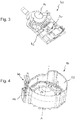
Figur 4 das Hupenmodul gemäßFigur 3 bei der Montage an einem Modulgehäuse eines erfindungsgemäßen Gassackmoduls; -
Figur 5 das Modulgehäuse gemäßFigur 4 mit fixiertem Hupenmodul bei der Montage einer Modulkappe; -
Figur 6 eine perspektivische Ansicht des vollständig zusammengesetzten Gassackmoduls beim Anschließen des Hupenmoduls; -
Figur 7 ein schematisches Schnittdetail eines erfindungsgemäßen Gassackmoduls im Bereich des Drucksensors gemäß einer Ausführungsvariante; und -
Figur 8 ein schematisches Schnittdetail einer erfindungsgemäßen Lenkvorrichtung im Bereich des Drucksensors gemäß einer weiteren Ausführungsvariante. - Die
Figur 1 zeigt einen Schnitt durch ein Gassackmodul 10 für eine Lenkvorrichtung 12, mit einem Drucksensor 14 zur Erfassung von Druckschwankungen, einem gefalteten Gassack 16 zur Rückhaltung eines Fahrzeuginsassen, einem Gasgenerator 17 zum Aufblasen des Gassacks 16, sowie einem Modulgehäuse 18, in dem der gefaltete Gassack 16 aufgenommen ist. Das Modulgehäuse 18 weist einen Gehäuseboden 20, eine mit dem Gehäuseboden 20 einstückig ausgeführte Umfangswand 22 und insassenseitig eine separate Modulkappe 24 auf, wobei zwischen der Modulkappe 24 und dem gefalteten Gassack 16 eine luftgefüllte Kammer 26 gebildet ist, und wobei der Drucksensor 14 mit der Kammer 26 in Strömungsverbindung steht sowie axial angrenzend an die Modulkappe 24 und radial angrenzend an die Umfangswand 22 des Modulgehäuses 18 angeordnet ist. - Das Gassackmodul 10 kommt in einer Lenkvorrichtung 12 eines Kraftfahrzeugs zum Einsatz, wie sie beispielhaft in
Figur 2 dargestellt ist. Die Lenkvorrichtung 12 ist hier als Lenkrad ausgeführt und umfasst eine Lenkachse A, um welche die Lenkvorrichtung 12 drehbar ist, eine insassenseitige Abdeckung 28 zum Auslösen eines Hupensignals, eine an die Abdeckung 28 angrenzende, luftgefüllte Kammer 26, einen mit der Kammer 26 in Verbindung stehenden Drucksensor 14 zur Erfassung von Druckschwankungen in der Kammer 26, sowie eine mit dem Drucksensor 14 elektrisch verbundene elektronische Steuereinheit 30 zur Aktivierung einer inFigur 1 schematisch angedeuteten Fahrzeughupe 32 in Abhängigkeit der erfassten Druckschwankungen. - Generell kann die Lenkvorrichtung 12 ohne ein im Nabenbereich angeordnetes Gassackmodul 10 ausgeführt sein. Die Abdeckung 28 ist dann zum Beispiel lediglich eine Verkleidung für ein Skelett der Lenkvorrichtung 12 oder für in der Lenkvorrichtung 12 angeordnete Elektronikbauteile. In
Figur 2 gestrichelt angedeutete Spalte 34, wie sie bei herkömmlichen Lenkrädern zwischen einem Hupenbetätigungsbereich und dem umgebenden Lenkradbereich nötig waren, sind für die Funktion der durch einen Drucksensor 14 aktivierbaren Fahrzeughupe 32 nicht mehr notwendig. Aus Fertigungsgründen können auf einer dem Fahrzeuginsassen zugewandten Seite der Lenkvorrichtung 12 weiterhin Spalte 34 vorgesehen sein, wobei deren Position frei wählbar ist, und wobei deren Spaltbreite besonders gering sein kann. Selbstverständlich sind auch Ausführungsformen denkbar, bei denen die Abdeckung 28 spaltfrei in eine Lenkvorrichtungsverkleidung übergeht oder sich über die gesamte, dem Fahrzeuginsassen zugewandte Seite der Lenkvorrichtung 12 erstreckt. - In einer bevorzugten Ausführungsform gemäß
Figur 2 umfasst die Lenkvorrichtung 12 jedoch ein inFigur 1 dargestelltes Gassackmodul 10 zur Rückhaltung eines Fahrzeuginsassen, wobei die Abdeckung 28 zum Auslösen eines Hupensignals dann die Modulkappe 24 des Gassackmoduls 10 ist. - Ist das Gassackmodul 10 eine vorgefertigte Baueinheit (siehe
Figur 6 ), welche nach einer Montage der Lenkvorrichtung 12 im Fahrzeug an der Lenkvorrichtung 12 befestigt wird, so entstehen zwischen der Modulkappe 24 und einer die Modulkappe 24 umgebenden Oberfläche der Lenkvorrichtung 12 mehrere Spalte 34, wie sie inFigur 2 gestrichelt angedeutet sind. Eine Spaltbreite dieser Spalte 34 kann jedoch auf ein durch Maßtoleranzen der Bauteile vorgegebenes Minimum reduziert werden, da die Spalte 34 für eine ordnungsgemäße Funktion der Fahrzeughupe 32 ohne Bedeutung sind. - Aus diesem Grund ist auch denkbar, dass sich die Modulkappe 24 in radialer Richtung weit über das eigentliche Gassackmodul 10 hinaus erstreckt und zumindest teilweise Speichen 36 und/oder einen Kranz 38 der Lenkvorrichtung 12 abdecken bzw. verkleiden kann. Auf diese Weise lässt sich beispielsweise eine Lenkvorrichtung 12 realisieren, bei der zumindest eine dem Fahrzeuginsassen zugewandte Vorderseite der Lenkvorrichtung 12 spaltfrei ausgeführt ist.
- Der Drucksensor 14 ist ein piezoresistiver Drucksensor 14 und weist folglich eine besonders hohe Empfindlichkeit auf. Dementsprechend erfasst der Drucksensor 14 bereits Druckwellen in der Kammer 26, welche lediglich durch einen äußeren Stoß oder ein Klopfen auf die Abdeckung 28 hervorgerufen werden. Die Abdeckung 28 wird bei einem solchen, für eine Aktivierung der Fahrzeughupe 32 ausreichenden Stoß des Fahrzeuginsassen in axialer Richtung um weniger als 1 mm verformt.
- Aufgrund dieser vernachlässigbaren Verformung der Abdeckung 28 bzw. der Modulkappe 24 kann ein axialer Abstand d zum gefalteten Gassack 16 sehr klein gehalten sein, was in vorteilhafter Weise zu einer besonders geringen axialen Bauhöhe des Gassackmoduls 10 beiträgt. Der Abstand d muss lediglich so groß gewählt werden, dass die Druckwelle vom Ort des äußeren Stoßes durch die Kammer 26 bis zum Drucksensor 14 gelangt und von diesem zuverlässig erfasst werden kann.
- Der Drucksensor 14 bildet zusammen mit der elektronischen Steuereinheit 30 ein äußerst kompaktes, vormontiertes Hupenmodul 40, welches in
Figur 3 genauer dargestellt ist. Die elektronische Steuereinheit 30 umfasst dabei konkret eine Leiterplatte 42, welche beispielsweise eine Energieversorgung des Hupenmoduls 40 gewährleistet, eine Datenübertragung zur zentralen Fahrzeugelektronik herstellt und mit elektronischen Bauteilen und Schaltungen wie einem Microcontroller oder Filter verbunden ist. - In der vorliegenden Ausführungsform des Gassackmoduls 10 ist an die Umfangswand 22 des Modulgehäuses 18 eine Gehäusetasche 44 zur Aufnahme des Hupenmoduls 40 angeformt. Wie in
Figur 4 angedeutet, wird das vorgefertigte Hupenmodul 40 in axialer Richtung in die Gehäusetasche 44 eingesteckt und in seiner eingesteckten Position (Figur 5 ) am Modulgehäuse 18 fixiert, insbesondere verrastet. - Auf diese Weise lässt sich das Hupenmodul 40 schnell und einfach am Gassackmodul 10, konkret am Modulgehäuse 18 des Gassackmoduls 10 montieren und gegebenenfalls auch problemlos austauschen. Außerdem ist das Hupenmodul 40 in der Gehäusetasche 44 beim Transport oder Einbau des Gassackmoduls 10 vor etwaigen Beschädigungen gut geschützt. Die seitliche Anordnung des Hupenmoduls 40 an der Umfangswand 22 des Modulgehäuses 18 trägt darüber hinaus in vorteilhafter Weise zu einer besonders geringen axialen Bauhöhe des Gassackmoduls 10 bei.
- Die Gehäusetasche 44 kann in einer alternativen Ausführungsvariante statt an der einstückig mit dem Gehäuseboden 20 ausgeführten Umfangswand 22 auch an der Modulkappe 24 angeformt sein.
- Gemäß
Figur 5 wird schließlich die Modulkappe 24 axial aufgesteckt, sodass das Gassackmodul 10 eine inFigur 6 dargestellte, vorgefertigte Baueinheit bildet. Bei der Montage des Gassackmoduls 10 an der Lenkvorrichtung 12 muss dann, zum Beispiel über einen Steckverbinder 46, lediglich noch eine Verbindung des Hupenmoduls 40 zur Daten- und/oder Stromübertragung hergestellt werden. - Die Modulkappe 24 weist gemäß den
Figuren 5 und 6 eine Kappenumfangswand 48 auf, sowie eine einstückig mit der Kappenumfangswand 48 ausgeführte Kappenstirnwand 48, welche im eingebauten Zustand des Gassackmoduls 10 einem Fahrzeuginsassen zugewandt ist. Dabei ist an der Kappenumfangswand 48 im Bereich der Gehäusetasche 44 eine entsprechende Ausbauchung 52 vorgesehen, sodass der Drucksensor 14 direkt in die luftgefüllte Kammer 26 ragt und Druckschwankungen in der Kammer 26 besonders gut und zuverlässig erfassen kann. - Ferner wird anhand der
Figuren 5 und 6 deutlich, dass die Kappenstirnwand 48 radial über die Kappenumfangswand 48 hinausragt und randseitig übersteht. Da der Drucksensor 14 für die Auslösung eines Hupensignals jedoch keine statische Druckänderung in der Kammer 26 benötigt, sondern Druckwellen erfasst, welche aus Stößen auf die Abdeckung 28 resultieren, erfolgt eine Signalauslösung selbst dann, wenn der Stoß am randseitigen Überstand der Kappenstirnwand 48, also radial außerhalb der Kammer 26 erfolgt. Auch durch eine solche Stoßanregung der Modulkappe 24 wird in der Kammer 26 eine Druckwelle erzeugt, die der piezo-resistive Drucksensor 14 erfasst. Allerdings kann bei randseitigen Stößen die notwendige Betätigungskraft zur Aktivierung der Fahrzeughupe 32 leicht erhöht und/oder die Zuverlässigkeit der Signalauslösung etwas beeinträchtigt sein. - Die
Figur 7 zeigt eine weitere Ausführungsform des Gassackmoduls 10, wobei sich diese Ausführungsform von dem zuvor beschriebenen Gassackmodul 10 lediglich dadurch unterscheidet, dass zwischen dem Drucksensor 14 und der Kammer 26 ein Verbindungselement 54, insbesondere ein Verbindungsrohr oder ein Verbindungsschlauch, vorgesehen ist. Speziell bei einer verwinkelten Verbindung oder großen Entfernung zwischen der Abdeckung 28 und dem Drucksensor 14 lässt sich über ein solches Verbindungselement 54 die Erfassung der Druckschwankungen durch den Drucksensor 14 verbessern. - Die
Figur 8 zeigt schließlich eine weitere Ausführungsform des Gassackmoduls 10 bzw. der Lenkvorrichtung 12, welche sich von den zuvor anhand derFiguren 1 bis 7 beschriebenen Ausführungsformen lediglich dadurch unterscheidet, dass der Drucksensor 14 und die elektronische Steuereinheit 30 kein Hupenmodul 40 gemäßFigur 3 bilden. InFigur 8 ist lediglich der Drucksensor 14 in der Gehäusetasche 44 aufgenommen und weist eine elektrische Verbindung 56 zu einer elektronischen Steuereinheit 30 auf, die außerhalb der Gehäusetasche 44 angeordnet ist. - Insbesondere ist die elektronische Steuereinheit 30 außerhalb des Gassackmoduls 10 im Bereich einer Nabe 58 der Lenkvorrichtung 12 angeordnet und wird erst bei einer Montage des Gassackmoduls 10 an der Lenkvorrichtung 12 über einen Steckverbinder mit dem Drucksensor 14 verbunden, analog zu
Figur 6 . In diesem Fall ergibt sich durch die Verlagerung der elektronischen Steuereinheit 30 die Möglichkeit, das Gassackmodul 10 noch kompakter auszuführen. Ferner kann die elektronische Steuereinheit 30 zur Verarbeitung der Daten des Drucksensors 14 dann in eine üblicherweise sowieso in der Lenkvorrichtung 12 vorgesehene Steuereinheit zur Steuerung diverser Schaltfunktionen im Bereich der Speichen 36 und/oder des Kranzes 38 integriert sein, sodass durch die Verlagerung der elektronischen Steuereinheit 30 kein nennenswerter zusätzlicher Bauraumbedarf im Bereich der Nabe 58 entsteht.
Claims (8)
- Lenkvorrichtung für ein Fahrzeug, mit
einer Lenkachse (A), um welche die Lenkvorrichtung (12) drehbar ist,
einer Abdeckung (28) zum Auslösen eines Hupensignals;
einer an die Abdeckung (28) angrenzenden, luftgefüllten Kammer (26),
einem mit der Kammer (26) in Verbindung stehenden Drucksensor (14) zur Erfassung von Druckschwankungen in der Kammer (26), und
einer mit dem Drucksensor (14) elektrisch verbundenen, elektronischen Steuereinheit (30) zur Aktivierung einer Fahrzeughupe (32) in Abhängigkeit der erfassten Druckschwankungen,
dadurch gekennzeichnet, dass der Drucksensor (14) durch einen äußeren Stoß auf die Abdeckung (28) hervorgerufene Druckwellen in der Kammer (26) erfasst, wobei die Abdeckung (28) beim Stoß eine maximale axiale Verformung von weniger als 1 mm aufweist. - Lenkvorrichtung nach Anspruch 1, dadurch gekennzeichnet, dass der Drucksensor (14) ein piezoresistiver Drucksensor ist.
- Lenkvorrichtung nach einem der vorhergehenden Ansprüche, dadurch gekennzeichnet, dass zwischen dem Drucksensor (14) und der Kammer (26) ein Verbindungselement (54), insbesondere ein Verbindungsschlauch oder ein Verbindungsrohr, vorgesehen ist.
- Lenkvorrichtung nach einem der vorhergehenden Ansprüche, dadurch gekennzeichnet, dass die Lenkvorrichtung (12) ein Gassackmodul (10) zur Rückhaltung eines Fahrzeuginsassen umfasst, wobei die Abdeckung (28) zum Auslösen des Hupensignals eine Modulkappe (24) des Gassackmoduls (10) ist.
- Gassackmodul für eine Lenkvorrichtung (12) nach wenigstens einem der vorhergehenden Ansprüche, mit
einem Drucksensor (14) zur Erfassung von Druckschwankungen,
einem gefalteten Gassack (16) zur Rückhaltung eines Insassen, sowie
einem Modulgehäuse (18), in dem der gefaltete Gassack (16) aufgenommen ist,
wobei das Modulgehäuse (18) einen Gehäuseboden (20), eine mit dem Gehäuseboden (20) verbundene Umfangswand (22) sowie eine Modulkappe (24) aufweist,
wobei zwischen der Modulkappe (24) und dem gefalteten Gassack (16) eine luftgefüllte Kammer (26) gebildet ist, und
wobei der Drucksensor (14) mit der luftgefüllten Kammer (26) in Verbindung steht sowie axial angrenzend an die Modulkappe (24) und radial angrenzend an die Umfangswand (22) des Modulgehäuses (18) angeordnet ist,
dadurch gekennzeichnet, dass der Drucksensor (14) durch einen äußeren Stoß auf die Abdeckung (28) hervorgerufene Druckwellen in der Kammer (26) erfasst, wobei die Abdeckung (28) beim Stoß eine maximale axiale Verformung von weniger als 1 mm aufweist. - Gassackmodul nach Anspruch 5, dadurch gekennzeichnet, dass an die Umfangswand (22) des Modulgehäuses (18) eine Gehäusetasche (44) zur Aufnahme des Drucksensors (14) angeformt ist.
- Gassackmodul nach Anspruch 5 oder 6, dadurch gekennzeichnet, dass der Drucksensor (14) und die elektronische Steuereinheit (30) ein vorgefertigtes Hupenmodul (40) bilden.
- Gassackmodul nach Anspruch 6 und 7, dadurch gekennzeichnet, dass das vorgefertigte Hupenmodul (40) in die Gehäusetasche (44) eingesteckt und in seiner eingesteckten Position am Modulgehäuse (18) fixiert, insbesondere verrastet ist.
Applications Claiming Priority (1)
| Application Number | Priority Date | Filing Date | Title |
|---|---|---|---|
| DE202018104360.9U DE202018104360U1 (de) | 2018-07-30 | 2018-07-30 | Lenkvorrichtung für ein Fahrzeug sowie Gassackmodul für eine solche Lenkvorrichtung |
Publications (2)
| Publication Number | Publication Date |
|---|---|
| EP3604036A1 EP3604036A1 (de) | 2020-02-05 |
| EP3604036B1 true EP3604036B1 (de) | 2021-03-31 |
Family
ID=67314676
Family Applications (1)
| Application Number | Title | Priority Date | Filing Date |
|---|---|---|---|
| EP19186570.8A Active EP3604036B1 (de) | 2018-07-30 | 2019-07-16 | Lenkvorrichtung für ein fahrzeug sowie gassackmodul für eine solche lenkvorrichtung |
Country Status (2)
| Country | Link |
|---|---|
| EP (1) | EP3604036B1 (de) |
| DE (1) | DE202018104360U1 (de) |
Families Citing this family (2)
| Publication number | Priority date | Publication date | Assignee | Title |
|---|---|---|---|---|
| DE202020101209U1 (de) | 2020-03-05 | 2020-03-12 | ZF Automotive Safety Germany GmbH | Kopplungsvorrichtung zur Befestigung eines Gassackmoduls an einem Fahrzeuglenkrad |
| DE102022129022A1 (de) * | 2022-11-03 | 2024-05-08 | ZF Automotive Safety Germany GmbH | Hupenanordnung und lenkrad mit einer hupenanordnung |
Family Cites Families (4)
| Publication number | Priority date | Publication date | Assignee | Title |
|---|---|---|---|---|
| US5431437A (en) * | 1992-04-08 | 1995-07-11 | Davidson Textron Inc. | Horn actuator for a steering wheel with an air bag unit |
| JPH1040765A (ja) * | 1996-07-29 | 1998-02-13 | Toyoda Gosei Co Ltd | ステアリングホイール用ホーンスイッチ |
| US5931494A (en) * | 1997-02-12 | 1999-08-03 | Breed Automotive Technology, Inc. | Air bag module with remote switch |
| KR100559583B1 (ko) * | 1999-12-28 | 2006-03-15 | 현대자동차주식회사 | 공기압을 이용한 자동차용 혼 작동장치 |
-
2018
- 2018-07-30 DE DE202018104360.9U patent/DE202018104360U1/de active Active
-
2019
- 2019-07-16 EP EP19186570.8A patent/EP3604036B1/de active Active
Non-Patent Citations (1)
| Title |
|---|
| None * |
Also Published As
| Publication number | Publication date |
|---|---|
| DE202018104360U1 (de) | 2019-10-31 |
| EP3604036A1 (de) | 2020-02-05 |
Similar Documents
| Publication | Publication Date | Title |
|---|---|---|
| DE102015223547A1 (de) | Kollisionserfassungsvorrichtung für ein Kraftfahrzeug | |
| DE69216499T2 (de) | Kollisionssensor | |
| DE10053182B4 (de) | Teleskopartige Fahrzeuglenksäulenvorrichtung | |
| DE102007029097B4 (de) | Überrollschutzsystem für Kraftfahrzeuge mit zumindest einem pyrotechnisch aufstellbaren Überrollkörper | |
| EP3604036B1 (de) | Lenkvorrichtung für ein fahrzeug sowie gassackmodul für eine solche lenkvorrichtung | |
| DE102008031669A1 (de) | Kollision detektierender Sensor für ein Fahrzeug | |
| DE112009003176T5 (de) | Kollisionsdetektionseinrichtung | |
| DE102009023961A1 (de) | Aktuator mit Auslösebolzen | |
| EP0850807B1 (de) | Stossverzehrvorrichtung für ein Kraftfahrzeug | |
| DE102015100627A1 (de) | Ausklapphaubenvorrichtung für ein Fahrzeug | |
| DE112015003226T5 (de) | Fahrzeugzusammenstosserkennungsvorrichtung | |
| EP0909682B1 (de) | Pralldämpfer für ein Kraftfahrzeug | |
| DE2135550C3 (de) | Vorrichtung zum Auslösen von Sicherheitsvorrichtungen für den Schutz der Insassen von Fahrzeugen | |
| DE102006021833A1 (de) | Vorrichtung zum Aufblasen einer aufblasbaren Fahrzeuginsassenrückhaltevorrichtung | |
| DE10204627A1 (de) | Aufblasvorrichtung für Airbags mit Initiator-Haltevorrichtung | |
| DE102015101819A1 (de) | Vordere Fahrzeughaubenaufstellvorrichtung | |
| WO2016083291A1 (de) | Aufpralldämpfende bauteilanordnung für ein kraftfahrzeug | |
| WO2018046277A1 (de) | Aktuator und verfahren zur herstellung eines aktuators | |
| DE102016216048A1 (de) | Kollisionserfassungsvorrichtung | |
| DE10256000A1 (de) | Vorrichtung zur Stoßenergieaufnahme | |
| EP0454990B1 (de) | Sicherheitseinrichtung | |
| WO2021122077A1 (de) | Hydraulisches bremsgerät für eine kraftfahrzeugbremsanlage mit einer verbesserten behälteranbindung | |
| DE19832114A1 (de) | Pralldämpfer für Kraftfahrzeuge | |
| EP2576268B1 (de) | Bedienvorrichtung für ein fahrzeug | |
| EP1054182B1 (de) | Vorrichtung zum Aufnehmen von Stossenergie |
Legal Events
| Date | Code | Title | Description |
|---|---|---|---|
| PUAI | Public reference made under article 153(3) epc to a published international application that has entered the european phase |
Free format text: ORIGINAL CODE: 0009012 |
|
| STAA | Information on the status of an ep patent application or granted ep patent |
Free format text: STATUS: THE APPLICATION HAS BEEN PUBLISHED |
|
| AK | Designated contracting states |
Kind code of ref document: A1 Designated state(s): AL AT BE BG CH CY CZ DE DK EE ES FI FR GB GR HR HU IE IS IT LI LT LU LV MC MK MT NL NO PL PT RO RS SE SI SK SM TR |
|
| AX | Request for extension of the european patent |
Extension state: BA ME |
|
| STAA | Information on the status of an ep patent application or granted ep patent |
Free format text: STATUS: REQUEST FOR EXAMINATION WAS MADE |
|
| 17P | Request for examination filed |
Effective date: 20200805 |
|
| RBV | Designated contracting states (corrected) |
Designated state(s): AL AT BE BG CH CY CZ DE DK EE ES FI FR GB GR HR HU IE IS IT LI LT LU LV MC MK MT NL NO PL PT RO RS SE SI SK SM TR |
|
| GRAP | Despatch of communication of intention to grant a patent |
Free format text: ORIGINAL CODE: EPIDOSNIGR1 |
|
| STAA | Information on the status of an ep patent application or granted ep patent |
Free format text: STATUS: GRANT OF PATENT IS INTENDED |
|
| INTG | Intention to grant announced |
Effective date: 20201117 |
|
| GRAS | Grant fee paid |
Free format text: ORIGINAL CODE: EPIDOSNIGR3 |
|
| GRAA | (expected) grant |
Free format text: ORIGINAL CODE: 0009210 |
|
| STAA | Information on the status of an ep patent application or granted ep patent |
Free format text: STATUS: THE PATENT HAS BEEN GRANTED |
|
| AK | Designated contracting states |
Kind code of ref document: B1 Designated state(s): AL AT BE BG CH CY CZ DE DK EE ES FI FR GB GR HR HU IE IS IT LI LT LU LV MC MK MT NL NO PL PT RO RS SE SI SK SM TR |
|
| REG | Reference to a national code |
Ref country code: GB Ref legal event code: FG4D Free format text: NOT ENGLISH Ref country code: CH Ref legal event code: EP |
|
| REG | Reference to a national code |
Ref country code: DE Ref legal event code: R096 Ref document number: 502019001098 Country of ref document: DE Ref country code: AT Ref legal event code: REF Ref document number: 1376573 Country of ref document: AT Kind code of ref document: T Effective date: 20210415 |
|
| REG | Reference to a national code |
Ref country code: IE Ref legal event code: FG4D Free format text: LANGUAGE OF EP DOCUMENT: GERMAN |
|
| REG | Reference to a national code |
Ref country code: LT Ref legal event code: MG9D |
|
| PG25 | Lapsed in a contracting state [announced via postgrant information from national office to epo] |
Ref country code: HR Free format text: LAPSE BECAUSE OF FAILURE TO SUBMIT A TRANSLATION OF THE DESCRIPTION OR TO PAY THE FEE WITHIN THE PRESCRIBED TIME-LIMIT Effective date: 20210331 Ref country code: BG Free format text: LAPSE BECAUSE OF FAILURE TO SUBMIT A TRANSLATION OF THE DESCRIPTION OR TO PAY THE FEE WITHIN THE PRESCRIBED TIME-LIMIT Effective date: 20210630 Ref country code: FI Free format text: LAPSE BECAUSE OF FAILURE TO SUBMIT A TRANSLATION OF THE DESCRIPTION OR TO PAY THE FEE WITHIN THE PRESCRIBED TIME-LIMIT Effective date: 20210331 Ref country code: NO Free format text: LAPSE BECAUSE OF FAILURE TO SUBMIT A TRANSLATION OF THE DESCRIPTION OR TO PAY THE FEE WITHIN THE PRESCRIBED TIME-LIMIT Effective date: 20210630 |
|
| PG25 | Lapsed in a contracting state [announced via postgrant information from national office to epo] |
Ref country code: RS Free format text: LAPSE BECAUSE OF FAILURE TO SUBMIT A TRANSLATION OF THE DESCRIPTION OR TO PAY THE FEE WITHIN THE PRESCRIBED TIME-LIMIT Effective date: 20210331 Ref country code: SE Free format text: LAPSE BECAUSE OF FAILURE TO SUBMIT A TRANSLATION OF THE DESCRIPTION OR TO PAY THE FEE WITHIN THE PRESCRIBED TIME-LIMIT Effective date: 20210331 Ref country code: LV Free format text: LAPSE BECAUSE OF FAILURE TO SUBMIT A TRANSLATION OF THE DESCRIPTION OR TO PAY THE FEE WITHIN THE PRESCRIBED TIME-LIMIT Effective date: 20210331 |
|
| REG | Reference to a national code |
Ref country code: NL Ref legal event code: MP Effective date: 20210331 |
|
| PG25 | Lapsed in a contracting state [announced via postgrant information from national office to epo] |
Ref country code: LT Free format text: LAPSE BECAUSE OF FAILURE TO SUBMIT A TRANSLATION OF THE DESCRIPTION OR TO PAY THE FEE WITHIN THE PRESCRIBED TIME-LIMIT Effective date: 20210331 Ref country code: CZ Free format text: LAPSE BECAUSE OF FAILURE TO SUBMIT A TRANSLATION OF THE DESCRIPTION OR TO PAY THE FEE WITHIN THE PRESCRIBED TIME-LIMIT Effective date: 20210331 Ref country code: EE Free format text: LAPSE BECAUSE OF FAILURE TO SUBMIT A TRANSLATION OF THE DESCRIPTION OR TO PAY THE FEE WITHIN THE PRESCRIBED TIME-LIMIT Effective date: 20210331 Ref country code: NL Free format text: LAPSE BECAUSE OF FAILURE TO SUBMIT A TRANSLATION OF THE DESCRIPTION OR TO PAY THE FEE WITHIN THE PRESCRIBED TIME-LIMIT Effective date: 20210331 Ref country code: SM Free format text: LAPSE BECAUSE OF FAILURE TO SUBMIT A TRANSLATION OF THE DESCRIPTION OR TO PAY THE FEE WITHIN THE PRESCRIBED TIME-LIMIT Effective date: 20210331 |
|
| PG25 | Lapsed in a contracting state [announced via postgrant information from national office to epo] |
Ref country code: PL Free format text: LAPSE BECAUSE OF FAILURE TO SUBMIT A TRANSLATION OF THE DESCRIPTION OR TO PAY THE FEE WITHIN THE PRESCRIBED TIME-LIMIT Effective date: 20210331 Ref country code: SK Free format text: LAPSE BECAUSE OF FAILURE TO SUBMIT A TRANSLATION OF THE DESCRIPTION OR TO PAY THE FEE WITHIN THE PRESCRIBED TIME-LIMIT Effective date: 20210331 Ref country code: RO Free format text: LAPSE BECAUSE OF FAILURE TO SUBMIT A TRANSLATION OF THE DESCRIPTION OR TO PAY THE FEE WITHIN THE PRESCRIBED TIME-LIMIT Effective date: 20210331 Ref country code: PT Free format text: LAPSE BECAUSE OF FAILURE TO SUBMIT A TRANSLATION OF THE DESCRIPTION OR TO PAY THE FEE WITHIN THE PRESCRIBED TIME-LIMIT Effective date: 20210802 Ref country code: IS Free format text: LAPSE BECAUSE OF FAILURE TO SUBMIT A TRANSLATION OF THE DESCRIPTION OR TO PAY THE FEE WITHIN THE PRESCRIBED TIME-LIMIT Effective date: 20210731 |
|
| REG | Reference to a national code |
Ref country code: DE Ref legal event code: R097 Ref document number: 502019001098 Country of ref document: DE |
|
| PG25 | Lapsed in a contracting state [announced via postgrant information from national office to epo] |
Ref country code: DK Free format text: LAPSE BECAUSE OF FAILURE TO SUBMIT A TRANSLATION OF THE DESCRIPTION OR TO PAY THE FEE WITHIN THE PRESCRIBED TIME-LIMIT Effective date: 20210331 Ref country code: AL Free format text: LAPSE BECAUSE OF FAILURE TO SUBMIT A TRANSLATION OF THE DESCRIPTION OR TO PAY THE FEE WITHIN THE PRESCRIBED TIME-LIMIT Effective date: 20210331 Ref country code: ES Free format text: LAPSE BECAUSE OF FAILURE TO SUBMIT A TRANSLATION OF THE DESCRIPTION OR TO PAY THE FEE WITHIN THE PRESCRIBED TIME-LIMIT Effective date: 20210331 |
|
| PLBE | No opposition filed within time limit |
Free format text: ORIGINAL CODE: 0009261 |
|
| STAA | Information on the status of an ep patent application or granted ep patent |
Free format text: STATUS: NO OPPOSITION FILED WITHIN TIME LIMIT |
|
| 26N | No opposition filed |
Effective date: 20220104 |
|
| PG25 | Lapsed in a contracting state [announced via postgrant information from national office to epo] |
Ref country code: MC Free format text: LAPSE BECAUSE OF FAILURE TO SUBMIT A TRANSLATION OF THE DESCRIPTION OR TO PAY THE FEE WITHIN THE PRESCRIBED TIME-LIMIT Effective date: 20210331 |
|
| REG | Reference to a national code |
Ref country code: BE Ref legal event code: MM Effective date: 20210731 |
|
| PG25 | Lapsed in a contracting state [announced via postgrant information from national office to epo] |
Ref country code: IS Free format text: LAPSE BECAUSE OF FAILURE TO SUBMIT A TRANSLATION OF THE DESCRIPTION OR TO PAY THE FEE WITHIN THE PRESCRIBED TIME-LIMIT Effective date: 20210731 Ref country code: LU Free format text: LAPSE BECAUSE OF NON-PAYMENT OF DUE FEES Effective date: 20210716 |
|
| PG25 | Lapsed in a contracting state [announced via postgrant information from national office to epo] |
Ref country code: IT Free format text: LAPSE BECAUSE OF FAILURE TO SUBMIT A TRANSLATION OF THE DESCRIPTION OR TO PAY THE FEE WITHIN THE PRESCRIBED TIME-LIMIT Effective date: 20210331 Ref country code: IE Free format text: LAPSE BECAUSE OF NON-PAYMENT OF DUE FEES Effective date: 20210716 Ref country code: BE Free format text: LAPSE BECAUSE OF NON-PAYMENT OF DUE FEES Effective date: 20210731 |
|
| REG | Reference to a national code |
Ref country code: CH Ref legal event code: PL |
|
| PG25 | Lapsed in a contracting state [announced via postgrant information from national office to epo] |
Ref country code: LI Free format text: LAPSE BECAUSE OF NON-PAYMENT OF DUE FEES Effective date: 20220731 Ref country code: CH Free format text: LAPSE BECAUSE OF NON-PAYMENT OF DUE FEES Effective date: 20220731 |
|
| PG25 | Lapsed in a contracting state [announced via postgrant information from national office to epo] |
Ref country code: CY Free format text: LAPSE BECAUSE OF FAILURE TO SUBMIT A TRANSLATION OF THE DESCRIPTION OR TO PAY THE FEE WITHIN THE PRESCRIBED TIME-LIMIT Effective date: 20210331 |
|
| P01 | Opt-out of the competence of the unified patent court (upc) registered |
Effective date: 20230528 |
|
| PG25 | Lapsed in a contracting state [announced via postgrant information from national office to epo] |
Ref country code: HU Free format text: LAPSE BECAUSE OF FAILURE TO SUBMIT A TRANSLATION OF THE DESCRIPTION OR TO PAY THE FEE WITHIN THE PRESCRIBED TIME-LIMIT; INVALID AB INITIO Effective date: 20190716 Ref country code: GR Free format text: LAPSE BECAUSE OF FAILURE TO SUBMIT A TRANSLATION OF THE DESCRIPTION OR TO PAY THE FEE WITHIN THE PRESCRIBED TIME-LIMIT Effective date: 20210331 |
|
| GBPC | Gb: european patent ceased through non-payment of renewal fee |
Effective date: 20230716 |
|
| PG25 | Lapsed in a contracting state [announced via postgrant information from national office to epo] |
Ref country code: MK Free format text: LAPSE BECAUSE OF FAILURE TO SUBMIT A TRANSLATION OF THE DESCRIPTION OR TO PAY THE FEE WITHIN THE PRESCRIBED TIME-LIMIT Effective date: 20210331 Ref country code: GB Free format text: LAPSE BECAUSE OF NON-PAYMENT OF DUE FEES Effective date: 20230716 |
|
| PG25 | Lapsed in a contracting state [announced via postgrant information from national office to epo] |
Ref country code: TR Free format text: LAPSE BECAUSE OF FAILURE TO SUBMIT A TRANSLATION OF THE DESCRIPTION OR TO PAY THE FEE WITHIN THE PRESCRIBED TIME-LIMIT Effective date: 20210331 |
|
| PG25 | Lapsed in a contracting state [announced via postgrant information from national office to epo] |
Ref country code: MT Free format text: LAPSE BECAUSE OF FAILURE TO SUBMIT A TRANSLATION OF THE DESCRIPTION OR TO PAY THE FEE WITHIN THE PRESCRIBED TIME-LIMIT Effective date: 20210331 |
|
| PGFP | Annual fee paid to national office [announced via postgrant information from national office to epo] |
Ref country code: FR Payment date: 20250610 Year of fee payment: 7 |
|
| REG | Reference to a national code |
Ref country code: AT Ref legal event code: MM01 Ref document number: 1376573 Country of ref document: AT Kind code of ref document: T Effective date: 20240716 |
|
| PGFP | Annual fee paid to national office [announced via postgrant information from national office to epo] |
Ref country code: DE Payment date: 20250731 Year of fee payment: 7 |
|
| PG25 | Lapsed in a contracting state [announced via postgrant information from national office to epo] |
Ref country code: AT Free format text: LAPSE BECAUSE OF NON-PAYMENT OF DUE FEES Effective date: 20240716 |
|
| PGFP | Annual fee paid to national office [announced via postgrant information from national office to epo] |
Ref country code: AT Payment date: 20260410 Year of fee payment: 5 |