EP3603722A1 - Ballonkatheter und verfahren zur herstellung eines medizinischen länglichen körpers - Google Patents
Ballonkatheter und verfahren zur herstellung eines medizinischen länglichen körpers Download PDFInfo
- Publication number
- EP3603722A1 EP3603722A1 EP18777292.6A EP18777292A EP3603722A1 EP 3603722 A1 EP3603722 A1 EP 3603722A1 EP 18777292 A EP18777292 A EP 18777292A EP 3603722 A1 EP3603722 A1 EP 3603722A1
- Authority
- EP
- European Patent Office
- Prior art keywords
- shaft
- proximal
- inner shaft
- region
- distal
- Prior art date
- Legal status (The legal status is an assumption and is not a legal conclusion. Google has not performed a legal analysis and makes no representation as to the accuracy of the status listed.)
- Granted
Links
Images


Classifications
-
- A—HUMAN NECESSITIES
- A61—MEDICAL OR VETERINARY SCIENCE; HYGIENE
- A61M—DEVICES FOR INTRODUCING MEDIA INTO, OR ONTO, THE BODY; DEVICES FOR TRANSDUCING BODY MEDIA OR FOR TAKING MEDIA FROM THE BODY; DEVICES FOR PRODUCING OR ENDING SLEEP OR STUPOR
- A61M25/00—Catheters; Hollow probes
- A61M25/10—Balloon catheters
- A61M25/1025—Connections between catheter tubes and inflation tubes
-
- A—HUMAN NECESSITIES
- A61—MEDICAL OR VETERINARY SCIENCE; HYGIENE
- A61M—DEVICES FOR INTRODUCING MEDIA INTO, OR ONTO, THE BODY; DEVICES FOR TRANSDUCING BODY MEDIA OR FOR TAKING MEDIA FROM THE BODY; DEVICES FOR PRODUCING OR ENDING SLEEP OR STUPOR
- A61M25/00—Catheters; Hollow probes
- A61M25/0043—Catheters; Hollow probes characterised by structural features
- A61M25/005—Catheters; Hollow probes characterised by structural features with embedded materials for reinforcement, e.g. wires, coils, braids
- A61M25/0052—Localized reinforcement, e.g. where only a specific part of the catheter is reinforced, for rapid exchange guidewire port
-
- A—HUMAN NECESSITIES
- A61—MEDICAL OR VETERINARY SCIENCE; HYGIENE
- A61M—DEVICES FOR INTRODUCING MEDIA INTO, OR ONTO, THE BODY; DEVICES FOR TRANSDUCING BODY MEDIA OR FOR TAKING MEDIA FROM THE BODY; DEVICES FOR PRODUCING OR ENDING SLEEP OR STUPOR
- A61M25/00—Catheters; Hollow probes
- A61M25/01—Introducing, guiding, advancing, emplacing or holding catheters
-
- A—HUMAN NECESSITIES
- A61—MEDICAL OR VETERINARY SCIENCE; HYGIENE
- A61M—DEVICES FOR INTRODUCING MEDIA INTO, OR ONTO, THE BODY; DEVICES FOR TRANSDUCING BODY MEDIA OR FOR TAKING MEDIA FROM THE BODY; DEVICES FOR PRODUCING OR ENDING SLEEP OR STUPOR
- A61M25/00—Catheters; Hollow probes
- A61M25/10—Balloon catheters
- A61M25/1006—Balloons formed between concentric tubes
-
- A—HUMAN NECESSITIES
- A61—MEDICAL OR VETERINARY SCIENCE; HYGIENE
- A61M—DEVICES FOR INTRODUCING MEDIA INTO, OR ONTO, THE BODY; DEVICES FOR TRANSDUCING BODY MEDIA OR FOR TAKING MEDIA FROM THE BODY; DEVICES FOR PRODUCING OR ENDING SLEEP OR STUPOR
- A61M25/00—Catheters; Hollow probes
- A61M25/10—Balloon catheters
- A61M25/1027—Making of balloon catheters
- A61M25/1034—Joining of shaft and balloon
-
- A—HUMAN NECESSITIES
- A61—MEDICAL OR VETERINARY SCIENCE; HYGIENE
- A61M—DEVICES FOR INTRODUCING MEDIA INTO, OR ONTO, THE BODY; DEVICES FOR TRANSDUCING BODY MEDIA OR FOR TAKING MEDIA FROM THE BODY; DEVICES FOR PRODUCING OR ENDING SLEEP OR STUPOR
- A61M25/00—Catheters; Hollow probes
- A61M25/10—Balloon catheters
- A61M25/1027—Making of balloon catheters
- A61M25/1036—Making parts for balloon catheter systems, e.g. shafts or distal ends
-
- A—HUMAN NECESSITIES
- A61—MEDICAL OR VETERINARY SCIENCE; HYGIENE
- A61M—DEVICES FOR INTRODUCING MEDIA INTO, OR ONTO, THE BODY; DEVICES FOR TRANSDUCING BODY MEDIA OR FOR TAKING MEDIA FROM THE BODY; DEVICES FOR PRODUCING OR ENDING SLEEP OR STUPOR
- A61M25/00—Catheters; Hollow probes
- A61M25/01—Introducing, guiding, advancing, emplacing or holding catheters
- A61M2025/0183—Rapid exchange or monorail catheters
-
- A—HUMAN NECESSITIES
- A61—MEDICAL OR VETERINARY SCIENCE; HYGIENE
- A61M—DEVICES FOR INTRODUCING MEDIA INTO, OR ONTO, THE BODY; DEVICES FOR TRANSDUCING BODY MEDIA OR FOR TAKING MEDIA FROM THE BODY; DEVICES FOR PRODUCING OR ENDING SLEEP OR STUPOR
- A61M25/00—Catheters; Hollow probes
- A61M25/01—Introducing, guiding, advancing, emplacing or holding catheters
- A61M25/09—Guide wires
- A61M2025/09008—Guide wires having a balloon
-
- A—HUMAN NECESSITIES
- A61—MEDICAL OR VETERINARY SCIENCE; HYGIENE
- A61M—DEVICES FOR INTRODUCING MEDIA INTO, OR ONTO, THE BODY; DEVICES FOR TRANSDUCING BODY MEDIA OR FOR TAKING MEDIA FROM THE BODY; DEVICES FOR PRODUCING OR ENDING SLEEP OR STUPOR
- A61M25/00—Catheters; Hollow probes
- A61M25/01—Introducing, guiding, advancing, emplacing or holding catheters
- A61M25/09—Guide wires
- A61M2025/09116—Design of handles or shafts or gripping surfaces thereof for manipulating guide wires
Definitions
- a balloon catheter is widely known as a medical device that dilates a lesion area such as a stenosed site formed in a body lumen such as a blood vessel.
- a lesion area such as a stenosed site formed in a body lumen such as a blood vessel.
- an over-the-wire type balloon catheter and a rapid exchange type balloon catheter.
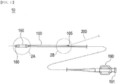
- a balloon catheter 10 is a medical device that widens and treats a lesion area such as a stenosed site formed in a body lumen by inflating a balloon 160, which is disposed on a distal side of a shaft 100, in the lesion area.
- the flat portion 147a by adjusting a cut angle (cut direction) of the inner shaft 140 and cutting away the proximal end of the peripheral edge portion 105a of the proximal opening portion 105 when forming the proximal opening portion 105 and the inclined portion 146 of the inner shaft 140 (refer to Fig. 7 ) .
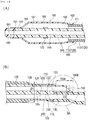
- an axial length L2 of the second region 150B of the inclined portion 146 is shorter than an axial length L3 of the first region 150A of the inclined portion 146.
- the outer distal shaft 120 has a large diameter portion 126 formed having a predetermined outer diameter D1.
- an outer diameter (maximum outer diameter formed by the outer shaft 110 and the inner shaft 140 at a portion corresponding to the first region 150A and the second region 150B) D2 formed by the outer shaft 110 and the inner shaft 140 at a portion corresponding to the first region 150A and the second region 150B is smaller than the outer diameter D1 of the large diameter portion 126.
- the worker may use a well-known mandrel that extends substantially straight in an axial direction.
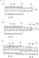
- the worker inserts the first mandrel 310 into the lumen 145 of the inner shaft 140.
- the first mandrel 310 is disposed such that a proximal side of the first mandrel 310 protrudes from the opening portion 143a of the inner shaft 140.
- the worker disposes the outer proximal shaft 130 such that the distal side of the inner shaft 140 is disposed in the lumen 125 of the outer distal shaft 120 and the proximal side of the inner shaft 140 is disposed on the outer surface of the outer proximal shaft 130.
- the worker inserts the second mandrel 320 into the lumen 125 of the outer distal shaft 120 and the lumen 135 of the outer proximal shaft 130.
- the worker disposes the heat shrinkable tube 400 so as to cover the proximal end 123 of the outer distal shaft 120, a distal end 131 of the outer proximal shaft 130, and the inner shaft 140.
- the worker disposes the proximal end 403 of the heat shrinkable tube 400 closer to the distal side in the axial direction than the proximal end 143 of the inner shaft 140, and disposes a distal end 401 of the heat shrinkable tube 400 closer to the distal side in the axial direction than the proximal end 123 of the outer distal shaft 120 and the distal end 131 of the outer proximal shaft 130.
- the worker may use a hollow cylindrical member formed of polyolefin or the like.
- the first region 150A positioned closer to the proximal side than the proximal end 403 of the heat shrinkable tube 400 is affected by heat applied to the heat shrinkable tube 400 when the shafts 120, 130, and 140 are being welded together, the first region 150A has a cross-sectional shape, the thickness of which increases gradually from the distal side toward the proximal side.
- the thickness is maintained substantially constant before and after welding.
- the small diameter portion 127 is formed in a portion of the outer distal shaft 120 which is covered with the heat shrinkable tube 400
- the boundary portion 128 is formed in a portion (positioned closer to the distal side than the small diameter portion 127) thereof which is not covered with the heat shrinkable tube 400
- the large diameter portion 126 is formed on a distal side of the boundary portion 128.
- the worker cuts the inner shaft 140 as described above, the inclined portion 146 inclined from the first region 150A of the inner shaft 140 toward the second region 150B of the inner shaft 140 is formed (refer to Fig. 3 ). At that time, the worker cuts the inner shaft 140 such that the axial length L2 of the second region 150B of the inclined portion 146 is shorter than the axial length L3 of the first region 150A of the inclined portion 146 (refer to Fig. 3 ).
- the proximal opening portion 105 is formed in the inner shaft 140 (refer to Fig. 3 ).
- the worker forms the non-fixed portion 147, which is not fixed to the outer proximal shaft 130, in the peripheral edge portion 105a of the proximal opening portion 105 of the inner shaft 140 (refer to Fig. 4 ).
- the flat portion 147a is formed in the non-fixed portion 147 positioned in the second region 150B
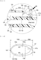
- the opposite portion 148 is formed in the peripheral edge portion 105a of the proximal opening portion 105 at a position opposite to the non-fixed portion 147 in a state where the lumen 145 is interposed between the opposite portion 148 and the non-fixed portion 147, and the side wall portions 149a and 149b are formed connecting the opposite portion 148 to the non-fixed portion 147.
- the balloon catheter 10 includes the inner shaft 140; the outer shaft 110 covering part of the inner shaft 140; and the balloon 160 fixed to the inner shaft 140 and the outer shaft 110.
- the outer shaft 110 has the outer distal shaft 120 having the lumen 125, and the outer proximal shaft 130 fixed to the proximal side of the outer distal shaft 120 and having the lumen 135 communicating with the lumen 125 of the outer distal shaft 120.
- the distal side of the inner shaft 140 is disposed in the lumen 125 of the outer distal shaft 120, and the proximal side of the inner shaft 140 is disposed on the outer surface of the outer proximal shaft 130.
- the inner shaft 140 forms the proximal opening portion 105 which opens on the outer surface side of the outer proximal shaft 130.
- the inner shaft 140 has the first region 150A and the second region 150B disposed on the proximal side of the first region 150A, in the range from the proximal end 123 of the outer distal shaft 120 disposed on the outer surface of the outer proximal shaft 130 to the proximal opening portion 105 of the inner shaft 140.
- the first region 150A is fixed to the outer surface of the outer proximal shaft 130, and the second region 150B is not fixed to the outer surface of the outer proximal shaft 130.
- the foregoing configuration of the balloon catheter 10 can prevent stress from being concentrated in the vicinity of the proximal opening portion 105. In the balloon catheter 10, therefore, the inner shaft 140 can be prevented from being fractured, and a deterioration in the operability of the guide wire 200 can be prevented, which would otherwise be induced by fracturing of the inner shaft 140.
- the second region 150B positioned on the proximal side of the inner shaft 140 is not fixed to the outer surface of the outer proximal shaft 130, when the balloon catheter 10 is delivered to a body lumen such as a curved blood vessel, the balloon catheter 10 is easily deformed such that the second region 150B follows the guide wire 200. Therefore, in the balloon catheter 10, the followability of the inner shaft 140 with respect to the guide wire 200 improves.
- the inner shaft 140 of the balloon catheter 10 has the inclined portion 146 inclined from the first region 150A toward the second region 150B.
- the proximal opening portion 105 is formed in the inclined portion 146.
- the proximal opening portion 105 can be formed having a larger opening area compared to when the proximal opening portion 105 of the inner shaft 140 opens perpendicular to the axial direction of the inner shaft 140. Therefore, an operator can easily take out the guide wire 200 through the proximal opening portion 105 of the balloon catheter 10.
- the proximal opening portion 105 of the balloon catheter 10 has the non-fixed portion 147 at the position of the second region 150B facing the outer surface of the outer proximal shaft 130.
- the non-fixed portion 147 forms the flat portion 147a in the peripheral edge portion 105a of the proximal opening portion 105.
- the flat portion 147a improves the kink resistance of the non-fixed portion 147. Therefore, even though the non-fixed portion 147 is excessively bent when aligned with the guide wire 200 inserted into the lumen 145 of the inner shaft 140, bending of the non-fixed portion 147 can be limited in the balloon catheter 10.
- the balloon catheter 10 can prevent a coil portion or the like of the guide wire 200 from being caught at the proximal end of the proximal opening portion 105. Therefore, the operator can easily and smoothly take the guide wire 200 out from the proximal opening portion 105 of the inner shaft 140.
- the thickness of the flat portion 147a of the inner shaft 140 of the balloon catheter 10 decreases from the distal side toward the proximal side.
- the inner shaft 140 is fixed to the outer shaft 110 at a position closer to the distal side than the portion of the inner shaft 140 in which the flat portion 147a is formed.
- a proximal end (portion having the smallest thickness in the peripheral edge portion 105a of the proximal opening portion 105) of the flat portion 147a formed in the peripheral edge portion 105a of the proximal opening portion 105 of the inner shaft 140 is not fixed to the outer shaft 110.
- the proximal opening portion 105 of the inner shaft 140 of the balloon catheter 10 includes the opposite portion 148 that is opposite to the non-fixed portion 147 in a state where the lumen 145 of the inner shaft 140 is interposed therebetween, and the side wall portions 149a and 149b formed at the positions intersecting the direction along which the non-fixed portion 147 is connected to the opposite portion 148.
- the thickness of each of the side wall portions 149a and 149b increases from the opposite portion 148 toward the flat portion 147a.
- the balloon catheter 10 can prevent the inner shaft 140 from being fractured in the vicinity of the peripheral edge portion 105a of the proximal opening portion 105.
- the proximal opening portion 105 is formed by the inclined portion 146, a cross section of the proximal portion of the inner shaft 140 which is perpendicular to the axial direction of the inner shaft 140 has an area decreasing from the distal side toward the proximal side.
- the balloon catheter 10 it is possible to increase the opening area of the proximal opening portion 105 and to reinforce the peripheral edge portion 105a of the proximal opening portion 105 of the inner shaft 140 by increasing the thickness of the portion of each of the side wall portions 149a and 149b, which is closer to the distal side than the non-fixed portion 147 of the inner shaft 140.
- the balloon catheter 10 in a large range of the inclined portion 146, the inner shaft 140 is in contact with the outer shaft 110 in the axial direction. For this reason, the balloon catheter 10 can have an increased fixing force between the inner shaft 140 and the outer shaft 110 in the inclined portion 146, and reduce the concentration of stress on the peripheral edge portion 105a of the proximal opening portion 105 of the inner shaft 140 by virtue of the non-fixed portion 147. For example, when the guide wire 200 comes into contact with the opposite portion 148 of the inner shaft 140, the balloon catheter 10 can reduce the concentration of stress between the proximal portion of the inner shaft 140 and the outer proximal shaft 130 by virtue of the non-fixed portion 147.
- the balloon catheter 10 can more advantageously prevent the inner shaft 140 or the outer proximal shaft 130 from being fractured in the vicinity of the proximal opening portion 105.
- the outer distal shaft 120 of the balloon catheter 10 has the large diameter portion 126 formed having the predetermined outer diameter, and the outer diameter formed by the outer shaft 110 and the inner shaft 140 at the portion corresponding to the first region 150A and the second region 150B is smaller than the outer diameter of the large diameter portion 126.
- the operator or the like may insert another medical device (for example, a balloon catheter separate from the balloon catheter or a catheter device used in image diagnosis) together with the balloon catheter 10 using one catheter (well-known guiding catheter or the like).
- another medical device for example, a balloon catheter separate from the balloon catheter or a catheter device used in image diagnosis
- one catheter well-known guiding catheter or the like
- the outer diameter formed by the outer shaft 110 and the inner shaft 140 at the portion corresponding to the first region 150A and the second region 150B is smaller than the outer diameter of the large diameter portion 126 of the outer distal shaft 120, it is possible to suitably prevent the balloon catheter 10 from interfering with the other medical device in a lumen of the catheter.
- the method for manufacturing the shaft 100 supplies the outer distal shaft 120, the outer proximal shaft 130, the inner shaft 140, the first mandrel 310 to be disposed in the lumen 145 of the inner shaft 140, and the second mandrel 320 to be disposed in the lumen 125 of the outer distal shaft 120 and the lumen 135 of the outer proximal shaft 130.
- the inner shaft 140 is disposed in the lumen 125 of the outer distal shaft 120, the first mandrel 310 is inserted into the lumen 145 of the inner shaft 140, the outer proximal shaft 130 is disposed such that the distal side of the inner shaft 140 is disposed in the lumen 125 of the outer distal shaft 120 and the proximal side of the inner shaft 140 is disposed on the outer surface of the outer proximal shaft 130, the second mandrel 320 is inserted into the lumen 125 of the outer distal shaft 120 and the lumen 135 of the outer proximal shaft 130, the heat shrinkable tube 400 is disposed so as to cover the proximal end 123 of the outer distal shaft 120, the distal end 131 of the outer proximal shaft, and the inner shaft 140, and the proximal end 403 of the heat shrinkable tube 400 is positioned closer to the distal side than the proximal end 143 of the inner shaft 140.
- the manufacturing method contains welding together the outer distal shaft 120, the outer proximal shaft 130, and the inner shaft 140 in a state where the heat shrinkable tube 400 is shrunk by applying heat thereto and the proximal end 143 of the inner shaft 140 is not welded by the heat shrinkable tube 400.
- the shaft 100 manufactured by the manufacturing method can prevent stress from being concentrated in the vicinity of the proximal end 143 of the inner shaft 140.
- the shaft 100 manufactured by the manufacturing method can prevent stress from being concentrated in the vicinity of the proximal end 143 of the inner shaft 140.
- the vicinity of the proximal end 143 of the inner shaft 140 is easily deformed to follow the guide wire 200. In the shaft 100 manufactured by the manufacturing method, therefore, the inner shaft 140 can have an improved ability to follow the guide wire 200.
- the inner shaft 140 has the first region 150A in which the inner shaft 140 is welded to the outer proximal shaft 130, and the second region 150B which is disposed on the proximal side of the first region 150A and in which the inner shaft 140 is not welded to the outer proximal shaft 130, in a range from the proximal end 123 of the outer distal shaft 120 disposed in an outer surface of the outer shaft 110 to the proximal end 143 of the inner shaft 140.
- the manufacturing method contains obliquely cutting the proximal portion of the inner shaft 140 across the first region 150A and the second region 150B to form the inclined portion 146 inclined from the first region 150A toward the second region 150B.
- the proximal end 143 of the inner shaft 140 is obliquely cut across the first region 150A and the second region 150B to form the inclined portion 146 inclined from the first region 150A toward the second region 150B.
- the proximal opening portion 105 of the inner shaft 140 is formed across the first region 150A of the inner shaft 140 and the second region 150B of the inner shaft 140.
- the opening area of the proximal opening portion 105 is larger compared to when the proximal opening portion 105 of the inner shaft 140 opens perpendicular to the axial direction of the inner shaft 140, and thus the operator can easily take out the guide wire 200 through the proximal opening portion 105 of the balloon catheter 10.
- the shaft 100 can prevent stress from being concentrated at the proximal end of the proximal opening portion 105 of the inner shaft 140. Therefore, the shaft 100 can advantageously prevent the fracturing of the vicinity of the proximal opening portion 105 of the inner shaft 140, which would otherwise be induced by the concentration of stress.
- the method for manufacturing the shaft 100 contains pulling the first mandrel 310 out from the lumen 145 of the inner shaft 140 before cutting the proximal portion of the inner shaft 140. For this reason, in the manufacturing method, when cutting the inner shaft 140, it is possible to prevent the first mandrel 310 from interrupting the smooth progress of the cutting operation. Therefore, a worker manufacturing the shaft 100 can easily cut the proximal portion of the inner shaft 140 into a predetermined shape across the first region 150A and the second region 150B.
- the inner shaft 140 is cut such that in the axial cross-section of the inner shaft 140, the axial length of the second region 150B of the inclined portion 146 is shorter than the axial length of the first region 150A of the inclined portion 146.
- the balloon catheter 10 can have an increased fixing force between the inner shaft 140 and the outer shaft 110 in the inclined portion 146, and reduce the concentration of stress on the peripheral edge portion 105a of the proximal opening portion 105 of the inner shaft 140 by virtue of the non-fixed portion 147.
- the balloon catheter 10 can reduce the concentration of stress between the proximal portion of the inner shaft 140 and the outer proximal shaft 130 by virtue of the non-fixed portion 147.
Landscapes
- Health & Medical Sciences (AREA)
- Life Sciences & Earth Sciences (AREA)
- Heart & Thoracic Surgery (AREA)
- Engineering & Computer Science (AREA)
- Biophysics (AREA)
- Pulmonology (AREA)
- Anesthesiology (AREA)
- Biomedical Technology (AREA)
- Hematology (AREA)
- Animal Behavior & Ethology (AREA)
- General Health & Medical Sciences (AREA)
- Public Health (AREA)
- Veterinary Medicine (AREA)
- Child & Adolescent Psychology (AREA)
- Media Introduction/Drainage Providing Device (AREA)
Applications Claiming Priority (2)
| Application Number | Priority Date | Filing Date | Title |
|---|---|---|---|
| JP2017072815 | 2017-03-31 | ||
| PCT/JP2018/012437 WO2018181315A1 (ja) | 2017-03-31 | 2018-03-27 | バルーンカテーテル、および医療用長尺体の製造方法 |
Publications (4)
| Publication Number | Publication Date |
|---|---|
| EP3603722A1 true EP3603722A1 (de) | 2020-02-05 |
| EP3603722A4 EP3603722A4 (de) | 2021-01-20 |
| EP3603722C0 EP3603722C0 (de) | 2024-10-09 |
| EP3603722B1 EP3603722B1 (de) | 2024-10-09 |
Family
ID=63677193
Family Applications (1)
| Application Number | Title | Priority Date | Filing Date |
|---|---|---|---|
| EP18777292.6A Active EP3603722B1 (de) | 2017-03-31 | 2018-03-27 | Ballonkatheter und verfahren zur herstellung eines medizinischen länglichen körpers |
Country Status (6)
| Country | Link |
|---|---|
| US (1) | US11617869B2 (de) |
| EP (1) | EP3603722B1 (de) |
| JP (1) | JP6931697B2 (de) |
| CN (1) | CN110461403B (de) |
| ES (1) | ES2992069T3 (de) |
| WO (1) | WO2018181315A1 (de) |
Families Citing this family (2)
| Publication number | Priority date | Publication date | Assignee | Title |
|---|---|---|---|---|
| JP7608748B2 (ja) * | 2020-08-18 | 2025-01-07 | ニプロ株式会社 | アブレーションカテーテル及びアブレーションカテーテルの製造方法 |
| WO2022138813A1 (ja) * | 2020-12-25 | 2022-06-30 | テルモ株式会社 | 医療器具、および医療器具の製造方法 |
Family Cites Families (12)
| Publication number | Priority date | Publication date | Assignee | Title |
|---|---|---|---|---|
| US5154725A (en) * | 1991-06-07 | 1992-10-13 | Advanced Cardiovascular Systems, Inc. | Easily exchangeable catheter system |
| US7309350B2 (en) | 2001-12-03 | 2007-12-18 | Xtent, Inc. | Apparatus and methods for deployment of vascular prostheses |
| US7367967B2 (en) * | 2003-09-17 | 2008-05-06 | Boston Scientific Scimed, Inc. | Catheter with sheathed hypotube |
| JP2005211308A (ja) * | 2004-01-29 | 2005-08-11 | Terumo Corp | カテーテルおよびその製造方法 |
| US20070142821A1 (en) * | 2005-12-16 | 2007-06-21 | Medtronic Vascular, Inc. | Rapid exchange catheter having a uniform diameter exchange joint |
| US8382738B2 (en) * | 2006-06-30 | 2013-02-26 | Abbott Cardiovascular Systems, Inc. | Balloon catheter tapered shaft having high strength and flexibility and method of making same |
| AU2009240419A1 (en) * | 2008-04-25 | 2009-10-29 | Nellix, Inc. | Stent graft delivery system |
| JP5952562B2 (ja) * | 2012-01-05 | 2016-07-13 | 株式会社グッドマン | カテーテル及びカテーテルの製造方法 |
| JP6205550B2 (ja) * | 2013-02-07 | 2017-10-04 | テルモ・クリニカルサプライ株式会社 | バルーンカテーテル |
| JP5631475B1 (ja) | 2013-11-14 | 2014-11-26 | 日本ライフライン株式会社 | バルーンカテーテル |
| JP6404619B2 (ja) * | 2014-06-27 | 2018-10-10 | オリンパス株式会社 | カテーテル製造用金型およびカテーテルの製造方法 |
| JP2017072815A (ja) | 2015-10-08 | 2017-04-13 | 三菱瓦斯化学株式会社 | 液晶表示装置の前面板 |
-
2018
- 2018-03-27 EP EP18777292.6A patent/EP3603722B1/de active Active
- 2018-03-27 CN CN201880021472.1A patent/CN110461403B/zh active Active
- 2018-03-27 WO PCT/JP2018/012437 patent/WO2018181315A1/ja not_active Ceased
- 2018-03-27 ES ES18777292T patent/ES2992069T3/es active Active
- 2018-03-27 JP JP2019509888A patent/JP6931697B2/ja active Active
-
2019
- 2019-09-27 US US16/585,037 patent/US11617869B2/en active Active
Also Published As
| Publication number | Publication date |
|---|---|
| CN110461403B (zh) | 2022-07-29 |
| JPWO2018181315A1 (ja) | 2020-02-06 |
| EP3603722C0 (de) | 2024-10-09 |
| WO2018181315A1 (ja) | 2018-10-04 |
| US20200023171A1 (en) | 2020-01-23 |
| ES2992069T3 (es) | 2024-12-09 |
| US11617869B2 (en) | 2023-04-04 |
| CN110461403A (zh) | 2019-11-15 |
| EP3603722B1 (de) | 2024-10-09 |
| EP3603722A4 (de) | 2021-01-20 |
| JP6931697B2 (ja) | 2021-09-08 |
Similar Documents
| Publication | Publication Date | Title |
|---|---|---|
| US10589064B2 (en) | Balloon catheter | |
| US10933220B2 (en) | Balloon catheter | |
| US5514108A (en) | Soft flexible catheter tip for use in angiography | |
| US9199058B2 (en) | Multifilar cable catheter | |
| US10850075B2 (en) | Balloon catheter and manufacturing method of elongated member for balloon catheter | |
| JP4901087B2 (ja) | ステント導入部材、ステントデリバリーカテーテル、及び内視鏡処置システム | |
| JP2004024625A (ja) | カテーテルおよび医療用チューブ | |
| JP7469880B2 (ja) | 生体内留置チューブ | |
| EP3138602B1 (de) | Katheter | |
| JP6876438B2 (ja) | ガイドワイヤー(guide wire)のための挿入補助具(insertion aid)を有するバルーン カテーテル | |
| EP3603722B1 (de) | Ballonkatheter und verfahren zur herstellung eines medizinischen länglichen körpers | |
| JP2001079093A (ja) | バルーンカテーテル用保護具 | |
| JP2020039376A (ja) | バルーンカテーテル | |
| JP7410990B2 (ja) | 生体内留置チューブ | |
| WO2022239763A1 (ja) | カテーテル | |
| US20200155813A1 (en) | Catheter assembly | |
| JP6982061B2 (ja) | バルーンカテーテル、および医療用長尺体の製造方法 | |
| KR101184058B1 (ko) | 벌룬 카테터 | |
| EP4183438A1 (de) | Katheter | |
| WO2024202776A1 (ja) | バルーンカテーテル | |
| JP2013252287A (ja) | バルーンカテーテル |
Legal Events
| Date | Code | Title | Description |
|---|---|---|---|
| STAA | Information on the status of an ep patent application or granted ep patent |
Free format text: STATUS: THE INTERNATIONAL PUBLICATION HAS BEEN MADE |
|
| PUAI | Public reference made under article 153(3) epc to a published international application that has entered the european phase |
Free format text: ORIGINAL CODE: 0009012 |
|
| STAA | Information on the status of an ep patent application or granted ep patent |
Free format text: STATUS: REQUEST FOR EXAMINATION WAS MADE |
|
| 17P | Request for examination filed |
Effective date: 20190821 |
|
| AK | Designated contracting states |
Kind code of ref document: A1 Designated state(s): AL AT BE BG CH CY CZ DE DK EE ES FI FR GB GR HR HU IE IS IT LI LT LU LV MC MK MT NL NO PL PT RO RS SE SI SK SM TR |
|
| AX | Request for extension of the european patent |
Extension state: BA ME |
|
| DAV | Request for validation of the european patent (deleted) | ||
| DAX | Request for extension of the european patent (deleted) | ||
| A4 | Supplementary search report drawn up and despatched |
Effective date: 20201221 |
|
| RIC1 | Information provided on ipc code assigned before grant |
Ipc: A61M 25/10 20130101ALI20201215BHEP Ipc: A61M 25/01 20060101AFI20201215BHEP |
|
| GRAP | Despatch of communication of intention to grant a patent |
Free format text: ORIGINAL CODE: EPIDOSNIGR1 |
|
| STAA | Information on the status of an ep patent application or granted ep patent |
Free format text: STATUS: GRANT OF PATENT IS INTENDED |
|
| INTG | Intention to grant announced |
Effective date: 20240503 |
|
| GRAS | Grant fee paid |
Free format text: ORIGINAL CODE: EPIDOSNIGR3 |
|
| GRAA | (expected) grant |
Free format text: ORIGINAL CODE: 0009210 |
|
| STAA | Information on the status of an ep patent application or granted ep patent |
Free format text: STATUS: THE PATENT HAS BEEN GRANTED |
|
| AK | Designated contracting states |
Kind code of ref document: B1 Designated state(s): AL AT BE BG CH CY CZ DE DK EE ES FI FR GB GR HR HU IE IS IT LI LT LU LV MC MK MT NL NO PL PT RO RS SE SI SK SM TR |
|
| REG | Reference to a national code |
Ref country code: CH Ref legal event code: EP |
|
| REG | Reference to a national code |
Ref country code: DE Ref legal event code: R096 Ref document number: 602018075228 Country of ref document: DE |
|
| REG | Reference to a national code |
Ref country code: IE Ref legal event code: FG4D |
|
| U01 | Request for unitary effect filed |
Effective date: 20241022 |
|
| U07 | Unitary effect registered |
Designated state(s): AT BE BG DE DK EE FI FR IT LT LU LV MT NL PT RO SE SI Effective date: 20241105 |
|
| REG | Reference to a national code |
Ref country code: ES Ref legal event code: FG2A Ref document number: 2992069 Country of ref document: ES Kind code of ref document: T3 Effective date: 20241209 |
|
| U20 | Renewal fee for the european patent with unitary effect paid |
Year of fee payment: 8 Effective date: 20250205 |
|
| PG25 | Lapsed in a contracting state [announced via postgrant information from national office to epo] |
Ref country code: HR Free format text: LAPSE BECAUSE OF FAILURE TO SUBMIT A TRANSLATION OF THE DESCRIPTION OR TO PAY THE FEE WITHIN THE PRESCRIBED TIME-LIMIT Effective date: 20241009 Ref country code: IS Free format text: LAPSE BECAUSE OF FAILURE TO SUBMIT A TRANSLATION OF THE DESCRIPTION OR TO PAY THE FEE WITHIN THE PRESCRIBED TIME-LIMIT Effective date: 20250209 |
|
| PG25 | Lapsed in a contracting state [announced via postgrant information from national office to epo] |
Ref country code: NO Free format text: LAPSE BECAUSE OF FAILURE TO SUBMIT A TRANSLATION OF THE DESCRIPTION OR TO PAY THE FEE WITHIN THE PRESCRIBED TIME-LIMIT Effective date: 20250109 |
|
| PG25 | Lapsed in a contracting state [announced via postgrant information from national office to epo] |
Ref country code: GR Free format text: LAPSE BECAUSE OF FAILURE TO SUBMIT A TRANSLATION OF THE DESCRIPTION OR TO PAY THE FEE WITHIN THE PRESCRIBED TIME-LIMIT Effective date: 20250110 |
|
| PG25 | Lapsed in a contracting state [announced via postgrant information from national office to epo] |
Ref country code: PL Free format text: LAPSE BECAUSE OF FAILURE TO SUBMIT A TRANSLATION OF THE DESCRIPTION OR TO PAY THE FEE WITHIN THE PRESCRIBED TIME-LIMIT Effective date: 20241009 |
|
| PG25 | Lapsed in a contracting state [announced via postgrant information from national office to epo] |
Ref country code: RS Free format text: LAPSE BECAUSE OF FAILURE TO SUBMIT A TRANSLATION OF THE DESCRIPTION OR TO PAY THE FEE WITHIN THE PRESCRIBED TIME-LIMIT Effective date: 20250109 |
|
| PG25 | Lapsed in a contracting state [announced via postgrant information from national office to epo] |
Ref country code: SM Free format text: LAPSE BECAUSE OF FAILURE TO SUBMIT A TRANSLATION OF THE DESCRIPTION OR TO PAY THE FEE WITHIN THE PRESCRIBED TIME-LIMIT Effective date: 20241009 |
|
| PGFP | Annual fee paid to national office [announced via postgrant information from national office to epo] |
Ref country code: ES Payment date: 20250403 Year of fee payment: 8 |
|
| PG25 | Lapsed in a contracting state [announced via postgrant information from national office to epo] |
Ref country code: SK Free format text: LAPSE BECAUSE OF FAILURE TO SUBMIT A TRANSLATION OF THE DESCRIPTION OR TO PAY THE FEE WITHIN THE PRESCRIBED TIME-LIMIT Effective date: 20241009 |
|
| PG25 | Lapsed in a contracting state [announced via postgrant information from national office to epo] |
Ref country code: CZ Free format text: LAPSE BECAUSE OF FAILURE TO SUBMIT A TRANSLATION OF THE DESCRIPTION OR TO PAY THE FEE WITHIN THE PRESCRIBED TIME-LIMIT Effective date: 20241009 |
|
| PLBE | No opposition filed within time limit |
Free format text: ORIGINAL CODE: 0009261 |
|
| STAA | Information on the status of an ep patent application or granted ep patent |
Free format text: STATUS: NO OPPOSITION FILED WITHIN TIME LIMIT |
|
| 26N | No opposition filed |
Effective date: 20250710 |
|
| PG25 | Lapsed in a contracting state [announced via postgrant information from national office to epo] |
Ref country code: MC Free format text: LAPSE BECAUSE OF FAILURE TO SUBMIT A TRANSLATION OF THE DESCRIPTION OR TO PAY THE FEE WITHIN THE PRESCRIBED TIME-LIMIT Effective date: 20241009 |
|
| REG | Reference to a national code |
Ref country code: CH Ref legal event code: H13 Free format text: ST27 STATUS EVENT CODE: U-0-0-H10-H13 (AS PROVIDED BY THE NATIONAL OFFICE) Effective date: 20251023 |
|
| PG25 | Lapsed in a contracting state [announced via postgrant information from national office to epo] |
Ref country code: CH Free format text: LAPSE BECAUSE OF NON-PAYMENT OF DUE FEES Effective date: 20250331 |
|
| PG25 | Lapsed in a contracting state [announced via postgrant information from national office to epo] |
Ref country code: IE Free format text: LAPSE BECAUSE OF NON-PAYMENT OF DUE FEES Effective date: 20250327 |
|
| U20 | Renewal fee for the european patent with unitary effect paid |
Year of fee payment: 9 Effective date: 20260209 |
|
| PGFP | Annual fee paid to national office [announced via postgrant information from national office to epo] |
Ref country code: GB Payment date: 20260209 Year of fee payment: 9 |