EP3603722B1 - Ballonkatheter und verfahren zur herstellung eines medizinischen länglichen körpers - Google Patents
Ballonkatheter und verfahren zur herstellung eines medizinischen länglichen körpers Download PDFInfo
- Publication number
- EP3603722B1 EP3603722B1 EP18777292.6A EP18777292A EP3603722B1 EP 3603722 B1 EP3603722 B1 EP 3603722B1 EP 18777292 A EP18777292 A EP 18777292A EP 3603722 B1 EP3603722 B1 EP 3603722B1
- Authority
- EP
- European Patent Office
- Prior art keywords
- shaft
- proximal
- inner shaft
- region
- distal
- Prior art date
- Legal status (The legal status is an assumption and is not a legal conclusion. Google has not performed a legal analysis and makes no representation as to the accuracy of the status listed.)
- Active
Links
Images


Classifications
-
- A—HUMAN NECESSITIES
- A61—MEDICAL OR VETERINARY SCIENCE; HYGIENE
- A61M—DEVICES FOR INTRODUCING MEDIA INTO, OR ONTO, THE BODY; DEVICES FOR TRANSDUCING BODY MEDIA OR FOR TAKING MEDIA FROM THE BODY; DEVICES FOR PRODUCING OR ENDING SLEEP OR STUPOR
- A61M25/00—Catheters; Hollow probes
- A61M25/10—Balloon catheters
- A61M25/1025—Connections between catheter tubes and inflation tubes
-
- A—HUMAN NECESSITIES
- A61—MEDICAL OR VETERINARY SCIENCE; HYGIENE
- A61M—DEVICES FOR INTRODUCING MEDIA INTO, OR ONTO, THE BODY; DEVICES FOR TRANSDUCING BODY MEDIA OR FOR TAKING MEDIA FROM THE BODY; DEVICES FOR PRODUCING OR ENDING SLEEP OR STUPOR
- A61M25/00—Catheters; Hollow probes
- A61M25/0043—Catheters; Hollow probes characterised by structural features
- A61M25/005—Catheters; Hollow probes characterised by structural features with embedded materials for reinforcement, e.g. wires, coils, braids
- A61M25/0052—Localized reinforcement, e.g. where only a specific part of the catheter is reinforced, for rapid exchange guidewire port
-
- A—HUMAN NECESSITIES
- A61—MEDICAL OR VETERINARY SCIENCE; HYGIENE
- A61M—DEVICES FOR INTRODUCING MEDIA INTO, OR ONTO, THE BODY; DEVICES FOR TRANSDUCING BODY MEDIA OR FOR TAKING MEDIA FROM THE BODY; DEVICES FOR PRODUCING OR ENDING SLEEP OR STUPOR
- A61M25/00—Catheters; Hollow probes
- A61M25/01—Introducing, guiding, advancing, emplacing or holding catheters
-
- A—HUMAN NECESSITIES
- A61—MEDICAL OR VETERINARY SCIENCE; HYGIENE
- A61M—DEVICES FOR INTRODUCING MEDIA INTO, OR ONTO, THE BODY; DEVICES FOR TRANSDUCING BODY MEDIA OR FOR TAKING MEDIA FROM THE BODY; DEVICES FOR PRODUCING OR ENDING SLEEP OR STUPOR
- A61M25/00—Catheters; Hollow probes
- A61M25/10—Balloon catheters
- A61M25/1006—Balloons formed between concentric tubes
-
- A—HUMAN NECESSITIES
- A61—MEDICAL OR VETERINARY SCIENCE; HYGIENE
- A61M—DEVICES FOR INTRODUCING MEDIA INTO, OR ONTO, THE BODY; DEVICES FOR TRANSDUCING BODY MEDIA OR FOR TAKING MEDIA FROM THE BODY; DEVICES FOR PRODUCING OR ENDING SLEEP OR STUPOR
- A61M25/00—Catheters; Hollow probes
- A61M25/10—Balloon catheters
- A61M25/1027—Making of balloon catheters
- A61M25/1034—Joining of shaft and balloon
-
- A—HUMAN NECESSITIES
- A61—MEDICAL OR VETERINARY SCIENCE; HYGIENE
- A61M—DEVICES FOR INTRODUCING MEDIA INTO, OR ONTO, THE BODY; DEVICES FOR TRANSDUCING BODY MEDIA OR FOR TAKING MEDIA FROM THE BODY; DEVICES FOR PRODUCING OR ENDING SLEEP OR STUPOR
- A61M25/00—Catheters; Hollow probes
- A61M25/10—Balloon catheters
- A61M25/1027—Making of balloon catheters
- A61M25/1036—Making parts for balloon catheter systems, e.g. shafts or distal ends
-
- A—HUMAN NECESSITIES
- A61—MEDICAL OR VETERINARY SCIENCE; HYGIENE
- A61M—DEVICES FOR INTRODUCING MEDIA INTO, OR ONTO, THE BODY; DEVICES FOR TRANSDUCING BODY MEDIA OR FOR TAKING MEDIA FROM THE BODY; DEVICES FOR PRODUCING OR ENDING SLEEP OR STUPOR
- A61M25/00—Catheters; Hollow probes
- A61M25/01—Introducing, guiding, advancing, emplacing or holding catheters
- A61M2025/0183—Rapid exchange or monorail catheters
-
- A—HUMAN NECESSITIES
- A61—MEDICAL OR VETERINARY SCIENCE; HYGIENE
- A61M—DEVICES FOR INTRODUCING MEDIA INTO, OR ONTO, THE BODY; DEVICES FOR TRANSDUCING BODY MEDIA OR FOR TAKING MEDIA FROM THE BODY; DEVICES FOR PRODUCING OR ENDING SLEEP OR STUPOR
- A61M25/00—Catheters; Hollow probes
- A61M25/01—Introducing, guiding, advancing, emplacing or holding catheters
- A61M25/09—Guide wires
- A61M2025/09008—Guide wires having a balloon
-
- A—HUMAN NECESSITIES
- A61—MEDICAL OR VETERINARY SCIENCE; HYGIENE
- A61M—DEVICES FOR INTRODUCING MEDIA INTO, OR ONTO, THE BODY; DEVICES FOR TRANSDUCING BODY MEDIA OR FOR TAKING MEDIA FROM THE BODY; DEVICES FOR PRODUCING OR ENDING SLEEP OR STUPOR
- A61M25/00—Catheters; Hollow probes
- A61M25/01—Introducing, guiding, advancing, emplacing or holding catheters
- A61M25/09—Guide wires
- A61M2025/09116—Design of handles or shafts or gripping surfaces thereof for manipulating guide wires
Definitions
- the present invention relates to a balloon catheter and a method for manufacturing a medical elongated body.
- a balloon catheter is widely known as a medical device that dilates a lesion area such as a stenosed site formed in a body lumen such as a blood vessel.
- a lesion area such as a stenosed site formed in a body lumen such as a blood vessel.
- an over-the-wire type balloon catheter and a rapid exchange type balloon catheter.
- a guide wire lumen into which a guide wire is inserted is formed only on a distal side of a catheter shaft in which a balloon is disposed. For this reason, a guide wire port (proximal opening portion) through which the guide wire can be inserted into and removed from the guide wire lumen is provided at a predetermined position on the distal side of the catheter shaft in an axial direction (longitudinal direction) .
- each of the outer distal shaft and the outer proximal shaft is a tubular member forming an inflation lumen through which a pressurizing medium (working fluid) for inflating a balloon flows.
- the inner shaft is a tubular member including a lumen forming a guide wire lumen.
- US2017080181 discloses the preamble of claim 1.
- US2007142821 discloses a method for manufacturing a medical elongated body comprising supplying an outer distal shaft, outer proximal shaft, an inner shaft, a first mandrel to be disposed in a lumen of the inner shaft, and a second mandrel to be disposed in a lumen of the outer distal shaft and a lumen of the outer proximal shaft; the method involving disposing a heat shrinkable tube so as to cover a distal end of the outer proximal shaft and the inner shaft.
- an operator such as a physician inserts the guide wire into a lesion area such as a stenosed site formed in a blood vessel.
- the operator inserts a proximal side of the guide wire into the guide wire lumen from a distal side of the inner shaft, and causes the guide wire to come out from the guide wire lumen through the guide wire port on the proximal side of the inner shaft.
- the operator guides the balloon of the balloon catheter to the lesion area by moving the balloon catheter along the guide wire .
- the operator moves the guide wire to a proximal side or a distal side in a state where the guide wire is inserted into the guide wire lumen of the balloon catheter, and takes the guide wire out from a proximal opening portion of the inner shaft.
- the operator performs such operation, if stress is excessively concentrated in the vicinity of the guide wire port of the inner shaft, there is a potential that the inner shaft of the balloon catheter may be fractured. If the guide wire is caught in a fractured portion (torn-out portion) of the inner shaft, since the operator has difficulties in smoothly moving the guide wire, the operability of the guide wire deteriorates remarkably.
- the present invention has been made in light of the problem, and an object of the present invention is to provide a balloon catheter in which the vicinity of the proximal opening portion formed by the inner shaft can be prevented from being fractured and to provide a method for manufacturing a medical elongated body.
- a balloon catheter including an inner shaft; an outer shaft covering a part of the inner shaft; and a balloon fixed to the inner shaft and the outer shaft.
- the outer shaft has an outer distal shaft having a lumen, and an outer proximal shaft fixed to a proximal side of the outer distal shaft and having a lumen communicating with the lumen of the outer distal shaft.
- a distal side of the inner shaft is disposed in the lumen of the outer distal shaft, a proximal side of the inner shaft is disposed on an outer surface of the outer proximal shaft, and the inner shaft forms a proximal opening portion which opens on an outer surface side of the outer proximal shaft.
- the inner shaft has a first region and a second region disposed on a proximal side of the first region, in a range from a proximal end of the outer distal shaft disposed on the outer surface of the outer proximal shaft to the proximal opening portion.
- the first region is fixed to the outer surface of the outer proximal shaft.
- the second region is not fixed to the outer surface of the outer proximal shaft.
- the outer diameter of the outer proximal shaft is smaller than the outer diameter of the outer distal shaft.
- a method for manufacturing a medical elongated body including supplying an outer distal shaft, an outer proximal shaft, an inner shaft, a first mandrel to be disposed in a lumen of the inner shaft, and a second mandrel to be disposed in a lumen of the outer distal shaft and a lumen of the outer proximal shaft; disposing the inner shaft in the lumen of the outer distal shaft; inserting the first mandrel into the lumen of the inner shaft; disposing the outer proximal shaft such that a distal side of the inner shaft is disposed in the lumen of the outer distal shaft and a proximal side of the inner shaft is disposed on an outer surface of the outer proximal shaft; inserting the second mandrel into the lumen of the outer distal shaft and the lumen of the outer proximal shaft; disposing a heat shrinkable tube so as to cover a proximal end of the outer dis
- the second region positioned on the proximal side of the inner shaft is not fixed to the outer surface of the outer proximal shaft. Therefore, for example, when the guide wire is being taken out from the proximal opening portion of the inner shaft, the foregoing configuration of the balloon catheter can prevent stress from being concentrated in the vicinity of the proximal opening portion. In the balloon catheter, therefore, the inner shaft can be prevented from being fractured, and a deterioration in the operability of the guide wire can be prevented, which would otherwise be induced by fracturing of the inner shaft.
- the balloon catheter improves the followability of the inner shaft with respect to the guide wire.
- the vicinity of the proximal end of the inner shaft is easily deformed to follow the guide wire, so that the inner shaft in the medical elongated body manufactured by the manufacturing method has an improved ability to follow the guide wire.
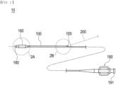
- a balloon catheter 10 is a medical device that widens and treats a lesion area such as a stenosed site formed in a body lumen by inflating a balloon 160, which is disposed on a distal side of a shaft 100, in the lesion area.
- the balloon catheter 10 is configured as a balloon catheter used in the PTCA treatment which is used to widen a stenosed site in a coronary artery.
- the balloon catheter 10 can be also configured as a balloon catheter intended to treat a lesion area such as a stenosed site formed in body organs such as other blood vessels, biliary duct, trachea, esophagus, other digestive tracts, urethra, ear and nose cavity, and other organs.
- the balloon catheter 10 has an elongated shaft (equivalent to a "medical elongated body") 100; the balloon 160 disposed on the distal side of the shaft 100; and a hub 190 disposed on a proximal side of the shaft 100.
- a side on which the balloon 160 is disposed refers to a distal side of the balloon catheter 10
- a side on which the hub 190 is disposed refers to a proximal side of the balloon catheter 10
- a stretching direction of the shaft 100 refers to an axial direction.
- a distal portion indicates a certain range containing a distal end (distalmost end) and the vicinity of the distal end
- a proximal portion indicates a certain range containing a proximal end (proximalmost end) and the vicinity of the proximal end.
- the balloon catheter 10 is configured as a so-called rapid exchange type catheter in which a proximal opening portion (guide wire port) 105, through which a guide wire 200 can be inserted and removed, is formed close to the distal side of the shaft 100.
- a proximal opening portion (guide wire port) 105 through which a guide wire 200 can be inserted and removed, is formed close to the distal side of the shaft 100.
- the shaft 100 has an outer shaft 110 including a lumen (inflation lumen) 115, and an inner shaft 140 including a lumen (guide wire lumen) 145 which is disposed in the lumen 115 of the outer shaft 110 and into which the guide wire 200 is inserted.
- the shaft 100 has the proximal opening portion (equivalent to a "proximal opening portion of the inner shaft") 105 communicating with the lumen 145 of the inner shaft 140.
- the proximal opening portion 105 is formed in the vicinity of a proximal end of the inner shaft 140.
- the outer shaft 110 has an outer distal shaft 120, and an outer proximal shaft 130 fixed to a proximal side of the outer distal shaft 120.
- the outer distal shaft 120 is formed as a tubular member in which a lumen 125 extending in the axial direction is formed.
- the outer proximal shaft 130 is formed as a tubular member in which a lumen 135 extending in the axial direction is formed.
- the outer distal shaft 120 and the outer proximal shaft 130 are integrally connected (welded) to the inner shaft 140 in the vicinity of the proximal opening portion 105 of the shaft 100.
- the lumen 125 of the outer distal shaft 120 communicates with the lumen 135 of the outer proximal shaft 130.
- the lumen 125 and the lumen 135 form the lumen (inflation lumen) 115 communicating with an inflation space 167 of the balloon 160.
- the outer distal shaft 120 and the outer proximal shaft 130 can be formed of, for example, polyolefin such as polyethylene, polypropylene, ethylene-propylene copolymer, or ethylene-vinyl acetate copolymer, thermoplastic resin such as soft polyvinyl chloride, any of various elastomers such as polyurethane elastomer, polyamide elastomer, and polyester elastomer, polyamide, or crystalline plastic such as polyamide, crystalline polyethylene, or crystalline polypropylene.
- polyolefin such as polyethylene, polypropylene, ethylene-propylene copolymer, or ethylene-vinyl acetate copolymer
- thermoplastic resin such as soft polyvinyl chloride
- any of various elastomers such as polyurethane elastomer, polyamide elastomer, and polyester elastomer, polyamide, or crystalline plastic such as polyamide, crystalline polyethylene, or crystalline polyprop
- a distal side of the inner shaft 140 is disposed in the lumen 125 of the outer distal shaft 120.
- a certain range on the distal side of the inner shaft 140 is disposed protruding to a distal side of the outer distal shaft 120.
- the inner shaft 140 is configured such that a proximal side of the inner shaft 140 is disposed on an outer surface of the outer proximal shaft 130.
- the proximal opening portion 105 which opens on an outer surface side of the outer proximal shaft 130 is formed on the proximal side of the inner shaft 140.
- a first region 150A and a second region 150B which will be described later are formed on the proximal side of the inner shaft 140.
- the inner shaft 140 has a distal member 180 disposed on the distal side.
- the distal member 180 has a lumen 181 into which the guide wire 200 can be inserted.
- the inner shaft 140 includes the distal member 180 on the distal side, when a distal end of the balloon catheter 10 comes into contact with a body lumen (intravascular wall or the like), the distal end is prevented from causing damages to a body organ.
- the distal member 180 can be formed of, for example, a flexible resin material. However, the material of the distal member 180 is not specifically limited if the distal member 180 can be fixed to the inner shaft 140.
- the lumen 145 of the inner shaft 140 communicates with the lumen 181 of the distal member 180 on the distal side of the inner shaft 140.
- the lumen 145 of the inner shaft 140 communicates with the proximal opening portion 105 on the proximal side of the inner shaft 140.
- the inner shaft 140 can be formed of, for example, the same materials as the materials exemplified as the configuration material of the outer shaft 110.
- the balloon 160 has a distal portion 161 fixed to a distal portion of the inner shaft 140; a proximal portion 163 fixed to a distal portion of the outer shaft 110 (distal portion of the outer distal shaft 120); and an intermediate portion 166 that forms a maximum outer diameter portion formed between the distal portion 161 of the balloon 160 and the proximal portion 163 of the balloon 160.
- the balloon 160 has a distal side tapered portion 164 formed between the distal portion 161 of the balloon 160 and the intermediate portion 166 of the balloon 160, and a proximal side tapered portion 165 formed between the proximal portion 163 of the balloon 160 and the intermediate portion 166 of the balloon 160.
- the balloon 160 has the inflation space 167 formed between the balloon 160 and an outer circumferential surface of the shaft 100 and communicating with the lumen 115 of the outer shaft 110. If a fluid flows into the inflation space 167, the balloon 160 is inflated in a radial direction of the balloon 160 which intersects the axial direction.
- the balloon 160 can be formed of, for example, polyolefin such as polyethylene, polypropylene, or ethylene-propylene copolymer, polyester such as polyethylene terephthalate, thermoplastic resin such as polyvinyl chloride, ethylene-vinyl acetate copolymer, cross-linked ethylene-vinyl acetate copolymer, or polyurethane, polyamide, polyamide elastomer, polystyrene elastomer, silicone rubber, or latex rubber.
- polyolefin such as polyethylene, polypropylene, or ethylene-propylene copolymer
- polyester such as polyethylene terephthalate
- thermoplastic resin such as polyvinyl chloride, ethylene-vinyl acetate copolymer, cross-linked ethylene-vinyl acetate copolymer, or polyurethane
- polyamide, polyamide elastomer, polystyrene elastomer, silicone rubber, or latex rubber such as poly
- the inner shaft 140 has a contrast marker 170 indicating substantially an axially central position of the intermediate portion 166 of the balloon 160.
- the contrast marker 170 can be formed of, for example, metal such as platinum, gold, silver, iridium, titanium, or tungsten, or alloys thereof. Note that the contrast marker 170 may be disposed at a position indicating a boundary portion between the distal side tapered portion 164 and the intermediate portion 166 in the inner shaft 140, or at a position indicating a boundary portion between the proximal side tapered portion 165 and the intermediate portion 166 in the inner shaft 140.
- the hub 190 has a port 191 that can be liquid-tightly and air-tightly connected to a supply device (not illustrated) such as an indeflator for supplying a fluid (for example, contrast agent or physiological salt solution).
- a supply device such as an indeflator for supplying a fluid (for example, contrast agent or physiological salt solution).
- the port 191 of the hub 190 can be configured as a well-known Lure taper or the like which is configured such that a tube or the like can be connected to and detached therefrom.
- the inner shaft 140 has the first region 150A, and the second region 150B disposed on a proximal side of the first region 150A.
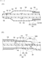
- Fig. 3 is an enlarged cross-sectional view (enlarged cross-sectional view of the inner shaft 140 in the axial direction) of a portion 3A surrounded by the broken line illustrated in Fig. 2(B) .
- the first region 150A is a region where the inner shaft 140 and the outer proximal shaft 130 are fixed (welded) together in a range from a proximal end 123 of the outer distal shaft 120 to the proximal opening portion 105 of the inner shaft 140 (in an axial range from the proximal end 123 of the outer distal shaft 120 to a proximal end of the proximal opening portion 105 of the inner shaft 140).
- the second region 150B is a region where the inner shaft 140 and the outer proximal shaft 130 are not fixed (welded) together in the range from the proximal end 123 of the outer distal shaft 120 to the proximal opening portion 105 of the inner shaft 140.
- the first region 150A is formed in a region where a heat shrinkable tube 400 is disposed in the inner shaft 140 when welding together the shafts 120, 130, and 140.
- the second region 150B is formed in a region located farther to the proximal side than the region where the heat shrinkable tube 400 is disposed in the inner shaft 140 (refer to Figs. 6(B) and 6(C) ).
- the inner shaft 140 has an inclined portion 146 inclined from the first region 150A to the second region 150B.
- the proximal opening portion 105 of the inner shaft 140 is formed in the inclined portion 146.
- the proximal opening portion 105 of the inner shaft 140 is inclined from the proximal side of the inner shaft 140 to the distal side. Since the proximal opening portion 105 is formed in the inclined portion 146, the proximal opening portion 105 and the inclined portion 146 are disposed on the same plane.
- the inclined angle of the inclined portion 146 inclined with respect to the axial direction is not specifically limited.
- the proximal opening portion 105 may not be formed in the inclined portion 146, but instead, for example, may be formed in such a way that the proximal opening portion 105 opens substantially perpendicular to the axial direction of the inner shaft 140.
- proximal opening portion 105 of the inner shaft 140 has a non-fixed portion 147 at the position of the second region 150B facing the outer surface of the outer proximal shaft 130.
- Fig. 4 is an arrow view of the inner shaft 140 taken in the direction of an arrow head 4A illustrated in Fig. 3 .
- the non-fixed portion 147 is formed in a proximal portion of a peripheral edge portion 105a of the proximal opening portion 105. In addition, the non-fixed portion 147 forms a flat portion 147a in the peripheral edge portion 105a of the proximal opening portion 105.
- the flat portion 147a is formed at a proximal end of the peripheral edge portion 105a of the proximal opening portion 105 and in the vicinity of the proximal end such that the flat portion 147a is continuous with an inner surface of the inner shaft 140.
- the flat portion 147a is formed such that a width W1 of the flat portion 147a along the axial direction of the inner shaft 140 is longer than the width of an opposite portion 148 (which will be described later) (region formed at a distal end of the peripheral edge portion 105a of the proximal opening portion 105 and in the vicinity of the distal end), and a distance L1 of the flat portion 147a in a direction perpendicular to the axial direction of the inner shaft 140 is longer than the distance of the opposite portion 148 (which will be described later) (region formed at the distal end of the peripheral edge portion 105a of the proximal opening portion 105 and in the vicinity of the distal end) .
- the flat portion 147a is formed in a region in the peripheral edge portion 105a of the proximal opening portion 105, in which the thickness of the inner shaft 140 is large and the circumferential length of the inner shaft 140 is long, even though the non-fixed portion 147 is excessively bent due to being aligned with the guide wire inserted into the lumen 145 of the inner shaft 140, it is possible to restrain the non-fixed portion 147 from being bent and improve the operability of the guide wire operated by an operator.
- the flat portion 147a by adjusting a cut angle (cut direction) of the inner shaft 140 and cutting away the proximal end of the peripheral edge portion 105a of the proximal opening portion 105 when forming the proximal opening portion 105 and the inclined portion 146 of the inner shaft 140 (refer to Fig. 7 ) .
- the flat portion 147a is formed such that a thickness t1 of the flat portion 147a decreases from the distal side toward the proximal side in the axial direction.
- the thickness t1 of the flat portion 147a decreases gradually toward the proximal side along an inclined direction of the inclined portion 146, and becomes minimum at the proximal end of the peripheral edge portion 105a of the proximal opening portion 105.
- the proximal opening portion 105 includes the opposite portion 148 that is opposite to the non-fixed portion 147 in a state where the lumen 145 (or the proximal opening portion 105) of the inner shaft 140 is interposed therebetween, and a pair of side wall portions 149a and 149b at positions intersecting a direction (rightward and leftward direction in Fig. 4 ) along which the non-fixed portion 147 is connected to the opposite portion 148.
- each of the side wall portions 149a and 149b increases from the opposite portion 148 toward the flat portion 147a.
- a width W2 (refer to Fig. 4 ) of each of the side wall portions 149a and 149b increases from the opposite portion 148 toward the flat portion 147a.
- the opposite portion 148 is formed in a portion covered with the heat shrinkable tube 400 when the shafts 120, 130, and 140 are welded together.
- at least part of each of the side wall portions 149a and 149b is disposed closer to the proximal side than a proximal end 403 of the heat shrinkable tube 400 (refer to Fig. 6(C) ).
- heat applied to the heat shrinkable tube 400 affects a certain range closer to the proximal side than the proximal end 403 of the heat shrinkable tube 400.
- a portion of the inner shaft 140 in which each of the side wall portions 149a and 149b is formed has a thickness after welding and the width W2 which increase from the distal side relatively highly affected by heat applied to the heat shrinkable tube 400 toward the proximal side not much affected by heat. Therefore, as illustrated in Figs. 3 and 4 , the proximal opening portion 105 is formed such that the thickness and the width W2 increase from the opposite portion 148 toward the flat portion 147a.
- an axial length L2 of the second region 150B of the inclined portion 146 is shorter than an axial length L3 of the first region 150A of the inclined portion 146.
- the axial length of the second region 150B of the inclined portion 146 can be set, for example, from 0.1 mm to 0.5 mm, and the axial length of the first region 150A of the inclined portion 146 can be set, for example, from 0.4 mm to 2.5 mm.
- the outer distal shaft 120 has a large diameter portion 126 formed having a predetermined outer diameter D1.
- an outer diameter (maximum outer diameter formed by the outer shaft 110 and the inner shaft 140 at a portion corresponding to the first region 150A and the second region 150B) D2 formed by the outer shaft 110 and the inner shaft 140 at a portion corresponding to the first region 150A and the second region 150B is smaller than the outer diameter D1 of the large diameter portion 126.
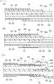
- a predetermined range of the shafts 120, 130, and 140 are covered with the heat shrinkable tube 400. If heat is applied to the shafts 120, 130, and 140 in this state, a range of the shafts 120, 130, and 140 covered with the heat shrinkable tube 400 shrink radially inward (in a direction toward the inside of the shaft 100) . At that time, a range of the outer distal shaft 120 which is not affected by heat maintains a constant outer diameter before and after welding. As illustrated in Fig.
- a portion of the outer distal shaft 120 which maintains the constant outer diameter before and after welding, forms the large diameter portion 126.
- a portion of the outer distal shaft 120 which has an outer diameter decreased after the shafts 120, 130, and 140 are welded together, namely, the portion covered with the heat shrinkable tube 400 when the shafts 120, 130, and 140 are being welded together forms a small diameter portion 127 having an outer diameter smaller than the outer diameter of the large diameter portion 126.
- a boundary portion 128 is formed between the large diameter portion 126 and the small diameter portion 127, and heat applied to the heat shrinkable tube 400 causes the outer diameter of the boundary portion 128 to increase gradually from the small diameter portion 127 toward the large diameter portion 126.
- a worker manufacturing the shaft 100 supplies (prepares) the outer distal shaft 120, the outer proximal shaft 130, the inner shaft 140, a first mandrel 310 to be disposed in the lumen 145 of the inner shaft 140, and a second mandrel 320 to be disposed in the lumen 125 of the outer distal shaft 120 and the lumen 135 of the outer proximal shaft 130.
- the worker prepares a tubular member having an outer diameter and an inner diameter which are substantially constant in an axial direction.
- the worker prepares a tubular member, the distal end of which is obliquely inclined from a distal side toward a proximal side, and in which a portion other than the distal end has an outer diameter and an inner diameter which are substantially constant in an axial direction.
- the inner shaft 140 for example, the worker prepares a tubular member having an outer diameter and an inner diameter which are substantially constant in an axial direction, and in which an opening portion 143a is formed in a proximal end 143 (refer to Fig. 5(C) for an example of the shape of each of the shafts 120, 130, and 140) .
- the worker may use a well-known mandrel that extends substantially straight in an axial direction.
- the worker disposes the inner shaft 140 in the lumen 125 of the outer distal shaft 120. At that time, the worker disposes the inner shaft 140 such that the proximal side of the inner shaft 140 protrudes by a predetermined range from the proximal end 123 of the outer distal shaft 120.
- the worker inserts the first mandrel 310 into the lumen 145 of the inner shaft 140.
- the first mandrel 310 is disposed such that a proximal side of the first mandrel 310 protrudes from the opening portion 143a of the inner shaft 140.
- the worker disposes the outer proximal shaft 130 such that the distal side of the inner shaft 140 is disposed in the lumen 125 of the outer distal shaft 120 and the proximal side of the inner shaft 140 is disposed on the outer surface of the outer proximal shaft 130.
- the worker inserts the second mandrel 320 into the lumen 125 of the outer distal shaft 120 and the lumen 135 of the outer proximal shaft 130.
- the worker may perform, in random order, the operation of disposing the inner shaft 140 in the lumen 125 of the outer distal shaft 120, the operation of disposing the first mandrel 310 in the inner shaft 140, the operation of disposing the outer proximal shaft 130 in the outer distal shaft 120, and the operation of inserting the second mandrel 320 into the lumen 125 of the outer distal shaft 120 and the lumen 135 of the outer proximal shaft 130.
- the worker disposes the heat shrinkable tube 400 so as to cover the proximal end 123 of the outer distal shaft 120, a distal end 131 of the outer proximal shaft 130, and the inner shaft 140.
- the worker disposes the proximal end 403 of the heat shrinkable tube 400 closer to the distal side in the axial direction than the proximal end 143 of the inner shaft 140, and disposes a distal end 401 of the heat shrinkable tube 400 closer to the distal side in the axial direction than the proximal end 123 of the outer distal shaft 120 and the distal end 131 of the outer proximal shaft 130.
- the worker may use a hollow cylindrical member formed of polyolefin or the like.
- the worker causes the heat shrinkable tube 400 to shrink by applying heat thereto, and welds together the outer distal shaft 120, the outer proximal shaft 130, and the inner shaft 140 in a state where the proximal end 143 of the inner shaft 140 is not welded by the heat shrinkable tube 400. If the heat shrinkable tube 400 is heated, the heat shrinkable tube 400 shrinks and is deformed such that the inner diameter of the heat shrinkable tube 400 after being heated becomes smaller than the inner diameter of the heat shrinkable tube 400 before being heated.
- the worker welds together the shafts 120, 130, and 140 by causing the heat shrinkable tube 400 to shrink, so that as illustrated in Fig. 6(C) , the first region 150A and the second region 150B are formed in the inner shaft 140.
- the first region 150A positioned closer to the proximal side than the proximal end 403 of the heat shrinkable tube 400 is affected by heat applied to the heat shrinkable tube 400 when the shafts 120, 130, and 140 are being welded together, the first region 150A has a cross-sectional shape, the thickness of which increases gradually from the distal side toward the proximal side.
- the thickness is maintained substantially constant before and after welding.
- the outer proximal shaft 130 has such cross-sectional shape that the thickness of the portion increases from the distal side toward the proximal side.
- the thickness of a portion of the outer proximal shaft 130 which is spaced apart by a predetermined distance from the proximal end 403 of the heat shrinkable tube 400 toward the proximal side, is maintained substantially constant before and after welding.
- the small diameter portion 127 is formed in a portion of the outer distal shaft 120 which is covered with the heat shrinkable tube 400
- the boundary portion 128 is formed in a portion (positioned closer to the distal side than the small diameter portion 127) thereof which is not covered with the heat shrinkable tube 400
- the large diameter portion 126 is formed on a distal side of the boundary portion 128.
- the worker pulls the first mandrel 310 out from the lumen 145 of the inner shaft 140.
- the worker may pull the second mandrel 320 out from the lumen 125 of the outer distal shaft 120 and the lumen 135 of the outer proximal shaft 130, and pulling the first mandrel 310 out from the lumen 145 of the inner shaft 140.
- the worker pulls out the mandrels 310 and 320 after welding.
- Fig. 7 is an enlarged cross-sectional view of a portion surrounded by a broken line portion 7A of Fig. 6(C) , and a view for describing the cut position.
- the worker cuts the inner shaft 140 as described above, the inclined portion 146 inclined from the first region 150A of the inner shaft 140 toward the second region 150B of the inner shaft 140 is formed (refer to Fig. 3 ). At that time, the worker cuts the inner shaft 140 such that the axial length L2 of the second region 150B of the inclined portion 146 is shorter than the axial length L3 of the first region 150A of the inclined portion 146 (refer to Fig. 3 ).
- the proximal opening portion 105 is formed in the inner shaft 140 (refer to Fig. 3 ).
- the worker forms the non-fixed portion 147, which is not fixed to the outer proximal shaft 130, in the peripheral edge portion 105a of the proximal opening portion 105 of the inner shaft 140 (refer to Fig. 4 ).
- the flat portion 147a is formed in the non-fixed portion 147 positioned in the second region 150B
- the opposite portion 148 is formed in the peripheral edge portion 105a of the proximal opening portion 105 at a position opposite to the non-fixed portion 147 in a state where the lumen 145 is interposed between the opposite portion 148 and the non-fixed portion 147, and the side wall portions 149a and 149b are formed connecting the opposite portion 148 to the non-fixed portion 147.
- Each of the side wall portions 149a and 149b is formed across the first region 150A and the second region 150B of the inner shaft 140.
- each of the side wall portions 149a and 149b of the proximal opening portion 105 of the inner shaft 140 has the thickness and the width W2 illustrated in Fig. 4 which increase from the opposite portion 148 toward the flat portion 147a.
- the cut position or the cut angle (cut direction) of the inner shaft 140 is not specifically limited.
- the inner shaft 140 is cut at a predetermined position where the flat portion 147a is formed in the peripheral edge portion 105a of the proximal opening portion 105, and at a predetermined angle.
- the worker may cut the inner shaft 140 substantially perpendicular to the axial direction of the inner shaft 140 such that the proximal opening portion 105 of the inner shaft 140 does not have an inclined cross-sectional shape.
- the worker may execute each step described above to manufacture the shaft 100 including the inner shaft 140 in which the first region 150A and the second region 150B are formed, and the outer shaft 110 formed by the outer distal shaft 120 and the outer proximal shaft 130.
- the balloon catheter 10 includes the inner shaft 140; the outer shaft 110 covering part of the inner shaft 140; and the balloon 160 fixed to the inner shaft 140 and the outer shaft 110.
- the outer shaft 110 has the outer distal shaft 120 having the lumen 125, and the outer proximal shaft 130 fixed to the proximal side of the outer distal shaft 120 and having the lumen 135 communicating with the lumen 125 of the outer distal shaft 120.
- the distal side of the inner shaft 140 is disposed in the lumen 125 of the outer distal shaft 120, and the proximal side of the inner shaft 140 is disposed on the outer surface of the outer proximal shaft 130.
- the inner shaft 140 forms the proximal opening portion 105 which opens on the outer surface side of the outer proximal shaft 130.
- the inner shaft 140 has the first region 150A and the second region 150B disposed on the proximal side of the first region 150A, in the range from the proximal end 123 of the outer distal shaft 120 disposed on the outer surface of the outer proximal shaft 130 to the proximal opening portion 105 of the inner shaft 140.
- the first region 150A is fixed to the outer surface of the outer proximal shaft 130, and the second region 150B is not fixed to the outer surface of the outer proximal shaft 130.
- the foregoing configuration of the balloon catheter 10 can prevent stress from being concentrated in the vicinity of the proximal opening portion 105. In the balloon catheter 10, therefore, the inner shaft 140 can be prevented from being fractured, and a deterioration in the operability of the guide wire 200 can be prevented, which would otherwise be induced by fracturing of the inner shaft 140.
- the second region 150B positioned on the proximal side of the inner shaft 140 is not fixed to the outer surface of the outer proximal shaft 130, when the balloon catheter 10 is delivered to a body lumen such as a curved blood vessel, the balloon catheter 10 is easily deformed such that the second region 150B follows the guide wire 200. Therefore, in the balloon catheter 10, the followability of the inner shaft 140 with respect to the guide wire 200 improves.
- the inner shaft 140 of the balloon catheter 10 has the inclined portion 146 inclined from the first region 150A toward the second region 150B.
- the proximal opening portion 105 is formed in the inclined portion 146.
- the proximal opening portion 105 can be formed having a larger opening area compared to when the proximal opening portion 105 of the inner shaft 140 opens perpendicular to the axial direction of the inner shaft 140. Therefore, an operator can easily take out the guide wire 200 through the proximal opening portion 105 of the balloon catheter 10.
- the proximal opening portion 105 of the balloon catheter 10 has the non-fixed portion 147 at the position of the second region 150B facing the outer surface of the outer proximal shaft 130.
- the non-fixed portion 147 forms the flat portion 147a in the peripheral edge portion 105a of the proximal opening portion 105.
- the flat portion 147a improves the kink resistance of the non-fixed portion 147. Therefore, even though the non-fixed portion 147 is excessively bent when aligned with the guide wire 200 inserted into the lumen 145 of the inner shaft 140, bending of the non-fixed portion 147 can be limited in the balloon catheter 10.
- the balloon catheter 10 can prevent a coil portion or the like of the guide wire 200 from being caught at the proximal end of the proximal opening portion 105. Therefore, the operator can easily and smoothly take the guide wire 200 out from the proximal opening portion 105 of the inner shaft 140.
- the thickness of the flat portion 147a of the inner shaft 140 of the balloon catheter 10 decreases from the distal side toward the proximal side.
- the inner shaft 140 is fixed to the outer shaft 110 at a position closer to the distal side than the portion of the inner shaft 140 in which the flat portion 147a is formed.
- a proximal end (portion having the smallest thickness in the peripheral edge portion 105a of the proximal opening portion 105) of the flat portion 147a formed in the peripheral edge portion 105a of the proximal opening portion 105 of the inner shaft 140 is not fixed to the outer shaft 110.
- the proximal opening portion 105 of the inner shaft 140 of the balloon catheter 10 includes the opposite portion 148 that is opposite to the non-fixed portion 147 in a state where the lumen 145 of the inner shaft 140 is interposed therebetween, and the side wall portions 149a and 149b formed at the positions intersecting the direction along which the non-fixed portion 147 is connected to the opposite portion 148 .
- the thickness of each of the side wall portions 149a and 149b increases from the opposite portion 148 toward the flat portion 147a.
- each of the side wall portions 149a and 149b increases toward a proximal side of the peripheral edge portion 105a of the proximal opening portion 105. For this reason, in the balloon catheter 10, it is possible to reinforce the peripheral edge portion 105a of the proximal opening portion 105 of the inner shaft 140 by increasing the thickness of a portion of each of the side wall portions 149a and 149b in a region, which is positioned closer to the distal side than the non-fixed portion 147 of the inner shaft 140.
- the balloon catheter 10 can prevent the inner shaft 140 from being fractured in the vicinity of the peripheral edge portion 105a of the proximal opening portion 105.
- the proximal opening portion 105 is formed by the inclined portion 146, a cross section of the proximal portion of the inner shaft 140 which is perpendicular to the axial direction of the inner shaft 140 has an area decreasing from the distal side toward the proximal side.
- the balloon catheter 10 it is possible to increase the opening area of the proximal opening portion 105 and to reinforce the peripheral edge portion 105a of the proximal opening portion 105 of the inner shaft 140 by increasing the thickness of the portion of each of the side wall portions 149a and 149b, which is closer to the distal side than the non-fixed portion 147 of the inner shaft 140.
- the axial length of the second region 150B of the inclined portion 146 of the balloon catheter 10 is shorter than the axial length of the first region 150A of the inclined portion 146.
- the balloon catheter 10 in a large range of the inclined portion 146, the inner shaft 140 is in contact with the outer shaft 110 in the axial direction. For this reason, the balloon catheter 10 can have an increased fixing force between the inner shaft 140 and the outer shaft 110 in the inclined portion 146, and reduce the concentration of stress on the peripheral edge portion 105a of the proximal opening portion 105 of the inner shaft 140 by virtue of the non-fixed portion 147. For example, when the guide wire 200 comes into contact with the opposite portion 148 of the inner shaft 140, the balloon catheter 10 can reduce the concentration of stress between the proximal portion of the inner shaft 140 and the outer proximal shaft 130 by virtue of the non-fixed portion 147.
- the balloon catheter 10 can more advantageously prevent the inner shaft 140 or the outer proximal shaft 130 from being fractured in the vicinity of the proximal opening portion 105.
- the outer distal shaft 120 of the balloon catheter 10 has the large diameter portion 126 formed having the predetermined outer diameter, and the outer diameter formed by the outer shaft 110 and the inner shaft 140 at the portion corresponding to the first region 150A and the second region 150B is smaller than the outer diameter of the large diameter portion 126.
- the operator or the like may insert another medical device (for example, a balloon catheter separate from the balloon catheter or a catheter device used in image diagnosis) together with the balloon catheter 10 using one catheter (well-known guiding catheter or the like).
- another medical device for example, a balloon catheter separate from the balloon catheter or a catheter device used in image diagnosis
- one catheter well-known guiding catheter or the like
- the outer diameter formed by the outer shaft 110 and the inner shaft 140 at the portion corresponding to the first region 150A and the second region 150B is smaller than the outer diameter of the large diameter portion 126 of the outer distal shaft 120, it is possible to suitably prevent the balloon catheter 10 from interfering with the other medical device in a lumen of the catheter.
- the method for manufacturing the shaft 100 supplies the outer distal shaft 120, the outer proximal shaft 130, the inner shaft 140, the first mandrel 310 to be disposed in the lumen 145 of the inner shaft 140, and the second mandrel 320 to be disposed in the lumen 125 of the outer distal shaft 120 and the lumen 135 of the outer proximal shaft 130.
- the inner shaft 140 is disposed in the lumen 125 of the outer distal shaft 120, the first mandrel 310 is inserted into the lumen 145 of the inner shaft 140, the outer proximal shaft 130 is disposed such that the distal side of the inner shaft 140 is disposed in the lumen 125 of the outer distal shaft 120 and the proximal side of the inner shaft 140 is disposed on the outer surface of the outer proximal shaft 130, the second mandrel 320 is inserted into the lumen 125 of the outer distal shaft 120 and the lumen 135 of the outer proximal shaft 130, the heat shrinkable tube 400 is disposed so as to cover the proximal end 123 of the outer distal shaft 120, the distal end 131 of the outer proximal shaft, and the inner shaft 140, and the proximal end 403 of the heat shrinkable tube 400 is positioned closer to the distal side than the proximal end 143 of the inner shaft 140.
- the manufacturing method contains welding together the outer distal shaft 120, the outer proximal shaft 130, and the inner shaft 140 in a state where the heat shrinkable tube 400 is shrunk by applying heat thereto and the proximal end 143 of the inner shaft 140 is not welded by the heat shrinkable tube 400.
- the shaft 100 manufactured by the manufacturing method can prevent stress from being concentrated in the vicinity of the proximal end 143 of the inner shaft 140.
- the shaft 100 manufactured by the manufacturing method can prevent stress from being concentrated in the vicinity of the proximal end 143 of the inner shaft 140.
- the vicinity of the proximal end 143 of the inner shaft 140 is easily deformed to follow the guide wire 200. In the shaft 100 manufactured by the manufacturing method, therefore, the inner shaft 140 can have an improved ability to follow the guide wire 200.
- the inner shaft 140 has the first region 150A in which the inner shaft 140 is welded to the outer proximal shaft 130, and the second region 150B which is disposed on the proximal side of the first region 150A and in which the inner shaft 140 is not welded to the outer proximal shaft 130, in a range from the proximal end 123 of the outer distal shaft 120 disposed in an outer surface of the outer shaft 110 to the proximal end 143 of the inner shaft 140.
- the manufacturing method contains obliquely cutting the proximal portion of the inner shaft 140 across the first region 150A and the second region 150B to form the inclined portion 146 inclined from the first region 150A toward the second region 150B.
- the proximal end 143 of the inner shaft 140 is obliquely cut across the first region 150A and the second region 150B to form the inclined portion 146 inclined from the first region 150A toward the second region 150B.
- the proximal opening portion 105 of the inner shaft 140 is formed across the first region 150A of the inner shaft 140 and the second region 150B of the inner shaft 140.
- the opening area of the proximal opening portion 105 is larger compared to when the proximal opening portion 105 of the inner shaft 140 opens perpendicular to the axial direction of the inner shaft 140, and thus the operator can easily take out the guide wire 200 through the proximal opening portion 105 of the balloon catheter 10.
- the shaft 100 can prevent stress from being concentrated at the proximal end of the proximal opening portion 105 of the inner shaft 140. Therefore, the shaft 100 can advantageously prevent the fracturing of the vicinity of the proximal opening portion 105 of the inner shaft 140, which would otherwise be induced by the concentration of stress.
- the method for manufacturing the shaft 100 contains pulling the first mandrel 310 out from the lumen 145 of the inner shaft 140 before cutting the proximal portion of the inner shaft 140. For this reason, in the manufacturing method, when cutting the inner shaft 140, it is possible to prevent the first mandrel 310 from interrupting the smooth progress of the cutting operation. Therefore, a worker manufacturing the shaft 100 can easily cut the proximal portion of the inner shaft 140 into a predetermined shape across the first region 150A and the second region 150B.
- the inner shaft 140 is cut such that in the axial cross-section of the inner shaft 140, the axial length of the second region 150B of the inclined portion 146 is shorter than the axial length of the first region 150A of the inclined portion 146.
- the balloon catheter 10 can have an increased fixing force between the inner shaft 140 and the outer shaft 110 in the inclined portion 146, and reduce the concentration of stress on the peripheral edge portion 105a of the proximal opening portion 105 of the inner shaft 140 by virtue of the non-fixed portion 147.
- the balloon catheter 10 can reduce the concentration of stress between the proximal portion of the inner shaft 140 and the outer proximal shaft 130 by virtue of the non-fixed portion 147.
- the shaft 100 can more advantageously prevent the inner shaft 140 or the outer proximal shaft 130 from being fractured in the vicinity of the proximal opening portion 105.
Landscapes
- Health & Medical Sciences (AREA)
- Life Sciences & Earth Sciences (AREA)
- Heart & Thoracic Surgery (AREA)
- Engineering & Computer Science (AREA)
- Biophysics (AREA)
- Pulmonology (AREA)
- Anesthesiology (AREA)
- Biomedical Technology (AREA)
- Hematology (AREA)
- Animal Behavior & Ethology (AREA)
- General Health & Medical Sciences (AREA)
- Public Health (AREA)
- Veterinary Medicine (AREA)
- Child & Adolescent Psychology (AREA)
- Media Introduction/Drainage Providing Device (AREA)
Claims (11)
- Ballonkatheter (10) umfassend:einen inneren Schaft (140);einen äußeren Schaft (110), der einen Teil des inneren Schaftes (140) bedeckt; undeinen Ballon (160), der an dem inneren Schaft (140) und an dem äußeren Schaft (110) befestigt ist; wobeider äußere Schaft (110) einen äußeren distalen Schaft (120) mit einem Lumen (125) und einen äußeren proximalen Schaft (130) aufweist, der an einer proximalen Seite des äußeren distalen Schaftes (120) befestigt ist und ein Lumen (135) aufweist, das mit dem Lumen (125) des äußeren distalen Schaftes (120) in Verbindung steht,wobei eine distale Seite des inneren Schaftes (140) in dem Lumen (125) des äußeren distalen Schaftes (120) angeordnet ist, eine proximale Seite des inneren Schaftes (140) auf einer äußeren Oberfläche des äußeren proximalen Schaftes (130) angeordnet ist, und der innere Schaft (140) einen proximalen Öffnungsabschnitt (105) bildet, der sich auf einer äußeren Oberflächenseite des äußeren proximalen Schaftes (130) öffnet,der innere Schaft (140) einen ersten Bereich (150A) und einen zweiten Bereich (150B) aufweist, welcher an einer proximalen Seite des ersten Bereichs (150A) angeordnet ist, in einem Bereich von einem proximalen Ende (123) des äußeren distalen Schaftes (120), welcher an der äußeren Oberfläche des äußeren proximalen Schaftes (130) angeordnet ist, bis zu dem proximalen Öffnungsabschnitt (105),der erste Bereich (150A) an der äußeren Oberfläche des äußeren proximalen Schaftes (130) befestigt ist, undder zweite Bereich (150B) nicht an der äußeren Oberfläche des äußeren proximalen Schaftes (130) befestigt ist,dadurch gekennzeichnet, dass der Außendurchmesser des äußeren proximalen Schaftes (130) kleiner ist als der Außendurchmesser des äußeren distalen Schaftes (120).
- Ballonkatheter (10) nach Anspruch 1, wobeider innere Schaft (140) einen geneigten Abschnitt (146) aufweist, der von dem ersten Bereich (150A) in Richtung des zweiten Bereichs (150B) hin geneigt ist, undder proximale Öffnungsabschnitt (105) in dem geneigten Abschnitt (146) ausgebildet ist.
- Ballonkatheter (10) nach Anspruch 1 oder 2, wobeider proximale Öffnungsabschnitt (105) einen nicht befestigten Abschnitt (147) an einer Position des zweiten Bereichs (150B) aufweist, die der äußeren Oberfläche des äußeren proximalen Schaftes (130) zugewandt ist, undder nicht-befestigte Abschnitt (147) einen flachen Abschnitt (147a) in einem Umfangsrandabschnitt (105a) des proximalen Öffnungsabschnitts (105) bildet.
- Ballonkatheter (10) nach Anspruch 3, wobei
eine Dicke (t1) des flachen Abschnitts (147a) von einer distalen Seite in Richtung zu einer proximalen Seite hin abnimmt. - Ballonkatheter (10) nach Anspruch 3 oder 4, wobeider proximale Öffnungsabschnitt (105) einen gegenüberliegenden Abschnitt (148), der dem nicht befestigten Abschnitt (147) in einem Zustand gegenüberliegt, in dem ein Lumen (145) des inneren Schaftes (140) dazwischen angeordnet ist, und einen Seitenwandabschnitt (149a, 149b) an einer Position aufweist, die eine Richtung schneidet, entlang der der nicht befestigte Abschnitt (147) mit dem gegenüberliegenden Abschnitt (148) verbunden ist, undeine Dicke des Seitenwandabschnitts (149a, 149b) von dem gegenüberliegenden Abschnitt (148) in Richtung des flachen Abschnitts (147a) hin zunimmt.
- Ballonkatheter (10) nach Anspruch 2, wobei
in einem axialen Querschnitt des inneren Schaftes (140) eine axiale Länge (L2) des zweiten Bereichs (150B) des geneigten Abschnitts (146) kürzer ist als eine axiale Länge (L3) des ersten Bereichs (150A) des geneigten Abschnitts (146). - Ballonkatheter (10) nach einem der Ansprüche 1 bis 6, wobeider äußere distale Schaft (120) einen Abschnitt (126) mit einem großen Durchmesser aufweist, der mit einem vorgegebenen Außendurchmesser (D1) ausgebildet ist, undein Außendurchmesser (D2), der durch den äußeren Schaft (110) und den inneren Schaft (140) an einem Abschnitt gebildet wird, der dem ersten Bereich (150A) und dem zweiten Bereich (150B) entspricht, kleiner ist als der Außendurchmesser (D1) des Abschnitts (126) mit dem großen Durchmesser.
- Verfahren zur Herstellung eines medizinischen länglichen Körpers (100), wobei das Verfahren umfasst:Bereitstellen eines äußeren distalen Schaftes (120), eines äußeren proximalen Schaftes (130), eines inneren Schaftes (140), eines ersten Dorns (310), der in einem Lumen (145) des inneren Schaftes (140) angeordnet wird, und eines zweiten Dorns (320), der in einem Lumen (125) des äußeren distalen Schaftes (120) und einem Lumen (135) des äußeren proximalen Schaftes (130) angeordnet wird;Anordnen des inneren Schaftes (140) in dem Lumen (125) des äußeren distalen Schaftes (120);Einsetzen des ersten Dorns (310) in das Lumen (145) des inneren Schaftes (140);Anordnen des äußeren proximalen Schaftes (130) derart, dass eine distale Seite des inneren Schaftes (140) in dem Lumen (125) des äußeren distalen Schaftes (120) angeordnet ist und eine proximale Seite des inneren Schaftes (140) auf einer äußeren Oberfläche des äußeren proximalen Schaftes (130) angeordnet ist;Einsetzen des zweiten Dorns (320) in das Lumen (125) des äußeren distalen Schaftes (120) und das Lumen (135) des äußeren proximalen Schaftes (130);Anordnen eines wärmeschrumpfbaren Schlauchs (400), um ein proximales Ende des äußeren distalen Schaftes (120), ein distales Ende des äußeren proximalen Schaftes (130) und den inneren Schaft (140) zu bedecken;Positionieren eines proximalen Endes des wärmeschrumpfbaren Schlauchs (400) näher an einer distalen Seite als an einem proximalen Ende des inneren Schaftes (140); undZusammenschweißen des äußeren distalen Schaftes (120), des äußeren proximalen Schaftes (130) und des inneren Schaftes (140) in einem Zustand, in dem der wärmeschrumpfbare Schlauch (400) durch Aufbringen von Wärme darauf geschrumpft wird und das proximale Ende des inneren Schaftes (140) nicht durch den wärmeschrumpfbaren Schlauch (400) verschweißt ist.
- Verfahren zur Herstellung eines medizinischen länglichen Körpers (100) nach Anspruch 8, wobei
nachdem der äußere distale Schaft (120), der äußere proximale Schaft (130) und der innere Schaft (140) miteinander verschweißt sind, der innere Schaft (140) einen ersten Bereich (150A) aufweist, in welchem der innere Schaft (140) mit dem äußeren proximalen Schaft (130) verschweißt ist, und einen zweiten Bereich (150B), der auf einer proximalen Seite des ersten Bereichs (150A) angeordnet ist und in dem der innere Schaft (140) nicht mit dem äußeren proximalen Schaft (130) verschweißt ist, in einem Bereich von dem proximalen Ende des äußeren distalen Schaftes (120), der in einer äußeren Oberfläche eines äußeren Schaftes (110) angeordnet ist, der einen Teil des inneren Schaftes (140) bedeckt, bis zu dem proximalen Ende des inneren Schaftes (140), wobei das Verfahren ferner umfasst:
schräges Schneiden eines proximalen Abschnitts des inneren Schaftes (140) über den ersten Bereich (150A) und den zweiten Bereich (150B), um einen geneigten Abschnitt (146) zu bilden, der von dem ersten Bereich (150A) in Richtung zu dem zweiten Bereich (150B) hin geneigt ist. - Verfahren zur Herstellung eines medizinischen länglichen Körpers (100) nach Anspruch 9, ferner umfassend:
Herausziehen des ersten Dorns (310) aus dem Lumen (145) des inneren Schaftes (140) vor dem Schneiden des proximalen Abschnitts des inneren Schaftes (140). - Verfahren zur Herstellung eines medizinischen länglichen Körpers (100) nach Anspruch 9 oder 10, wobei bei dem Ausbilden des geneigten Abschnitts (146) der innere Schaft (140) so geschnitten wird, dass in einem axialen Querschnitt des inneren Schaftes (140) eine axiale Länge des zweiten Bereichs (150B) des geneigten Abschnitts (146) kürzer ist als eine axiale Länge des ersten Bereichs (150A) des geneigten Abschnitts (146).
Applications Claiming Priority (2)
| Application Number | Priority Date | Filing Date | Title |
|---|---|---|---|
| JP2017072815 | 2017-03-31 | ||
| PCT/JP2018/012437 WO2018181315A1 (ja) | 2017-03-31 | 2018-03-27 | バルーンカテーテル、および医療用長尺体の製造方法 |
Publications (4)
| Publication Number | Publication Date |
|---|---|
| EP3603722A1 EP3603722A1 (de) | 2020-02-05 |
| EP3603722A4 EP3603722A4 (de) | 2021-01-20 |
| EP3603722C0 EP3603722C0 (de) | 2024-10-09 |
| EP3603722B1 true EP3603722B1 (de) | 2024-10-09 |
Family
ID=63677193
Family Applications (1)
| Application Number | Title | Priority Date | Filing Date |
|---|---|---|---|
| EP18777292.6A Active EP3603722B1 (de) | 2017-03-31 | 2018-03-27 | Ballonkatheter und verfahren zur herstellung eines medizinischen länglichen körpers |
Country Status (6)
| Country | Link |
|---|---|
| US (1) | US11617869B2 (de) |
| EP (1) | EP3603722B1 (de) |
| JP (1) | JP6931697B2 (de) |
| CN (1) | CN110461403B (de) |
| ES (1) | ES2992069T3 (de) |
| WO (1) | WO2018181315A1 (de) |
Families Citing this family (2)
| Publication number | Priority date | Publication date | Assignee | Title |
|---|---|---|---|---|
| JP7608748B2 (ja) * | 2020-08-18 | 2025-01-07 | ニプロ株式会社 | アブレーションカテーテル及びアブレーションカテーテルの製造方法 |
| WO2022138813A1 (ja) * | 2020-12-25 | 2022-06-30 | テルモ株式会社 | 医療器具、および医療器具の製造方法 |
Family Cites Families (12)
| Publication number | Priority date | Publication date | Assignee | Title |
|---|---|---|---|---|
| US5154725A (en) * | 1991-06-07 | 1992-10-13 | Advanced Cardiovascular Systems, Inc. | Easily exchangeable catheter system |
| US7309350B2 (en) | 2001-12-03 | 2007-12-18 | Xtent, Inc. | Apparatus and methods for deployment of vascular prostheses |
| US7367967B2 (en) * | 2003-09-17 | 2008-05-06 | Boston Scientific Scimed, Inc. | Catheter with sheathed hypotube |
| JP2005211308A (ja) * | 2004-01-29 | 2005-08-11 | Terumo Corp | カテーテルおよびその製造方法 |
| US20070142821A1 (en) * | 2005-12-16 | 2007-06-21 | Medtronic Vascular, Inc. | Rapid exchange catheter having a uniform diameter exchange joint |
| US8382738B2 (en) * | 2006-06-30 | 2013-02-26 | Abbott Cardiovascular Systems, Inc. | Balloon catheter tapered shaft having high strength and flexibility and method of making same |
| AU2009240419A1 (en) * | 2008-04-25 | 2009-10-29 | Nellix, Inc. | Stent graft delivery system |
| JP5952562B2 (ja) * | 2012-01-05 | 2016-07-13 | 株式会社グッドマン | カテーテル及びカテーテルの製造方法 |
| JP6205550B2 (ja) * | 2013-02-07 | 2017-10-04 | テルモ・クリニカルサプライ株式会社 | バルーンカテーテル |
| JP5631475B1 (ja) | 2013-11-14 | 2014-11-26 | 日本ライフライン株式会社 | バルーンカテーテル |
| JP6404619B2 (ja) * | 2014-06-27 | 2018-10-10 | オリンパス株式会社 | カテーテル製造用金型およびカテーテルの製造方法 |
| JP2017072815A (ja) | 2015-10-08 | 2017-04-13 | 三菱瓦斯化学株式会社 | 液晶表示装置の前面板 |
-
2018
- 2018-03-27 EP EP18777292.6A patent/EP3603722B1/de active Active
- 2018-03-27 CN CN201880021472.1A patent/CN110461403B/zh active Active
- 2018-03-27 WO PCT/JP2018/012437 patent/WO2018181315A1/ja not_active Ceased
- 2018-03-27 ES ES18777292T patent/ES2992069T3/es active Active
- 2018-03-27 JP JP2019509888A patent/JP6931697B2/ja active Active
-
2019
- 2019-09-27 US US16/585,037 patent/US11617869B2/en active Active
Also Published As
| Publication number | Publication date |
|---|---|
| CN110461403B (zh) | 2022-07-29 |
| JPWO2018181315A1 (ja) | 2020-02-06 |
| EP3603722C0 (de) | 2024-10-09 |
| WO2018181315A1 (ja) | 2018-10-04 |
| US20200023171A1 (en) | 2020-01-23 |
| ES2992069T3 (es) | 2024-12-09 |
| US11617869B2 (en) | 2023-04-04 |
| EP3603722A1 (de) | 2020-02-05 |
| CN110461403A (zh) | 2019-11-15 |
| EP3603722A4 (de) | 2021-01-20 |
| JP6931697B2 (ja) | 2021-09-08 |
Similar Documents
| Publication | Publication Date | Title |
|---|---|---|
| US10589064B2 (en) | Balloon catheter | |
| US5514108A (en) | Soft flexible catheter tip for use in angiography | |
| US10933220B2 (en) | Balloon catheter | |
| US10850075B2 (en) | Balloon catheter and manufacturing method of elongated member for balloon catheter | |
| JP2004024625A (ja) | カテーテルおよび医療用チューブ | |
| KR20230121619A (ko) | 강성 솔리드 축을 구비하는 플로피 원위 단부 섹션(floppydistal end section with stiff solid shaft) | |
| WO1996006653A1 (en) | Soft flexible catheter tip for use in angiography | |
| JP2019503777A5 (de) | ||
| JP7469880B2 (ja) | 生体内留置チューブ | |
| EP3138602B1 (de) | Katheter | |
| EP3603722B1 (de) | Ballonkatheter und verfahren zur herstellung eines medizinischen länglichen körpers | |
| JP2001079093A (ja) | バルーンカテーテル用保護具 | |
| JP7410990B2 (ja) | 生体内留置チューブ | |
| US20210100671A1 (en) | Flexible Delivery System and Implantable Stent for Surgical Use | |
| WO2022239763A1 (ja) | カテーテル | |
| JP2001353225A (ja) | カテーテル | |
| JP2002291900A (ja) | 医療器具およびその製造方法 | |
| US20200155813A1 (en) | Catheter assembly | |
| JP6982061B2 (ja) | バルーンカテーテル、および医療用長尺体の製造方法 | |
| KR101184058B1 (ko) | 벌룬 카테터 | |
| US20230129088A1 (en) | Catheter | |
| WO2024202776A1 (ja) | バルーンカテーテル | |
| WO2021171849A1 (ja) | 医療用シャフト、医療デバイスおよび医療用シャフトの製造方法 |
Legal Events
| Date | Code | Title | Description |
|---|---|---|---|
| STAA | Information on the status of an ep patent application or granted ep patent |
Free format text: STATUS: THE INTERNATIONAL PUBLICATION HAS BEEN MADE |
|
| PUAI | Public reference made under article 153(3) epc to a published international application that has entered the european phase |
Free format text: ORIGINAL CODE: 0009012 |
|
| STAA | Information on the status of an ep patent application or granted ep patent |
Free format text: STATUS: REQUEST FOR EXAMINATION WAS MADE |
|
| 17P | Request for examination filed |
Effective date: 20190821 |
|
| AK | Designated contracting states |
Kind code of ref document: A1 Designated state(s): AL AT BE BG CH CY CZ DE DK EE ES FI FR GB GR HR HU IE IS IT LI LT LU LV MC MK MT NL NO PL PT RO RS SE SI SK SM TR |
|
| AX | Request for extension of the european patent |
Extension state: BA ME |
|
| DAV | Request for validation of the european patent (deleted) | ||
| DAX | Request for extension of the european patent (deleted) | ||
| A4 | Supplementary search report drawn up and despatched |
Effective date: 20201221 |
|
| RIC1 | Information provided on ipc code assigned before grant |
Ipc: A61M 25/10 20130101ALI20201215BHEP Ipc: A61M 25/01 20060101AFI20201215BHEP |
|
| GRAP | Despatch of communication of intention to grant a patent |
Free format text: ORIGINAL CODE: EPIDOSNIGR1 |
|
| STAA | Information on the status of an ep patent application or granted ep patent |
Free format text: STATUS: GRANT OF PATENT IS INTENDED |
|
| INTG | Intention to grant announced |
Effective date: 20240503 |
|
| GRAS | Grant fee paid |
Free format text: ORIGINAL CODE: EPIDOSNIGR3 |
|
| GRAA | (expected) grant |
Free format text: ORIGINAL CODE: 0009210 |
|
| STAA | Information on the status of an ep patent application or granted ep patent |
Free format text: STATUS: THE PATENT HAS BEEN GRANTED |
|
| AK | Designated contracting states |
Kind code of ref document: B1 Designated state(s): AL AT BE BG CH CY CZ DE DK EE ES FI FR GB GR HR HU IE IS IT LI LT LU LV MC MK MT NL NO PL PT RO RS SE SI SK SM TR |
|
| REG | Reference to a national code |
Ref country code: CH Ref legal event code: EP |
|
| REG | Reference to a national code |
Ref country code: DE Ref legal event code: R096 Ref document number: 602018075228 Country of ref document: DE |
|
| REG | Reference to a national code |
Ref country code: IE Ref legal event code: FG4D |
|
| U01 | Request for unitary effect filed |
Effective date: 20241022 |
|
| U07 | Unitary effect registered |
Designated state(s): AT BE BG DE DK EE FI FR IT LT LU LV MT NL PT RO SE SI Effective date: 20241105 |
|
| REG | Reference to a national code |
Ref country code: ES Ref legal event code: FG2A Ref document number: 2992069 Country of ref document: ES Kind code of ref document: T3 Effective date: 20241209 |
|
| U20 | Renewal fee for the european patent with unitary effect paid |
Year of fee payment: 8 Effective date: 20250205 |
|
| PG25 | Lapsed in a contracting state [announced via postgrant information from national office to epo] |
Ref country code: HR Free format text: LAPSE BECAUSE OF FAILURE TO SUBMIT A TRANSLATION OF THE DESCRIPTION OR TO PAY THE FEE WITHIN THE PRESCRIBED TIME-LIMIT Effective date: 20241009 Ref country code: IS Free format text: LAPSE BECAUSE OF FAILURE TO SUBMIT A TRANSLATION OF THE DESCRIPTION OR TO PAY THE FEE WITHIN THE PRESCRIBED TIME-LIMIT Effective date: 20250209 |
|
| PG25 | Lapsed in a contracting state [announced via postgrant information from national office to epo] |
Ref country code: NO Free format text: LAPSE BECAUSE OF FAILURE TO SUBMIT A TRANSLATION OF THE DESCRIPTION OR TO PAY THE FEE WITHIN THE PRESCRIBED TIME-LIMIT Effective date: 20250109 |
|
| PG25 | Lapsed in a contracting state [announced via postgrant information from national office to epo] |
Ref country code: GR Free format text: LAPSE BECAUSE OF FAILURE TO SUBMIT A TRANSLATION OF THE DESCRIPTION OR TO PAY THE FEE WITHIN THE PRESCRIBED TIME-LIMIT Effective date: 20250110 |
|
| PG25 | Lapsed in a contracting state [announced via postgrant information from national office to epo] |
Ref country code: PL Free format text: LAPSE BECAUSE OF FAILURE TO SUBMIT A TRANSLATION OF THE DESCRIPTION OR TO PAY THE FEE WITHIN THE PRESCRIBED TIME-LIMIT Effective date: 20241009 |
|
| PG25 | Lapsed in a contracting state [announced via postgrant information from national office to epo] |
Ref country code: RS Free format text: LAPSE BECAUSE OF FAILURE TO SUBMIT A TRANSLATION OF THE DESCRIPTION OR TO PAY THE FEE WITHIN THE PRESCRIBED TIME-LIMIT Effective date: 20250109 |
|
| PG25 | Lapsed in a contracting state [announced via postgrant information from national office to epo] |
Ref country code: SM Free format text: LAPSE BECAUSE OF FAILURE TO SUBMIT A TRANSLATION OF THE DESCRIPTION OR TO PAY THE FEE WITHIN THE PRESCRIBED TIME-LIMIT Effective date: 20241009 |
|
| PGFP | Annual fee paid to national office [announced via postgrant information from national office to epo] |
Ref country code: ES Payment date: 20250403 Year of fee payment: 8 |
|
| PG25 | Lapsed in a contracting state [announced via postgrant information from national office to epo] |
Ref country code: SK Free format text: LAPSE BECAUSE OF FAILURE TO SUBMIT A TRANSLATION OF THE DESCRIPTION OR TO PAY THE FEE WITHIN THE PRESCRIBED TIME-LIMIT Effective date: 20241009 |
|
| PG25 | Lapsed in a contracting state [announced via postgrant information from national office to epo] |
Ref country code: CZ Free format text: LAPSE BECAUSE OF FAILURE TO SUBMIT A TRANSLATION OF THE DESCRIPTION OR TO PAY THE FEE WITHIN THE PRESCRIBED TIME-LIMIT Effective date: 20241009 |
|
| PLBE | No opposition filed within time limit |
Free format text: ORIGINAL CODE: 0009261 |
|
| STAA | Information on the status of an ep patent application or granted ep patent |
Free format text: STATUS: NO OPPOSITION FILED WITHIN TIME LIMIT |
|
| 26N | No opposition filed |
Effective date: 20250710 |
|
| PG25 | Lapsed in a contracting state [announced via postgrant information from national office to epo] |
Ref country code: MC Free format text: LAPSE BECAUSE OF FAILURE TO SUBMIT A TRANSLATION OF THE DESCRIPTION OR TO PAY THE FEE WITHIN THE PRESCRIBED TIME-LIMIT Effective date: 20241009 |
|
| REG | Reference to a national code |
Ref country code: CH Ref legal event code: H13 Free format text: ST27 STATUS EVENT CODE: U-0-0-H10-H13 (AS PROVIDED BY THE NATIONAL OFFICE) Effective date: 20251023 |
|
| PG25 | Lapsed in a contracting state [announced via postgrant information from national office to epo] |
Ref country code: CH Free format text: LAPSE BECAUSE OF NON-PAYMENT OF DUE FEES Effective date: 20250331 |
|
| PG25 | Lapsed in a contracting state [announced via postgrant information from national office to epo] |
Ref country code: IE Free format text: LAPSE BECAUSE OF NON-PAYMENT OF DUE FEES Effective date: 20250327 |
|
| U20 | Renewal fee for the european patent with unitary effect paid |
Year of fee payment: 9 Effective date: 20260209 |
|
| PGFP | Annual fee paid to national office [announced via postgrant information from national office to epo] |
Ref country code: GB Payment date: 20260209 Year of fee payment: 9 |