EP3603554A1 - Strömungskanalelement und kopf für elektrisches skalpell damit - Google Patents
Strömungskanalelement und kopf für elektrisches skalpell damit Download PDFInfo
- Publication number
- EP3603554A1 EP3603554A1 EP18775604.4A EP18775604A EP3603554A1 EP 3603554 A1 EP3603554 A1 EP 3603554A1 EP 18775604 A EP18775604 A EP 18775604A EP 3603554 A1 EP3603554 A1 EP 3603554A1
- Authority
- EP
- European Patent Office
- Prior art keywords
- flow channel
- channel member
- reduced
- found
- sample
- Prior art date
- Legal status (The legal status is an assumption and is not a legal conclusion. Google has not performed a legal analysis and makes no representation as to the accuracy of the status listed.)
- Withdrawn
Links
- 229910052581 Si3N4 Inorganic materials 0.000 claims description 14
- HQVNEWCFYHHQES-UHFFFAOYSA-N silicon nitride Chemical compound N12[Si]34N5[Si]62N3[Si]51N64 HQVNEWCFYHHQES-UHFFFAOYSA-N 0.000 claims description 14
- 239000000919 ceramic Substances 0.000 claims description 11
- 239000000843 powder Substances 0.000 description 19
- 210000001519 tissue Anatomy 0.000 description 16
- 239000008280 blood Substances 0.000 description 15
- 210000004369 blood Anatomy 0.000 description 15
- 238000001746 injection moulding Methods 0.000 description 12
- 238000005259 measurement Methods 0.000 description 10
- 229920001296 polysiloxane Polymers 0.000 description 9
- 239000000463 material Substances 0.000 description 8
- 239000002245 particle Substances 0.000 description 8
- 238000000465 moulding Methods 0.000 description 6
- TWNQGVIAIRXVLR-UHFFFAOYSA-N oxo(oxoalumanyloxy)alumane Chemical compound O=[Al]O[Al]=O TWNQGVIAIRXVLR-UHFFFAOYSA-N 0.000 description 6
- SIWVEOZUMHYXCS-UHFFFAOYSA-N oxo(oxoyttriooxy)yttrium Chemical compound O=[Y]O[Y]=O SIWVEOZUMHYXCS-UHFFFAOYSA-N 0.000 description 6
- 238000005245 sintering Methods 0.000 description 6
- 238000004519 manufacturing process Methods 0.000 description 5
- 239000002504 physiological saline solution Substances 0.000 description 5
- 239000002002 slurry Substances 0.000 description 5
- 239000000243 solution Substances 0.000 description 5
- 239000008187 granular material Substances 0.000 description 4
- UQSXHKLRYXJYBZ-UHFFFAOYSA-N iron oxide Inorganic materials [Fe]=O UQSXHKLRYXJYBZ-UHFFFAOYSA-N 0.000 description 4
- NDLPOXTZKUMGOV-UHFFFAOYSA-N oxo(oxoferriooxy)iron hydrate Chemical compound O.O=[Fe]O[Fe]=O NDLPOXTZKUMGOV-UHFFFAOYSA-N 0.000 description 4
- 239000008188 pellet Substances 0.000 description 4
- PEDCQBHIVMGVHV-UHFFFAOYSA-N Glycerine Chemical compound OCC(O)CO PEDCQBHIVMGVHV-UHFFFAOYSA-N 0.000 description 3
- 239000000654 additive Substances 0.000 description 3
- 238000009616 inductively coupled plasma Methods 0.000 description 3
- 238000000034 method Methods 0.000 description 3
- IJGRMHOSHXDMSA-UHFFFAOYSA-N Atomic nitrogen Chemical compound N#N IJGRMHOSHXDMSA-UHFFFAOYSA-N 0.000 description 2
- 206010028980 Neoplasm Diseases 0.000 description 2
- 239000011230 binding agent Substances 0.000 description 2
- 210000000845 cartilage Anatomy 0.000 description 2
- 229910001873 dinitrogen Inorganic materials 0.000 description 2
- 238000010438 heat treatment Methods 0.000 description 2
- 239000000203 mixture Substances 0.000 description 2
- QGLKJKCYBOYXKC-UHFFFAOYSA-N nonaoxidotritungsten Chemical compound O=[W]1(=O)O[W](=O)(=O)O[W](=O)(=O)O1 QGLKJKCYBOYXKC-UHFFFAOYSA-N 0.000 description 2
- 238000005498 polishing Methods 0.000 description 2
- 239000007921 spray Substances 0.000 description 2
- 238000001694 spray drying Methods 0.000 description 2
- 229920005992 thermoplastic resin Polymers 0.000 description 2
- 229910001930 tungsten oxide Inorganic materials 0.000 description 2
- ODINCKMPIJJUCX-UHFFFAOYSA-N Calcium oxide Chemical compound [Ca]=O ODINCKMPIJJUCX-UHFFFAOYSA-N 0.000 description 1
- XUIMIQQOPSSXEZ-UHFFFAOYSA-N Silicon Chemical compound [Si] XUIMIQQOPSSXEZ-UHFFFAOYSA-N 0.000 description 1
- 241001422033 Thestylus Species 0.000 description 1
- 238000001816 cooling Methods 0.000 description 1
- 239000012530 fluid Substances 0.000 description 1
- 230000006698 induction Effects 0.000 description 1
- 238000003780 insertion Methods 0.000 description 1
- 230000037431 insertion Effects 0.000 description 1
- 239000007788 liquid Substances 0.000 description 1
- 229910052751 metal Inorganic materials 0.000 description 1
- 239000002184 metal Substances 0.000 description 1
- 238000012986 modification Methods 0.000 description 1
- 230000004048 modification Effects 0.000 description 1
- 238000004445 quantitative analysis Methods 0.000 description 1
- 239000002994 raw material Substances 0.000 description 1
- 229920005989 resin Polymers 0.000 description 1
- 239000011347 resin Substances 0.000 description 1
- 229910052710 silicon Inorganic materials 0.000 description 1
- 239000010703 silicon Substances 0.000 description 1
- 238000004088 simulation Methods 0.000 description 1
- 239000002904 solvent Substances 0.000 description 1
- 230000003746 surface roughness Effects 0.000 description 1
- 238000001356 surgical procedure Methods 0.000 description 1
- ZNOKGRXACCSDPY-UHFFFAOYSA-N tungsten trioxide Chemical compound O=[W](=O)=O ZNOKGRXACCSDPY-UHFFFAOYSA-N 0.000 description 1
- XLYOFNOQVPJJNP-UHFFFAOYSA-N water Substances O XLYOFNOQVPJJNP-UHFFFAOYSA-N 0.000 description 1
- 238000004876 x-ray fluorescence Methods 0.000 description 1
Images

Classifications
-
- A—HUMAN NECESSITIES
- A61—MEDICAL OR VETERINARY SCIENCE; HYGIENE
- A61B—DIAGNOSIS; SURGERY; IDENTIFICATION
- A61B18/00—Surgical instruments, devices or methods for transferring non-mechanical forms of energy to or from the body
- A61B18/04—Surgical instruments, devices or methods for transferring non-mechanical forms of energy to or from the body by heating
- A61B18/12—Surgical instruments, devices or methods for transferring non-mechanical forms of energy to or from the body by heating by passing a current through the tissue to be heated, e.g. high-frequency current
- A61B18/14—Probes or electrodes therefor
- A61B18/148—Probes or electrodes therefor having a short, rigid shaft for accessing the inner body transcutaneously, e.g. for neurosurgery or arthroscopy
-
- A—HUMAN NECESSITIES
- A61—MEDICAL OR VETERINARY SCIENCE; HYGIENE
- A61B—DIAGNOSIS; SURGERY; IDENTIFICATION
- A61B18/00—Surgical instruments, devices or methods for transferring non-mechanical forms of energy to or from the body
- A61B18/04—Surgical instruments, devices or methods for transferring non-mechanical forms of energy to or from the body by heating
- A61B18/12—Surgical instruments, devices or methods for transferring non-mechanical forms of energy to or from the body by heating by passing a current through the tissue to be heated, e.g. high-frequency current
- A61B18/14—Probes or electrodes therefor
-
- A—HUMAN NECESSITIES
- A61—MEDICAL OR VETERINARY SCIENCE; HYGIENE
- A61L—METHODS OR APPARATUS FOR STERILISING MATERIALS OR OBJECTS IN GENERAL; DISINFECTION, STERILISATION OR DEODORISATION OF AIR; CHEMICAL ASPECTS OF BANDAGES, DRESSINGS, ABSORBENT PADS OR SURGICAL ARTICLES; MATERIALS FOR BANDAGES, DRESSINGS, ABSORBENT PADS OR SURGICAL ARTICLES
- A61L29/00—Materials for catheters, medical tubing, cannulae, or endoscopes or for coating catheters
- A61L29/02—Inorganic materials
-
- A—HUMAN NECESSITIES
- A61—MEDICAL OR VETERINARY SCIENCE; HYGIENE
- A61M—DEVICES FOR INTRODUCING MEDIA INTO, OR ONTO, THE BODY; DEVICES FOR TRANSDUCING BODY MEDIA OR FOR TAKING MEDIA FROM THE BODY; DEVICES FOR PRODUCING OR ENDING SLEEP OR STUPOR
- A61M1/00—Suction or pumping devices for medical purposes; Devices for carrying-off, for treatment of, or for carrying-over, body-liquids; Drainage systems
- A61M1/84—Drainage tubes; Aspiration tips
-
- A—HUMAN NECESSITIES
- A61—MEDICAL OR VETERINARY SCIENCE; HYGIENE
- A61M—DEVICES FOR INTRODUCING MEDIA INTO, OR ONTO, THE BODY; DEVICES FOR TRANSDUCING BODY MEDIA OR FOR TAKING MEDIA FROM THE BODY; DEVICES FOR PRODUCING OR ENDING SLEEP OR STUPOR
- A61M25/00—Catheters; Hollow probes
-
- A—HUMAN NECESSITIES
- A61—MEDICAL OR VETERINARY SCIENCE; HYGIENE
- A61B—DIAGNOSIS; SURGERY; IDENTIFICATION
- A61B18/00—Surgical instruments, devices or methods for transferring non-mechanical forms of energy to or from the body
- A61B2018/00571—Surgical instruments, devices or methods for transferring non-mechanical forms of energy to or from the body for achieving a particular surgical effect
- A61B2018/00601—Cutting
-
- A—HUMAN NECESSITIES
- A61—MEDICAL OR VETERINARY SCIENCE; HYGIENE
- A61B—DIAGNOSIS; SURGERY; IDENTIFICATION
- A61B18/00—Surgical instruments, devices or methods for transferring non-mechanical forms of energy to or from the body
- A61B18/04—Surgical instruments, devices or methods for transferring non-mechanical forms of energy to or from the body by heating
- A61B18/12—Surgical instruments, devices or methods for transferring non-mechanical forms of energy to or from the body by heating by passing a current through the tissue to be heated, e.g. high-frequency current
- A61B18/1206—Generators therefor
- A61B2018/1246—Generators therefor characterised by the output polarity
- A61B2018/1253—Generators therefor characterised by the output polarity monopolar
-
- A—HUMAN NECESSITIES
- A61—MEDICAL OR VETERINARY SCIENCE; HYGIENE
- A61B—DIAGNOSIS; SURGERY; IDENTIFICATION
- A61B18/00—Surgical instruments, devices or methods for transferring non-mechanical forms of energy to or from the body
- A61B18/04—Surgical instruments, devices or methods for transferring non-mechanical forms of energy to or from the body by heating
- A61B18/12—Surgical instruments, devices or methods for transferring non-mechanical forms of energy to or from the body by heating by passing a current through the tissue to be heated, e.g. high-frequency current
- A61B18/1206—Generators therefor
- A61B2018/1246—Generators therefor characterised by the output polarity
- A61B2018/126—Generators therefor characterised by the output polarity bipolar
-
- A—HUMAN NECESSITIES
- A61—MEDICAL OR VETERINARY SCIENCE; HYGIENE
- A61B—DIAGNOSIS; SURGERY; IDENTIFICATION
- A61B18/00—Surgical instruments, devices or methods for transferring non-mechanical forms of energy to or from the body
- A61B18/04—Surgical instruments, devices or methods for transferring non-mechanical forms of energy to or from the body by heating
- A61B18/12—Surgical instruments, devices or methods for transferring non-mechanical forms of energy to or from the body by heating by passing a current through the tissue to be heated, e.g. high-frequency current
- A61B18/14—Probes or electrodes therefor
- A61B2018/1467—Probes or electrodes therefor using more than two electrodes on a single probe
-
- A—HUMAN NECESSITIES
- A61—MEDICAL OR VETERINARY SCIENCE; HYGIENE
- A61B—DIAGNOSIS; SURGERY; IDENTIFICATION
- A61B2218/00—Details of surgical instruments, devices or methods for transferring non-mechanical forms of energy to or from the body
- A61B2218/001—Details of surgical instruments, devices or methods for transferring non-mechanical forms of energy to or from the body having means for irrigation and/or aspiration of substances to and/or from the surgical site
- A61B2218/007—Aspiration
-
- A—HUMAN NECESSITIES
- A61—MEDICAL OR VETERINARY SCIENCE; HYGIENE
- A61M—DEVICES FOR INTRODUCING MEDIA INTO, OR ONTO, THE BODY; DEVICES FOR TRANSDUCING BODY MEDIA OR FOR TAKING MEDIA FROM THE BODY; DEVICES FOR PRODUCING OR ENDING SLEEP OR STUPOR
- A61M2205/00—General characteristics of the apparatus
- A61M2205/02—General characteristics of the apparatus characterised by a particular materials
- A61M2205/0211—Ceramics
-
- A—HUMAN NECESSITIES
- A61—MEDICAL OR VETERINARY SCIENCE; HYGIENE
- A61M—DEVICES FOR INTRODUCING MEDIA INTO, OR ONTO, THE BODY; DEVICES FOR TRANSDUCING BODY MEDIA OR FOR TAKING MEDIA FROM THE BODY; DEVICES FOR PRODUCING OR ENDING SLEEP OR STUPOR
- A61M2205/00—General characteristics of the apparatus
- A61M2205/02—General characteristics of the apparatus characterised by a particular materials
- A61M2205/0222—Materials for reducing friction
Definitions
- the present disclosure relates to a flow channel member and an electrosurgical knife head using the flow channel member.
- Electrosurgical knives are used in surgery for excision of cartilage, tumors, foreign matter, and the like, from affected parts.
- An electrosurgical knife includes an electrosurgical knife head having an electrode for flow of high-frequency electric current therethrough.
- cartilage, tumors, foreign matter, and the like in affected parts are able to be excised by: physiological saline solution, which serves as conductive fluid, being dropped to the affected parts; and flow of high-frequency electric current to this physiological saline solution from the electrode included in the electrosurgical knife head.
- the electrosurgical knife head has, used therein, a flow channel member having a flow channel for suction of the physiological saline solution.
- Patent Literature 1 an electrosurgical knife head having an electrode, which has a rod-shaped body and is arranged inside a ceramic tubular body, has been proposed, and this electrosurgical knife head includes an introducing hole for induction auxiliary liquid.
- Patent Literature 1 Japanese Patent Application Laid-open No. 2002-136526
- a flow channel member according to the present disclosure has a flow channel.
- a surface of the flow channel has a reduced valley depth Rvk found from a roughness profile, the reduced valley depth Rvk being less than a reduced peak height Rpk found from the roughness profile.
- a flow channel of this flow channel member is used for suction of, not only physiological saline solution, but also blood and pieces of tissue excised from an affected part.
- suction force may start to be reduced.
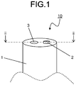
- An electrosurgical knife head 10 includes, as illustrated in FIG. 1 and FIG. 2 , an electrode 2 in a flow channel member 1 having a flow channel 3.
- the electrosurgical knife head 10 illustrated in FIG. 1 is of a monopolar type including one electrode 2, but without being limited thereto, the electrosurgical knife head 10 may be of a bipolar type including a plurality of the electrodes 2.
- a surface 3a of the flow channel 3 in the flow channel member 1 according to the present disclosure has a reduced valley depth Rvk less than a reduced peak height Rpk, the reduced valley depth Rvk and reduced peak height Rpk being found from a roughness profile.
- the reduced valley depth Rvk and reduced peak height Rpk are prescribed by JIS B 0671-2 (2002), and are in accordance with the following definitions.
- a straight line with the least slope is determined as an equivalent straight line, the straight line being a secant of a material ratio curve, the secant being drawn with a material portion difference being 40% at a central portion of the material ratio curve, the central portion including 40% of measurement points of a roughness profile.
- a portion between two height positions where this equivalent straight line intersects the vertical axis at positions where a material portion is 0% and 100% is determined as a roughness core.
- a mean depth of protruding valley portions below the roughness core is the reduced valley depth Rvk.
- a mean height of protruding peak portions above the roughness core is the reduced peak height Rpk.
- the mean depth of the valley portions in the flow channel member 1 according to the present disclosure is small, and thus when blood and pieces of tissue are sucked into the flow channel member 1, clotted blood and pieces of tissue are difficult to be accumulated in the valley portions and the suction force is difficult to be reduced.
- the surface 3a of the flow channel 3 in the flow channel member 1 may have a ratio, Rpk/Rvk, equal to or greater than 1.3, the ratio being between the reduced valley depth Rvk and the reduced peak height Rpk. If such a configuration is satisfied, when blood and pieces of tissue are sucked therein, clotted blood and pieces of tissue are more difficult to be accumulated in the valley portions, and the suction force is thus more difficult to be reduced. When the ratio, Rpk/Rvk, on the surface 3a of the flow channel 3 is equal to or greater than 3.0, the suction force is even more difficult to be reduced.
- the reduced valley depth Rvk may be, for example, equal to or greater than 0.2 ⁇ m and equal to or less than 1.4 ⁇ m.
- the reduced peak height Rpk may be, for example, equal to or greater than 0.7 ⁇ m and equal to or less than 2.3 ⁇ m.
- the surface 3a of the flow channel 3 in the flow channel member 1 according to the present disclosure may have a skewness Rsk that is positive, the skewness Rsk being found from the roughness profile.
- the skewness Rsk is prescribed by JIS B 0601 (2013) and is an index indicating a ratio between the peak portions and the valley portions with respect to a mean height in the roughness profile, the mean height serving as a center line.
- an area of the valley portions is larger than that of the peak portions. Therefore, if such a configuration is satisfied, since the area of the valley portions is large, when blood and pieces of tissue are sucked, clotted blood and pieces of tissue are more difficult to be accumulated in the valley portions, and the suction force is thus more difficult to be reduced.
- the surface 3a of the flow channel 3 in the flow channel member 1 according to the present disclosure may have a ratio, S/RSm, equal to or greater than 0.4 and equal to or less than 0.6, the ratio being between a mean interval S between peaks of the peak portions found from the roughness profile and a mean interval RSm between irregularities found from the roughness profile.
- the mean interval S between the peaks of the peak portions is prescribed by JIS B 0601 (1994), and is an index indicating a mean value of intervals between peaks of peak portions adjacent to each other.
- the mean interval RSm between the irregularities is prescribed by JIS B 0601 (2013), and is an index indicating a mean value of intervals, each of which is an interval between one peak portion and one valley portion adjacent to that peak portion, the interval being the sum of lengths of center lines corresponding to the peak portion and valley portion.
- the suction force is more difficult to be reduced. If the mean interval RSm between the irregularities on the surface 3a of the flow channel 3 in the flow channel member 1 according to the present disclosure is equal to or greater than 15 ⁇ m and equal to or less than 40 ⁇ m, the suction force is more difficult to be reduced.
- the surface 3a of the flow channel 3 in the flow channel member 1 according to the present disclosure may have an arithmetical mean roughness Ra equal to or less than 2 ⁇ m, the arithmetical mean roughness Ra being found from the roughness profile.
- the arithmetical mean roughness Ra, the skewness Rsk, and the mean interval RSm between the irregularities, of the surface 3a of the flow channel 3 in the flow channel member 1 according to the present disclosure are able to be found by measurement conforming to JIS B 0601 (2013); the mean interval S between the peaks of the peak portions is able to be found by measurement conforming to JIS B 0601 (1994); and the reduced valley depth Rvk and reduced peak height Rpk are able to be found by measurement conforming to JIS B 0671-2 (2002).
- a measurement length may be set at 4.8 mm
- a cut-off value may be set at 0.8 mm
- a scanning speed of a stylus having a stylus radius of 2 ⁇ m may be set at 1.0 mm/second. At least three points or more on the surface 3a of the flow channel 3 are measured, and an average value thereof may be found.
- the flow channel member 1 may be formed of any of materials, such as metal and resin, but when the flow channel member 1 is made of ceramic, the flow channel member 1 will be high in heat resistance. In particular, when the ceramic is silicon nitride ceramic, the flow channel member 1 will be high in, not only heat resistance, but also in heat conductivity and mechanical strength. When the flow channel member 1 made of silicon nitride ceramic is used in an electrosurgical knife head, even if heating and cooling are repeated, the flow channel member 1 will be less likely to be damaged and will be high in reliability.
- Silicon nitride ceramic is ceramic containing 70% or more by mass of silicon nitride in 100% by mass of all components forming the ceramic.
- Quality of the material of the flow channel member 1 according to the present disclosure may be checked by the following method. First of all, the flow channel member 1 is measured by use of an X-ray diffractometer (XRD), and a value of 2 ⁇ (where 2 ⁇ is a diffraction angle) obtained thereby is identified by use of JCPDS cards. Subsequently, by use of inductively coupled plasma (ICP) emission spectrophotometer (ICP) or X-ray fluorescence spectrometer (XRF), quantitative analysis for each component forming the flow channel member 1 is performed.
- ICP inductively coupled plasma
- ICP emission spectrophotometer
- XRF X-ray fluorescence spectrometer
- the flow channel member 1 is made of silicon nitride ceramic.
- the flow channel member 1 made of silicon nitride ceramic will be described as an example.
- silicon nitride (Si 3 N 4 ) powder which is the main raw material
- yttrium oxide (Y 2 O 3 ) powder and aluminum oxide (Al 2 O 3 ) powder which are sintering additives
- sintering additives other than yttrium oxide (Y 2 O 3 ) powder and aluminum oxide (Al 2 O 3 ) powder; calcium oxide (CaO) powder, ferric oxide (Fe 2 O 3 ) powder, tungsten oxide (WO 3 ) powder, and/or the like may be added.
- granules are made by spray drying with a spray dryer.
- these granules, thermoplastic resin, wax, and the like are put into a kneader and are kneaded while being heated, and a green body is thereby obtained.
- a green body By the obtained green body being put into a pelletizer, pellets serving as a material for injection molding are obtained.
- the obtained pellets are put into an injection molding machine, injection molding is performed, and a molded body having a through hole, which will become the flow channel 3, is thereby obtained.
- a forming die enabling the through hole, which will become the flow channel 3, to be obtained may be manufactured, and this molding die may be installed in the injection molding machine and injection molding may be performed, based on a general injection molding method. Since surface characteristics of a portion of the molding die will be transferred onto the inner surface of the through hole, the portion forming the through hole; for the reduced valley depth Rvk to be made smaller than the reduced peak height Rpk on the surface of the flow channel, the molded body may be made by use of a molding die having surface characteristics corresponding thereto. The same applies when arbitrary values for the skewness Rsk, the mean interval S between the peaks of the peak portions, the mean interval RSm between the irregularities, and the arithmetical mean roughness Ra are to be obtained for the surface of the flow channel.
- a sintered body is obtained by sintering of the obtained molded body in a nitrogen gas atmosphere with the maximum temperature being held at 1700°C or more and 1800°C or less for 0.5 hours or more and 4 hours or less.
- the surface of the sintered body obtained is subjected to barrel polishing, and the flow channel member 1 according to the present disclosure is thereby obtained. Conditions of the sintering change depending on the shape and size of the product, and thus are adjusted as needed.
- the electrosurgical knife head 10 including the electrode 2 in the flow channel member 1 is able to be obtained.
- silicon nitride powder and yttrium oxide powder, aluminum oxide powder, ferric oxide powder, and tungsten oxide powder, which serve as sintering additives, were prepared. Masses of these different kinds of powder were measured, such that a mixture including 84% by mass of silicon nitride powder, 10% by mass of yttrium oxide powder, 4% by mass of aluminum oxide powder, 1% by mass of ferric oxide powder, and 1% by mass of tungsten oxide powder was obtained; and this mixture was placed, with water added thereto, together with balls, into a mill, was ground and mixed, and was thereby made into slurry.
- this molded body was sintered in a nitrogen gas atmosphere with the maximum temperature being 1750°C and the holding time for the maximum temperature being two hours, and a sintered body was thereby obtained.
- the obtained sintered body was subjected to barrel polishing, and a sample having a diameter of 3.5 mm and a cylindrical shape was each obtained.
- the flow channel of each sample had a diameter of 1.5 mm and a cylindrical shape.
- the reduced valley depth Rvk and the reduced peak height Rpk on the surface of the flow channel were measured based on JIS B 0671-2 (2002).
- the measurement length was set at 4.8 mm
- the cut-off value was set at 0.8 mm
- the scanning speed of the stylus having a stylus radius of 2 ⁇ m was set at 1.0 mm/second. Three points on the surface of the flow channel were measured, and an average value thereof was calculated.
- the samples were then ranked in order from the one with the largest number of particles of silicone in the discharged solution. That is, the sample with the largest number of particles of silicone ranked first, and the sample with the smallest number of particles of silicone ranked last.
- the manufacturing method therefor was the same as the manufacturing method for Sample No. 1 in Example 1, except that surface characteristics of a portion of a molding die installed in the injection molding machine, the portion forming the through hole, were modified such that the surface of the flow channel of each sample had the skewness Rsk listed in Table 2.
- Sample No. 12 is the same as Sample No. 1 in Example 1.
- the manufacturing method therefor was the same as the manufacturing method for Sample No. 13 in Example 2, except that surface characteristics of a portion of a molding die installed in the injection molding machine, the portion forming the through hole, were modified such that the surface of the flow channel of each sample had the mean interval S between peaks of peak portions and mean interval RSm between irregularities both listed in Table 3.
- Sample No. 14 is the same as Sample No. 13 in Example 2.
- Example 1 For each sample obtained, the mean interval S between peaks of peak portions and the mean interval RSm between irregularities on the surface of the flow channel were measured. Conditions for the measurement were the same as those for Example 1 based on JIS B 0601 (1994) and JIS B 0601 (2013). The suction force of each sample was evaluated by the same method as Example 1.
Landscapes
- Health & Medical Sciences (AREA)
- Life Sciences & Earth Sciences (AREA)
- Engineering & Computer Science (AREA)
- Surgery (AREA)
- Heart & Thoracic Surgery (AREA)
- Public Health (AREA)
- Animal Behavior & Ethology (AREA)
- General Health & Medical Sciences (AREA)
- Veterinary Medicine (AREA)
- Biomedical Technology (AREA)
- Nuclear Medicine, Radiotherapy & Molecular Imaging (AREA)
- Plasma & Fusion (AREA)
- Medical Informatics (AREA)
- Molecular Biology (AREA)
- Physics & Mathematics (AREA)
- Otolaryngology (AREA)
- Anesthesiology (AREA)
- Hematology (AREA)
- Neurology (AREA)
- Vascular Medicine (AREA)
- Neurosurgery (AREA)
- Chemical & Material Sciences (AREA)
- Inorganic Chemistry (AREA)
- Epidemiology (AREA)
- Pulmonology (AREA)
- Biophysics (AREA)
- Surgical Instruments (AREA)
- Micromachines (AREA)
Applications Claiming Priority (2)
| Application Number | Priority Date | Filing Date | Title |
|---|---|---|---|
| JP2017065421 | 2017-03-29 | ||
| PCT/JP2018/011788 WO2018181026A1 (ja) | 2017-03-29 | 2018-03-23 | 流路部材およびこれを用いた電気メス用ヘッド |
Publications (2)
| Publication Number | Publication Date |
|---|---|
| EP3603554A1 true EP3603554A1 (de) | 2020-02-05 |
| EP3603554A4 EP3603554A4 (de) | 2021-01-13 |
Family
ID=63675666
Family Applications (1)
| Application Number | Title | Priority Date | Filing Date |
|---|---|---|---|
| EP18775604.4A Withdrawn EP3603554A4 (de) | 2017-03-29 | 2018-03-23 | Strömungskanalelement und kopf für elektrisches skalpell damit |
Country Status (4)
| Country | Link |
|---|---|
| US (1) | US20200188011A1 (de) |
| EP (1) | EP3603554A4 (de) |
| JP (1) | JPWO2018181026A1 (de) |
| WO (1) | WO2018181026A1 (de) |
Cited By (1)
| Publication number | Priority date | Publication date | Assignee | Title |
|---|---|---|---|---|
| EP3845176A4 (de) * | 2018-08-30 | 2022-05-18 | Kyocera Corporation | Kopf eines elektrischen skalpells |
Family Cites Families (6)
| Publication number | Priority date | Publication date | Assignee | Title |
|---|---|---|---|---|
| US6832996B2 (en) * | 1995-06-07 | 2004-12-21 | Arthrocare Corporation | Electrosurgical systems and methods for treating tissue |
| JP4325899B2 (ja) | 2000-10-30 | 2009-09-02 | 京セラ株式会社 | 電気メス用ワンドヘッド |
| US8641686B2 (en) * | 2012-01-20 | 2014-02-04 | Rabie Stephan | Anti-biofilm intravascular catheter |
| JP6049003B2 (ja) * | 2012-04-12 | 2016-12-21 | Towa株式会社 | 梨地面の形成方法、樹脂成形型及び低密着性材料 |
| JP5775989B1 (ja) * | 2013-10-09 | 2015-09-09 | オリンパス株式会社 | 内視鏡用高周波処置具 |
| US9603656B1 (en) * | 2015-10-23 | 2017-03-28 | RELIGN Corporation | Arthroscopic devices and methods |
-
2018
- 2018-03-23 WO PCT/JP2018/011788 patent/WO2018181026A1/ja not_active Ceased
- 2018-03-23 JP JP2019509721A patent/JPWO2018181026A1/ja active Pending
- 2018-03-23 EP EP18775604.4A patent/EP3603554A4/de not_active Withdrawn
- 2018-03-23 US US16/498,004 patent/US20200188011A1/en not_active Abandoned
Cited By (1)
| Publication number | Priority date | Publication date | Assignee | Title |
|---|---|---|---|---|
| EP3845176A4 (de) * | 2018-08-30 | 2022-05-18 | Kyocera Corporation | Kopf eines elektrischen skalpells |
Also Published As
| Publication number | Publication date |
|---|---|
| JPWO2018181026A1 (ja) | 2020-02-06 |
| EP3603554A4 (de) | 2021-01-13 |
| WO2018181026A1 (ja) | 2018-10-04 |
| US20200188011A1 (en) | 2020-06-18 |
Similar Documents
| Publication | Publication Date | Title |
|---|---|---|
| JP6049509B2 (ja) | セラミックヒーター、ヒーター電極及びセラミックヒーターの製法 | |
| RU2542372C2 (ru) | Электродное устройство электрохирургического инструмента | |
| KR101941092B1 (ko) | 세라믹 및 그 제조방법 | |
| KR20100109438A (ko) | 세라믹 히터 및 그 제조 방법 | |
| CN1649039A (zh) | MnZn铁氧体的制造方法 | |
| KR20140069146A (ko) | 세라믹스 원통형 스퍼터링 타겟재 및 그 제조 방법 | |
| EP2154941A1 (de) | Unterdrucksaugdüse | |
| EP3603554A1 (de) | Strömungskanalelement und kopf für elektrisches skalpell damit | |
| JP6623194B2 (ja) | スパークプラグ | |
| CN101888985A (zh) | 注射模制的ptc陶瓷 | |
| CN1590343A (zh) | 铁氧体材料、铁氧体烧结体以及感应体元件 | |
| JP7248687B2 (ja) | 電気メス用ヘッド | |
| JP6546624B2 (ja) | スパークプラグ | |
| CN108369931B (zh) | 流路构件以及半导体模块 | |
| CN105693238A (zh) | 一种具有低介电性能和低损耗的钛酸铋钠基无铅压电铁电材料 | |
| EP3238890B1 (de) | Saugdüse | |
| KR20200049100A (ko) | Ntc 서미스터용 소결체 및 이의 제조방법 | |
| EP1837317A2 (de) | Elektrostatische Einspannvorrichtung und Herstellungsverfahren dafür | |
| US20260022073A1 (en) | Powder for Manufacturing Ceramic Structures and Method for Manufacturing Ceramic Structure Using the same | |
| JP2016064419A (ja) | 摩擦攪拌接合用工具、および、摩擦攪拌接合用工具の製造方法 | |
| CN1201346C (zh) | 氧化物磁性材料、使用该材料的线圈元件和生产氧化物磁性材料和线圈元件的方法 | |
| EP3647296A1 (de) | Aluminiumoxidsubstrat und widerstand damit | |
| JP2015125896A (ja) | アルミナ質焼結体およびこれを備える静電偏向器 | |
| US20180048126A1 (en) | Spark plug | |
| US20250174402A1 (en) | Dielectric ceramic and ceramic capacitor using the same |
Legal Events
| Date | Code | Title | Description |
|---|---|---|---|
| STAA | Information on the status of an ep patent application or granted ep patent |
Free format text: STATUS: THE INTERNATIONAL PUBLICATION HAS BEEN MADE |
|
| PUAI | Public reference made under article 153(3) epc to a published international application that has entered the european phase |
Free format text: ORIGINAL CODE: 0009012 |
|
| STAA | Information on the status of an ep patent application or granted ep patent |
Free format text: STATUS: REQUEST FOR EXAMINATION WAS MADE |
|
| 17P | Request for examination filed |
Effective date: 20191025 |
|
| AK | Designated contracting states |
Kind code of ref document: A1 Designated state(s): AL AT BE BG CH CY CZ DE DK EE ES FI FR GB GR HR HU IE IS IT LI LT LU LV MC MK MT NL NO PL PT RO RS SE SI SK SM TR |
|
| AX | Request for extension of the european patent |
Extension state: BA ME |
|
| DAV | Request for validation of the european patent (deleted) | ||
| DAX | Request for extension of the european patent (deleted) | ||
| A4 | Supplementary search report drawn up and despatched |
Effective date: 20201216 |
|
| RIC1 | Information provided on ipc code assigned before grant |
Ipc: A61B 18/14 20060101AFI20201210BHEP Ipc: A61M 1/00 20060101ALI20201210BHEP |
|
| P01 | Opt-out of the competence of the unified patent court (upc) registered |
Effective date: 20230505 |
|
| STAA | Information on the status of an ep patent application or granted ep patent |
Free format text: STATUS: EXAMINATION IS IN PROGRESS |
|
| 17Q | First examination report despatched |
Effective date: 20240104 |
|
| STAA | Information on the status of an ep patent application or granted ep patent |
Free format text: STATUS: THE APPLICATION HAS BEEN WITHDRAWN |
|
| 18W | Application withdrawn |
Effective date: 20240426 |