EP3602154B1 - Dispositif de clivage de fibre optique et utilisation d'un dispositif de clivage de fibre optique - Google Patents
Dispositif de clivage de fibre optique et utilisation d'un dispositif de clivage de fibre optique Download PDFInfo
- Publication number
- EP3602154B1 EP3602154B1 EP18770335.0A EP18770335A EP3602154B1 EP 3602154 B1 EP3602154 B1 EP 3602154B1 EP 18770335 A EP18770335 A EP 18770335A EP 3602154 B1 EP3602154 B1 EP 3602154B1
- Authority
- EP
- European Patent Office
- Prior art keywords
- fiber
- cleaving
- adhesive
- frame structure
- cleaved
- Prior art date
- Legal status (The legal status is an assumption and is not a legal conclusion. Google has not performed a legal analysis and makes no representation as to the accuracy of the status listed.)
- Active
Links
Images


Classifications
-
- G—PHYSICS
- G02—OPTICS
- G02B—OPTICAL ELEMENTS, SYSTEMS OR APPARATUS
- G02B6/00—Light guides; Structural details of arrangements comprising light guides and other optical elements, e.g. couplings
- G02B6/24—Coupling light guides
- G02B6/36—Mechanical coupling means
- G02B6/3628—Mechanical coupling means for mounting fibres to supporting carriers
- G02B6/3632—Mechanical coupling means for mounting fibres to supporting carriers characterised by the cross-sectional shape of the mechanical coupling means
- G02B6/3636—Mechanical coupling means for mounting fibres to supporting carriers characterised by the cross-sectional shape of the mechanical coupling means the mechanical coupling means being grooves
-
- G—PHYSICS
- G02—OPTICS
- G02B—OPTICAL ELEMENTS, SYSTEMS OR APPARATUS
- G02B6/00—Light guides; Structural details of arrangements comprising light guides and other optical elements, e.g. couplings
- G02B6/24—Coupling light guides
- G02B6/25—Preparing the ends of light guides for coupling, e.g. cutting
-
- G—PHYSICS
- G02—OPTICS
- G02B—OPTICAL ELEMENTS, SYSTEMS OR APPARATUS
- G02B6/00—Light guides; Structural details of arrangements comprising light guides and other optical elements, e.g. couplings
- G02B6/24—Coupling light guides
- G02B6/36—Mechanical coupling means
- G02B6/38—Mechanical coupling means having fibre to fibre mating means
- G02B6/3807—Dismountable connectors, i.e. comprising plugs
- G02B6/3898—Tools, e.g. handheld; Tuning wrenches; Jigs used with connectors, e.g. for extracting, removing or inserting in a panel, for engaging or coupling connectors, for assembling or disassembling components within the connector, for applying clips to hold two connectors together or for crimping
Definitions
- the present invention relates to an optical fiber cleaving device according to claim 1.
- An optical fiber is a thin rod made of a glass-, plastic- or similar material and is most commonly used as a waveguide to transmit light between the two ends of the rod.
- the ends of optical fibers are commonly prepared for a variety of purposes, such as jointing, mounting of a fiber in a component, characterization etc., by a process known as cleaving.
- the fiber to be cleaved is usually clamped by first and second clamping arrangements on opposite sides of a cleaving means for cleaving the fiber.
- One of the clamping arrangements is then moved away from the other for tensioning the fiber clamped therebetween and the movable clamping arrangement is then secured so that the fiber is fixedly held between the clamping arrangements.
- the cleaving means usually has a blade of a hard material, such as diamond, which is brought into a lateral engagement with the tensioned fiber in such a manner as to initiate a fracture which subsequently propagates through the fiber cross-section until the fiber parts.
- a conventional optical fiber cleaving device is already known through the document EP 2 902 823 A1 .
- the device described in said document comprises first (5) and second (6) fiber clamping arrangements configured to clamp and fixedly hold a fiber (4) to be cleaved at opposite sides of a point of the fiber to be hit by cleaving means (3) for cleaving the fiber (see fig. 1 ).
- Each of the clamping arrangements comprises a first member fixedly secured with respect to a frame (2) of the device, and a second member hingedly connected to the first member and movably arranged thereto, between a closed clamping position in which a portion of the fiber is clamped between clamping surfaces of the members, and an open position allowing the fiber to be inserted in or removed from the clamping arrangement.
- the process of cleaving a fiber using such a cleaving device comprises: firstly, placing a portion of the fiber in the first clamping arrangement (5) and transferring this arrangement to the closed clamping position; secondly, placing another portion of the fiber in the second clamping arrangement (6) and transferring this arrangement to the closed clamping position; thirdly, tensioning the fiber by moving one of the clamping arrangements away from the other; and fourthly, cleaving the fiber with the cleaving means (3).
- the object of the present invention is to provide an optical fiber cleaving device of the type defined in the introduction being improved in at least some aspect with respect to such cleaving devices already known, for example through said documents.
- This object is according to the invention obtained by providing such an optical fiber cleaving device with the features of claim 1.
- the invention also relates to use of an optical fiber cleaving device according to the corresponding appended claim 7.
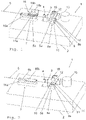
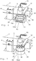
- Optical fiber cleaving devices that do not form part of the claimed invention are illustrated in the appended figures 1-5 while a first clamping arrangement of such a device according to a first and second embodiment of the claimed invention is illustrated in the appended figures 6 and 7 respectively.
- a device according to these embodiments of the invention will now be described while at the same time making reference to all these figures.
- the parts of the fiber cleaving device according to the first and second embodiments of the invention which are not described to be different in the description below are configured in the same way and provide the same function as the corresponding parts of the fiber cleaving device according to the Figure 1 example that does not form part of the claimed invention.
- the optical fiber cleaving device 1 according to a first example not forming part of the claimed invention (shown in figs. 1-4 ) comprises a frame structure 2 provided with cleaving means 3 with a diamond blade 4 configured to cleave an optical fiber 5, and first 6a and second 7 clamping arrangements configured to fixedly hold a fiber to be cleaved at opposite sides of a point of the fiber to be hit by the blade 4 of the cleaving means 3 for cleaving the fiber.
- the cleaving means does not have to include a blade, but could be any type of means suitable for cleaving a fiber, such as means configured to cleave the fiber by a laser beam.
- the first clamping arrangement 6a comprises an element 8a in the form of a small plate, for instance made of plastic, which is removably arranged on a support member 9 of the frame structure 2.
- the element is configured to receive a first portion 5a, usually in the form of an end portion, of a fiber 5 to be cleaved on a surface 10 of the element (see fig. 1 ).
- the element is further configured to receive at least one drop of light-radiation-curing adhesive in the form of UV-curing adhesive 11 on said surface 10, so that at least a part of the first fiber portion 5a is embedded therein (see fig. 2 ).
- the adhesive is applied by means in the form of a dispenser 12 mounted on the frame structure 2 and including a container 13 for storing the adhesive 11 and a nozzle 14 for dispensing adhesive from the container onto said element.
- the adhesive is applied to the surface of the element 8a before the first fiber portion so that the latter may easily be placed in a proper position in the adhesive. This is because it is desirable to have the first fiber portion 5a received in the adhesive 11 on the surface 10 of the element in such a way that the fiber along at least a part of this first portion is completely embedded in adhesive while at the same time the fiber should not be in contact with the surface 10 of the element, but be held at a distance thereto by the adhesive. It is however also possible to firstly place the first fiber portion on the surface of the element and then apply the adhesive thereon.
- the device 1 further comprises means in the form of a UV-lamp 15 configured to emit light in the form of ultraviolet (UV) radiation onto the adhesive 11 received together with the first fiber portion 5a on the element 8a to cure the adhesive so that this firmly binds the first fiber portion to said element.
- the receiving element 8a is configured to be removably arranged on the support member 9 so as to be fixedly secured thereto during cleaving of the fiber 5 whereby the first fiber portion 5a firmly bound to the element by the adhesive will be fixedly held by the first clamping arrangement 6a during the cleaving.
- the means for applying adhesive and light here shown as a stationary mounted dispenser 12 and a "floating" UV-lamp 15, respectively, may each independently be either stationarily mounted on the frame structure 2 of the device 1 or mobile devices to be held and operated by an operator.
- a light-radiationcurable adhesive which is intended to be cured by a different type of light than ultraviolet radiation as well as means configured to emit a different type of light than ultraviolet radiation may be used by a device according to the invention, such as an adhesive curable by blue light and a lamp configured to emit blue light, respectively.
- the second clamping arrangement 7 is formed as a conventional fiber clamp and has two members 16a, 16b provided with clamping surfaces 17a, 17b.
- the members are configured to be movable with respect to each other by means of a hinge connection 18, between a closed clamping position (see fig. 2 ) enabling securing of a second portion 5b of a fiber 5 to be cleaved between the clamping surfaces 17a, 17b, and an open position (see fig. 1 ) allowing the fiber to be inserted in or removed from the second clamping arrangement 7.
- the first 6a and second 7 clamping arrangements of the device 1 are configured to fixedly hold a fiber 5 to be cleaved, at opposite sides of and at a fixed distance to a point of the fiber to be hit by the blade 4 of the cleaving means 3 for cleaving the fiber, by firmly clamping a first 5a and second 5b portion of the fiber, respectively.
- the receiving element 8a is configured to be removed from the support member 9 after cleaving of a fiber 5 and to be discarded together with the first fiber portion 5a and the adhesive 11 received thereon.
- the first clamping arrangement 6a is then provided with a corresponding unused element 8a to receive a first portion of another fiber to be cleaved.
- the receiving element may be removably arranged at the frame structure 2, here on a support member 9 thereof, by means of any suitable securing means, such as bolts, magnets, pins received in holes etc.
- the first clamping arrangement 6b of an optical fiber cleaving device is shown in fig. 5 .
- the receiving element 8b is provided with an elongated recess in the form of an elongated groove 19b disposed at and extending along the entire surface 10 of the element, and the element is configured to receive a first fiber portion 5a together with the adhesive 11 in said groove.
- a groove simplifies the positioning of the first fiber portion on the element 8b and implies a uniform distribution of adhesive around said fiber portion so that this may be firmly bound to the element without being subjected to unevenly distributed radial forces when the adhesive is cured.
- the first clamping arrangement 6c, 6d of an optical fiber cleaving device according to a first and second embodiment of the claimed invention is shown in fig. 6 and 7 , respectively.
- the receiving elements 8c, 8d are according to these embodiments provided with a plurality of recesses in the form of elongated grooves 19c1-2, 19d1-2 disposed at a surface 10 of the respective element.
- Each element 8c, 8d is configured to, when arranged at the frame structure 2, be operable between a first mode in which said surface 10 is firmly fixed with respect to the frame structure so that a first said groove 19c1, 19d1, in which the first portion 5a of a fiber 5 is received and firmly bound by adhesive 11, is held in a fixed position during cleaving of this fiber, and a second mode in which said surface 10 is movable with respect to the frame structure 2, or to at least a part thereof, so as to allow said first groove 19c1, 19d1 to be moved away from said position after cleaving of said fiber and an empty second groove 19c2, 19d2 to be fed to said position in order to receive a first portion of another fiber to be cleaved.
- This operation of the surface provided with grooves 19c1-2, 19d1-2 may be performed by the fact that the respective receiving element is rotatably arranged at the frame structure 2 in such a way that it may be actuated in the second mode to rotate about an axis of rotation so as to feed an empty groove 19c2, 19d2 to said position, and in the first mode to stand still so as to keep a first groove 19c1, 19d1 in said position and thereby fixedly hold a first fiber portion 5a firmly bound by adhesive 11 therein.
- the surface 10 of a receiving element could also be movable with respect to the frame structure 2 by displacing the receiving element thereon in said second mode.
- the grooves 19c1-2 have open ends at said first and second end portion of the element so as to allow easy insertion of a first fiber portion 5a in a groove at the first end portion, and this first fiber portion to protrude out of the groove at the second end portion and away from the element, respectively.
- the grooves could however also be disposed at the surface 10 to extend along at least a part, preferably almost half, of the length of the element 8c.
- the surface of the element may be provided with such grooves extending from both end portions 22, 23 thereof towards the other, so that the element may be turned and arranged to have the second end portion 23 closest to the cleaving means 3 to receive first fiber portions 5a in the grooves provided on this second end portion when all the grooves on the first end portion have been used.
- the receiving element 8d of the first fiber clamping arrangement 6d shown in fig. 7 has the shape of a circular cylinder or disc and the surface 10 provided with grooves 19d1-2 is a substantially flat top surface of the element which extends in a plane at least substantially in parallel with the extension of a fiber 5 to be cleaved during cleaving.
- the element 8d is arranged to have its axis of rotation extending through a center portion 24 of said surface 10 in a direction at least substantially perpendicular to said plane.
- the grooves 19d1-2 disposed at said surface each extend from an outer peripheral edge 25 thereof towards the center portion 24 and have open ends at said edge facing away from the center portion allowing easy insertion of respective first fiber portions 5a therein.
- the number of grooves disposed on the surfaces 10 of the rotatably arranged receiving elements 8c, 8d depends on the intended use of the device, i.e. on the diameters of the fibers to be cleaved etc. This number could be somewhere between 5 or 10 and several hundreds, but is preferably between 50 and 150. Also, the grooves may have a different shape than shown in the figures, such as have a cross-section in the shape of a U or a V, or be provided on the surfaces as a wave-like pattern.
- a method for cleaving an optical fiber 5 using the device is now to be described. This description of the method also serves to further describe the use of a fiber cleaving device 1 according to the invention. Reference will now be made to figs. 1-4 , although any of the first fiber clamping arrangements 6b-d shown in figs. 5-7 may as well be used in this method.
- the use of a fiber cleaving device according to the claimed invention relates to the arrangements shown in Figs. 6 and 7 .
- the fiber to be cleaved is usually stripped, i.e. an outer coating is removed, using a stripping-device and thereafter cleaned with alcohol.
- the second portion 5b of the fiber 5 is then placed in (see fig. 1 ) and firmly clamped (see fig. 2 ) by the second clamping arrangement 7 in a way that has been described above.
- the first fiber portion 5a is thereafter firmly clamped by the first clamping arrangement 6a (see fig.
- the fiber portion held between the first 6a and second 7 clamping arrangements is tensioned by moving at least one of the clamping arrangements away from the other.
- the fiber is then cleaved by the blade 4 of the cleaving means 3 (see fig. 3 ) and the first fiber portion 5a is discarded together with the element 8a on which it is received, by removing the element from the support member 9 of the frame structure 2 (see fig. 4 ).
- the resulting fiber part to be used which includes the second fiber portion 5b, is released from the second clamping arrangement 7 to be moved to a further processing step.
- An unused corresponding receiving element 8a is then arranged on the support member 9 to receive a first portion 5a of another fiber to be cleaved.
- a method for cleaving an optical fiber 5 and thereby achieving a fiber end surface with excellent characteristics is provided, and may be realized by the device according to the invention which enables clamping of the fiber to be cleaved without causing torsional stress in the fiber.
- the use of adhesive which is cured by light radiation, more specifically UV-radiation is particularly important for providing a device which operates quickly, due to the short curing time of such an adhesive.
- the diameter of a fiber to be cleaved is not restricted to be in a specific range, but the optical fiber cleaving device according to the invention could be used for cleaving all fiber diameters presently used, from about 20 ⁇ m to about 4 mm. However, the device is particularly advantageous for cleaving of fibers with diameters less than 1 mm.
- a component such as a receiving element, being arranged at the frame structure is not to be interpreted as that the element must be arranged directly on the frame structure but it could also be arranged on a part of the device secured to the frame structure.
- a device according to the invention could also be provided with more than two fiber clamping arrangements, such as also have a third clamping arrangement mounted on the frame structure and configured to fixedly hold a portion of a fiber during cleaving thereof. Also, more than one fiber clamping arrangement of the device could be configured to clamp a fiber by means of adhesive.
Landscapes
- Physics & Mathematics (AREA)
- General Physics & Mathematics (AREA)
- Optics & Photonics (AREA)
- Optical Couplings Of Light Guides (AREA)
- Mechanical Coupling Of Light Guides (AREA)
- Optical Fibers, Optical Fiber Cores, And Optical Fiber Bundles (AREA)
Claims (7)
- Dispositif (1) de clivage de fibre optique comprenant des moyens (3) configurés pour cliver une fibre (5) optique, un premier (6a-d) et un deuxième (7) agencements de serrage configurés pour maintenir fixement une fibre (5) à cliver en des côtés opposés d'un point de la fibre (5) à frapper par les moyens (3) de clivage pour cliver la fibre (5), dans lequel le premier agencement (6a-d) de serrage comprend un élément (8a-d) configuré pour recevoir un premier tronçon (5a) de la fibre (5) à cliver ensemble avec un adhésif (11) durcissant sous l'effet d'un rayonnement lumineux, le dispositif (1) comprenant en outre des moyens (15) configurés pour appliquer de la lumière à l'adhésif (11) afin de le durcir pour coller fermement le premier tronçon (5a) de fibre à l'élément (8a-d), de manière à maintenir ce premier tronçon (5a) à une distance fixe dudit point pendant le clivage de la fibre (5) par les moyens (3) de clivage, dans lequel au moins des parties des moyens (3) de clivage et du premier (6a-d) et deuxième (7) agencements de serrage sont montées sur une structure (2) de bâti du dispositif (1) de clivage, l'élément (8a-d) de réception est configuré pour être monté de manière amovible sur la structure (2) de bâti d'une manière telle qu'il y soit assujetti fixement pendant un clivage d'une fibre (5) et puisse en être retiré, pour permettre un retrait du premier tronçon (5a) de la fibre après clivage, et dans lequel l'élément (8b-d) de réception est pourvu d'au moins un chambrage (19b, 19c1-2, 19d1-2) oblong et est configuré pour recevoir le premier tronçon (5a) de fibre ensemble avec l'adhésif (11) dans le chambrage (19b, 19c1-2, 19d1-2),
caractérisé en ce que l'élément (8c-d) de réception est pourvu d'une pluralité desdits chambrages (19c1-2, 19d1-2) sous la forme de rainures oblongues disposées sur une surface (10) de l'élément (8c-d) et en ce que l'élément (8c-d) est configuré pour, lorsqu'il monté sur la structure (2) de bâti, pouvoir fonctionner entre un premier mode, dans lequel la surface (10) est fixée solidement par rapport à la structure (2) de bâti, de manière à ce qu'une première rainure, dans laquelle le premier tronçon (5a) d'une fibre (5) est reçu et collé fermement par l'adhésif (11), soit maintenue en une position fixe pendant un clivage de cette fibre (5), et un deuxième mode, dans lequel la surface (10) est mobile par rapport à la structure (2) de bâti, de manière à permettre d'éloigner la première rainure de ladite position après clivage de la fibre (5) et de mettre la une deuxième rainure vide à ladite position afin de recevoir un premier tronçon (5a) d'une autre fibre (5) à cliver. - Dispositif (1) suivant la revendication 1, caractérisé en ce que le dispositif (1) comprend en outre des moyens configurés pour appliquer l'adhésif (11) durcissant sous l'effet d'un rayonnement lumineux à l'élément (8a-d) de réception et ayant un récipient (13) de stockage de l'adhésif (11) et une buse (14) pour dispenser l'adhésif (11) du récipient (13) sur l'élément (8a-d).
- Dispositif suivant la revendication 1 ou 2, caractérisé en ce que l'élément (8c-d) de réception est configuré pour être monté tournant sur la structure (2) de bâti, d'une manière telle que la surface (10) pourvue de rainures soit mobile par rapport à la structure (2) de bâti dans le deuxième mode de l'élément (8c-d) par rotation de l'élément (8c-d) autour d'un axe de rotation.
- Dispositif suivant la revendication 3, caractérisé en ce que la surface (10) est une surface périphérique extérieure de l'élément (8c), qui a sensiblement la forme d'un cylindre de section transversale circulaire, en ce que l'élément (8c) est monté de manière à avoir son axe de rotation s'étendant au moins sensiblement parallèlement à l'étendue d'une fibre (5) à cliver pendant un clivage, et en ce que les rainures disposées à la surface (10) s'étendent chacune au moins sensiblement parallèlement à l'axe de rotation d'une première partie (22) d'extrémité de l'élément (8c) placée la plus près des moyens (3) de clivage et le long d'au moins une partie de l'élément (8c) en direction de sa deuxième partie (23) d'extrémité opposée, et ont des extrémités ouvertes à la première partie (22) d'extrémité de l'élément (8c) faisant face dans la direction s'éloignant de la deuxième partie (23) d'extrémité.
- Dispositif suivant la revendication 3, caractérisé en ce que la surface (10) est une surface sensiblement plane s'étendant dans un plan au moins sensiblement parallèle à l'étendue d'une fibre (5) à cliver pendant un clivage, en ce que l'axe de rotation de l'élément (8d) passe par une partie (24) centrale de la surface (10), dans une direction au moins sensiblement perpendiculaire audit plan, et en ce que les rainures disposées à la surface (10) s'étendent chacune de son bord (25) périphérique extérieur vers la partie (24) centrale, et ont des extrémités ouvertes audit bord (25) faisant face dans la direction s'éloignant de la partie (24) centrale.
- Dispositif suivant l'une quelconque des revendications précédentes, caractérisé en ce que l'adhésif (11) durcissant sous l'effet d'un rayonnement lumineux est un adhésif pouvant durcir par les UV, et en ce que les moyens (15) d'application de lumière sont configurés pour émettre du rayonnement ultraviolet (UV) sur l'adhésif.
- L'utilisation d'un dispositif suivant l'une quelconque des revendications 1 à 6 pour cliver une fibre (5) optique.
Applications Claiming Priority (2)
| Application Number | Priority Date | Filing Date | Title |
|---|---|---|---|
| SE1750328 | 2017-03-20 | ||
| PCT/SE2018/050272 WO2018174789A1 (fr) | 2017-03-20 | 2018-03-20 | Dispositif de clivage de fibre optique, procédé de clivage d'une fibre optique et utilisation d'un dispositif de clivage de fibre optique |
Publications (3)
| Publication Number | Publication Date |
|---|---|
| EP3602154A1 EP3602154A1 (fr) | 2020-02-05 |
| EP3602154A4 EP3602154A4 (fr) | 2020-12-30 |
| EP3602154B1 true EP3602154B1 (fr) | 2022-06-01 |
Family
ID=63586552
Family Applications (1)
| Application Number | Title | Priority Date | Filing Date |
|---|---|---|---|
| EP18770335.0A Active EP3602154B1 (fr) | 2017-03-20 | 2018-03-20 | Dispositif de clivage de fibre optique et utilisation d'un dispositif de clivage de fibre optique |
Country Status (3)
| Country | Link |
|---|---|
| US (1) | US11435527B2 (fr) |
| EP (1) | EP3602154B1 (fr) |
| WO (1) | WO2018174789A1 (fr) |
Families Citing this family (1)
| Publication number | Priority date | Publication date | Assignee | Title |
|---|---|---|---|---|
| CN110657146B (zh) * | 2019-09-12 | 2021-04-06 | 东莞市耀野自动化有限公司 | 一种光学透镜耦合机 |
Family Cites Families (10)
| Publication number | Priority date | Publication date | Assignee | Title |
|---|---|---|---|---|
| DE3429679A1 (de) * | 1984-08-11 | 1986-02-20 | Standard Elektrik Lorenz Ag, 7000 Stuttgart | Verfahren zur herstellung von faserendflaechen |
| DE8904579U1 (de) * | 1989-04-12 | 1989-06-08 | Standard Elektrik Lorenz Ag, 7000 Stuttgart | Vorrichtung zum Trennen von optischen Glasfasern |
| JP3192771B2 (ja) * | 1992-08-21 | 2001-07-30 | 住友大阪セメント株式会社 | 光素子の実装方法 |
| US6711322B1 (en) * | 1998-09-09 | 2004-03-23 | Sumitomo Electric Industries, Ltd. | Optical switch, optical-fiber-arraying-member, production method thereof, and arraying method of optical fibers |
| US20020131729A1 (en) * | 2001-02-16 | 2002-09-19 | Higgins Leo M. | Method and system for automated dynamic fiber optic alignment and assembly |
| TW567345B (en) | 2002-04-19 | 2003-12-21 | Ritek Corp | Fiber array module fabrication method and apparatus thereof |
| EP2460039B1 (fr) | 2009-07-27 | 2019-03-13 | 3SAE Technologies, Inc. | Cliveuse de fibre utilisant un metal liquide et methode de clivage correspondante |
| CN202502267U (zh) * | 2012-02-10 | 2012-10-24 | 一诺仪器(威海)有限公司 | 多功能切割夹具 |
| EP2902823B1 (fr) | 2014-02-03 | 2020-04-01 | Nyfors Teknologi AB | Dispositif de clivage de fibre optique |
| WO2017205865A1 (fr) * | 2016-05-27 | 2017-11-30 | 3Sae Technologies, Inc | Pince sans torsion et clivage de fibre l'utilisant |
-
2018
- 2018-03-20 EP EP18770335.0A patent/EP3602154B1/fr active Active
- 2018-03-20 WO PCT/SE2018/050272 patent/WO2018174789A1/fr not_active Ceased
- 2018-03-20 US US16/495,673 patent/US11435527B2/en active Active
Also Published As
| Publication number | Publication date |
|---|---|
| WO2018174789A1 (fr) | 2018-09-27 |
| US20200033534A1 (en) | 2020-01-30 |
| US11435527B2 (en) | 2022-09-06 |
| EP3602154A4 (fr) | 2020-12-30 |
| EP3602154A1 (fr) | 2020-02-05 |
Similar Documents
| Publication | Publication Date | Title |
|---|---|---|
| US6600866B2 (en) | Filament organizer | |
| EP0211221B1 (fr) | Méthode et appareil pour le couplage de câbles de fibres optiques multiples munies d'un revêtement | |
| US8196793B2 (en) | Optical fiber cutting apparatus and optical fiber cutting method | |
| EP2828695B1 (fr) | Épissure protégée | |
| US6434314B1 (en) | Force equalizing filament clamp | |
| CA1207138A (fr) | Fendage de precision des fibres optiques | |
| WO2002004998A1 (fr) | Porte-conducteur de fibre optique, dispositif de connexion par fusion, dispositif de decoupe et procede de connexion de fibre optique | |
| US20110296965A1 (en) | Method and device for stripping fibers of a fiber bundle | |
| US6666984B2 (en) | Chemical stripping apparatus and method | |
| US6532327B1 (en) | Refractive index grating manufacturing process | |
| EP3602154B1 (fr) | Dispositif de clivage de fibre optique et utilisation d'un dispositif de clivage de fibre optique | |
| US6487939B1 (en) | Apparatus and method for removing coatings from filaments | |
| US20040036188A1 (en) | Recoating of optical fiber | |
| US6783597B2 (en) | Filament recoating apparatus and method | |
| US6665483B2 (en) | Apparatus and method for filament tensioning | |
| US20200326486A1 (en) | Torsion-free clamp and fiber cleaving using same | |
| US6771874B2 (en) | Tension-assisted mounting of fibers on a substrate | |
| KR101159458B1 (ko) | 광섬유 클리빙 장치 | |
| US6503327B2 (en) | Filament recoating apparatus and method | |
| JP2003177253A (ja) | 光ファイバ保持装置、光ファイバグレーティング加工装置、光ファイバグレーティング加工方法および光ファイバグレーティング | |
| KR102485389B1 (ko) | 와이어 삽입장치 | |
| GB2177391A (en) | Method of and apparatus for cleaving optical fibres | |
| JP2007232956A (ja) | 光ファイバテープ心線 | |
| US20150293288A1 (en) | Device and method for processing a light guide for homogeneous coupling-out of light | |
| FR2500935A1 (fr) | Connecteur pour element de cable a fibres optiques et element de cable comportant un tel connecteur |
Legal Events
| Date | Code | Title | Description |
|---|---|---|---|
| STAA | Information on the status of an ep patent application or granted ep patent |
Free format text: STATUS: THE INTERNATIONAL PUBLICATION HAS BEEN MADE |
|
| PUAI | Public reference made under article 153(3) epc to a published international application that has entered the european phase |
Free format text: ORIGINAL CODE: 0009012 |
|
| STAA | Information on the status of an ep patent application or granted ep patent |
Free format text: STATUS: REQUEST FOR EXAMINATION WAS MADE |
|
| 17P | Request for examination filed |
Effective date: 20190916 |
|
| AK | Designated contracting states |
Kind code of ref document: A1 Designated state(s): AL AT BE BG CH CY CZ DE DK EE ES FI FR GB GR HR HU IE IS IT LI LT LU LV MC MK MT NL NO PL PT RO RS SE SI SK SM TR |
|
| AX | Request for extension of the european patent |
Extension state: BA ME |
|
| DAV | Request for validation of the european patent (deleted) | ||
| DAX | Request for extension of the european patent (deleted) | ||
| A4 | Supplementary search report drawn up and despatched |
Effective date: 20201202 |
|
| RIC1 | Information provided on ipc code assigned before grant |
Ipc: G02B 6/25 20060101AFI20201126BHEP Ipc: G02B 6/38 20060101ALN20201126BHEP Ipc: G02B 6/36 20060101ALN20201126BHEP |
|
| RIN1 | Information on inventor provided before grant (corrected) |
Inventor name: BOETTCHER, UWE |
|
| GRAP | Despatch of communication of intention to grant a patent |
Free format text: ORIGINAL CODE: EPIDOSNIGR1 |
|
| STAA | Information on the status of an ep patent application or granted ep patent |
Free format text: STATUS: GRANT OF PATENT IS INTENDED |
|
| RIC1 | Information provided on ipc code assigned before grant |
Ipc: G02B 6/38 20060101ALN20220111BHEP Ipc: G02B 6/36 20060101ALN20220111BHEP Ipc: G02B 6/25 20060101AFI20220111BHEP |
|
| INTG | Intention to grant announced |
Effective date: 20220202 |
|
| GRAA | (expected) grant |
Free format text: ORIGINAL CODE: 0009210 |
|
| GRAS | Grant fee paid |
Free format text: ORIGINAL CODE: EPIDOSNIGR3 |
|
| STAA | Information on the status of an ep patent application or granted ep patent |
Free format text: STATUS: THE PATENT HAS BEEN GRANTED |
|
| AK | Designated contracting states |
Kind code of ref document: B1 Designated state(s): AL AT BE BG CH CY CZ DE DK EE ES FI FR GB GR HR HU IE IS IT LI LT LU LV MC MK MT NL NO PL PT RO RS SE SI SK SM TR |
|
| REG | Reference to a national code |
Ref country code: GB Ref legal event code: FG4D |
|
| REG | Reference to a national code |
Ref country code: AT Ref legal event code: REF Ref document number: 1495783 Country of ref document: AT Kind code of ref document: T Effective date: 20220615 Ref country code: CH Ref legal event code: EP Ref country code: DE Ref legal event code: R096 Ref document number: 602018036247 Country of ref document: DE |
|
| REG | Reference to a national code |
Ref country code: IE Ref legal event code: FG4D |
|
| REG | Reference to a national code |
Ref country code: LT Ref legal event code: MG9D |
|
| REG | Reference to a national code |
Ref country code: NL Ref legal event code: MP Effective date: 20220601 |
|
| PG25 | Lapsed in a contracting state [announced via postgrant information from national office to epo] |
Ref country code: SE Free format text: LAPSE BECAUSE OF FAILURE TO SUBMIT A TRANSLATION OF THE DESCRIPTION OR TO PAY THE FEE WITHIN THE PRESCRIBED TIME-LIMIT Effective date: 20220601 Ref country code: NO Free format text: LAPSE BECAUSE OF FAILURE TO SUBMIT A TRANSLATION OF THE DESCRIPTION OR TO PAY THE FEE WITHIN THE PRESCRIBED TIME-LIMIT Effective date: 20220901 Ref country code: LT Free format text: LAPSE BECAUSE OF FAILURE TO SUBMIT A TRANSLATION OF THE DESCRIPTION OR TO PAY THE FEE WITHIN THE PRESCRIBED TIME-LIMIT Effective date: 20220601 Ref country code: HR Free format text: LAPSE BECAUSE OF FAILURE TO SUBMIT A TRANSLATION OF THE DESCRIPTION OR TO PAY THE FEE WITHIN THE PRESCRIBED TIME-LIMIT Effective date: 20220601 Ref country code: GR Free format text: LAPSE BECAUSE OF FAILURE TO SUBMIT A TRANSLATION OF THE DESCRIPTION OR TO PAY THE FEE WITHIN THE PRESCRIBED TIME-LIMIT Effective date: 20220902 Ref country code: FI Free format text: LAPSE BECAUSE OF FAILURE TO SUBMIT A TRANSLATION OF THE DESCRIPTION OR TO PAY THE FEE WITHIN THE PRESCRIBED TIME-LIMIT Effective date: 20220601 Ref country code: ES Free format text: LAPSE BECAUSE OF FAILURE TO SUBMIT A TRANSLATION OF THE DESCRIPTION OR TO PAY THE FEE WITHIN THE PRESCRIBED TIME-LIMIT Effective date: 20220601 Ref country code: BG Free format text: LAPSE BECAUSE OF FAILURE TO SUBMIT A TRANSLATION OF THE DESCRIPTION OR TO PAY THE FEE WITHIN THE PRESCRIBED TIME-LIMIT Effective date: 20220901 |
|
| REG | Reference to a national code |
Ref country code: AT Ref legal event code: MK05 Ref document number: 1495783 Country of ref document: AT Kind code of ref document: T Effective date: 20220601 |
|
| PG25 | Lapsed in a contracting state [announced via postgrant information from national office to epo] |
Ref country code: RS Free format text: LAPSE BECAUSE OF FAILURE TO SUBMIT A TRANSLATION OF THE DESCRIPTION OR TO PAY THE FEE WITHIN THE PRESCRIBED TIME-LIMIT Effective date: 20220601 Ref country code: PL Free format text: LAPSE BECAUSE OF FAILURE TO SUBMIT A TRANSLATION OF THE DESCRIPTION OR TO PAY THE FEE WITHIN THE PRESCRIBED TIME-LIMIT Effective date: 20220601 Ref country code: LV Free format text: LAPSE BECAUSE OF FAILURE TO SUBMIT A TRANSLATION OF THE DESCRIPTION OR TO PAY THE FEE WITHIN THE PRESCRIBED TIME-LIMIT Effective date: 20220601 |
|
| PG25 | Lapsed in a contracting state [announced via postgrant information from national office to epo] |
Ref country code: NL Free format text: LAPSE BECAUSE OF FAILURE TO SUBMIT A TRANSLATION OF THE DESCRIPTION OR TO PAY THE FEE WITHIN THE PRESCRIBED TIME-LIMIT Effective date: 20220601 |
|
| PG25 | Lapsed in a contracting state [announced via postgrant information from national office to epo] |
Ref country code: SM Free format text: LAPSE BECAUSE OF FAILURE TO SUBMIT A TRANSLATION OF THE DESCRIPTION OR TO PAY THE FEE WITHIN THE PRESCRIBED TIME-LIMIT Effective date: 20220601 Ref country code: SK Free format text: LAPSE BECAUSE OF FAILURE TO SUBMIT A TRANSLATION OF THE DESCRIPTION OR TO PAY THE FEE WITHIN THE PRESCRIBED TIME-LIMIT Effective date: 20220601 Ref country code: RO Free format text: LAPSE BECAUSE OF FAILURE TO SUBMIT A TRANSLATION OF THE DESCRIPTION OR TO PAY THE FEE WITHIN THE PRESCRIBED TIME-LIMIT Effective date: 20220601 Ref country code: PT Free format text: LAPSE BECAUSE OF FAILURE TO SUBMIT A TRANSLATION OF THE DESCRIPTION OR TO PAY THE FEE WITHIN THE PRESCRIBED TIME-LIMIT Effective date: 20221003 Ref country code: EE Free format text: LAPSE BECAUSE OF FAILURE TO SUBMIT A TRANSLATION OF THE DESCRIPTION OR TO PAY THE FEE WITHIN THE PRESCRIBED TIME-LIMIT Effective date: 20220601 Ref country code: CZ Free format text: LAPSE BECAUSE OF FAILURE TO SUBMIT A TRANSLATION OF THE DESCRIPTION OR TO PAY THE FEE WITHIN THE PRESCRIBED TIME-LIMIT Effective date: 20220601 Ref country code: AT Free format text: LAPSE BECAUSE OF FAILURE TO SUBMIT A TRANSLATION OF THE DESCRIPTION OR TO PAY THE FEE WITHIN THE PRESCRIBED TIME-LIMIT Effective date: 20220601 |
|
| PG25 | Lapsed in a contracting state [announced via postgrant information from national office to epo] |
Ref country code: IS Free format text: LAPSE BECAUSE OF FAILURE TO SUBMIT A TRANSLATION OF THE DESCRIPTION OR TO PAY THE FEE WITHIN THE PRESCRIBED TIME-LIMIT Effective date: 20221001 |
|
| REG | Reference to a national code |
Ref country code: DE Ref legal event code: R097 Ref document number: 602018036247 Country of ref document: DE |
|
| PG25 | Lapsed in a contracting state [announced via postgrant information from national office to epo] |
Ref country code: AL Free format text: LAPSE BECAUSE OF FAILURE TO SUBMIT A TRANSLATION OF THE DESCRIPTION OR TO PAY THE FEE WITHIN THE PRESCRIBED TIME-LIMIT Effective date: 20220601 |
|
| PLBE | No opposition filed within time limit |
Free format text: ORIGINAL CODE: 0009261 |
|
| STAA | Information on the status of an ep patent application or granted ep patent |
Free format text: STATUS: NO OPPOSITION FILED WITHIN TIME LIMIT |
|
| PG25 | Lapsed in a contracting state [announced via postgrant information from national office to epo] |
Ref country code: DK Free format text: LAPSE BECAUSE OF FAILURE TO SUBMIT A TRANSLATION OF THE DESCRIPTION OR TO PAY THE FEE WITHIN THE PRESCRIBED TIME-LIMIT Effective date: 20220601 |
|
| 26N | No opposition filed |
Effective date: 20230302 |
|
| PG25 | Lapsed in a contracting state [announced via postgrant information from national office to epo] |
Ref country code: SI Free format text: LAPSE BECAUSE OF FAILURE TO SUBMIT A TRANSLATION OF THE DESCRIPTION OR TO PAY THE FEE WITHIN THE PRESCRIBED TIME-LIMIT Effective date: 20220601 |
|
| PG25 | Lapsed in a contracting state [announced via postgrant information from national office to epo] |
Ref country code: MC Free format text: LAPSE BECAUSE OF FAILURE TO SUBMIT A TRANSLATION OF THE DESCRIPTION OR TO PAY THE FEE WITHIN THE PRESCRIBED TIME-LIMIT Effective date: 20220601 |
|
| REG | Reference to a national code |
Ref country code: CH Ref legal event code: PL |
|
| REG | Reference to a national code |
Ref country code: BE Ref legal event code: MM Effective date: 20230331 |
|
| PG25 | Lapsed in a contracting state [announced via postgrant information from national office to epo] |
Ref country code: LU Free format text: LAPSE BECAUSE OF NON-PAYMENT OF DUE FEES Effective date: 20230320 |
|
| REG | Reference to a national code |
Ref country code: IE Ref legal event code: MM4A |
|
| PG25 | Lapsed in a contracting state [announced via postgrant information from national office to epo] |
Ref country code: LI Free format text: LAPSE BECAUSE OF NON-PAYMENT OF DUE FEES Effective date: 20230331 Ref country code: IT Free format text: LAPSE BECAUSE OF FAILURE TO SUBMIT A TRANSLATION OF THE DESCRIPTION OR TO PAY THE FEE WITHIN THE PRESCRIBED TIME-LIMIT Effective date: 20220601 Ref country code: IE Free format text: LAPSE BECAUSE OF NON-PAYMENT OF DUE FEES Effective date: 20230320 Ref country code: CH Free format text: LAPSE BECAUSE OF NON-PAYMENT OF DUE FEES Effective date: 20230331 |
|
| PG25 | Lapsed in a contracting state [announced via postgrant information from national office to epo] |
Ref country code: BE Free format text: LAPSE BECAUSE OF NON-PAYMENT OF DUE FEES Effective date: 20230331 |
|
| PG25 | Lapsed in a contracting state [announced via postgrant information from national office to epo] |
Ref country code: BG Free format text: LAPSE BECAUSE OF FAILURE TO SUBMIT A TRANSLATION OF THE DESCRIPTION OR TO PAY THE FEE WITHIN THE PRESCRIBED TIME-LIMIT Effective date: 20220601 |
|
| PG25 | Lapsed in a contracting state [announced via postgrant information from national office to epo] |
Ref country code: BG Free format text: LAPSE BECAUSE OF FAILURE TO SUBMIT A TRANSLATION OF THE DESCRIPTION OR TO PAY THE FEE WITHIN THE PRESCRIBED TIME-LIMIT Effective date: 20220601 |
|
| PG25 | Lapsed in a contracting state [announced via postgrant information from national office to epo] |
Ref country code: CY Free format text: LAPSE BECAUSE OF FAILURE TO SUBMIT A TRANSLATION OF THE DESCRIPTION OR TO PAY THE FEE WITHIN THE PRESCRIBED TIME-LIMIT; INVALID AB INITIO Effective date: 20180320 |
|
| PG25 | Lapsed in a contracting state [announced via postgrant information from national office to epo] |
Ref country code: HU Free format text: LAPSE BECAUSE OF FAILURE TO SUBMIT A TRANSLATION OF THE DESCRIPTION OR TO PAY THE FEE WITHIN THE PRESCRIBED TIME-LIMIT; INVALID AB INITIO Effective date: 20180320 |
|
| PG25 | Lapsed in a contracting state [announced via postgrant information from national office to epo] |
Ref country code: TR Free format text: LAPSE BECAUSE OF FAILURE TO SUBMIT A TRANSLATION OF THE DESCRIPTION OR TO PAY THE FEE WITHIN THE PRESCRIBED TIME-LIMIT Effective date: 20220601 |
|
| PGFP | Annual fee paid to national office [announced via postgrant information from national office to epo] |
Ref country code: GB Payment date: 20260317 Year of fee payment: 9 |
|
| PGFP | Annual fee paid to national office [announced via postgrant information from national office to epo] |
Ref country code: DE Payment date: 20260318 Year of fee payment: 9 |
|
| PGFP | Annual fee paid to national office [announced via postgrant information from national office to epo] |
Ref country code: FR Payment date: 20260317 Year of fee payment: 9 |