EP3601828B1 - Isoliervorrichtung mit ausgewähltem winkel zwischen federanschlag und dämpfungselement - Google Patents
Isoliervorrichtung mit ausgewähltem winkel zwischen federanschlag und dämpfungselement Download PDFInfo
- Publication number
- EP3601828B1 EP3601828B1 EP18776815.5A EP18776815A EP3601828B1 EP 3601828 B1 EP3601828 B1 EP 3601828B1 EP 18776815 A EP18776815 A EP 18776815A EP 3601828 B1 EP3601828 B1 EP 3601828B1
- Authority
- EP
- European Patent Office
- Prior art keywords
- hub
- pulley
- spring
- isolation
- torque
- Prior art date
- Legal status (The legal status is an assumption and is not a legal conclusion. Google has not performed a legal analysis and makes no representation as to the accuracy of the status listed.)
- Active
Links
- 238000002955 isolation Methods 0.000 title claims description 142
- 238000013016 damping Methods 0.000 title claims description 103
- 230000005540 biological transmission Effects 0.000 claims description 15
- 238000000034 method Methods 0.000 claims description 13
- 239000000463 material Substances 0.000 description 5
- 239000004677 Nylon Substances 0.000 description 2
- 230000001133 acceleration Effects 0.000 description 2
- 230000009286 beneficial effect Effects 0.000 description 2
- 230000006835 compression Effects 0.000 description 2
- 238000007906 compression Methods 0.000 description 2
- 230000001419 dependent effect Effects 0.000 description 2
- 238000010586 diagram Methods 0.000 description 2
- 229920001778 nylon Polymers 0.000 description 2
- 229910000639 Spring steel Inorganic materials 0.000 description 1
- 229910000831 Steel Inorganic materials 0.000 description 1
- XAGFODPZIPBFFR-UHFFFAOYSA-N aluminium Chemical compound [Al] XAGFODPZIPBFFR-UHFFFAOYSA-N 0.000 description 1
- 229910052782 aluminium Inorganic materials 0.000 description 1
- 230000004048 modification Effects 0.000 description 1
- 238000012986 modification Methods 0.000 description 1
- 230000010355 oscillation Effects 0.000 description 1
- ISWSIDIOOBJBQZ-UHFFFAOYSA-N phenol group Chemical group C1(=CC=CC=C1)O ISWSIDIOOBJBQZ-UHFFFAOYSA-N 0.000 description 1
- 239000010959 steel Substances 0.000 description 1
- 239000013598 vector Substances 0.000 description 1
Images


Classifications
-
- F—MECHANICAL ENGINEERING; LIGHTING; HEATING; WEAPONS; BLASTING
- F16—ENGINEERING ELEMENTS AND UNITS; GENERAL MEASURES FOR PRODUCING AND MAINTAINING EFFECTIVE FUNCTIONING OF MACHINES OR INSTALLATIONS; THERMAL INSULATION IN GENERAL
- F16H—GEARING
- F16H7/00—Gearings for conveying rotary motion by endless flexible members
- F16H7/18—Means for guiding or supporting belts, ropes, or chains
- F16H7/20—Mountings for rollers or pulleys
-
- F—MECHANICAL ENGINEERING; LIGHTING; HEATING; WEAPONS; BLASTING
- F16—ENGINEERING ELEMENTS AND UNITS; GENERAL MEASURES FOR PRODUCING AND MAINTAINING EFFECTIVE FUNCTIONING OF MACHINES OR INSTALLATIONS; THERMAL INSULATION IN GENERAL
- F16H—GEARING
- F16H55/00—Elements with teeth or friction surfaces for conveying motion; Worms, pulleys or sheaves for gearing mechanisms
- F16H55/32—Friction members
- F16H55/36—Pulleys
-
- B—PERFORMING OPERATIONS; TRANSPORTING
- B60—VEHICLES IN GENERAL
- B60K—ARRANGEMENT OR MOUNTING OF PROPULSION UNITS OR OF TRANSMISSIONS IN VEHICLES; ARRANGEMENT OR MOUNTING OF PLURAL DIVERSE PRIME-MOVERS IN VEHICLES; AUXILIARY DRIVES FOR VEHICLES; INSTRUMENTATION OR DASHBOARDS FOR VEHICLES; ARRANGEMENTS IN CONNECTION WITH COOLING, AIR INTAKE, GAS EXHAUST OR FUEL SUPPLY OF PROPULSION UNITS IN VEHICLES
- B60K25/00—Auxiliary drives
- B60K25/02—Auxiliary drives directly from an engine shaft
-
- F—MECHANICAL ENGINEERING; LIGHTING; HEATING; WEAPONS; BLASTING
- F02—COMBUSTION ENGINES; HOT-GAS OR COMBUSTION-PRODUCT ENGINE PLANTS
- F02B—INTERNAL-COMBUSTION PISTON ENGINES; COMBUSTION ENGINES IN GENERAL
- F02B67/00—Engines characterised by the arrangement of auxiliary apparatus not being otherwise provided for, e.g. the apparatus having different functions; Driving auxiliary apparatus from engines, not otherwise provided for
- F02B67/04—Engines characterised by the arrangement of auxiliary apparatus not being otherwise provided for, e.g. the apparatus having different functions; Driving auxiliary apparatus from engines, not otherwise provided for of mechanically-driven auxiliary apparatus
- F02B67/06—Engines characterised by the arrangement of auxiliary apparatus not being otherwise provided for, e.g. the apparatus having different functions; Driving auxiliary apparatus from engines, not otherwise provided for of mechanically-driven auxiliary apparatus driven by means of chains, belts, or like endless members
-
- F—MECHANICAL ENGINEERING; LIGHTING; HEATING; WEAPONS; BLASTING
- F16—ENGINEERING ELEMENTS AND UNITS; GENERAL MEASURES FOR PRODUCING AND MAINTAINING EFFECTIVE FUNCTIONING OF MACHINES OR INSTALLATIONS; THERMAL INSULATION IN GENERAL
- F16D—COUPLINGS FOR TRANSMITTING ROTATION; CLUTCHES; BRAKES
- F16D41/00—Freewheels or freewheel clutches
- F16D41/20—Freewheels or freewheel clutches with expandable or contractable clamping ring or band
- F16D41/206—Freewheels or freewheel clutches with expandable or contractable clamping ring or band having axially adjacent coils, e.g. helical wrap-springs
-
- F—MECHANICAL ENGINEERING; LIGHTING; HEATING; WEAPONS; BLASTING
- F16—ENGINEERING ELEMENTS AND UNITS; GENERAL MEASURES FOR PRODUCING AND MAINTAINING EFFECTIVE FUNCTIONING OF MACHINES OR INSTALLATIONS; THERMAL INSULATION IN GENERAL
- F16F—SPRINGS; SHOCK-ABSORBERS; MEANS FOR DAMPING VIBRATION
- F16F15/00—Suppression of vibrations in systems; Means or arrangements for avoiding or reducing out-of-balance forces, e.g. due to motion
- F16F15/10—Suppression of vibrations in rotating systems by making use of members moving with the system
- F16F15/12—Suppression of vibrations in rotating systems by making use of members moving with the system using elastic members or friction-damping members, e.g. between a rotating shaft and a gyratory mass mounted thereon
- F16F15/121—Suppression of vibrations in rotating systems by making use of members moving with the system using elastic members or friction-damping members, e.g. between a rotating shaft and a gyratory mass mounted thereon using springs as elastic members, e.g. metallic springs
- F16F15/1216—Torsional springs, e.g. torsion bar or torsionally-loaded coil springs
-
- F—MECHANICAL ENGINEERING; LIGHTING; HEATING; WEAPONS; BLASTING
- F16—ENGINEERING ELEMENTS AND UNITS; GENERAL MEASURES FOR PRODUCING AND MAINTAINING EFFECTIVE FUNCTIONING OF MACHINES OR INSTALLATIONS; THERMAL INSULATION IN GENERAL
- F16F—SPRINGS; SHOCK-ABSORBERS; MEANS FOR DAMPING VIBRATION
- F16F15/00—Suppression of vibrations in systems; Means or arrangements for avoiding or reducing out-of-balance forces, e.g. due to motion
- F16F15/10—Suppression of vibrations in rotating systems by making use of members moving with the system
- F16F15/12—Suppression of vibrations in rotating systems by making use of members moving with the system using elastic members or friction-damping members, e.g. between a rotating shaft and a gyratory mass mounted thereon
- F16F15/129—Suppression of vibrations in rotating systems by making use of members moving with the system using elastic members or friction-damping members, e.g. between a rotating shaft and a gyratory mass mounted thereon characterised by friction-damping means
-
- B—PERFORMING OPERATIONS; TRANSPORTING
- B60—VEHICLES IN GENERAL
- B60K—ARRANGEMENT OR MOUNTING OF PROPULSION UNITS OR OF TRANSMISSIONS IN VEHICLES; ARRANGEMENT OR MOUNTING OF PLURAL DIVERSE PRIME-MOVERS IN VEHICLES; AUXILIARY DRIVES FOR VEHICLES; INSTRUMENTATION OR DASHBOARDS FOR VEHICLES; ARRANGEMENTS IN CONNECTION WITH COOLING, AIR INTAKE, GAS EXHAUST OR FUEL SUPPLY OF PROPULSION UNITS IN VEHICLES
- B60K25/00—Auxiliary drives
- B60K25/02—Auxiliary drives directly from an engine shaft
- B60K2025/022—Auxiliary drives directly from an engine shaft by a mechanical transmission
-
- F—MECHANICAL ENGINEERING; LIGHTING; HEATING; WEAPONS; BLASTING
- F16—ENGINEERING ELEMENTS AND UNITS; GENERAL MEASURES FOR PRODUCING AND MAINTAINING EFFECTIVE FUNCTIONING OF MACHINES OR INSTALLATIONS; THERMAL INSULATION IN GENERAL
- F16H—GEARING
- F16H55/00—Elements with teeth or friction surfaces for conveying motion; Worms, pulleys or sheaves for gearing mechanisms
- F16H55/32—Friction members
- F16H55/36—Pulleys
- F16H2055/366—Pulleys with means providing resilience or vibration damping
Definitions
- This invention relates to isolation devices such as isolators and decouplers, and in particular to isolation devices that are used on an accessory drive shaft on a vehicular engine where damping of the isolation device is required.
- Isolation devices such as isolators (with little or no overrunning capability) and decouplers (with overrunning capability via a one-way clutch) are known devices that are installed on accessory drive shafts on vehicular engines for reducing the transmission of torsional vibrations from the crankshaft of the engine to the accessory driven by the crankshaft through an accessory drive belt. It is also known to install isolation devices on the crankshaft itself to reduce the transmission of torsional vibrations into the accessory drive belt itself. It is known that certain accessories, such as the alternator, can cause an isolation device to go into resonance during operation, and it has been found that damping is advantageous in order to inhibit this from occurring. However, further improvements in the performance of isolation devices would be beneficial.
- the device includes a hub configured to couple to the shaft, a pulley rotatably coupled to the hub that includes a power transmitting surface configured to engage the belt, an isolation spring to transfer a rotational load from one of the pulley and the hub to the other of the pulley and the hub, a one-way clutch to permit overrunning of one of the pulley and the hub relative to the other of the pulley and the hub in a first direction, and a damping member positioned to be driven into frictional engagement with a friction surface by a force from the isolation spring acting on the damping member that varies based on the rotational load transferred by the isolation spring.
- FIG 1 shows an engine 10 for a vehicle.
- the engine 10 includes a crankshaft 12 which drives an endless drive member 14, which may be, for example, a belt.
- the endless drive member 14 may be referred to in the present invention as the belt 14 for greater readability, however it will be understood that it could alternatively be any other suitable type of endless drive member.
- the engine 10 drives a plurality of accessories 16, such as an alternator, which is identified at 16a.
- Each accessory 16 includes an input drive shaft 15 with a pulley 13 thereon, which is driven by the belt 14.
- An isolation device 20 is provided instead of a pulley, between the belt 14 and the input shaft 15 of any one or more of the belt driven accessories 16.
- the isolation device 20 permits the transfer of torque from the belt 14 to the alternator 16a, while isolating the alternator from torsional vibrations that are transmitted into the belt 14 from the crankshaft 12.
- the isolation device 20 provides damping that is dependent on the amount of torque being transferred between the belt 14 and the shaft 15 and that is very low or substantially zero for torques below a selected torque value.
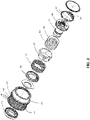
- the isolation device 20 is shown in perspective view in Figure 2 .
- the isolation device 20 may be any suitable type of isolation device, such as an isolator, or a decoupler.
- the isolation device is a decoupler and reference to the 'decoupler 20' may be made throughout the present invention, for greater readability.
- the decoupler 20 could alternatively be any other suitable type of isolation device, such as an isolator that is not equipped with a one-way overrunning clutch.
- the decoupler 20 includes a hub 22, a pulley 24, a first bearing member 26, a second bearing member 27, an isolation spring 28, a carrier 30, a one-way clutch 31 and a damping member 32.
- the hub 22 is mountable to the accessory shaft (e.g. the alternator shaft 15a in Figure 1 ) in any suitable way.
- the hub 22 may have a shaft-mounting aperture 36 ( Figure 4 ) therethrough that is used for the mounting of the hub 22 to the end of the alternator shaft 15, for co-rotation of the hub 22 and the alternator shaft 15.
- the pulley 24 is rotatable relative to the hub 22.
- the pulley 24 has an outer surface 40 which is configured for engagement with the belt 14.
- the outer surface 40 is shown as having grooves 42.
- the belt 14 may thus be a multiple-V belt. It will be understood however, that the outer surface 40 of the pulley 24 may have any other suitable configuration and the belt 14 need not be a multiple-V belt.
- the pulley 24 could have a single groove and the belt 14 could be a single V belt, or the pulley 24 may have a generally flat portion for engaging a flat belt 14.
- the pulley 24 further includes an inner surface 43 which is described further below.
- the pulley 24 may be made from any suitable material, such as a steel, or aluminum, or in some cases a polymeric material, such as certain types of nylon, phenolic or other materials.
- the first bearing member 26 rotatably supports the pulley 24 on the hub 22 at a first (proximal) axial end 44 of the pulley 24.
- the first bearing member 26 may be a bearing (e.g. a ball bearing) or a bushing.
- the second bearing member 27 also rotatably supports the pulley 24 on the hub 22, but at a second (distal) axial end 45 of the pulley 24.
- the second bearing member is made up of bushing projections that extend out from the damping member 32.
- the isolation spring 28 is provided to accommodate oscillations in the speed of the belt 14 relative to the alternator shaft 15a, which result from torsional vibrations.
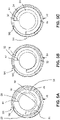
- the isolation spring 28 in the embodiment shown is a helical torsion spring that has a first helical end 50 that is held in an annular slot 51 ( Figure 5A ) and that abuts a first spring end engagement feature 52 ( Figure 5A ), which is in the example shown, a radially extending driver wall on the hub 22.
- the isolation spring 28 has a second helical end 53 ( Figure 3 ) that engages a second spring end engagement feature 54 (which may also be a radially extending driver wall) on the carrier 30.
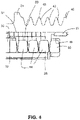
- the isolation spring 28 has a plurality of coils 58 between the first and second ends 50 and 53, and has a radially outer surface 59.
- the coils 58 are preferably spaced apart by a selected amount and the isolation spring 28 is preferably under a selected amount of axial compression to ensure that the first and second helical ends 50 and 53 of the spring 28 are abutted with the respective walls on the carrier 30 and hub 22.
- An example of a suitable engagement between the isolation spring 28, the hub 22 and the carrier 30 is shown and described in US Patent 7,712,592 .
- a thrust plate 73 may be provided to receive the axial thrust force of the carrier 30 resulting from the axial compression of the spring 28.
- the isolation spring 28 may be made from any suitable material, such as a suitable spring steel.
- the isolation spring 28 may have any suitable cross-sectional shape.
- the isolation spring 28 is shown as having a generally rectangular cross-sectional shape, which provides it with a relatively high torsional resistance (i.e. spring rate) for a given occupied volume.
- spring rate torsional resistance
- a suitable spring rate may be obtained with other cross-sectional shapes, such as a circular cross-sectional shape or a square cross-sectional shape.
- the one-way clutch 31 may be any suitable type of one-way clutch such as a wrap spring clutch.
- the one-way clutch 31 may be referred to herein as the 'wrap spring clutch 31', but it will be understood that the one-way clutch 31 could be any other suitable type of one-way clutch.
- the wrap spring clutch 31 When actuated, the wrap spring clutch 31 expands radially to engage the inner surface 43 in order to couple the pulley 24 and hub 22 together.
- the wrap spring clutch 31 has a first end 60 that is engaged in a slot in the carrier 30 so as to fixedly connect the first end 60 to the carrier 30 in engagement with a radially-extending clutch drive wall 62 on the carrier 30.
- the wrap spring clutch 31 has a second end 64 that may be free floating, and has a plurality of coils 66 between the first 60 and second ends 64.
- the carrier 30 may be made from any suitable material such as, for example, a suitable nylon or the like.
- the carrier provides an operative connection between the isolation spring 28 and the wrap spring clutch 31 for torque transmission therebetween, as is known in the art.
- the first end 60 of the wrap spring clutch 31 transmits the torque from the pulley to the carrier 30.
- the carrier 30 transmits the torque into the isolation spring 28.
- the isolation spring 28 transmits torque from the carrier 30 into the hub 22.
- the hub 22 is brought up to the speed of the pulley 24.
- the wrap spring clutch 31 operatively connects the pulley 24 to the carrier 30 and therefore to the hub 22.
- Torque transfer through the isolation spring 28 drives a change in radius of the helical coils 58.
- the isolation spring 28 expands radially during torque transfer therethrough.
- an optional torque limiter sleeve 68 may be provided to limit the amount of radial expansion that the isolation spring 28 can incur.
- the torque limiter sleeve 68 is, in the embodiment shown, a helical member itself, although it could have any other suitable configuration such as a hollow cylindrical shape.
- An example of a hollow cylindrical sleeve is shown in Figure 3 .
- the isolation spring 28 expands until the isolation spring 28 is constrained by the sleeve 57.
- An example of a suitable sleeve 68 is shown and described in US Patent 7,766,774 .
- the damping member 32 is fixed rotationally relative to one of the hub 22 and the pulley 24 and is engageable frictionally with the other of the hub 22 and the pulley 24, and is positioned radially between the isolation spring 28 and said other of the hub 22 and the pulley 24.
- the damping member 32 is positioned radially between the isolation spring 28 and the pulley 24, and is fixed rotationally relative to the hub 22. More specifically, the damping member 32 sits in a window 33 in an outer wall 99 of the hub 22 that in part defines the slot 51.
- the damping member 32 has a first angular end 70 and a second angular end 72 and has a selected angular length LD between the first and second angular ends 70 and 72, as shown in Figure 5A .
- a selected angular length LD between the first and second angular ends 70 and 72, as shown in Figure 5A .
- torque transmission through the isolation spring increases, irrespective of hub load on the pulley 24, beyond the selected non-zero torque, the radial force to press the damping member 32 against said other of the hub 22 and the pulley 24 increases, so as to generate increasing frictional damping.
- Markers on the pulley 24 and hub 22 are shown at M1 and M2, respectively, so that the relative rotational positions of the pulley 24 and hub 22 can be seen in Figures 5A-5C .
- the position of the damping member 32 relative to the first spring end 50 of the isolation spring 28 determines the amount of torque that is transferred between the pulley 24 and the hub 22 before any damping occurs through the damping member 32. It has been found that the initial contact of the isolation spring 28 with the wall of the slot of the hub 22 occurs at 118 degrees from the first end 50 of the isolation spring 28, or alternatively worded, from the first spring end engagement feature 52. The wall of the slot 51 in the hub 22 is shown at 99. In the embodiment in which the damping member 32 has a length of 84 degrees, as long as the damping member 32 is positioned with its centre between 90 and 160 degrees, engagement of the isolation spring 28 with the damping member 32 will occur at 118 degrees from the first spring end 50.
- the damping member 32 is positioned with its centre greater than 160 degrees from the first spring end 50, then the first end 70 of the damping member 32 is positioned farther than 118 degrees from the first spring end 50. Accordingly, the isolation spring 28 will engage the wall of the hub 22 and some portion of the isolation spring 28 will engage the first end 70 of the damping member 32. However, because some portion of the isolation spring is also engaged with the wall of the hub 22, the force of engagement of the isolation spring 28 on the damping member 32 is lower than if the damping member 32 were positioned within 118 degrees of the first spring end 50. As the damping member 32 is positioned farther and farther from the first end 50 of the spring 28, the force on the damping member initially applied by the spring 28 is lower and lower.
- the force on the damping member 32 is directly related to the friction force (i.e. the damping force) that is present between the damping member 32 and the pulley surface. Accordingly, the position of the damping member 32 directly controls the damping force that is generated between the pulley 24 and the hub 22.
- the damping member 32 is positioned within the range of 90 degrees to 160 degrees inclusive, so as to be directly engaged by the isolation spring 28 upon torque transfer through the decoupler 20.
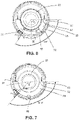
- the damping member has its centre position at 90 degrees. The angular distance of the first spring end 50 to the centre of the damping member 32 may be shown at a. Based on the angle of engagement of 118 degrees, the normal force FN1 is applied at an angle of 28 degrees from the direction line of the forces FR.
- the damping member 32 is positioned greater than 160 degrees and less than or equal to 220 degrees from the first spring end 50.
- the engagement of the spring 28 with the damping member will occur at the first end 70 of the damping member 32 and not at 118 degrees.
- the engagement will occur at a-42 degrees (in the present embodiment where the damping member is 84 degrees in angular length).
- the angle between the normal force (shown as FN2) and the direction lines of the forces FR (which remain the same as the forces FR in Figure 6 for comparison purposes), is a-132 degrees.
- FN2 FN1.
- a 160 degrees
- FN2 FN1.
- FIG. 8 shows a graph of the isolation factor of the decoupler 20 relative to torsional acceleration on the pulley 24, with varying torques being applied and varying values of Ff/FN (where Ff is the force of friction (i.e. the damping force) and FN as noted above is the normal force on the damping member 32).
- Figures 9A and 9B illustrate the amount of damping torque that occurs for two different positions of the damping member.
- Figure 9A represents the damping torque when the damping member 32 is within the range of 90 to 160 degrees.
- Figure 9B represents the damping torque when the damping member 32 is at 200 degrees. It will be understood in general that, when the position of the damping member 32 is given in degrees, it is intended to mean the number of degrees from the first end 50 of the isolation spring 28.
- FIG 11 shows the relationship between the torque transfer at which damping begins in relation to the position of the damping member 32.
- the angle a of the centre of the damping member 32 is less than or equal to 160 degrees, the torque at which some damping occurs is zero. In other words, some damping occurs at all torques.
- the angle a is greater than 160 degrees the torque upon which damping starts increases generally linearly.
- the isolation device 20 may be a decoupler, it could alternatively be an isolator, that lacks a one-way clutch.
- the one-way clutch shown is a wrap spring clutch, it could alternatively be any other type of one way clutch such as a roller clutch.
- the wrap spring clutch 31 is radially outside the isolation spring 28, however, in alternative embodiments it could be radially inside the isolation spring 28.
- the isolation spring 28 While it has been shown for the isolation spring 28 to expand radially against the damping member during torque transfer, it is alternatively possible to provide an embodiment in which the isolation spring contracts radially during torque transfer, and wherein the damping member is positioned inside of the isolation spring 28.
- the isolation spring 28 preferably includes spring tangs that engage apertures in the hub and the carrier.
- FIG. 12 is a flow diagram illustrating a method 200 of operating an isolation device (e.g. decoupler 20) between an endless drive member (e.g. belt 14) for an engine (e.g. engine 10) and a shaft of a component (e.g. alternator shaft 15) in operative engagement with the endless drive member, wherein the isolation device includes a hub (e.g. hub 22), a pulley (e.g. pulley 24), an isolation spring (e.g. isolation spring 28) and a damping member (e.g. damping member 32) that is fixed rotationally relative to one of the hub and the pulley and is engageable frictionally with the other of the hub and the pulley, the method comprising:
- the method further includes providing a one-way clutch that permits rotation of one of the pulley and the hub relative to the other of the pulley and the hub in a first rotational direction but prevents rotation of said one of the pulley and the hub relative to said other of the pulley and the hub in the first rotational direction.
- the one-way clutch is radially outside of the isolation spring.
Claims (15)
- Isoliervorrichtung (20) zum Eingriff zwischen einem endlosen Antriebselement (14) für einen Motor (10) und einer Welle (15) einer Komponente (16), die mit dem endlosen Antriebselement (14) in Betriebseingriff steht, miteiner Nabe (22), die an der Welle (15) der Komponente (16) montierbar ist;eine Riemenscheibe (24), die relativ zur Nabe (22) drehbar ist und für den Eingriff mit dem endlosen Antriebselement (14) positioniert ist;eine Isolationsfeder (28), bei der es sich um eine schraubenförmige Torsionsfeder handelt, die so positioniert ist, dass sie ein Drehmoment entlang eines Drehmomentweges zwischen der Nabe (22) und der Riemenscheibe (24) überträgt, wobei die Isolationsfeder (28) ein erstes Federende (50), das so positioniert ist, dass es mit einem ersten Federende-Eingriffsmerkmal (52) entlang des Drehmomentweges in Eingriff steht, ein zweites Federende (53), das so positioniert ist, dass es mit einem zweiten Federende-Eingriffsmerkmal (54) entlang des Drehmomentweges in Eingriff steht, und eine Mehrzahl von Schraubenwindungen (58) zwischen dem ersten und dem zweiten Federende (50, 52) aufweist; undein Dämpfungselement (32), das in Bezug auf die Nabe (22) oder die Riemenscheibe (24) drehfest ist und mit dem anderen Element, d.h. der Nabe (22) oder der Riemenscheibe (24), reibschlüssig in Eingriff gebracht werden kann und radial zwischen der Isolationsfeder (28) und dem anderen Element, d.h. der Nabe (22) oder der Riemenscheibe (24), angeordnet ist, wobei das Dämpfungselement (32) ein erstes winkliges Ende (70) und ein zweites winkliges Ende (72) und eine ausgewählte Winkellänge (LD) zwischen dem ersten und dem zweiten winkligen Ende (70, 72) aufweist,dadurch gekennzeichnet, dassein Winkel zwischen einer Mitte des Dämpfungselements (32) und dem ersten Federende (50) größer als 160 Grad ist, so dass die Isolationsvorrichtung (20) so konfiguriert ist, dass, wenn eine Drehmomentübertragung durch die Isolationsfeder (28) unter einem ausgewählten Nicht-Null-Drehmoment liegt, unabhängig von der Nabenlast auf der Riemenscheibe (24), eine Änderung des Radius der Schraubenwindungen (58) angetrieben wird, die ausreichend klein ist, dass die Isolationsfeder (28) es vermeidet, eine Radialkraft aufzubringen, um das Dämpfungselement (32) gegen das andere der Nabe (22) und der Riemenscheibe (24) zu drücken, undwenn die Drehmomentübertragung durch die Isolationsfeder (28) über dem ausgewählten Nicht-Null-Drehmoment liegt, unabhängig von der Nabenlast auf der Riemenscheibe (24), eine Änderung des Radius der Schraubenwindungen (58) angetrieben wird, die ausreichend groß ist, dass die Isolationsfeder (28) eine radiale Kraft aufbringt, um das Dämpfungselement (32) gegen das andere der Nabe (22) und der Riemenscheibe (24) zu drücken, um eine Reibungsdämpfung zu erzeugen,wobei mit zunehmender Drehmomentübertragung durch die Isolationsfeder (28), unabhängig von der Nabenlast auf die Riemenscheibe (24), über das gewählte Nicht-Null-Drehmoment hinaus die Radialkraft zum Drücken des Dämpfungselements (32) gegen das jeweils andere der Nabe (22) und der Riemenscheibe (24) zunimmt, um so eine zunehmende Reibungsdämpfung zu erzeugen.
- Isoliervorrichtung nach Anspruch 1, die ferner eine Einwegkupplung (31) umfasst, die eine Drehung der Riemenscheibe (24) oder der Nabe (22) relativ zu der anderen der Riemenscheibe (24) oder der Nabe (22) in einer ersten Drehrichtung zulässt, aber eine Drehung der einen der Riemenscheibe (24) oder der Nabe (22) relativ zu der anderen der Riemenscheibe (24) oder der Nabe (22) in der ersten Drehrichtung verhindert.
- Isoliervorrichtung nach Anspruch 2, wobei sich die Einwegkupplung (31) radial außerhalb der Isolationsfeder (28) befindet.
- Isoliervorrichtung nach Anspruch 2, bei der die Einwegkupplung (31) radial innerhalb der Isolationsfeder (28) liegt.
- Isolationsvorrichtung nach Anspruch 1, wobei die Nabe (22) eine Isolationselementachse definiert und wobei das Dämpfungselement (32) einen ersten Buchsenvorsprung, der damit verbunden ist, und einen zweiten Buchsenvorsprung, der damit verbunden ist, aufweist, wobei sich der erste und der zweite Buchsenvorsprung in Umfangsrichtung um die Isolationsvorrichtungsachse erstrecken und eine relative Bewegung zwischen der Riemenscheibe (24) und der Nabe (22) unterstützen.
- Isoliervorrichtung nach Anspruch 1, wobei sich das Dämpfungselement (32) durch ein Fenster (33) in der Nabe (22) oder der Riemenscheibe (24) erstreckt.
- Isoliervorrichtung nach Anspruch 1, wobei das Dämpfungselement (32) relativ zur Nabe (22) befestigt ist und reibschlüssig mit der Riemenscheibe (24) in Eingriff bringbar ist.
- Isoliervorrichtung nach Anspruch 1, wobei sich die Isolationsfeder (28) während der Drehmomentübertragung radial ausdehnt.
- Verfahren zum Betreiben einer Isoliervorrichtung (20) zwischen einem endlosen Antriebselement (14) für einen Motor (10) und einer Welle (15) einer Komponente (16), die mit dem endlosen Antriebselement (14) in Betriebseingriff steht, wobei die Isoliervorrichtung (20) eine Nabe (22), eine Riemenscheibe (24) die relativ zur Nabe (22) drehbar ist, eine Isolationsfeder (28) und ein Dämpfungselement (32), das in Bezug auf die Nabe (22) oder die Riemenscheibe (24) drehfest ist und mit dem anderen Element, d.h. der Nabe (22) oder der Riemenscheibe (24), reibschlüssig in Eingriff gebracht werden kann, und radial zwischen der Isolationsfeder (28) und dem anderen Element, d.h. der Nabe (22) oder der Riemenscheibe (24), angeordnet ist, wobei das Dämpfungselement (32) ein erstes winkliges Ende (70) und ein zweites winkliges Ende (72) und eine ausgewählte Winkellänge (LD) zwischen dem ersten und dem zweiten winkligen Ende (70, 72) aufweist, wobei die Isolationsfeder (28) eine schraubenförmige Torsionsfeder ist, die so positioniert ist, dass sie ein Drehmoment entlang eines Drehmomentweges zwischen der Nabe (22) und der Riemenscheibe (24) überträgt, wobei die Isolationsfeder (28) ein erstes Federende (50), das so positioniert ist, dass es in ein erstes Federende-Eingriffsmerkmal (52) entlang des Drehmomentweges eingreift, ein zweites Federende (53), das so positioniert ist, dass es in ein zweites Federende-Eingriffsmerkmal (54) entlang des Drehmomentweges eingreift, und eine Vielzahl von schraubenförmigen Windungen (58) zwischen dem ersten und zweiten Federende (50, 52) aufweist,
dadurch gekennzeichnet, dassein Winkel zwischen einer Mitte des Dämpfungselements (32) und dem ersten Federende (50) größer als 160 Grad ist, wobei das Verfahren umfasst:Anbringen der Nabe (22) an der Welle (15) der Komponente (16);Ineinandergreifen der Riemenscheibe (24) mit dem endlosen Antriebselement (14);Übertragen des Drehmoments zwischen der Nabe (22) und der Riemenscheibe (24) durch die Isolationsfeder (28);wobei die Drehmomentübertragung durch die Isolationsfeder (28) unterhalb eines ausgewählten Nicht-Null-Drehmoments, unabhängig von der Nabenlast auf der Riemenscheibe (24), die Isolationsfeder (28) dazu antreibt, sich zu bewegen, aber zu vermeiden, dass das Dämpfungselement (32) gegen das andere der Nabe (22) und der Riemenscheibe (24) gedrückt wird, undwobei die Drehmomentübertragung durch die Isolationsfeder (28) oberhalb des ausgewählten Nicht-Null-Drehmoments unabhängig von der Nabenlast auf die Riemenscheibe (24) die Isolationsfeder (28) antreibt, um das Dämpfungselement (32) gegen das andere Element, d.h. die Nabe (22) oder die Riemenscheibe (24), zu drücken, um eine Reibungsdämpfung zu erzeugen,wobei mit zunehmender Drehmomentübertragung durch die Isolationsfeder, unabhängig von der Nabenlast auf die Riemenscheibe (24), über das gewählte Nicht-Null-Drehmoment hinaus eine Kraft zunimmt, mit der die Isolationsfeder (28) das Dämpfungselement (32) gegen das andere von Nabe (22) und Riemenscheibe (24) drückt, um eine zunehmende Reibungsdämpfung zu erzeugen. - Verfahren nach Anspruch 9, ferner umfassend das Bereitstellen einer Einwegkupplung (31), die eine Drehung der Riemenscheibe (24) oder der Nabe (22) relativ zu der anderen der Riemenscheibe (24) oder der Nabe (22) in einer ersten Drehrichtung zulässt, aber eine Drehung der einen der Riemenscheibe (24) oder der Nabe (22) relativ zu der anderen der Riemenscheibe (24) oder der Nabe (22) in der ersten Drehrichtung verhindert.
- Verfahren nach Anspruch 10, wobei sich die Einwegkupplung (31) radial außerhalb der Isolierfeder (28) befindet.
- Verfahren nach Anspruch 10, wobei sich die Einwegkupplung (31) radial innerhalb der Isolationsfeder (28) befindet.
- Verfahren nach Anspruch 9, wobei die Nabe (22) eine Achse des Isolationselements definiert und wobei das Dämpfungselement (32) einen ersten Buchsenvorsprung, der damit verbunden ist, und einen zweiten Buchsenvorsprung, der damit verbunden ist, aufweist, wobei der erste und der zweite Buchsenvorsprung sich in Umfangsrichtung um die Achse der Isolationsvorrichtung erstrecken und eine relative Bewegung zwischen der Riemenscheibe (24) und der Nabe (22) unterstützen.
- Verfahren nach Anspruch 9, wobei sich das Dämpfungselement (32) durch ein Fenster (33) in der Nabe (22) oder der Riemenscheibe (24) erstreckt.
- Verfahren nach Anspruch 9, bei dem sich die Isolierfeder (28) während der Drehmomentübertragung radial ausdehnt.
Priority Applications (1)
| Application Number | Priority Date | Filing Date | Title |
|---|---|---|---|
| EP22167218.1A EP4047231A1 (de) | 2017-03-28 | 2018-03-28 | Isoliervorrichtung mit ausgewähltem winkel zwischen federanschlag und dämpfungselement |
Applications Claiming Priority (2)
| Application Number | Priority Date | Filing Date | Title |
|---|---|---|---|
| US201762477430P | 2017-03-28 | 2017-03-28 | |
| PCT/CA2018/050386 WO2018176147A1 (en) | 2017-03-28 | 2018-03-28 | Isolation device with selected angle between spring stop and damping member |
Related Child Applications (2)
| Application Number | Title | Priority Date | Filing Date |
|---|---|---|---|
| EP22167218.1A Division EP4047231A1 (de) | 2017-03-28 | 2018-03-28 | Isoliervorrichtung mit ausgewähltem winkel zwischen federanschlag und dämpfungselement |
| EP22167218.1A Division-Into EP4047231A1 (de) | 2017-03-28 | 2018-03-28 | Isoliervorrichtung mit ausgewähltem winkel zwischen federanschlag und dämpfungselement |
Publications (3)
| Publication Number | Publication Date |
|---|---|
| EP3601828A1 EP3601828A1 (de) | 2020-02-05 |
| EP3601828A4 EP3601828A4 (de) | 2020-12-09 |
| EP3601828B1 true EP3601828B1 (de) | 2022-05-18 |
Family
ID=63673857
Family Applications (2)
| Application Number | Title | Priority Date | Filing Date |
|---|---|---|---|
| EP18776815.5A Active EP3601828B1 (de) | 2017-03-28 | 2018-03-28 | Isoliervorrichtung mit ausgewähltem winkel zwischen federanschlag und dämpfungselement |
| EP22167218.1A Pending EP4047231A1 (de) | 2017-03-28 | 2018-03-28 | Isoliervorrichtung mit ausgewähltem winkel zwischen federanschlag und dämpfungselement |
Family Applications After (1)
| Application Number | Title | Priority Date | Filing Date |
|---|---|---|---|
| EP22167218.1A Pending EP4047231A1 (de) | 2017-03-28 | 2018-03-28 | Isoliervorrichtung mit ausgewähltem winkel zwischen federanschlag und dämpfungselement |
Country Status (4)
| Country | Link |
|---|---|
| US (1) | US11598403B2 (de) |
| EP (2) | EP3601828B1 (de) |
| CN (1) | CN110462239B (de) |
| WO (1) | WO2018176147A1 (de) |
Families Citing this family (2)
| Publication number | Priority date | Publication date | Assignee | Title |
|---|---|---|---|---|
| DE102019112738B4 (de) * | 2019-05-15 | 2021-02-04 | Schaeffler Technologies AG & Co. KG | Entkoppler |
| TWM589609U (zh) * | 2019-11-15 | 2020-01-21 | 大里興業股份有限公司 | 手持砂帶研磨機改良構造 |
Family Cites Families (38)
| Publication number | Priority date | Publication date | Assignee | Title |
|---|---|---|---|---|
| US4473362A (en) | 1981-07-08 | 1984-09-25 | Litens Automotive Inc. | Belt tensioner with variably proportional damping |
| US4698049A (en) | 1986-04-11 | 1987-10-06 | Litens Automotive Inc. | Belt tensioner with frustoconical pivot bearing |
| US4689037A (en) | 1986-06-09 | 1987-08-25 | Litens Automotive, Inc. | Belt tensioning device with constant or variably proportional damping |
| US4725260A (en) | 1987-03-24 | 1988-02-16 | Litens Automotive Inc. | Belt tensioner with spring actuated band brake damping |
| DE19839888A1 (de) | 1998-09-02 | 2000-03-09 | Schenck Ag Carl | Schwingungsdämpfer auf Basis elektrorheologischer/magnetorheologischer Flüssigkeiten für Riemenspannsysteme |
| US7153227B2 (en) | 2002-04-18 | 2006-12-26 | Litens Automotive | Isolator for alternator pulley |
| BRPI0417395B1 (pt) | 2003-12-09 | 2016-06-07 | Litens Automotive Inc | conjunto desacoplador para transferir torque entre um eixo motor e um elemento de transmissão sem fim de um motor automotivo |
| PL1844245T3 (pl) | 2005-02-03 | 2013-09-30 | Litens Automotive Inc | Odprzęgacz z ogranicznikiem momentu obrotowego |
| DE112007002873A5 (de) | 2006-12-11 | 2009-10-08 | Luk Lamellen Und Kupplungsbau Beteiligungs Kg | Decoupler-Anordnung |
| JP2008169895A (ja) | 2007-01-10 | 2008-07-24 | Mitsuboshi Belting Ltd | プーリ構造体及びこれを備える補機駆動システム |
| JP2008267563A (ja) | 2007-04-24 | 2008-11-06 | Ntn Corp | スプリングクラッチ |
| DE102007026195A1 (de) | 2007-06-04 | 2008-12-11 | Muhr Und Bender Kg | Torsionsschwingungsdämpfer oder Dekoppler mit gewickelten Drahtfedern in einer Antriebsscheibe |
| US8192312B2 (en) | 2008-01-31 | 2012-06-05 | The Gates Corporation | Isolator with damping |
| US8529387B2 (en) | 2008-04-30 | 2013-09-10 | Dayco Ip Holdings, Llc | Pulley with asymmetric torque-sensitive clutching |
| CA2738697C (en) | 2008-10-02 | 2017-01-03 | Litens Automotive Partnership | Compact tensioner with sustainable damping |
| US20110015017A1 (en) | 2009-07-17 | 2011-01-20 | Alexander Serkh | Tensioner |
| US9068608B2 (en) | 2009-09-17 | 2015-06-30 | Gates Corporation | Isolator decoupler |
| US8292766B2 (en) | 2010-05-14 | 2012-10-23 | Connard Cali | Overrunning isolating decoupler pulleys |
| WO2011160202A1 (en) * | 2010-06-25 | 2011-12-29 | Litens Automotive Partnership | Overrunning decoupler |
| CA2802116A1 (en) | 2010-06-25 | 2011-12-29 | Litens Automotive Partnership | Decoupler with integrated torsional vibration damper |
| JP5515084B2 (ja) | 2010-08-31 | 2014-06-11 | 三ツ星ベルト株式会社 | プーリ構造体 |
| US8678954B2 (en) | 2010-10-12 | 2014-03-25 | Snag, Inc. | Method using visual indicia for golf instruction |
| BR112013010006B1 (pt) * | 2010-11-09 | 2021-07-20 | Litens Automotive Partnership | Conjunto desacoplador para transferir torque entre um eixo e um elemento de acionamento sem-fim, e, sistema correia-alternador-partida para um veículo |
| EP3444492B1 (de) | 2010-11-14 | 2020-04-22 | Litens Automotive Partnership | Entkoppler mit abgestimmter dämpfung und zusammengehörige methoden |
| JP6002222B2 (ja) | 2011-08-11 | 2016-10-05 | ヤンセン ファーマシューティカ エヌ.ベー. | がん治療用予測因子 |
| US8888622B2 (en) | 2012-06-04 | 2014-11-18 | The Gates Corporation | Isolator decoupler |
| EP2864655A2 (de) | 2012-06-20 | 2015-04-29 | Dayco IP Holdings, LLC | Entkoppler für hilfsantrieb |
| BR102012022803B1 (pt) | 2012-09-10 | 2017-05-02 | Zen S/A Indústria Metalúrgica | desacoplador com sistema de roda livre e amortecimento de vibrações |
| US11236812B2 (en) * | 2012-09-10 | 2022-02-01 | Zen S/A Industria Metalurgica | Decoupler with one-way clutch and fail-safe system |
| US20150285312A1 (en) * | 2012-10-12 | 2015-10-08 | Litens Automotive Partnership | Isolator for use with mgu that is used to assist or start engine through and endless drive member |
| US9140319B2 (en) * | 2012-11-20 | 2015-09-22 | Litens Automotive Partnership | Decoupler with concentric clutching members |
| US8931610B2 (en) | 2013-04-11 | 2015-01-13 | The Gates Corporation | Isolator decoupler |
| EP3025071B1 (de) * | 2013-07-24 | 2020-03-18 | Litens Automotive Partnership | Isolator mit verbesserter dämpfungsstruktur |
| US9869365B2 (en) * | 2013-08-27 | 2018-01-16 | Litens Automotive Partnership | Isolator for use with engine that is assisted or started by an MGU or a motor through an endless drive member |
| US9927000B2 (en) * | 2013-10-01 | 2018-03-27 | Litens Automotive Partnership | Decoupler with controlled damping |
| US9169914B2 (en) * | 2014-03-07 | 2015-10-27 | Gates Corporation | Isolating decoupler |
| EP3191726A4 (de) * | 2014-09-10 | 2018-12-19 | Litens Automotive Partnership | Proportional gedämpfte leistungsübertragungsvorrichtung mit verwendung von torsionsfederkraft |
| US9546709B2 (en) | 2014-09-10 | 2017-01-17 | Gates Corporation | Crankshaft isolating pulley |
-
2018
- 2018-03-28 WO PCT/CA2018/050386 patent/WO2018176147A1/en unknown
- 2018-03-28 CN CN201880021708.1A patent/CN110462239B/zh active Active
- 2018-03-28 EP EP18776815.5A patent/EP3601828B1/de active Active
- 2018-03-28 US US16/499,125 patent/US11598403B2/en active Active
- 2018-03-28 EP EP22167218.1A patent/EP4047231A1/de active Pending
Also Published As
| Publication number | Publication date |
|---|---|
| US20210088120A1 (en) | 2021-03-25 |
| EP4047231A1 (de) | 2022-08-24 |
| CN110462239B (zh) | 2022-05-10 |
| WO2018176147A1 (en) | 2018-10-04 |
| EP3601828A1 (de) | 2020-02-05 |
| US11598403B2 (en) | 2023-03-07 |
| EP3601828A4 (de) | 2020-12-09 |
| CN110462239A (zh) | 2019-11-15 |
Similar Documents
| Publication | Publication Date | Title |
|---|---|---|
| US11629762B2 (en) | Proportionally damped power transfer device using torsion spring force | |
| US7070033B2 (en) | Flexible coupling with misalignment compensation | |
| KR101667868B1 (ko) | 아이솔레이터 디커플러 | |
| US7975821B2 (en) | Torque limited decoupler | |
| JP4535517B2 (ja) | 改良したオーバーラン・オルタネータ・デカプラーを備えるサーペンタインベルト駆動システム | |
| CN107532653B (zh) | 隔离断开器 | |
| EP2823192B1 (de) | Isolatorentkoppler mit drehmomentbegrenzer | |
| US10060513B2 (en) | Overrunning alternator decoupling pulley design | |
| JP6906514B2 (ja) | アイソレーティング・デカップラ | |
| WO2011160208A1 (en) | Isolation pulley with overrunning and vibration damping capabilities | |
| KR20050039832A (ko) | 베어 와이어 스프링 및 그리스 윤활제를 갖는 오버러닝교류기 디커플러 풀리 | |
| CA2547383A1 (en) | Spring travel limiter for overrunning alternator decoupler | |
| WO2013124009A1 (en) | Damping pulley for bi-directional torque transfer | |
| EP3052825B1 (de) | Entkoppler mit gesteuerter dämpfung | |
| EP3601828B1 (de) | Isoliervorrichtung mit ausgewähltem winkel zwischen federanschlag und dämpfungselement | |
| WO2019046957A1 (en) | SINGLE-SPEED SINGLE-SPEED TORSION FREE WHEEL CUTTER | |
| JPH07190142A (ja) | ねじり振動ダンパー | |
| WO2023159324A1 (en) | Decoupler with torque-limiting feature to protect components thereof | |
| EP2817532A1 (de) | Dämpfende riemenscheibe für bidirektionale drehmomentübertragung |
Legal Events
| Date | Code | Title | Description |
|---|---|---|---|
| STAA | Information on the status of an ep patent application or granted ep patent |
Free format text: STATUS: THE INTERNATIONAL PUBLICATION HAS BEEN MADE |
|
| PUAI | Public reference made under article 153(3) epc to a published international application that has entered the european phase |
Free format text: ORIGINAL CODE: 0009012 |
|
| STAA | Information on the status of an ep patent application or granted ep patent |
Free format text: STATUS: REQUEST FOR EXAMINATION WAS MADE |
|
| 17P | Request for examination filed |
Effective date: 20190927 |
|
| AK | Designated contracting states |
Kind code of ref document: A1 Designated state(s): AL AT BE BG CH CY CZ DE DK EE ES FI FR GB GR HR HU IE IS IT LI LT LU LV MC MK MT NL NO PL PT RO RS SE SI SK SM TR |
|
| AX | Request for extension of the european patent |
Extension state: BA ME |
|
| DAV | Request for validation of the european patent (deleted) | ||
| DAX | Request for extension of the european patent (deleted) | ||
| A4 | Supplementary search report drawn up and despatched |
Effective date: 20201105 |
|
| RIC1 | Information provided on ipc code assigned before grant |
Ipc: F16H 55/36 20060101ALI20201030BHEP Ipc: F16D 3/10 20060101ALI20201030BHEP Ipc: F16F 15/129 20060101ALI20201030BHEP Ipc: F02B 67/06 20060101ALI20201030BHEP Ipc: F16D 3/14 20060101AFI20201030BHEP Ipc: B60K 25/02 20060101ALI20201030BHEP Ipc: F16H 7/20 20060101ALI20201030BHEP |
|
| GRAP | Despatch of communication of intention to grant a patent |
Free format text: ORIGINAL CODE: EPIDOSNIGR1 |
|
| STAA | Information on the status of an ep patent application or granted ep patent |
Free format text: STATUS: GRANT OF PATENT IS INTENDED |
|
| INTG | Intention to grant announced |
Effective date: 20211126 |
|
| GRAS | Grant fee paid |
Free format text: ORIGINAL CODE: EPIDOSNIGR3 |
|
| GRAA | (expected) grant |
Free format text: ORIGINAL CODE: 0009210 |
|
| STAA | Information on the status of an ep patent application or granted ep patent |
Free format text: STATUS: THE PATENT HAS BEEN GRANTED |
|
| AK | Designated contracting states |
Kind code of ref document: B1 Designated state(s): AL AT BE BG CH CY CZ DE DK EE ES FI FR GB GR HR HU IE IS IT LI LT LU LV MC MK MT NL NO PL PT RO RS SE SI SK SM TR |
|
| REG | Reference to a national code |
Ref country code: GB Ref legal event code: FG4D |
|
| REG | Reference to a national code |
Ref country code: CH Ref legal event code: EP |
|
| REG | Reference to a national code |
Ref country code: IE Ref legal event code: FG4D |
|
| REG | Reference to a national code |
Ref country code: DE Ref legal event code: R096 Ref document number: 602018035801 Country of ref document: DE |
|
| REG | Reference to a national code |
Ref country code: AT Ref legal event code: REF Ref document number: 1493307 Country of ref document: AT Kind code of ref document: T Effective date: 20220615 |
|
| REG | Reference to a national code |
Ref country code: LT Ref legal event code: MG9D |
|
| REG | Reference to a national code |
Ref country code: NL Ref legal event code: MP Effective date: 20220518 |
|
| REG | Reference to a national code |
Ref country code: AT Ref legal event code: MK05 Ref document number: 1493307 Country of ref document: AT Kind code of ref document: T Effective date: 20220518 |
|
| PG25 | Lapsed in a contracting state [announced via postgrant information from national office to epo] |
Ref country code: SE Free format text: LAPSE BECAUSE OF FAILURE TO SUBMIT A TRANSLATION OF THE DESCRIPTION OR TO PAY THE FEE WITHIN THE PRESCRIBED TIME-LIMIT Effective date: 20220518 Ref country code: PT Free format text: LAPSE BECAUSE OF FAILURE TO SUBMIT A TRANSLATION OF THE DESCRIPTION OR TO PAY THE FEE WITHIN THE PRESCRIBED TIME-LIMIT Effective date: 20220919 Ref country code: NO Free format text: LAPSE BECAUSE OF FAILURE TO SUBMIT A TRANSLATION OF THE DESCRIPTION OR TO PAY THE FEE WITHIN THE PRESCRIBED TIME-LIMIT Effective date: 20220818 Ref country code: NL Free format text: LAPSE BECAUSE OF FAILURE TO SUBMIT A TRANSLATION OF THE DESCRIPTION OR TO PAY THE FEE WITHIN THE PRESCRIBED TIME-LIMIT Effective date: 20220518 Ref country code: LT Free format text: LAPSE BECAUSE OF FAILURE TO SUBMIT A TRANSLATION OF THE DESCRIPTION OR TO PAY THE FEE WITHIN THE PRESCRIBED TIME-LIMIT Effective date: 20220518 Ref country code: HR Free format text: LAPSE BECAUSE OF FAILURE TO SUBMIT A TRANSLATION OF THE DESCRIPTION OR TO PAY THE FEE WITHIN THE PRESCRIBED TIME-LIMIT Effective date: 20220518 Ref country code: GR Free format text: LAPSE BECAUSE OF FAILURE TO SUBMIT A TRANSLATION OF THE DESCRIPTION OR TO PAY THE FEE WITHIN THE PRESCRIBED TIME-LIMIT Effective date: 20220819 Ref country code: FI Free format text: LAPSE BECAUSE OF FAILURE TO SUBMIT A TRANSLATION OF THE DESCRIPTION OR TO PAY THE FEE WITHIN THE PRESCRIBED TIME-LIMIT Effective date: 20220518 Ref country code: ES Free format text: LAPSE BECAUSE OF FAILURE TO SUBMIT A TRANSLATION OF THE DESCRIPTION OR TO PAY THE FEE WITHIN THE PRESCRIBED TIME-LIMIT Effective date: 20220518 Ref country code: BG Free format text: LAPSE BECAUSE OF FAILURE TO SUBMIT A TRANSLATION OF THE DESCRIPTION OR TO PAY THE FEE WITHIN THE PRESCRIBED TIME-LIMIT Effective date: 20220818 Ref country code: AT Free format text: LAPSE BECAUSE OF FAILURE TO SUBMIT A TRANSLATION OF THE DESCRIPTION OR TO PAY THE FEE WITHIN THE PRESCRIBED TIME-LIMIT Effective date: 20220518 |
|
| PG25 | Lapsed in a contracting state [announced via postgrant information from national office to epo] |
Ref country code: RS Free format text: LAPSE BECAUSE OF FAILURE TO SUBMIT A TRANSLATION OF THE DESCRIPTION OR TO PAY THE FEE WITHIN THE PRESCRIBED TIME-LIMIT Effective date: 20220518 Ref country code: PL Free format text: LAPSE BECAUSE OF FAILURE TO SUBMIT A TRANSLATION OF THE DESCRIPTION OR TO PAY THE FEE WITHIN THE PRESCRIBED TIME-LIMIT Effective date: 20220518 Ref country code: LV Free format text: LAPSE BECAUSE OF FAILURE TO SUBMIT A TRANSLATION OF THE DESCRIPTION OR TO PAY THE FEE WITHIN THE PRESCRIBED TIME-LIMIT Effective date: 20220518 Ref country code: IS Free format text: LAPSE BECAUSE OF FAILURE TO SUBMIT A TRANSLATION OF THE DESCRIPTION OR TO PAY THE FEE WITHIN THE PRESCRIBED TIME-LIMIT Effective date: 20220918 |
|
| PG25 | Lapsed in a contracting state [announced via postgrant information from national office to epo] |
Ref country code: SM Free format text: LAPSE BECAUSE OF FAILURE TO SUBMIT A TRANSLATION OF THE DESCRIPTION OR TO PAY THE FEE WITHIN THE PRESCRIBED TIME-LIMIT Effective date: 20220518 Ref country code: SK Free format text: LAPSE BECAUSE OF FAILURE TO SUBMIT A TRANSLATION OF THE DESCRIPTION OR TO PAY THE FEE WITHIN THE PRESCRIBED TIME-LIMIT Effective date: 20220518 Ref country code: RO Free format text: LAPSE BECAUSE OF FAILURE TO SUBMIT A TRANSLATION OF THE DESCRIPTION OR TO PAY THE FEE WITHIN THE PRESCRIBED TIME-LIMIT Effective date: 20220518 Ref country code: EE Free format text: LAPSE BECAUSE OF FAILURE TO SUBMIT A TRANSLATION OF THE DESCRIPTION OR TO PAY THE FEE WITHIN THE PRESCRIBED TIME-LIMIT Effective date: 20220518 Ref country code: DK Free format text: LAPSE BECAUSE OF FAILURE TO SUBMIT A TRANSLATION OF THE DESCRIPTION OR TO PAY THE FEE WITHIN THE PRESCRIBED TIME-LIMIT Effective date: 20220518 Ref country code: CZ Free format text: LAPSE BECAUSE OF FAILURE TO SUBMIT A TRANSLATION OF THE DESCRIPTION OR TO PAY THE FEE WITHIN THE PRESCRIBED TIME-LIMIT Effective date: 20220518 |
|
| REG | Reference to a national code |
Ref country code: DE Ref legal event code: R097 Ref document number: 602018035801 Country of ref document: DE |
|
| PLBE | No opposition filed within time limit |
Free format text: ORIGINAL CODE: 0009261 |
|
| STAA | Information on the status of an ep patent application or granted ep patent |
Free format text: STATUS: NO OPPOSITION FILED WITHIN TIME LIMIT |
|
| PG25 | Lapsed in a contracting state [announced via postgrant information from national office to epo] |
Ref country code: AL Free format text: LAPSE BECAUSE OF FAILURE TO SUBMIT A TRANSLATION OF THE DESCRIPTION OR TO PAY THE FEE WITHIN THE PRESCRIBED TIME-LIMIT Effective date: 20220518 |
|
| 26N | No opposition filed |
Effective date: 20230221 |
|
| PGFP | Annual fee paid to national office [announced via postgrant information from national office to epo] |
Ref country code: FR Payment date: 20230208 Year of fee payment: 6 |
|
| PG25 | Lapsed in a contracting state [announced via postgrant information from national office to epo] |
Ref country code: SI Free format text: LAPSE BECAUSE OF FAILURE TO SUBMIT A TRANSLATION OF THE DESCRIPTION OR TO PAY THE FEE WITHIN THE PRESCRIBED TIME-LIMIT Effective date: 20220518 |
|
| PGFP | Annual fee paid to national office [announced via postgrant information from national office to epo] |
Ref country code: GB Payment date: 20230202 Year of fee payment: 6 Ref country code: DE Payment date: 20230131 Year of fee payment: 6 |
|
| P01 | Opt-out of the competence of the unified patent court (upc) registered |
Effective date: 20230530 |
|
| PG25 | Lapsed in a contracting state [announced via postgrant information from national office to epo] |
Ref country code: MC Free format text: LAPSE BECAUSE OF FAILURE TO SUBMIT A TRANSLATION OF THE DESCRIPTION OR TO PAY THE FEE WITHIN THE PRESCRIBED TIME-LIMIT Effective date: 20220518 |
|
| REG | Reference to a national code |
Ref country code: CH Ref legal event code: PL |
|
| REG | Reference to a national code |
Ref country code: BE Ref legal event code: MM Effective date: 20230331 |
|
| PG25 | Lapsed in a contracting state [announced via postgrant information from national office to epo] |
Ref country code: LU Free format text: LAPSE BECAUSE OF NON-PAYMENT OF DUE FEES Effective date: 20230328 |
|
| REG | Reference to a national code |
Ref country code: IE Ref legal event code: MM4A |
|
| PG25 | Lapsed in a contracting state [announced via postgrant information from national office to epo] |
Ref country code: LI Free format text: LAPSE BECAUSE OF NON-PAYMENT OF DUE FEES Effective date: 20230331 Ref country code: IT Free format text: LAPSE BECAUSE OF FAILURE TO SUBMIT A TRANSLATION OF THE DESCRIPTION OR TO PAY THE FEE WITHIN THE PRESCRIBED TIME-LIMIT Effective date: 20220518 Ref country code: IE Free format text: LAPSE BECAUSE OF NON-PAYMENT OF DUE FEES Effective date: 20230328 Ref country code: CH Free format text: LAPSE BECAUSE OF NON-PAYMENT OF DUE FEES Effective date: 20230331 |
|
| PG25 | Lapsed in a contracting state [announced via postgrant information from national office to epo] |
Ref country code: BE Free format text: LAPSE BECAUSE OF NON-PAYMENT OF DUE FEES Effective date: 20230331 |
|
| PGFP | Annual fee paid to national office [announced via postgrant information from national office to epo] |
Ref country code: DE Payment date: 20240130 Year of fee payment: 7 Ref country code: GB Payment date: 20240108 Year of fee payment: 7 |