EP3601030B1 - Stossdämpfer mit energierückgewinnung - Google Patents
Stossdämpfer mit energierückgewinnung Download PDFInfo
- Publication number
- EP3601030B1 EP3601030B1 EP18703192.7A EP18703192A EP3601030B1 EP 3601030 B1 EP3601030 B1 EP 3601030B1 EP 18703192 A EP18703192 A EP 18703192A EP 3601030 B1 EP3601030 B1 EP 3601030B1
- Authority
- EP
- European Patent Office
- Prior art keywords
- coil
- magnet arrangement
- shock absorber
- damper cylinder
- arrangement
- Prior art date
- Legal status (The legal status is an assumption and is not a legal conclusion. Google has not performed a legal analysis and makes no representation as to the accuracy of the status listed.)
- Active
Links
Images

Classifications
-
- H—ELECTRICITY
- H02—GENERATION; CONVERSION OR DISTRIBUTION OF ELECTRIC POWER
- H02K—DYNAMO-ELECTRIC MACHINES
- H02K35/00—Generators with reciprocating, oscillating or vibrating coil system, magnet, armature or other part of the magnetic circuit
- H02K35/02—Generators with reciprocating, oscillating or vibrating coil system, magnet, armature or other part of the magnetic circuit with moving magnets and stationary coil systems
-
- B—PERFORMING OPERATIONS; TRANSPORTING
- B60—VEHICLES IN GENERAL
- B60G—VEHICLE SUSPENSION ARRANGEMENTS
- B60G13/00—Resilient suspensions characterised by arrangement, location or type of vibration dampers
- B60G13/14—Resilient suspensions characterised by arrangement, location or type of vibration dampers having dampers accumulating utilisable energy, e.g. compressing air
-
- F—MECHANICAL ENGINEERING; LIGHTING; HEATING; WEAPONS; BLASTING
- F03—MACHINES OR ENGINES FOR LIQUIDS; WIND, SPRING, OR WEIGHT MOTORS; PRODUCING MECHANICAL POWER OR A REACTIVE PROPULSIVE THRUST, NOT OTHERWISE PROVIDED FOR
- F03G—SPRING, WEIGHT, INERTIA OR LIKE MOTORS; MECHANICAL-POWER PRODUCING DEVICES OR MECHANISMS, NOT OTHERWISE PROVIDED FOR OR USING ENERGY SOURCES NOT OTHERWISE PROVIDED FOR
- F03G7/00—Mechanical-power-producing mechanisms, not otherwise provided for or using energy sources not otherwise provided for
- F03G7/08—Mechanical-power-producing mechanisms, not otherwise provided for or using energy sources not otherwise provided for recovering energy derived from swinging, rolling, pitching or like movements, e.g. from the vibrations of a machine
- F03G7/081—Mechanical-power-producing mechanisms, not otherwise provided for or using energy sources not otherwise provided for recovering energy derived from swinging, rolling, pitching or like movements, e.g. from the vibrations of a machine recovering energy from moving road or rail vehicles, e.g. collecting vehicle vibrations in the vehicle tyres or shock absorbers
-
- H—ELECTRICITY
- H02—GENERATION; CONVERSION OR DISTRIBUTION OF ELECTRIC POWER
- H02K—DYNAMO-ELECTRIC MACHINES
- H02K41/00—Propulsion systems in which a rigid body is moved along a path due to dynamo-electric interaction between the body and a magnetic field travelling along the path
- H02K41/02—Linear motors; Sectional motors
- H02K41/03—Synchronous motors; Motors moving step by step; Reluctance motors
- H02K41/031—Synchronous motors; Motors moving step by step; Reluctance motors of the permanent magnet type
-
- B—PERFORMING OPERATIONS; TRANSPORTING
- B60—VEHICLES IN GENERAL
- B60G—VEHICLE SUSPENSION ARRANGEMENTS
- B60G2300/00—Indexing codes relating to the type of vehicle
- B60G2300/12—Cycles; Motorcycles
-
- B—PERFORMING OPERATIONS; TRANSPORTING
- B60—VEHICLES IN GENERAL
- B60G—VEHICLE SUSPENSION ARRANGEMENTS
- B60G2300/00—Indexing codes relating to the type of vehicle
- B60G2300/60—Vehicles using regenerative power
-
- F—MECHANICAL ENGINEERING; LIGHTING; HEATING; WEAPONS; BLASTING
- F16—ENGINEERING ELEMENTS AND UNITS; GENERAL MEASURES FOR PRODUCING AND MAINTAINING EFFECTIVE FUNCTIONING OF MACHINES OR INSTALLATIONS; THERMAL INSULATION IN GENERAL
- F16F—SPRINGS; SHOCK-ABSORBERS; MEANS FOR DAMPING VIBRATION
- F16F2222/00—Special physical effects, e.g. nature of damping effects
- F16F2222/06—Magnetic or electromagnetic
Definitions
- the invention relates to a shock absorber arrangement with the aid of which shocks from a wheel of a vehicle, in particular a two-wheeled vehicle, can be dampened.
- the invention also relates to a vehicle with such a shock absorber arrangement.
- a shock absorber is known in which a strut has permanent magnets connected in series with opposite poles, which are moved by a coil during a relative movement of the strut to a damping cylinder in order to induce an electric current in the coil.
- JP 2004 215375 A describes a power generation damper device for damping vibrations by operating a generator through a transmission mechanism and regenerating displacement energy into electrical energy, comprising a generator for generating energy by relative movement of a magnetic field.
- the TW 201 102 501 A a shock absorber arrangement with energy recovery for a two-wheeler, for cushioned shock absorption.
- shock absorber arrangement having the features of claim 1.
- Preferred embodiments of the invention are specified in the subclaims and the following description, which can each represent an aspect of the invention individually or in combination.
- a shock absorber arrangement for a vehicle for dampened shock absorption in particular for a two-wheeler, is provided with a shock absorber that has a damper cylinder, a spring strut linearly guided in the damper cylinder to provide damping, a magnet arrangement for generating a magnetic field and one with the Has magnet arrangement for electromagnetic induction cooperating coil, wherein a linear relative movement of the magnet arrangement to the coil is coupled with a relative movement of the strut to the damper cylinder, the magnet arrangement having alternating poles essentially parallel aligned magnets.
- the magnet arrangement and the coil are arranged outside the damper cylinder.
- the shock absorber arrangement comprises a further damper cylinder and a further strut linearly guided in the further damper cylinder to provide damping, the magnet arrangement and the coil being arranged between the damper cylinder and the further damper cylinder and the magnet arrangement and the coil with the further damper and with are coupled to the further strut.
- the installation space for the magnet arrangement and the coil is not restricted by the installation space of the damper cylinder and / or the spring strut.
- a single wheel of a vehicle in particular a two-wheeler, can be connected on both the right and the left to a damper unit composed of the strut and the damper cylinder, these damper units only sharing a common magnet arrangement with a coil. Due to the alternating polarity of the magnets, which are aligned essentially parallel to one another, a particularly large electrical current can be induced with a coil designed for this purpose, so that good electrical use is made possible of the energy that occurs during the damping of shocks.
- a damper spring acting on the damper cylinder and the spring strut is provided.
- the spring strut guided in the damper cylinder can provide a damping effect, while the damper spring acting on the damper cylinder and the spring strut can provide a spring effect.
- the relative movement of the strut to the damper cylinder that occurs during damping can be converted into a movement of the magnet arrangement to the coil in that the magnet arrangement is connected to the strut and the coil is connected to the damper cylinder, or by the coil being connected to the strut and the magnet arrangement to the damper cylinder.
- the magnet arrangement can be arranged within the coil. Due to the relative movement of the magnet arrangement to the coil, the magnetic field of the magnet arrangement can induce an electric current in the coil.
- the magnets of the magnet arrangement are aligned with alternating poles essentially parallel to one another.
- the north and south poles point in one direction, while in a subsequent magnet arranged in parallel, the north and south poles are oriented in opposite directions.
- the respective magnets designed for example as flat bar magnets, are thus arranged antiparallel. This results in a side with magnetic poles arranged very close to one another and an opposing side with magnetic poles arranged very close to one another with an opposite sequence of north and south poles. Adjacent magnets can be separated from one another by a dielectric. Compared to magnets aligned in series, a significantly stronger magnetic field with a higher flux density can result at the magnet ends, so that a correspondingly high current can be induced in the coil.
- the coil has, in particular, coil windings which run in the longitudinal direction of the magnet arrangement and are deflected at the axial ends in the opposite longitudinal direction, the conductor areas of the coil running in the longitudinal direction being arranged next to one another along an essentially closed circular path.
- the coil does not run helically in the longitudinal direction, but rather is designed to run essentially in a meandering manner in the circumferential direction. Due to the alternating polarity of the magnets, which are essentially parallel to one another, a particularly large electrical coil can be used with a coil designed for this purpose Current can be induced, so that a good electrical use of energy occurring in the damping of shocks is enabled.
- the north-south orientation of the magnets is oriented essentially perpendicular to the movement of the magnet arrangement relative to the coil.
- the north pole of one magnet and the south pole of the following magnet can thus be arranged along the direction of movement, so that a particularly strong magnetic flux also occurs between the magnet ends of the following magnets along the direction of movement.
- the field lines of the magnet ends of the following magnets are for the most part aligned essentially parallel to the direction of movement and in particular to the axial longitudinal direction of the coil. This enables a particularly strong current to be induced.
- the magnet arrangement can preferably be displaced exclusively linearly. A rotation of the magnet arrangement is saved, so that a rotary mounting is not required. This results in a simple and inexpensive structure. If necessary, the magnet arrangement is secured against rotating about its longitudinal axis relative to the coil.
- the movement of the magnet arrangement relative to the coil is provided essentially parallel and / or coaxially to the movement of the strut relative to the damper cylinder.
- the magnet arrangement can be connected to the spring strut and the coil to the damper cylinder, or the coil can be connected to the spring strut and the magnet arrangement to the damper cylinder.
- the connection can in particular take place directly without translation or indirectly with a path translation.
- the magnet arrangement can be part of the suspension strut, while the coil is attached to the damper cylinder, so that a direct coupling of the relative movement of the suspension strut to the damper cylinder with the relative movement of the magnet arrangement to the coil can take place.
- the magnet arrangement and the coil are arranged outside the damper cylinder, in particular the magnet arrangement and the coil being arranged offset in the radial direction with respect to the damper cylinder.
- the installation space for the magnet arrangement and the coil is not restricted by the installation space of the damper cylinder and / or the strut limited.
- a path transmission can easily be achieved, for example by means of a lever mechanism, as a result of which the electrical energy recuperated during a damping event can be increased.
- a single wheel of a vehicle in particular a two-wheeled vehicle, can be connected to one damper unit each on the right-hand side as well as on the left-hand side, these damper units only sharing a common magnet arrangement with a coil.
- the magnets of the magnet arrangement are preferably designed as permanent magnets or as electromagnets. A separate connection of a power source is not required for the permanent magnets. If the magnets are designed as electromagnets, the electromagnets are connected in particular to a rechargeable battery in which the electrical energy generated by the coil is also stored. In particular, if many damping events are to be expected after the motor vehicle has been started, more electrical energy is recuperated from the coil than is necessary for operating the electromagnets.
- the coil is particularly preferably connected to a rectifier for generating direct current for a storable battery.
- An alternating current induced in the coil can thereby be converted into direct current so that the battery can be charged with it.
- a DC / DC converter for converting the voltage leaving the rectifier to a nominal operating voltage for the battery is interposed between the rectifier and the battery. This ensures that the battery is operated with a suitable charging voltage. Unnecessary voltage peaks can be filtered out and / or excessively low voltage can be compensated.
- a vehicle, in particular a two-wheeled vehicle, with a shock absorber arrangement according to the invention has proven particularly useful, the magnet arrangement and the coil being arranged in an axial area covered by a wheel of the vehicle. As a result, an otherwise unused installation space can easily be used for the magnet arrangement and the coil.
- the two-wheeler 10 shown has a wheel 12 which is damped and sprung on two sides by a damper unit 14 in the manner of a wheel suspension.
- the damper unit 14 has a damper cylinder 16 connected to the chassis 20 of the two-wheeler 10 and a spring strut 18 guided in the damper cylinder and coupled to the wheel 12.
- a damper spring acts on the damper cylinder 16 and on the spring strut 18.
- the suspension struts 18 of both damper units 14 are connected via a mechanical coupling 22 to a magnet arrangement 24, which can be displaced parallel to the damping movement of the damper units 14 within a coil 26 connected to the chassis 20 in order to induce an electric current in the coil 26.
- the mechanical coupling 22 preferably achieves a path translation of the relative movement of the spring strut 18 in the damper cylinder 16 to the relative movement of the magnet arrangement 24 in the coil 26.
- the current of the coil 26 can be stored in a rechargeable battery 30 via power electronics 28, which in particular have a rectifier and a DC voltage converter.
- the magnet arrangement 24 and the coil 26 are positioned between the damper units 14 above the wheel 12 of the two-wheeler 10, so that an axial region of the wheel 12 viewed in the radial direction of the wheel 12 can cover the magnet arrangement 24 and the coil 26.
- the magnet arrangement 24 has magnets 32 which are arranged antiparallel and which are connected parallel to the damping movement of the damper units 14 and are aligned with alternating poles parallel to one another.
- the magnets 32 are in particular designed as flat bar magnets, which are aligned essentially in the horizontal direction, with a south pole of the following magnet 32 following in the vertical direction on the north pole of one magnet 32 and so on.
- the north-south orientation of the magnets is essentially parallel to one another, with the direction of the magnetic field of subsequent magnets 32 pointing in opposite directions.
- the coil 26 has conductor areas running parallel to the damping movement of the damper units 14, which are arranged in the circumferential direction around the magnet arrangement 24, with each subsequent conductor areas in the circumferential direction being in contact with one another between the terminals of the coil 26.
- the magnet arrangement 24 is connected to the coupling 22 via a first fastening means 34 configured, for example, as an opening.
- the coil 24 can be part of a sleeve in which the magnet arrangement is linearly guided parallel to the damping movement of the damper units 14, in particular secured against rotation, and which is connected to the chassis 20 via a second fastening means 36 configured, for example, as an opening.
Landscapes
- Engineering & Computer Science (AREA)
- Chemical & Material Sciences (AREA)
- Combustion & Propulsion (AREA)
- Power Engineering (AREA)
- Mechanical Engineering (AREA)
- General Engineering & Computer Science (AREA)
- Physics & Mathematics (AREA)
- Electromagnetism (AREA)
- Vibration Prevention Devices (AREA)
- Axle Suspensions And Sidecars For Cycles (AREA)
- Vehicle Body Suspensions (AREA)
Description
- Die Erfindung betrifft eine Stoßdämpferanordnung, mit deren Hilfe Stöße von einem Rad eines Fahrzeugs, insbesondere Zweirads, gedämpft werden können. Die Erfindung betrifft ferner ein Fahrzeug mit einer solchen Stoßdämpferanordnung.
AusFR 2995561 A1
JP 2004 215375 A
DE 82 22 808 U1 beschreibt eine induktive Feder- und Dämpfervorrichtung nach dem Prinzip einer linearen Synchronmaschine zur Aufnahme linearer Auslenkungen, mit einer kolbenartigen Magnetpolanordnung, die in dem zylinderförmigen Innenraum einer hohlzylindrischen Wicklung mit mehreren parallel zueinander angeordneten Magnetspulen beweglich gehalten ist und die mehrere parallel zueinander angeordnete, ringförmige, Permanentmagnetpole aufweist.
Es besteht ein ständiges Bedürfnis bei der Dämpfung von Stößen auftretende Energie elektrisch nutzbar zu machen. - Weiterhin offenbart die
TW 201 102 501 A - Es ist die Aufgabe der Erfindung Maßnahmen aufzuzeigen, die eine gute elektrische Nutzung von bei der Dämpfung von Stößen auftretende Energie ermöglichen.
- Die Lösung der Aufgabe erfolgt erfindungsgemäß durch eine Stoßdämpferanordnung mit den Merkmalen des Anspruchs 1. Bevorzugte Ausgestaltungen der Erfindung sind in den Unteransprüchen und der nachfolgenden Beschreibung angegeben, die jeweils einzeln oder in Kombination einen Aspekt der Erfindung darstellen können.
- Erfindungsgemäß ist eine Stoßdämpferanordnung für ein Fahrzeug zur gedämpften Abfederung von Stößen, insbesondere für ein Zweirad, vorgesehen mit einem Stoßdämpfer, der einen Dämpferzylinder, ein in dem Dämpferzylinder zur Bereitstellung einer Dämpfung linear geführtes Federbein, eine Magnetanordnung zur Erzeugung eines magnetischen Felds und eine mit der Magnetanordnung zur elektromagnetischen Induktion zusammenwirkende Spule aufweist, wobei eine lineare Relativbewegung der Magnetanordnung zur Spule mit einer Relativbewegung des Federbeins zum Dämpferzylinder gekoppelt ist, wobei die Magnetanordnung wechselpolig im Wesentlichen parallel zueinander ausgerichtete Magneten aufweist.
Die Magnetanordnung und die Spule sind erfindungsgemäß außerhalb des Dämpferzylinders angeordnet.
Weiterhin umfasst die Stoßdämpferanordnung erfindungsgemäß einen weiteren Dämpferzylinder und ein in dem weiteren Dämpferzylinder zur Bereitstellung einer Dämpfung linear geführtes weiteres Federbein, wobei die Magnetanordnung und die Spule zwischen dem Dämpferzylinder und dem weiteren Dämpferzylinder angeordnet ist und die Magnetanordnung und die Spule mit dem weiteren Dämpfer und mit dem weiteren Federbein gekoppelt sind. - Dadurch, dass die Magnetanordnung und die Spule außerhalb des Dämpferzylinders angeordnet sind, ist der Bauraum für die Magnetanordnung und die Spule nicht durch den Bauraum des Dämpferzylinders und/oder des Federbeins beschränkt.
- Beispielsweise kann ein einzelnes Rad eines Fahrzeugs, insbesondere Zweirad, sowohl an der rechten Seite als auch an der linken Seite mit jeweils einer aus dem Federbein und dem Dämpferzylinder zusammengesetzten Dämpfereinheit verbunden, wobei sich diese Dämpfereinheiten nur eine gemeinsame Magnetanordnung mit Spule teilen. Durch die wechselpolig im Wesentlichen parallel zueinander ausgerichteten Magneten kann mit einer geeignet hierzu ausgestalteten Spule ein besonders großer elektrischer Strom induziert werden, so dass eine gute elektrische Nutzung von bei der Dämpfung von Stößen auftretende Energie ermöglicht ist.
- Insbesondere ist eine an dem Dämpferzylinder und dem Federbein angreifende Dämpferfeder vorgesehen.
- Das in dem Dämpferzylinder geführte Federbein kann eine Dämpfungswirkung bereitstellen, während die an dem Dämpferzylinder und dem Federbein angreifende Dämpferfeder eine Federwirkung bereitstellen kann. Die beim Dämpfen auftretende Relativbewegung des Federbeins zum Dämpferzylinder kann in eine Relativbewegung der Magnetanordnung zur Spule umgesetzt werden, indem die Magnetanordnung mit dem Federbein und die Spule mit dem Dämpferzylinder verbunden ist oder indem die Spule mit dem Federbein und die Magnetanordnung mit dem Dämpferzylinder verbunden ist. Die Magnetanordnung kann innerhalb der Spule angeordnet sein. Durch die Relativbewegung der Magnetanordnung zur Spule kann das magnetische Feld der Magnetanordnung in der Spule einen elektrischen Strom induzieren. Hierbei sind die Magneten der Magnetanordnung wechselpolig im Wesentlichen parallel zueinander ausgerichtet. Das heißt, dass bei einem Magnet der Nord- und der Südpol in die eine Richtung weisen, während bei einem nachfolgenden parallel angeordneten Magneten der Nord- und der Südpol in entgegengesetzter Richtung ausgerichtet sind. Die jeweiligen, beispielsweise als Flachstabmagneten ausgestaltete, Magnete sind dadurch antiparallel angeordnet. Dadurch ergibt sich eine Seite mit sehr nah beieinander angeordneten Magnetpolen und eine entgegen gerichtete Seite mit sehr nah beieinander angeordneten Magnetpolen mit einer gegenteiligen Abfolge von Nord- und Südpolen. Benachbarte Magneten können über ein Dielektrikum jeweils voneinander getrennt sein. Im Vergleich zu in Reihe ausgerichteten Magneten kann sich an den Magnetenden ein deutlich stärkeres Magnetfeld mit einer höheren Flussdichte ergeben, so dass ein entsprechend hoher Strom in die Spule induziert werden kann. Die Spule weist hierzu insbesondere Spulenwindungen auf, die in Längsrichtung der Magnetanordnung verlaufen und an den axialen Enden in die entgegengesetzte Längsrichtung umgelenkt werden, wobei die in Längsrichtung verlaufenden Leiterbereiche der Spule nebeneinander entlang einer im Wesentlichen geschlossenen Kreisbahn angeordnet sind. Die Spule ist dadurch nicht schraubenförmig in Längsrichtung verlaufend, sondern im Wesentlichen mäanderförmig in Umfangsrichtung verlaufend ausgestaltet. Durch die wechselpolig im Wesentlichen parallel zueinander ausgerichteten Magneten kann mit einer geeignet hierzu ausgestalteten Spule ein besonders großer elektrischer Strom induziert werden, so dass eine gute elektrische Nutzung von bei der Dämpfung von Stößen auftretende Energie ermöglicht ist.
- Insbesondere ist die Nord-Süd-Ausrichtung der Magneten im Wesentlichen senkrecht zur Relativbewegung der Magnetanordnung zur Spule ausgerichtet. Der Nordpol des einen Magneten und der Südpol des nachfolgenden Magneten können dadurch entlang der Bewegungsrichtung angeordnet sein, so dass auch ein besonders starker magnetischer Fluss zwischen den Magnetenden nachfolgender Magnete entlang der Bewegungsrichtung erfolgt. Die Feldlinien der Magnetenden nachfolgender Magnete sind zu einem Großteil im Wesentlichen parallel zur Bewegungsrichtung und insbesondere zur axialen Längsrichtung der Spule ausgerichtet. Dadurch kann ein besonders starker Strom induziert werden.
- Vorzugsweise ist die Magnetanordnung ausschließlich linear verlagerbar. Eine Rotation der Magnetanordnung ist dadurch eingespart, so dass eine rotatorische Lagerung nicht erforderlich ist. Dadurch ergibt sich ein einfacher und kostengünstiger Aufbau. Gegebenenfalls ist die Magnetanordnung gegen ein Drehen um ihre Längsachse relativ zur Spule gesichert.
- Besonders bevorzugt ist die Relativbewegung der Magnetanordnung zur Spule im Wesentlichen parallel und/oder koaxial zur Relativbewegung des Federbeins zum Dämpferzylinder vorgesehen. Die Magnetanordnung kann mit dem Federbein und die Spule mit dem Dämpferzylinder verbunden sein oder die Spule kann mit dem Federbein und die Magnetanordnung mit dem Dämpferzylinder verbunden sein. Die Verbindung kann insbesondere direkt ohne Übersetzung oder indirekt mit einer Wegübersetzung erfolgen. Beispielsweise kann die Magnetanordnung Teil des Federbeins sein, während die Spule an dem Dämpferzylinder befestigt ist, so dass eine direkte Koppelung der Relativbewegung des Federbeins zum Dämpferzylinder mit der Relativbewegung der Magnetanordnung zur Spule erfolgen kann.
- Die Magnetanordnung und die Spule sind außerhalb des Dämpferzylinders angeordnet, wobei insbesondere die Magnetanordnung und die Spule zu dem Dämpferzylinders in radialer Richtung versetzt angeordnet ist. Der Bauraum für die Magnetanordnung und die Spule ist dadurch nicht durch den Bauraum des Dämpferzylinders und/oder des Federbeins beschränkt. Insbesondere kann, beispielsweise durch einen Hebelmechanismus, leicht eine Wegübersetzung erreicht werden, wodurch die bei einem Dämpfungsereignis rekuperierte elektrische Energie erhöht werden kann. Zudem ist es möglich mit der Magnetanordnung und der Spule mehr als eine aus dem Federbein und dem Dämpferzylinder zusammengesetzte Dämpfereinheit anzukoppeln. Beispielsweise kann ein einzelnes Rad eines Fahrzeugs, insbesondere Zweirad, sowohl an der rechten Seite als auch an der linken Seite mit jeweils einer Dämpfereinheit verbunden, wobei sich diese Dämpfereinheiten nur eine gemeinsame Magnetanordnung mit Spule teilen.
- Vorzugsweise sind die Magneten der Magnetanordnung als Permanentmagnet oder als Elektromagnet ausgestaltet. Für die Permanentmagneten ist ein separater Anschluss einer Stromquelle nicht erforderlich. Wenn die Magneten als Elektromagneten ausgestaltet sind, sind die Elektromagneten insbesondere an einer wiederaufladbaren Batterie angeschlossen, in die auch die von der Spule erzeugte elektrische Energie gespeichert wird. Insbesondere wenn nach einem Start des Kraftfahrzeugs mit vielen Dämpfungsereignissen zu rechnen ist, wird mehr elektrische Energie von der Spule rekuperiert als für den Betrieb der Elektromagneten erforderlich ist.
- Besonders bevorzugt ist die Spule mit einem Gleichrichter zur Erzeugung von Gleichstrom für eine speicherbare Batterie verbunden. Ein in der Spule induzierter Wechselstrom kann dadurch in Gleichstrom umgewandelt werden, so dass damit die Batterie aufgeladen werden kann.
- Insbesondere ist zwischen dem Gleichrichter und der Batterie ein Gleichspannungswandler zur Wandlung der den Gleichrichter verlassenden Spannung auf eine Nennbetriebsspannung für die Batterie zwischengeschaltet. Dadurch kann sichergestellt werden, dass die Batterie mit einer geeigneten Ladespannung betrieben wird. Unnötige Spannungsspitzen können herausgefiltert werden und/oder eine zu niedrige Spannung ausgeglichen werden.
Ein Fahrzeug, insbesondere Zweirad, mit einer erfindungsgemäßen Stoßdämpferanordnung hat sich besonders bewährt, wobei die Magnetanordnung und die Spule in einem, von einem Rad des Fahrzeugs überdeckten Axialbereich angeordnet sind. Dadurch kann leicht ein ansonsten ungenutzter Bauraum für die Magnetanordnung und die Spule verwendet werden. - Nachfolgend wird die Erfindung unter Bezugnahme auf die anliegenden Zeichnungen anhand bevorzugter Ausführungsbeispiele exemplarisch erläutert, wobei die nachfolgend dargestellten Merkmale sowohl jeweils einzeln als auch in Kombination einen Aspekt der Erfindung darstellen können. Es zeigen:
- Fig. 1:
- eine schematische Vorderansicht eines Zweirads und
- Fig. 2:
- eine schematische Detailansicht des Zweirads aus
Fig. 1 . - Das in
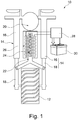
Fig. 1 dargestellte Zweirad 10 weist ein Rad 12 auf, das an zwei Seiten von jeweils einer Dämpfereinheit 14 in der Art einer Radaufhängung gedämpft und gefedert ist. Die Dämpfereinheit 14 weist einen mit dem Chassis 20 des Zweirads 10 verbundenen Dämpferzylinder 16 und ein in dem Dämpferzylinder geführtes und mit dem Rad 12 gekoppeltes Federbein 18 auf. An dem Dämpferzylinder 16 und an dem Federbein 18 greift eine nicht dargestellte Dämpferfeder an. Die Federbeine 18 beider Dämpfereinheiten 14 sind über eine mechanische Koppelung 22 mit einer Magnetanordnung 24 verbunden, die parallel zur Dämpfungsbewegung der Dämpfereinheiten 14 innerhalb einer mit dem Chassis 20 verbundenen Spule 26 verlagert werden kann, um dadurch einen elektrischen Strom in der Spule 26 zu induzieren. Vorzugsweise wird durch die mechanische Koppelung 22 eine Wegübersetzung der Relativbewegung des Federbeins 18 im Dämpferzylinder 16 zur Relativbewegung der Magnetanordnung 24 in der Spule 26 erreicht. Der Strom der Spule 26 kann über eine Leistungselektronik 28, die insbesondere einen Gleichrichter und einen Gleichspannungswandler aufweist, in einer wiederaufladbaren Batterie 30 gespeichert werden. Die Magnetanordnung 24 und die Spule 26 sind zwischen den Dämpfereinheiten 14 oberhalb von dem Rad 12 des Zweirads 10 positioniert, so dass ein Axialbereich des Rads 12 in radialer Richtung des Rads 12 betrachtet die Magnetanordnung 24 und die Spule 26 überdecken kann. - Wie in
Fig. 2 dargestellt weist die Magnetanordnung 24 antiparallel angeordnete Magnete 32 auf, die parallel zu Dämpfungsbewegung der Dämpfereinheiten 14 parallel geschaltet wechselpolig parallel zueinander ausgerichtet sind. Die Magneten 32 sind insbesondere als Flachstabmagneten ausgestaltet, die im Wesentlichen in horizontaler Richtung ausgerichtet sind, wobei in vertikaler Richtung auf dem Nordpol des einen Magneten 32 ein Südpol des nachfolgenden Magneten 32 folgt und immer so weiter. Die Nord-Süd-Ausrichtung der Magneten ist im Wesentlichen parallel zueinander, wobei die Richtung des Magnetfelds nachfolgender Magneten 32 in entgegengesetzte Richtungen weisen. Die Spule 26 weist parallel zu Dämpfungsbewegung der Dämpfereinheiten 14 verlaufende Leiterbereiche auf, die in Umfangsrichtung um die Magnetanordnung 24 herum angeordnet sind, wobei jeweils in Umfangsrichtung nachfolgende Leiterbereiche zwischen den Anschlüssen der Spule 26 miteinander kontaktiert sind. Die Magnetanordnung 24 ist über ein beispielsweise als Öffnung ausgestaltetes erstes Befestigungsmittel 34 mit der Koppelung 22 verbunden. Die Spule 24 kann Teil einer Hülse sein, in der die Magnetanordnung parallel zu Dämpfungsbewegung der Dämpfereinheiten 14, insbesondere verdrehgesichert, linear geführt ist und die über ein beispielsweise als Öffnung ausgestaltetes zweites Befestigungsmittel 36 mit dem Chassis 20 verbunden ist. -
- 10
- Zweirad
- 12
- Rad
- 14
- Dämpfereinheit
- 16
- Dämpferzylinder
- 18
- Federbein
- 20
- Chassis
- 22
- Koppelung
- 24
- Magnetanordnung
- 26
- Spule
- 28
- Leistungselektronik
- 30
- Batterie
- 32
- Magnet
- 34
- erstes Befestigungsmittel
- 36
- zweites Befestigungsmittel
Claims (9)
- Stoßdämpferanordnung für ein Fahrzeug zur gedämpften Abfederung von Stößen, insbesondere für ein Zweirad (10),
mit einem Stoßdämpfer, der einen Dämpferzylinder (16), ein in dem Dämpferzylinder (16) zur Bereitstellung einer Dämpfung linear geführtes Federbein (18), eine Magnetanordnung (24) zur Erzeugung eines magnetischen Felds und eine mit der Magnetanordnung (24) zur elektromagnetischen Induktion zusammenwirkenden Spule (26) aufweist, wobei eine lineare Relativbewegung der Magnetanordnung (24) zur Spule (26) mit einer Relativbewegung des Federbeins (18) zum Dämpferzylinder (16) gekoppelt ist, wobei die Magnetanordnung (24) und die Spule (26) außerhalb des Dämpferzylinders (16) angeordnet sind, und mit einem weiteren Dämpferzylinder und einem in dem weiteren Dämpferzylinder zur Bereitstellung einer Dämpfung linear geführten weiteren Federbein, wobei die Magnetanordnung (24) und die Spule (26) mit dem weiteren Dämpfer und mit dem weiteren Federbein gekoppelt sind, dadurch gekennzeichnet, dass
die Magnetanordnung (24) wechselpolig im Wesentlichen parallel zueinander ausgerichtete Magneten (32) aufweist, und dass die Magnetanordnung (24) und die Spule (26) zwischen dem Dämpferzylinder und dem weiteren Dämpferzylinder angeordnet sind. - Stoßdämpferanordnung nach Anspruch 1 dadurch gekennzeichnet, dass die Nord-Süd-Ausrichtung der Magneten (32) im Wesentlichen senkrecht zur Relativbewegung der Magnetanordnung (24) zur Spule (26) ausgerichtet ist.
- Stoßdämpferanordnung nach Anspruch 1 oder 2 dadurch gekennzeichnet, dass die Magnetanordnung (24) ausschließlich linear verlagerbar ist.
- Stoßdämpferanordnung nach einem der Ansprüche 1 bis 3 dadurch gekennzeichnet, dass die Relativbewegung der Magnetanordnung (24) zur Spule (26) im Wesentlichen parallel und/oder koaxial zur Relativbewegung des Federbeins (18) zum Dämpferzylinder (16) vorgesehen ist.
- Stoßdämpferanordnung nach einem der Ansprüche 1 bis 4 dadurch gekennzeichnet, dass die Magnetanordnung (24) und die Spule (26) zu dem Dämpferzylinder (16) in radialer Richtung versetzt angeordnet sind.
- Stoßdämpferanordnung nach einem der Ansprüche 1 bis 5 dadurch gekennzeichnet, dass die Magneten (32) der Magnetanordnung (24) als Permanentmagnet oder als Elektromagnet ausgestaltet sind.
- Stoßdämpferanordnung nach einem der Ansprüche 1 bis 5 dadurch gekennzeichnet, dass die Spule (26) mit einem Gleichrichter zur Erzeugung von Gleichstrom für eine speicherbare Batterie (30) verbunden ist.
- Stoßdämpferanordnung nach Anspruch 7 dadurch gekennzeichnet, dass zwischen dem Gleichrichter und der Batterie (30) ein Gleichspannungswandler zur Wandlung der den Gleichrichter verlassenden Spannung auf eine Nennbetriebsspannung für die Batterie (30) zwischengeschaltet ist.
- Fahrzeug, insbesondere Zweirad (10), mit einer Stoßdämpferanordnung nach einem der Ansprüche 1 bis 8, wobei die Magnetanordnung (24) und die Spule (26) in einem, von einem Rad (12) des Fahrzeugs überdeckten Axialbereich angeordnet sind.
Applications Claiming Priority (2)
| Application Number | Priority Date | Filing Date | Title |
|---|---|---|---|
| DE102017105869.9A DE102017105869A1 (de) | 2017-03-20 | 2017-03-20 | Stoßdämpfer |
| PCT/DE2018/100036 WO2018171827A1 (de) | 2017-03-20 | 2018-01-17 | STOßDÄMPFER |
Publications (2)
| Publication Number | Publication Date |
|---|---|
| EP3601030A1 EP3601030A1 (de) | 2020-02-05 |
| EP3601030B1 true EP3601030B1 (de) | 2021-01-06 |
Family
ID=61163453
Family Applications (1)
| Application Number | Title | Priority Date | Filing Date |
|---|---|---|---|
| EP18703192.7A Active EP3601030B1 (de) | 2017-03-20 | 2018-01-17 | Stossdämpfer mit energierückgewinnung |
Country Status (4)
| Country | Link |
|---|---|
| EP (1) | EP3601030B1 (de) |
| CN (1) | CN110461699B (de) |
| DE (1) | DE102017105869A1 (de) |
| WO (1) | WO2018171827A1 (de) |
Families Citing this family (3)
| Publication number | Priority date | Publication date | Assignee | Title |
|---|---|---|---|---|
| WO2021191647A1 (en) * | 2020-03-24 | 2021-09-30 | Markus Fleckenstein | Electromechanical shock absorber for energy recovery |
| CN114165547A (zh) * | 2021-11-13 | 2022-03-11 | 辽宁石油化工大学 | 一种复合型磁力调节钻头冲击减震装置及减震方法 |
| IT202200026394A1 (it) * | 2022-12-22 | 2024-06-22 | Paioli S R L | Forcella per veicoli |
Family Cites Families (20)
| Publication number | Priority date | Publication date | Assignee | Title |
|---|---|---|---|---|
| DE8222808U1 (de) * | 1982-08-12 | 1982-12-23 | Siemens AG, 1000 Berlin und 8000 München | Induktive Feder- und Dämpfervorrichtung |
| ES2064251B1 (es) * | 1993-01-04 | 1998-02-16 | Calleja Vidal Carlos | Balanceador articulado con eje oscilante y posibilidad de bloqueo. |
| JPH11343962A (ja) * | 1998-06-01 | 1999-12-14 | Kazuhiro Kawahara | 自動車ショック発電機 |
| DE10147720A1 (de) * | 2001-09-27 | 2003-04-10 | Daimler Chrysler Ag | Autarkes Energiegewinnungssystem |
| JP2004215375A (ja) * | 2002-12-27 | 2004-07-29 | 紘二 ▲吉▼岡 | 発電ダンパ装置 |
| DE10306500A1 (de) * | 2003-02-17 | 2004-08-26 | Bayerische Motoren Werke Ag | Aktive Fahrzeug-Radaufhängung mit einem Linearmotor |
| DE102007054771A1 (de) * | 2007-11-16 | 2009-05-20 | Uwe Schulte-Michels | Elektromechanischer Stoßdämpfer bzw. elektromechanisches Feder-Dämpfer Element (zur Umwandlung kinetischer Energie in elektrische Energie bei jeder Art von Fahrzeugen und Schwingungskörpern) |
| CN100577454C (zh) * | 2008-10-08 | 2010-01-06 | 毕国忠 | 车用减振动能收集器 |
| TW201102501A (en) * | 2009-07-03 | 2011-01-16 | Jing-Dae Huang | Linear-reciprocal waste energy recycling device |
| DE102010036658A1 (de) * | 2010-07-27 | 2012-02-02 | Dr. Ing. H.C. F. Porsche Aktiengesellschaft | Vorrichtung |
| CN202602511U (zh) * | 2012-06-14 | 2012-12-12 | 辽宁工业大学 | 自发电式汽车减震器 |
| CN202652034U (zh) * | 2012-06-25 | 2013-01-02 | 龚格知 | 电动汽车避震发电机 |
| FR2995561B1 (fr) | 2012-09-18 | 2015-06-05 | Soben | Dispositif de suspension a dispositif electromagnetique integre de recuperation d'energie |
| KR101390476B1 (ko) * | 2012-10-09 | 2014-05-02 | 도태환 | 발전기 내장형 쇽업소버 |
| WO2014105703A2 (en) * | 2012-12-26 | 2014-07-03 | Nulman Yanir | Method and apparatus for recovery of parasitic energy losses |
| TW201427849A (zh) * | 2013-01-07 | 2014-07-16 | 廖人立 | 車用發電裝置 |
| US9133900B2 (en) * | 2013-12-16 | 2015-09-15 | GM Global Technology Operations LLC | Method and apparatus for suspension damping including negative stiffness employing a permanent magnet |
| BR112017013112B1 (pt) * | 2014-12-19 | 2022-10-04 | MAGNETI MARELLI S.p.A. | Amortecedor hidráulico regenerativo para suspensão de veículo |
| JP2016140207A (ja) * | 2015-01-29 | 2016-08-04 | 大同特殊鋼株式会社 | 振動式発電装置 |
| CN105711368B (zh) * | 2016-03-07 | 2018-01-30 | 大连理工大学 | 一种基于被动悬架的电磁俘能系统 |
-
2017
- 2017-03-20 DE DE102017105869.9A patent/DE102017105869A1/de not_active Ceased
-
2018
- 2018-01-17 WO PCT/DE2018/100036 patent/WO2018171827A1/de not_active Ceased
- 2018-01-17 CN CN201880018835.6A patent/CN110461699B/zh active Active
- 2018-01-17 EP EP18703192.7A patent/EP3601030B1/de active Active
Non-Patent Citations (1)
| Title |
|---|
| None * |
Also Published As
| Publication number | Publication date |
|---|---|
| CN110461699B (zh) | 2021-12-28 |
| CN110461699A (zh) | 2019-11-15 |
| EP3601030A1 (de) | 2020-02-05 |
| WO2018171827A1 (de) | 2018-09-27 |
| DE102017105869A1 (de) | 2018-09-20 |
Similar Documents
| Publication | Publication Date | Title |
|---|---|---|
| DE102012213265A1 (de) | Elektromagnetisches Aufhängungssystem | |
| EP3601030B1 (de) | Stossdämpfer mit energierückgewinnung | |
| EP2398660B1 (de) | Verfahren und ladevorrichtung zum aufladen einer kraftfahrzeugbatterie | |
| DE102021211992A1 (de) | Rotor für eine fremderregte Synchronmaschine | |
| WO2005057760A1 (de) | Fahrwerkbauteil | |
| DE102015200847A1 (de) | Spuleneinheit für eine Übertragungsanordnung zur induktiven Energieübertragung | |
| DE102010038281A1 (de) | Energierekuperation aus einer Fahrzeugfederung | |
| EP3500449B1 (de) | Energiespeichereinrichtung zur bereitstellung elektrischer energie für eine antriebsvorrichtung eines kraftfahrzeuges und kraftfahrzeug | |
| DE102022104375A1 (de) | Stator, elektrische Axialflussmaschine, Kraftfahrzeug und Verfahren zur Herstellung einer Statorwicklung für einen Stator | |
| EP1584133A1 (de) | Elektrische maschine für den propulsionsantrieb eines u-boots mit einer permanentmagnetisch erregten synchronmaschine | |
| DE102016124184A1 (de) | Rotierende elektrische Maschine mit enthaltener Steuerungsvorrichtung | |
| DE8222808U1 (de) | Induktive Feder- und Dämpfervorrichtung | |
| DE10220846A1 (de) | Fahrzeug, insbesondere motorgetriebenes Strassenfahrzeug | |
| EP3385125B1 (de) | Kraftfahrzeug | |
| WO2018146241A1 (de) | Elektromotor | |
| DE102009037084A1 (de) | Wankstabilisator-Anordnung eines Fahrzeugs mit einer Einrichtung zur Bedämpfung von Wankbewegungen | |
| DE202008008053U1 (de) | Stromerzeuger | |
| DE102021102219A1 (de) | Elektrische Maschine mit in Radialrichtung aus dem Stator herausragenden Befestigungsabschnitten | |
| DE102012201617A1 (de) | Vorrichtung zum transformatorischen Übertragen von elektrischer Energie, elektrisch angetriebenes Kraftfahrzeug sowie entsprechendes Verfahren und Verwendung | |
| DE102017011846A1 (de) | Ladeeinrichtung zum induktiven Laden eines Energiespeichers eines Kraftfahrzeugs,insbesondere eines Kraftwagens | |
| EP3755572B1 (de) | Antriebsstrang mit zwei unterschiedlich spannung abgebenden batterien, elektro-antriebs-system mit niedervoltstäbe umgebende hochvolt-wicklungen, elektromotor mit separatem hochvolt-pulswechselrichter und verfahren zum betreiben eines elektromotors | |
| DE102014212577A1 (de) | Elektrische Maschine | |
| DE4431249C1 (de) | Tilgeranordnung für Drehschwingungen | |
| DE102017103401A1 (de) | Achsantriebseinheit mit induktivem Ladeempfänger, Antriebsachse und Kraftfahrzeug | |
| DE102019000107B4 (de) | Stoßdämpfer zur Erzeugung einer lnduktionsspannung |
Legal Events
| Date | Code | Title | Description |
|---|---|---|---|
| STAA | Information on the status of an ep patent application or granted ep patent |
Free format text: STATUS: UNKNOWN |
|
| STAA | Information on the status of an ep patent application or granted ep patent |
Free format text: STATUS: THE INTERNATIONAL PUBLICATION HAS BEEN MADE |
|
| PUAI | Public reference made under article 153(3) epc to a published international application that has entered the european phase |
Free format text: ORIGINAL CODE: 0009012 |
|
| STAA | Information on the status of an ep patent application or granted ep patent |
Free format text: STATUS: REQUEST FOR EXAMINATION WAS MADE |
|
| 17P | Request for examination filed |
Effective date: 20191021 |
|
| AK | Designated contracting states |
Kind code of ref document: A1 Designated state(s): AL AT BE BG CH CY CZ DE DK EE ES FI FR GB GR HR HU IE IS IT LI LT LU LV MC MK MT NL NO PL PT RO RS SE SI SK SM TR |
|
| AX | Request for extension of the european patent |
Extension state: BA ME |
|
| DAV | Request for validation of the european patent (deleted) | ||
| DAX | Request for extension of the european patent (deleted) | ||
| RIC1 | Information provided on ipc code assigned before grant |
Ipc: B62K 25/08 20060101AFI20200716BHEP Ipc: F03G 7/08 20060101ALI20200716BHEP Ipc: B60G 13/14 20060101ALI20200716BHEP Ipc: H02K 41/03 20060101ALI20200716BHEP Ipc: H02K 35/02 20060101ALI20200716BHEP |
|
| GRAP | Despatch of communication of intention to grant a patent |
Free format text: ORIGINAL CODE: EPIDOSNIGR1 |
|
| STAA | Information on the status of an ep patent application or granted ep patent |
Free format text: STATUS: GRANT OF PATENT IS INTENDED |
|
| INTG | Intention to grant announced |
Effective date: 20200928 |
|
| RIN1 | Information on inventor provided before grant (corrected) |
Inventor name: DOSHI, PRITESH |
|
| GRAS | Grant fee paid |
Free format text: ORIGINAL CODE: EPIDOSNIGR3 |
|
| GRAA | (expected) grant |
Free format text: ORIGINAL CODE: 0009210 |
|
| STAA | Information on the status of an ep patent application or granted ep patent |
Free format text: STATUS: THE PATENT HAS BEEN GRANTED |
|
| AK | Designated contracting states |
Kind code of ref document: B1 Designated state(s): AL AT BE BG CH CY CZ DE DK EE ES FI FR GB GR HR HU IE IS IT LI LT LU LV MC MK MT NL NO PL PT RO RS SE SI SK SM TR |
|
| REG | Reference to a national code |
Ref country code: GB Ref legal event code: FG4D Free format text: NOT ENGLISH |
|
| REG | Reference to a national code |
Ref country code: AT Ref legal event code: REF Ref document number: 1352066 Country of ref document: AT Kind code of ref document: T Effective date: 20210115 Ref country code: CH Ref legal event code: EP |
|
| REG | Reference to a national code |
Ref country code: DE Ref legal event code: R096 Ref document number: 502018003565 Country of ref document: DE |
|
| REG | Reference to a national code |
Ref country code: IE Ref legal event code: FG4D Free format text: LANGUAGE OF EP DOCUMENT: GERMAN |
|
| REG | Reference to a national code |
Ref country code: NL Ref legal event code: MP Effective date: 20210106 |
|
| REG | Reference to a national code |
Ref country code: LT Ref legal event code: MG9D |
|
| PG25 | Lapsed in a contracting state [announced via postgrant information from national office to epo] |
Ref country code: NO Free format text: LAPSE BECAUSE OF FAILURE TO SUBMIT A TRANSLATION OF THE DESCRIPTION OR TO PAY THE FEE WITHIN THE PRESCRIBED TIME-LIMIT Effective date: 20210406 Ref country code: PT Free format text: LAPSE BECAUSE OF FAILURE TO SUBMIT A TRANSLATION OF THE DESCRIPTION OR TO PAY THE FEE WITHIN THE PRESCRIBED TIME-LIMIT Effective date: 20210506 Ref country code: LT Free format text: LAPSE BECAUSE OF FAILURE TO SUBMIT A TRANSLATION OF THE DESCRIPTION OR TO PAY THE FEE WITHIN THE PRESCRIBED TIME-LIMIT Effective date: 20210106 Ref country code: BG Free format text: LAPSE BECAUSE OF FAILURE TO SUBMIT A TRANSLATION OF THE DESCRIPTION OR TO PAY THE FEE WITHIN THE PRESCRIBED TIME-LIMIT Effective date: 20210406 Ref country code: HR Free format text: LAPSE BECAUSE OF FAILURE TO SUBMIT A TRANSLATION OF THE DESCRIPTION OR TO PAY THE FEE WITHIN THE PRESCRIBED TIME-LIMIT Effective date: 20210106 Ref country code: FI Free format text: LAPSE BECAUSE OF FAILURE TO SUBMIT A TRANSLATION OF THE DESCRIPTION OR TO PAY THE FEE WITHIN THE PRESCRIBED TIME-LIMIT Effective date: 20210106 Ref country code: GR Free format text: LAPSE BECAUSE OF FAILURE TO SUBMIT A TRANSLATION OF THE DESCRIPTION OR TO PAY THE FEE WITHIN THE PRESCRIBED TIME-LIMIT Effective date: 20210407 |
|
| PG25 | Lapsed in a contracting state [announced via postgrant information from national office to epo] |
Ref country code: SE Free format text: LAPSE BECAUSE OF FAILURE TO SUBMIT A TRANSLATION OF THE DESCRIPTION OR TO PAY THE FEE WITHIN THE PRESCRIBED TIME-LIMIT Effective date: 20210106 Ref country code: LV Free format text: LAPSE BECAUSE OF FAILURE TO SUBMIT A TRANSLATION OF THE DESCRIPTION OR TO PAY THE FEE WITHIN THE PRESCRIBED TIME-LIMIT Effective date: 20210106 Ref country code: PL Free format text: LAPSE BECAUSE OF FAILURE TO SUBMIT A TRANSLATION OF THE DESCRIPTION OR TO PAY THE FEE WITHIN THE PRESCRIBED TIME-LIMIT Effective date: 20210106 Ref country code: RS Free format text: LAPSE BECAUSE OF FAILURE TO SUBMIT A TRANSLATION OF THE DESCRIPTION OR TO PAY THE FEE WITHIN THE PRESCRIBED TIME-LIMIT Effective date: 20210106 |
|
| REG | Reference to a national code |
Ref country code: CH Ref legal event code: PL |
|
| PG25 | Lapsed in a contracting state [announced via postgrant information from national office to epo] |
Ref country code: LU Free format text: LAPSE BECAUSE OF NON-PAYMENT OF DUE FEES Effective date: 20210117 Ref country code: IS Free format text: LAPSE BECAUSE OF FAILURE TO SUBMIT A TRANSLATION OF THE DESCRIPTION OR TO PAY THE FEE WITHIN THE PRESCRIBED TIME-LIMIT Effective date: 20210506 |
|
| REG | Reference to a national code |
Ref country code: BE Ref legal event code: MM Effective date: 20210131 |
|
| REG | Reference to a national code |
Ref country code: DE Ref legal event code: R097 Ref document number: 502018003565 Country of ref document: DE |
|
| PG25 | Lapsed in a contracting state [announced via postgrant information from national office to epo] |
Ref country code: SM Free format text: LAPSE BECAUSE OF FAILURE TO SUBMIT A TRANSLATION OF THE DESCRIPTION OR TO PAY THE FEE WITHIN THE PRESCRIBED TIME-LIMIT Effective date: 20210106 Ref country code: CZ Free format text: LAPSE BECAUSE OF FAILURE TO SUBMIT A TRANSLATION OF THE DESCRIPTION OR TO PAY THE FEE WITHIN THE PRESCRIBED TIME-LIMIT Effective date: 20210106 Ref country code: EE Free format text: LAPSE BECAUSE OF FAILURE TO SUBMIT A TRANSLATION OF THE DESCRIPTION OR TO PAY THE FEE WITHIN THE PRESCRIBED TIME-LIMIT Effective date: 20210106 Ref country code: MC Free format text: LAPSE BECAUSE OF FAILURE TO SUBMIT A TRANSLATION OF THE DESCRIPTION OR TO PAY THE FEE WITHIN THE PRESCRIBED TIME-LIMIT Effective date: 20210106 |
|
| PLBE | No opposition filed within time limit |
Free format text: ORIGINAL CODE: 0009261 |
|
| STAA | Information on the status of an ep patent application or granted ep patent |
Free format text: STATUS: NO OPPOSITION FILED WITHIN TIME LIMIT |
|
| PG25 | Lapsed in a contracting state [announced via postgrant information from national office to epo] |
Ref country code: RO Free format text: LAPSE BECAUSE OF FAILURE TO SUBMIT A TRANSLATION OF THE DESCRIPTION OR TO PAY THE FEE WITHIN THE PRESCRIBED TIME-LIMIT Effective date: 20210106 Ref country code: SK Free format text: LAPSE BECAUSE OF FAILURE TO SUBMIT A TRANSLATION OF THE DESCRIPTION OR TO PAY THE FEE WITHIN THE PRESCRIBED TIME-LIMIT Effective date: 20210106 Ref country code: CH Free format text: LAPSE BECAUSE OF NON-PAYMENT OF DUE FEES Effective date: 20210131 Ref country code: DK Free format text: LAPSE BECAUSE OF FAILURE TO SUBMIT A TRANSLATION OF THE DESCRIPTION OR TO PAY THE FEE WITHIN THE PRESCRIBED TIME-LIMIT Effective date: 20210106 Ref country code: LI Free format text: LAPSE BECAUSE OF NON-PAYMENT OF DUE FEES Effective date: 20210131 |
|
| 26N | No opposition filed |
Effective date: 20211007 |
|
| PG25 | Lapsed in a contracting state [announced via postgrant information from national office to epo] |
Ref country code: ES Free format text: LAPSE BECAUSE OF FAILURE TO SUBMIT A TRANSLATION OF THE DESCRIPTION OR TO PAY THE FEE WITHIN THE PRESCRIBED TIME-LIMIT Effective date: 20210106 Ref country code: FR Free format text: LAPSE BECAUSE OF NON-PAYMENT OF DUE FEES Effective date: 20210306 Ref country code: AL Free format text: LAPSE BECAUSE OF FAILURE TO SUBMIT A TRANSLATION OF THE DESCRIPTION OR TO PAY THE FEE WITHIN THE PRESCRIBED TIME-LIMIT Effective date: 20210106 Ref country code: IE Free format text: LAPSE BECAUSE OF NON-PAYMENT OF DUE FEES Effective date: 20210117 |
|
| PG25 | Lapsed in a contracting state [announced via postgrant information from national office to epo] |
Ref country code: SI Free format text: LAPSE BECAUSE OF FAILURE TO SUBMIT A TRANSLATION OF THE DESCRIPTION OR TO PAY THE FEE WITHIN THE PRESCRIBED TIME-LIMIT Effective date: 20210106 |
|
| PG25 | Lapsed in a contracting state [announced via postgrant information from national office to epo] |
Ref country code: IS Free format text: LAPSE BECAUSE OF FAILURE TO SUBMIT A TRANSLATION OF THE DESCRIPTION OR TO PAY THE FEE WITHIN THE PRESCRIBED TIME-LIMIT Effective date: 20210506 |
|
| PG25 | Lapsed in a contracting state [announced via postgrant information from national office to epo] |
Ref country code: BE Free format text: LAPSE BECAUSE OF NON-PAYMENT OF DUE FEES Effective date: 20210131 |
|
| GBPC | Gb: european patent ceased through non-payment of renewal fee |
Effective date: 20220117 |
|
| PG25 | Lapsed in a contracting state [announced via postgrant information from national office to epo] |
Ref country code: GB Free format text: LAPSE BECAUSE OF NON-PAYMENT OF DUE FEES Effective date: 20220117 |
|
| P01 | Opt-out of the competence of the unified patent court (upc) registered |
Effective date: 20230522 |
|
| PG25 | Lapsed in a contracting state [announced via postgrant information from national office to epo] |
Ref country code: NL Free format text: LAPSE BECAUSE OF NON-PAYMENT OF DUE FEES Effective date: 20210206 Ref country code: CY Free format text: LAPSE BECAUSE OF FAILURE TO SUBMIT A TRANSLATION OF THE DESCRIPTION OR TO PAY THE FEE WITHIN THE PRESCRIBED TIME-LIMIT Effective date: 20210106 |
|
| PG25 | Lapsed in a contracting state [announced via postgrant information from national office to epo] |
Ref country code: HU Free format text: LAPSE BECAUSE OF FAILURE TO SUBMIT A TRANSLATION OF THE DESCRIPTION OR TO PAY THE FEE WITHIN THE PRESCRIBED TIME-LIMIT; INVALID AB INITIO Effective date: 20180117 |
|
| PG25 | Lapsed in a contracting state [announced via postgrant information from national office to epo] |
Ref country code: MK Free format text: LAPSE BECAUSE OF FAILURE TO SUBMIT A TRANSLATION OF THE DESCRIPTION OR TO PAY THE FEE WITHIN THE PRESCRIBED TIME-LIMIT Effective date: 20210106 |
|
| PG25 | Lapsed in a contracting state [announced via postgrant information from national office to epo] |
Ref country code: TR Free format text: LAPSE BECAUSE OF FAILURE TO SUBMIT A TRANSLATION OF THE DESCRIPTION OR TO PAY THE FEE WITHIN THE PRESCRIBED TIME-LIMIT Effective date: 20210106 |
|
| PG25 | Lapsed in a contracting state [announced via postgrant information from national office to epo] |
Ref country code: MT Free format text: LAPSE BECAUSE OF FAILURE TO SUBMIT A TRANSLATION OF THE DESCRIPTION OR TO PAY THE FEE WITHIN THE PRESCRIBED TIME-LIMIT Effective date: 20210106 |
|
| PGFP | Annual fee paid to national office [announced via postgrant information from national office to epo] |
Ref country code: DE Payment date: 20260131 Year of fee payment: 9 |
|
| PGFP | Annual fee paid to national office [announced via postgrant information from national office to epo] |
Ref country code: AT Payment date: 20260122 Year of fee payment: 9 |
|
| PGFP | Annual fee paid to national office [announced via postgrant information from national office to epo] |
Ref country code: IT Payment date: 20260126 Year of fee payment: 9 |