EP3597151B1 - Herzklappenreparatur und -ersatz - Google Patents
Herzklappenreparatur und -ersatz Download PDFInfo
- Publication number
- EP3597151B1 EP3597151B1 EP19193911.5A EP19193911A EP3597151B1 EP 3597151 B1 EP3597151 B1 EP 3597151B1 EP 19193911 A EP19193911 A EP 19193911A EP 3597151 B1 EP3597151 B1 EP 3597151B1
- Authority
- EP
- European Patent Office
- Prior art keywords
- anchor
- spring
- anchors
- valve
- housing
- Prior art date
- Legal status (The legal status is an assumption and is not a legal conclusion. Google has not performed a legal analysis and makes no representation as to the accuracy of the status listed.)
- Active
Links
Images


Classifications
-
- A—HUMAN NECESSITIES
- A61—MEDICAL OR VETERINARY SCIENCE; HYGIENE
- A61B—DIAGNOSIS; SURGERY; IDENTIFICATION
- A61B17/00—Surgical instruments, devices or methods
- A61B17/04—Surgical instruments, devices or methods for suturing wounds; Holders or packages for needles or suture materials
- A61B17/0487—Suture clamps, clips or locks, e.g. for replacing suture knots; Instruments for applying or removing suture clamps, clips or locks
-
- A—HUMAN NECESSITIES
- A61—MEDICAL OR VETERINARY SCIENCE; HYGIENE
- A61F—FILTERS IMPLANTABLE INTO BLOOD VESSELS; PROSTHESES; DEVICES PROVIDING PATENCY TO, OR PREVENTING COLLAPSING OF, TUBULAR STRUCTURES OF THE BODY, e.g. STENTS; ORTHOPAEDIC, NURSING OR CONTRACEPTIVE DEVICES; FOMENTATION; TREATMENT OR PROTECTION OF EYES OR EARS; BANDAGES, DRESSINGS OR ABSORBENT PADS; FIRST-AID KITS
- A61F2/00—Filters implantable into blood vessels; Prostheses, i.e. artificial substitutes or replacements for parts of the body; Appliances for connecting them with the body; Devices providing patency to, or preventing collapsing of, tubular structures of the body, e.g. stents
- A61F2/02—Prostheses implantable into the body
- A61F2/24—Heart valves ; Vascular valves, e.g. venous valves; Heart implants, e.g. passive devices for improving the function of the native valve or the heart muscle; Transmyocardial revascularisation [TMR] devices; Valves implantable in the body
- A61F2/2442—Annuloplasty rings or inserts for correcting the valve shape; Implants for improving the function of a native heart valve
- A61F2/2445—Annuloplasty rings in direct contact with the valve annulus
-
- A—HUMAN NECESSITIES
- A61—MEDICAL OR VETERINARY SCIENCE; HYGIENE
- A61F—FILTERS IMPLANTABLE INTO BLOOD VESSELS; PROSTHESES; DEVICES PROVIDING PATENCY TO, OR PREVENTING COLLAPSING OF, TUBULAR STRUCTURES OF THE BODY, e.g. STENTS; ORTHOPAEDIC, NURSING OR CONTRACEPTIVE DEVICES; FOMENTATION; TREATMENT OR PROTECTION OF EYES OR EARS; BANDAGES, DRESSINGS OR ABSORBENT PADS; FIRST-AID KITS
- A61F2/00—Filters implantable into blood vessels; Prostheses, i.e. artificial substitutes or replacements for parts of the body; Appliances for connecting them with the body; Devices providing patency to, or preventing collapsing of, tubular structures of the body, e.g. stents
- A61F2/02—Prostheses implantable into the body
- A61F2/24—Heart valves ; Vascular valves, e.g. venous valves; Heart implants, e.g. passive devices for improving the function of the native valve or the heart muscle; Transmyocardial revascularisation [TMR] devices; Valves implantable in the body
- A61F2/2442—Annuloplasty rings or inserts for correcting the valve shape; Implants for improving the function of a native heart valve
- A61F2/2466—Delivery devices therefor
-
- A—HUMAN NECESSITIES
- A61—MEDICAL OR VETERINARY SCIENCE; HYGIENE
- A61B—DIAGNOSIS; SURGERY; IDENTIFICATION
- A61B17/00—Surgical instruments, devices or methods
- A61B17/068—Surgical staplers, e.g. containing multiple staples or clamps
-
- A—HUMAN NECESSITIES
- A61—MEDICAL OR VETERINARY SCIENCE; HYGIENE
- A61B—DIAGNOSIS; SURGERY; IDENTIFICATION
- A61B17/00—Surgical instruments, devices or methods
- A61B2017/00831—Material properties
- A61B2017/00867—Material properties shape memory effect
-
- A—HUMAN NECESSITIES
- A61—MEDICAL OR VETERINARY SCIENCE; HYGIENE
- A61B—DIAGNOSIS; SURGERY; IDENTIFICATION
- A61B17/00—Surgical instruments, devices or methods
- A61B17/04—Surgical instruments, devices or methods for suturing wounds; Holders or packages for needles or suture materials
- A61B17/0401—Suture anchors, buttons or pledgets, i.e. means for attaching sutures to bone, cartilage or soft tissue; Instruments for applying or removing suture anchors
- A61B2017/0409—Instruments for applying suture anchors
-
- A—HUMAN NECESSITIES
- A61—MEDICAL OR VETERINARY SCIENCE; HYGIENE
- A61B—DIAGNOSIS; SURGERY; IDENTIFICATION
- A61B17/00—Surgical instruments, devices or methods
- A61B17/04—Surgical instruments, devices or methods for suturing wounds; Holders or packages for needles or suture materials
- A61B17/0401—Suture anchors, buttons or pledgets, i.e. means for attaching sutures to bone, cartilage or soft tissue; Instruments for applying or removing suture anchors
- A61B2017/0414—Suture anchors, buttons or pledgets, i.e. means for attaching sutures to bone, cartilage or soft tissue; Instruments for applying or removing suture anchors having a suture-receiving opening, e.g. lateral opening
-
- A—HUMAN NECESSITIES
- A61—MEDICAL OR VETERINARY SCIENCE; HYGIENE
- A61B—DIAGNOSIS; SURGERY; IDENTIFICATION
- A61B17/00—Surgical instruments, devices or methods
- A61B17/04—Surgical instruments, devices or methods for suturing wounds; Holders or packages for needles or suture materials
- A61B17/0401—Suture anchors, buttons or pledgets, i.e. means for attaching sutures to bone, cartilage or soft tissue; Instruments for applying or removing suture anchors
- A61B2017/0427—Suture anchors, buttons or pledgets, i.e. means for attaching sutures to bone, cartilage or soft tissue; Instruments for applying or removing suture anchors having anchoring barbs or pins extending outwardly from the anchor body
- A61B2017/0437—Suture anchors, buttons or pledgets, i.e. means for attaching sutures to bone, cartilage or soft tissue; Instruments for applying or removing suture anchors having anchoring barbs or pins extending outwardly from the anchor body the barbs being resilient or spring-like
-
- A—HUMAN NECESSITIES
- A61—MEDICAL OR VETERINARY SCIENCE; HYGIENE
- A61B—DIAGNOSIS; SURGERY; IDENTIFICATION
- A61B17/00—Surgical instruments, devices or methods
- A61B17/04—Surgical instruments, devices or methods for suturing wounds; Holders or packages for needles or suture materials
- A61B17/0401—Suture anchors, buttons or pledgets, i.e. means for attaching sutures to bone, cartilage or soft tissue; Instruments for applying or removing suture anchors
- A61B2017/0464—Suture anchors, buttons or pledgets, i.e. means for attaching sutures to bone, cartilage or soft tissue; Instruments for applying or removing suture anchors for soft tissue
-
- A—HUMAN NECESSITIES
- A61—MEDICAL OR VETERINARY SCIENCE; HYGIENE
- A61B—DIAGNOSIS; SURGERY; IDENTIFICATION
- A61B17/00—Surgical instruments, devices or methods
- A61B17/064—Surgical staples, i.e. penetrating the tissue
- A61B2017/0647—Surgical staples, i.e. penetrating the tissue having one single leg, e.g. tacks
-
- A—HUMAN NECESSITIES
- A61—MEDICAL OR VETERINARY SCIENCE; HYGIENE
- A61F—FILTERS IMPLANTABLE INTO BLOOD VESSELS; PROSTHESES; DEVICES PROVIDING PATENCY TO, OR PREVENTING COLLAPSING OF, TUBULAR STRUCTURES OF THE BODY, e.g. STENTS; ORTHOPAEDIC, NURSING OR CONTRACEPTIVE DEVICES; FOMENTATION; TREATMENT OR PROTECTION OF EYES OR EARS; BANDAGES, DRESSINGS OR ABSORBENT PADS; FIRST-AID KITS
- A61F2220/00—Fixations or connections for prostheses classified in groups A61F2/00 - A61F2/26 or A61F2/82 or A61F9/00 or A61F11/00 or subgroups thereof
- A61F2220/0008—Fixation appliances for connecting prostheses to the body
- A61F2220/0016—Fixation appliances for connecting prostheses to the body with sharp anchoring protrusions, e.g. barbs, pins, spikes
Definitions
- the mitral valve is positioned in the heart left side, between the left atrium and the left ventricle.
- the most typical disease of the mitral valve is insufficiency or regurgitation which occurs when the valve leaflets do not coapt properly.
- Mitra! valve repair by suturing a ring to reduce the annulus diameter is the procedure of choice to correct mitral regurgitation. With the use of current surgical techniques, most regurgitant mitral valves can be repaired or replaced with artificial valve prosthesis.
- mitral valve repair required an extremely invasive surgical approach that includes a sternotomy, cardio-pulmonary bypass, cardiac arrest, and an incision in the heart itself to expose the mitral valve. Such procedure is associated with high morbidity and mortality.
- a percutaneous device that can effectively treat the disease without the need for open heart surgery could greatly improve patient benefit and may include other patients that previously could not be treated with surgery being too old or frail for such invasive procedure.
- Surgical annuloplasty is a technique aimed to reduce the size of the fibrous tissue at the base of the mitral valve, called the annulus.
- the annulus becomes enlarged, enabling blood to back flow up into the left atrium, through the gap between the two separated valve leaflets.
- the repair is done with sutures to make the opening smaller, helping the two leaflets meet and co-apt again when the valve closes.
- Surgical valvuloplasty is a technique aimed to ensure proper closure of the valve leaflets.
- Leaflet function can be impaired as the result of prolapse of a leaflet due to ruptured chordae.
- the leaflet reconstruction is done by leaflet resection and reshaped with sutures. In most cases both annuloplasty and valvuloplasty is needed in order to regain optimal mitral valve function.
- mitral valve surgery Due to the invasive nature of the mitral valve surgery, and the high risks involved in the procedure, many heart failure patients are poor surgical candidates. Thus, less invasive methods and devices to reduce mitral valve regurgitation would make this therapy available to many more patients.
- US2004/102839 , US2004/1022840 , US6656221 , US6718985 , US6723038 , and US2004/073302 describe minimal invasive approaches to mitral valve annuloplasty, using percutaneous insertion of device into the left ventricle or into the coronary sinus, in order to decrease the annulus size.
- US6626930 and US6575971 disclose a device and method of fastening two pieces of the valve leaflets together, improving competence of the valve.
- US2007/016286 discloses a transluminal collapsible heart valve designed to attach to the native annulus of the native regurgitating mitral valve and replace all in a single step.
- US2012/010700 provides a method for implanting a prosthetic valve apparatus that includes a one way valve and an expandable valve seating. The apparatus is anchored and secured in a newly created orifice near or at the center of the anterior valve leaflet.
- aortic valve the valve positioned between the left ventricle and aorta
- an artificial collapsed valve is delivered through the arteries and positioned inside the diseased native valve, and then expanded to replace it.
- this valve annulus is much bigger and amorphously shaped, and there are no lumen walls or calcific leaflets that may function as retaining surfaces like in the aortic valve, make it very difficult to prevent dislodgment of a valve expanded into place in the mitral position.
- Devices that are attached to the mitral annulus and then collapsed to reduce its diameter need to be secured very tightly and accurately to the tissue in order to withhold the high forces that are required to reduce the annulus diameter.
- WO2013/088327 is prior art under Article 54(3) EPC.
- the present application discloses an invention that builds on the disclosure of WO2013/088327 and provides a number of improvements thereon.
- United States Patent Application US 2005/0070924 A1 discloses a surgical connection apparatus comprising a support structure, a plurality of clips, which can be self-closing clips, each clip being releasably coupled to the support structure, and a plurality of barbs, each barb being coupled to the support structure, the barbs being separate from the clips, which are ejectable from the support structure independently of the barbs.
- the present invention relates to apparatuses for helping repair or replace biological valves and is particularly suited for cardiac valves, such as the mitral and tricuspid valves.
- the invention is directed to an apparatus for triggering a plurality of anchor launchers according to claim 1.
- the housing is cylindrical, the channels are distributed within the cylindrical housing, and the tabs extend outside a circumference of the cylindrical housing.
- the apparatus further includes a rotatable cap, wherein an interior surface of the cap defines a cylindrical void configured to surround the cylindrical housing, and the interior surface has a single protrusion configured to sequentially push each of the tabs from the first position to the second position when the cap is rotated.
- the apparatus further includes a rotatable cap, wherein an interior surface of the cap defines a cylindrical void configured to surround the cylindrical housing, and the interior surface has a plurality of protrusions configured to simultaneously push a plurality of the tabs from the first position to the second position when the cap is rotated.
- the proximal end of the pull wire is affixed directly to the spring or the tab.
- a heart valve repair device comprising an implant and delivery system is delivered into the heart in four sequential stages: In the first stage the implant and support scaffold are advanced in a collapsed configuration inside a capsule through the vascular system to the valve annulus (preferably the Mitral annulus but can be also the Tricuspid annulus).
- the valve annulus preferably the Mitral annulus but can be also the Tricuspid annulus.
- a support scaffold is pushed outside of the capsule and the implant which is attached to the scaffold is spread into a round or D shape circumferential ring onto the valve annulus in 3 optional ways: 1) On the inflow side of the valve with attachment anchors pointing from the atrium side to the ventricle side; 2) On the inflow side of the valve with attachment anchors pointing from the ventricle side to the atrium side; and 3) On the outflow side of the valve with attachment anchors pointing from the ventricle side to the atrium side.
- the anchors are launched into the tissue at once or in a sequential manner and affix the implant to the tissue. The same action also separates the implant from the support scaffold and delivery system.
- the scaffold is retracted and collapsed back into the delivery capsule and the delivery system is withdrawn out of the body.
- the spread implant conforms at least partially to the valve annulus shape, and in some designs the spread implant does not conform at all to the valve annulus shape, but is just affixed to the valve leaflets and is retained there for a few minutes until a valve prosthesis is deployed into it as will be described later on.
- valve insufficiency After the implant is attached to the valve tissue it is possible to treat the valve insufficiency in 5 optional ways: 1) By direct annuloplasty which impose cinching of the implant attached to the valve annulus, hence reducing the annulus diameter and improving valve leaflets coaptation; 2) By restricting annulus dilatation over time due to the constant perimeter of the implant which is attached to the valve annulus and gets embedded into the tissue over time through tissue growth; 3) By facilitating a support ring for valve prosthesis to be implanted at a later procedure after the implant which is attached to the valve annulus gets embedded into the tissue over time through tissue growth; 4) By performing annuloplasty at a later stage in a different procedure weeks or months later after the implant which is attached to the valve annulus gets embedded into the tissue over time through tissue growth; and 5) By facilitating a support ring for valve prosthesis that can be implanted into the ring during the same procedure right after the ring is attached to the valve leaflets.
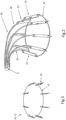
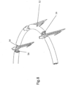
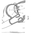
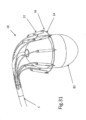
- FIG. 1 shows a design of a mitral valve adjustment/repair implant 10, implanted onto a bio-valve, exemplified by mitral valve M of the heart.
- Implant 10 comprises: a tissue engaging member 12, comprising a loop 14 of wire and a plurality of tissue anchors 16 associated with the loop and having an elongated slot 17 ( FIG. 5 ); a scaffold or implant positioning device 18, in this design comprising plurality of support arms 20; and an anchor launching mechanism 22 ( FIGS 2-7 ).
- Implant 10 is typically positioned in proximity of the mitral valve M via a delivery catheter C.
- the loop 14 of wire is preferably made of metal wire, but in alternative designs the wire may be a non-metallic material. Note that as used herein, "wire" includes metal and/or non-metallic materials. In alternative designs the loop of wire may be replaced by a different loop of material such as a tube, strip, chain, braid, etc. Optionally, a wire may be disposed within the different loop of material.
- FIG. 2 shows an enlarged view of the device in FIG. 1 illustrating anchor launching mechanism 22 in a ready for deployment (launching) and deployed state, respectively; Elongated slot 17 of anchors 16 allow loop 14 to be retained by (operably attached to) the anchors - which will be explained further herein below.
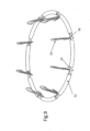
- FIG. 3 shows a design of implant 10 in its configuration when implanted, as will be discussed further below.
- FIGS. 4-6 show details of anchor launching mechanism 22, which comprises a housing 24, typically cylindrical; an anchor launching biasing mechanism, such as coil spring 26 disposed within the housing; and a spring actuator wire 28, having a bent distal end 29, passing through elongated slot 17 and protruding through an opening 30 of housing 24. Bent distal end 29 maintains spring 26 is a compressed configuration.
- Actuator wire 28 passes longitudinally/coaxially through coil spring 26.
- Implant support arms 20 are respectively attached to housings 24, for example by welding. It should be noted that actuator wire 28 can be made of any appropriate material and is not limited to metal.
- Housing 24 has an open end 32 and a spring retention end 34, which in some designs comprises a crimped portion 36 or other such spring retention mechanism, to provide a launching base for spring 26.
- spring has a hooked proximal end 38 adapted to hook at retention end 34 of the housing.
- loop 14 is threaded through each elongated slot 17 of tissue anchors 16.
- housing 24 has a pair of elongated recesses 40 at open end 32 whereby loop 14 can pass.
- FIGS. 4 and 5 show anchors 16 in a pre-launch state where spring 26 is compressed
- FIG. 6 shows the anchors in a launched state with the spring in its normally expanded configuration.
- tissue anchors 16 are typically spaced apart all along loop 14 and loop 14 is threaded through elongated slot 17, allowing the tissue anchor to move (be launched), typically more or less perpendicular (although in some designs at an angle) with respect to the loop.
- loop 14 can be made of any appropriate material and is not limited to metal. Note that while eight anchors are depicted in all the illustrated' designs, the number of anchors can be varied. Preferably at least six anchors are used.
- each anchor 16 has a proximal portion 42 including a spring interfacing portion exemplified by a pair of flat shoulders 44.
- Anchors 16 also have a pointy front end 46, typically with one or more barbs 48. After an anchor is implanted in the forward direction, the barbs 48 resist extraction of the anchor 16 in a backwards direction.
- elongated slot 17 has a relatively large or bulbous open portion or eyelet 50 adjacent proximal portion 42, which can be useful to provide additional space for bent distal end 29 to pass through the elongated slot along with loop 14.
- FIGS. 8-10 shows a modification of the implant wherein loop 14 has a plurality of tissue growth-promotion tubes 52 coaxially surrounding the loop 14 between anchor positions.
- tissue growth-promotion tubes 52 have respective tissue growth inhibiting liners or surfaces 54 ( FIG. 10 ).
- Tissue growth-promotion tubes 52 are made of a material and/or substance adapted to promote and facilitate the growth of tissue thereon, for example an appropriate fabric or coating. If indeed in the form of liners, tissue growth inhibiting liners 54 are disposed tissue growth-promotion tubes 52, e.g. coaxially, and include tissue growth inhibiting material/substance.
- FIGS. 9 and 10 additionally show another design wherein there are two loops, the aforementioned loop 14 and a relatively sturdy auxiliary loop 56 to provide additional robustness to the implant if so desired.
- FIG. 10 shows a modification wherein auxiliary loop further includes a proximal portion 58 that can be used to position the implant 10, in addition to or in place of the above mentioned implant positioning device 18.
- implant 10 is deployed to a position adjacent the bio-valve (e.g. Mitral valve M) via/through delivery catheter C (see FIGS. 11 and 12 ; and also FIGS. 1 and 2 ).
- implant 10 is appropriately located, using support arms 20 and ⁇ or auxiliary loop 56 with its proximal portion 58, actuator wire 28 of each anchor launching mechanism 22 is retracted thereby withdrawing their bent distal ends 29 from respective openings 30 of housings 24.
- springs 26 are released from their compressed state to their expanded state thereby launching tissue anchors 16 into the bio-valve tissue.
- pointy end 46 of each anchor 16 enters the tissue, and barbs 48 help to prevent inadvertent detachment of the anchors.
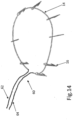
- FIG. 13 illustrates implant 10 connected to the tissue of mitral valve M of the heart after the launching of tissue anchors 16 into the tissue.
- Implant 10 is positioned on the top of the mitral valve M, as a result of being inserted into the heart in a manner such as shown in FIG. 1 , and anchors 16 face generally downward.
- tissue growth start to occur all around the parts of implant 10 that are within the tissue notably the anchors, and later on tissue growth will cover also parts of the implant at close proximity to the tissue surface.
- tissue growth fills the anchors slot 17 they become mechanically locked within the tissue, and over time the entire implant 10 will get embedded in the valve annulus tissue. Since the implant is largely comprised of loop 14 which is made of non-elastic substance, further annulus dilatation over time due to progression of the valve regurgitation disease is prevented.
- the implant further comprises a cinching mechanism 60, for example wherein loop 14 is not in a closed loop configuration rather has generally adjacent free ends 62 and 64.
- the ring-like portion of loop 14 passes through elongated slots 17 of anchors 16 (and in suitable designs, through tissue growth-promotion tubes 52), as before.
- the implant may be cinched via pulling on one or both of the free ends 62 and/or 64 to reduce the diameter of tissue engaging member 12, (however, in some implementations of the operation, cinching action is not required, and could be excluded from procedure).
- Free ends 62 and 64 may extend outside the patient's body or remain under the skin at the upper portion of the chest, much like pace maker leads.
- the tissue growth causes implant 10 to be embedded and integrated to the valve annulus.
- tissue growth within elongated slot 17 helps secure anchors 16 and prevents the implant from being dislodged from the valve annulus.
- FIG. 14 further illustrates a D-shaped loop 14, in contrast to the circular or oval shaped loops illustrated in the aforementioned figures.
- D-shaped loop 14 is particularly suited for use with a human mitral heart valve.
- loop 14 can be configured by choice or design to appropriately correspond to the particular bio-valve for which repair is required.
- FIG. 15 shows another design wherein instead of anchors 16 engaging loop 14 via elongated slot 17, the anchors pass thru a coaxial tube 66 coaxially surrounding the loop - the tube could be, for example a tissue growth promotion tube such as tissue growth-promotion tubes 52. Retention of anchors 16 with coaxial tube 66 is aided by a retention hook 68 at the proximal end of the anchors.
- FIGS. 16 and 17 depict a design where anchor 16 has a cylindrical shape, similar to housing 24 and no such housing is required.
- spring 26 is held in compression between end 34 of cylindrical anchor 16 and a spring launching base, exemplified by a launching base ring 70, attached to implant support arms 20.
- End 34 now provides the function of the aforementioned flat shoulders 44; and launching base ring provides the function of the aforementioned crimped portion 36.
- actuator wire 28 is retracted, its bent distal end 29 (here, illustrated in the form of a half-loop) is retracted from opening 30 thereby releasing cylindrical anchor 16 so that spring 26 expands to launch the anchor.
- FIGS. 18 and 19 shows implant positioning device 18 configured, mutatis mutandis, wherein anchor launching mechanism 22 is adapted to launch anchors 16 into the tissue in a generally upward direction (i.e. from the ventricle side to the atrium side).
- anchor launching mechanism 22 is adapted to launch anchors 16 into the tissue in a generally upward direction (i.e. from the ventricle side to the atrium side).
- This design is particularly useful in the case where the tissue engaging member 12 serves as a support to prevent dislodgement of a valve prosthesis that can be expanded into it right after the tissue engaging member 12 has been deployed.
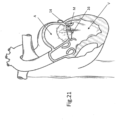
- FIGS. 20-24 illustrate designs adapted for situations where launching anchors 16 upwardly may also be used in cases where access to the insufficient valve is from below, for example via the Apex (see FIG. 20 ), is preferable rather than from above.
- FIGS. 20 and 22 show loop 14 disposed under the Mitral valve leaflets and
- FIG. 21 shows loop 14 disposed onto the Mitral valve leaflets M as the anchors 16 penetrates through the leaflets pointing from the ventricle side to the atrium side.
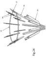
- FIGS. 23 and 24 show the pre-launch and launch situations for upward launching of anchors 16.
- FIG. 23 further illustrates that catheter C can be used to help orient the angle of housings 24, and thus the launch angle of anchors 16. If the distance between catheter C and loop 14 is relatively small, anchors 16 tends to be positioned and launched at a greater angle (relative to being launched perpendicular to loop 14, as was shown in FIGS. 2 and 3 , for example). Adjustment of the launch angle, i.e. pivoting of anchors angle, is made possible by the shape of the support arms 20 to which the housing 24 is attached.
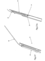
- FIG. 24 also illustrates another modification wherein anchors 16 comprise multiple barbs 48 and wherein elongated slot 17 extends about half-way within the length of the anchors, as seen in FIG. 7A .
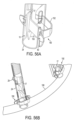
- FIGS. 25-27 and 27A illustrate particular designs wherein anchor launching mechanism 22 is adapted to be used with tissue anchors 16 that are launched in a generally upward direction; and can be actuated by a direct pull, or by a mechanism removed from the valve area.
- Anchor launching mechanism 22 comprises actuation wire 28 and housing 24, however the mechanism does not include spring 26 disposed in the housing. Regardless, for rapid actuation purposes (anchor launch), anchor launch mechanism 22 may further include an external launch actuator device, typically including a spring (not shown), for example, at the proximal end of catheter C, to pull on actuation wire 28.
- an external launch actuator device typically including a spring (not shown), for example, at the proximal end of catheter C, to pull on actuation wire 28.
- anchor 16 may be modified to further comprise an actuation wire eyelet 72 where-through actuation wire 28.
- Distal end 29 of actuation wire 28 is threaded through eyelet 72 and typically has a hook-like configuration while disposed within housing 24 ( FIGS. 25 and 27 ).
- housing 24 need not include an opening such as opening 30, nor does not need a crimped portion 36 or other such spring retention mechanism, as there is no spring in the housing.
- FIGS. 27 and 27A illustrates a modification wherein instead of eyelet 72; each anchor 16 has an actuator-wire distal-end receiving portion such as recess 74, which operates to launch anchors 16 in the same fashion as noted above.
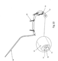
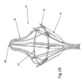
- FIGS. 28-30 show designs, wherein implant 10 further comprises a loop-arrangement/anchor-orientation mechanism 76 useful for arranging the position and/or shape of loop 14 and/or for orienting the angle of housings 24, and thereby orienting the launch angle of tissue anchors 16.
- Anchor orientation mechanism 76 includes a plurality of curved arrangement leads 78 respectively attached to at least some of housings 24, for example by welding. Leads 78 may be an extension of implant support arms 20 and may be arranged to cross at a singular intersection point 80. Leads 78 are attached (e.g. by welding) to housing 24. Thus, leads 78 of orientate mechanism 76 are movable to arrange loop 14 in a desired location and depending on the shape of the leads, the angle of housings 24, and thus anchors 16, can be determined.
- leads 78 can be attached "ad hoc" prior to insertion into a patient, whereby, depending on the attachment location, arrangement leads 78 also be used to orient anchors 16 i.e. control the angle at which the anchors enter the tissue (i.e. changing the length or shape of one or more leads 78 will thus change the angle of the anchors, e.g. shortening the that length will cause the anchors to point outward, whereas increasing that length will bring intersection point 80 farther from loop 14 and thus angle the anchors more parallel to each other (less outward).
- leads 78 will not be welded to housings 24, rather there will be included an "ad hoc" connection or fastening arrangement (not shown), whereby the leads and housings are connected at more than one location along the leads.
- Arrangement/orientation mechanism 76 can be useful for arranging the shape of loop 14 as well as positioning the loop and orienting the anchor angle.
- loop-arrangement/anchor-orientation mechanism 76 either has a predetermined shape, such as a nipple shape ( FIGS. 29 and 30 ) or is adapted to allow its shape to be changed; i.e. leads 78 can be bent.
- FIGS. 31-34 show designs wherein loop arrangement and/or implant positioning device 18 comprises an inflatable balloon 82.
- the figures show exemplary balloons 82 useful for a) making sure support arms 20 are fully expanded before deploying implant 10, b) make sure that loop 14 is concentric with the valve annulus prior to implantation, and c) facilitating an interference step or backing against which to press to be used for pressing implant positioning device 18 and implant 10 onto the valve annulus before implantation as illustrated in figure 34 .
- FIG. 31 illustrates an oval balloon 82;
- FIGS. 32-34 illustrate a droplet-shaped or bulbous balloon 82.
- the balloon can be used to secure the implant positioning device 18 and implant 10 in place during launching of anchors 16.
- FIGS. 32 and 33 also illustrate that balloon 82 can be positioned proximally or distally with respect to loop 14 and implant positioning device 18. Since the balloon can be positioned inside the ventricle and be inflated to a diameter bigger than the diameter of biological valve annulus, it can serve as a backing against which to press positioning device 18 and implant 10 onto the valve annulus before implantation. This will ensure good contact between each of the anchor launching mechanisms 22 and the valve annulus and will create optimal penetration conditions of anchor 16 into the tissue upon launching. Furthermore, the launch angle of anchors 16 (i.e. insertion into the tissue) can be controlled by inflating/deflating balloon 82, with consideration to the size of the biological valve.
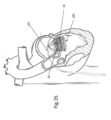
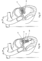
- FIGS. 35-37 illustrate how a device 100 (e.g., a replacement valve) can be fixed to a native valve annulus or leaflets like the mitral valve M or tricuspid valve.
- implant 10 is first implanted and secured with anchors 16 that penetrate the valve leaflets pointing from the ventricle V side toward the atrium A side (hereinafter upwards) as in FIG. 21 and/or FIG. 22 . Then, when device 100 is expanded into implant 10, the friction between anchors 16 and the device 100 secures device 100 in place. Since anchors 16 are directed generally upward, the high pressure in ventricle V helps to further enhance the anchoring of implant 10 to the valve leaflets.
- Device 100 in the illustrating figures represents any suitable commercial expandable heart valve prosthesis that can be tracked in a collapsed configuration through the vascular system and delivered to the heart. It can be a self-expanding prosthesis or a balloon expanding prosthesis or any other type of expanding heart valve prosthesis.
- FIG. 35 further illustrates an exemplary delivery system 101 that can deliver device 100 to the heart.
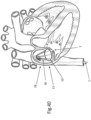
- FIGS. 36 and 37 illustrate how implant 10 can be associated with device 100 for fixing the device to a mitral valve M (or tricuspid valve) leaflets.
- implant 10 and device 100 are implanted via the heart's apex P, preferably, in a minimally invasive surgery as illustrated in FIG.20 .
- implant 10 is first located at the proper location with respect to the bio-valve (mitral in this case) and then secured with anchors 16 facing upward, in accordance with any appropriate design as described herein.
- device 100 is advanced, as shown in FIG. 36 . Through a delivery catheter (not shown), and expanded into implant 10 as seen in FIG. 37 .
- each anchor 16 has a relatively shorter slot 17, typically extending only about half-way along the longitudinal dimension of each anchor, from about half-way along the anchor to relatively close to the anchors' pointy front end 46, as seen in FIG. 7A .
- the contact and sliding motion between the device and anchor 16 changes the angle of the anchors from typically approximately 45 degrees ( FIG. 38 ), although, depending on the angle of support arms 20, to an angle wherein the anchors are more parallel to each other, typically substantially parallel.
- the movement of anchors 16 is illustrated by are A-B in FIG. 38 .
- anchors 16 pivots at the end of slot 17, as in FIG. 7A which is generally at mid-point 84 of the anchors. This angle change provides increased friction between anchors 16 and device 100 thereby securing the device in place.
- device 100 is expanded in the bio-valve until the device presses on a non-slotted portion 86 of anchors 16. As a result of pressing on non-slotted portion 86, that portion is forced outward, and thus the tip of the anchors 46 is moved inward, as the anchors pivot around loop 14. Since anchor tips 46 are locked within the tissue of the valve leaflet, the inward motion of the tips pulls the leaflets closer to device 100 and presses the leaflets against the device, thereby enhancing the sealing and prevent blood flow between the native valve leaflet and the device. It should be understood that device 100 is appropriately sized for the above-described positioning.
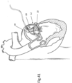
- FIG. 40 illustrates deployment of implant 10 in the tricuspid heart valve T and it should be understood that all the features and functions of the implant and delivery system as illustrated in FIGS. 1 to 39 are applicable to the tricuspid valve.
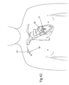
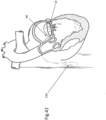
- FIG. 41 illustrates deployment of implant 10 through the left atrium wall rather than tracking in through the vascular system, or deploying the implant through the apex of the heart. Again, it should be understood that all the features and functions of the implant and delivery system illustrated in FIGS. 1 to 39 are applicable to deployment through the atrium wall.
- FIG. 42 illustrates manual cinching of the device in a later procedure after tissue healing has occurred as described above with reference to FIG. 14 .
- FIG. 43 illustrates cinching of the device in a later procedure after tissue healing has occurred as described above with reference to FIG. 14 .
- the mechanical actuator 110 can be actuated and operated magnetically, electrically or by any other appropriate mechanism from outside of the body.
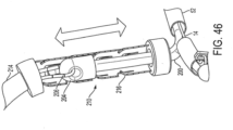
- FIGS. 44-47 depict one exemplary design for implementing cinching.
- the implant has a tissue engaging member 12 that includes a loop of wire 14 and a plurality of tissue growth-promotion tubes 52 coaxially arranged about the loop of wire.
- the tissue growth-promotion tubes 52 are made of a material that promotes ingrowth of tissue, such as a fabric segments, optionally coated with a tissue growth promoting substance. Taken together, the loop of wire 14 and the plurality of tissue growth-promotion tubes 52 collectively form a loop of material.
- the tissue engaging member 12 also includes a plurality of tissue anchors 16 that are arranged with respect to the loop of wire.
- the anchors 16 are spaced apart all along the loop of wire 14 and the loop of wire is threaded through slots in the anchors 16.
- the anchors may be attached to the wire using linking members like those shown in FIGS. 56A and 56B .
- the anchors 16 may be launched using any of the approaches described herein.
- This design also includes a cinching cable 200, which is preferably covered with a slippery coating such as PTFE or the like. Cinching cable 200 has two ends that are threaded through a cinching collar 202 and are attached to a cinching member 204 that has a cinching aperture or eyelet. A cinching lead 206 is threaded through cinching aperture and the lead's free ends may extend outside the patient's body or remain under the skin at the upper portion of the chest, much like pace maker leads.
- a cinching cable 200 which is preferably covered with a slippery coating such as PTFE or the like. Cinching cable 200 has two ends that are threaded through a cinching collar 202 and are attached to a cinching member 204 that has a cinching aperture or eyelet.
- a cinching lead 206 is threaded through cinching aperture and the lead's free ends may extend outside the patient's body or remain under the skin at the upper portion of
- the implant may be cinched by pulling on one or both of the free ends of cinching lead 206 to thereby pull on cinching cable 200 and reduce the diameter of tissue engaging member 12.
- a cinching sleeve 208 is pushed along over the cinching lead 206 until the distal end of the cinching sleeve 208 bottoms out at the cinching collar 202. Then, a cinching tube 210 is pushed through cinching sleeve 208 by a pushing member 214 until the cinching tube 210 reaches cinching collar 202, as seen in FIG. 45 . After this, by pulling on both ends of the cinching lead 206, cinching eyelet member 204 is retracted into cinching tube 210, as seen in FIGS. 46 .
- cinching tube 210 has a plurality of one way flaps or steps 216 spaced apart along the length of the tube for holding cinching member 204 in place as the cinching member 204 retracts in the cinching tube 210, thereby controlling the ultimate length/diameter of cinching cable 200 so as to constrict the annulus of the bio-valve.
- flaps or steps 216 spaced apart along the length of the tube for holding cinching member 204 in place as the cinching member 204 retracts in the cinching tube 210, thereby controlling the ultimate length/diameter of cinching cable 200 so as to constrict the annulus of the bio-valve.
- one end of cinching lead 206 may be pulled to remove the cinching lead, the pushing member 214 may be removed, and the cinching sleeve 208 may also be removed.
- the resultant implant would then appear as is seen in FIG. 47 .
- some or all of these components 206, 208, 214 may remain behind as part of the implant e.g., for implementing additional cinching at a later point in time.
- FIGS. 48A and 48B depict an alternative cinching mechanism in which the ends of the cinching cable 200 are pulled by rotating a spindle 232 in a mechanism 230 that is preferably implanted in the patient's body.
- the rotation may be implemented by a motor that is powered by a battery (not shown) and controlled remotely from outside the patient's body.
- the loop 201 is biased against a spring element 235.
- the spring element 235 When the spring element 235 is initially implanted, it will be flexible. But after implantation, tissue ingrowth will cause the spring to become rigid and capable of sustaining a compression load. Rotation of the spindle is preferably delayed until after such tissue ingrowth has occurred.
- the rotating mechanism preferably includes a ratchet that permits rotation in only one direction. Rotation of the spindle 232 will wind up the ends of the cinching cable 200 from the state depicted in FIG. 48A to the state depicted in FIG. 48B , which pulls the main loop 201 of the cinching cable 200 against the bottom of the spring element 235, thereby tightening the main loop 201.
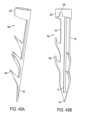
- FIGS. 49-52 illustrate a variety of alternative anchors that may be used in place of the anchors 16 shown in FIG. 7 .
- FIGS. 49A and 49B depict one such anchor 16a that is partially tubular or cylindrical in shape.
- This anchor has a first panel of material 120 that has a cylindrically curved outer surface and a second panel of material 122 that also has a cylindrically curved outer surface.
- a slot 17 runs in a front-to-back direction disposed between the first panel of material and the second panel of material.
- the pointy front end 46 of the anchor is configured for implantation into the annulus or the leaflets in a forward direction.
- There are also a plurality of barbs 48a that are configured so that subsequent to implantation, the barbs resist extraction of the anchor from the annulus or the leaflets in a backwards direction.
- this anchor 16a also has a ring-shaped portion 125 disposed at a back end of the anchor that connects the first panel of material 120 to the second panel of material 122.
- a front surface of the ring-shaped portion has a notch 128, and the slot 17 and the notch 128 are disposed on opposite sides of the ring-shaped portion 125.
- the outer surface of the barbs 48a is curved so as to follow the cylindrical curve of the outer surface of the panel of material to which it is attached (i.e., panels 120 and 122).
- This type of anchor 16a can be advantageously produced by cutting it out from a tube of material.
- Preferred materials for this anchor 16a include metals (e.g., steel alloys, stainless steel, nitinol), biocompatible plastics, and ceramics.
- the overall length of the anchor 16a is preferably between 3 and 30 mm, and more preferably between 5-10 mm.
- the diameter of the ring 125 is preferably between 0.5 and 5 mm, and more preferably between 1 and 2 mm.
- FIGS. 50A and 50B depict another anchor 16b that is partially tubular or cylindrical in shape.
- This anchor 16b also has a first panel of material 120 that has a cylindrically curved outer surface and a second panel of material 122 that also has a cylindrically curved outer surface.
- a slot 17 runs in a front-to-back direction disposed between the first panel of material and the second panel of material.
- the pointy front end 46 of the anchor is configured for implantation into the annulus or the leaflets in a forward direction.
- This anchor 16b has at least one tab 130 that is configured to automatically spring outward after being implanted, so that after the tab has sprung outward (as seen in FIG. 50B ), the tab causes the anchor to resist extraction from the annulus or the leaflets in a backwards direction. Note that prior to implantation, the tabs 130 remain in the collapsed state depicted in FIG. 50A and do not spring outward because they are restrained from doing so by a housing (such as the housing 24 shown in FIGS 4,
- this anchor 16b also preferably has a ring-shaped portion 125 disposed at a back end of the anchor that connects the first panel of material 120 to the second panel of material 122.
- a front surface of the ring-shaped portion has a notch 128, and wherein the slot 17 and the notch 128 are disposed on opposite sides of the ring-shaped portion 125.
- This type of anchor 16b can also be advantageously produced by cutting it out from a tube of material.
- the spring-out tabs 130 may be implemented using spring material or using a shape memory alloy. The preferred materials and dimensions for this design are similar to those for the design described above in connection with FIGS. 49A and 49B .
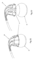
- FIGS. 51A and 51B depict another anchor 16c that is partially tubular or cylindrical in shape.
- This anchor 16c is similar to the anchor 16b depicted in FIGS. 50A and 50B , but instead of the tabs that are configured to automatically spring outward after being implanted, this anchor 16c uses one or more arms 145 formed from a shape-memory alloy (SMA) material. These arms are configured to automatically spring outward after being implanted by operation of the SMA material, so that after the arm has sprung outward (as seen in FIG. 51B ), the arm causes the anchor to resist extraction from the annulus or the leaflets in a backwards direction. Note that prior to implantation, the arms 145 remain in the collapsed state depicted in FIG.
- SMA shape-memory alloy
- This type of anchor 16c can also be advantageously produced by cutting it out from a tube of material.
- the preferred materials and dimensions for this design are also similar to those for the design described above in connection with FIGS. 49A and 49B .
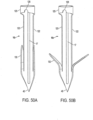
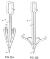
- FIGS. 52A and 52B depict yet another anchor 16d that may be used in place of the anchors 16 shown in FIG. 7 .
- This anchor 16d is similar to the anchor 16 depicted in FIG. 7 , but instead of the barb depicted in FIG. 7 , this anchor 16d uses one or more arms 140 formed from a shape-memory alloy (SMA) material. These arms are configured to automatically spring outward after being implanted by operation of the SMA material, so that after the arms 140 have sprung outward (as seen in FIG. 52B ), the arms cause the anchor to resist extraction from the annulus or the leaflets in a backwards direction. Note that prior to implantation, the arms 140 remain in the collapsed state depicted in FIG.
- SMA shape-memory alloy
- the preferred materials for this design are similar to those for the design described above in connection with FIGS. 49A and 49B .
- the length of the anchor 16d is preferably between 3 and 30 mm, more preferably between 5 and 10 mm.
- the thickness of the material is preferably between 0.1 and 1.5 mm, more preferably between 0.2 and 0.6 mm.
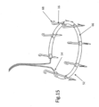
- FIG. 53 depicts a tissue engaging member that includes a loop of wire 14, a set of anchors 16 of the type depicted in FIG. 52B that have been implanted into a mitral valve annulus, with a plurality of tissue growth-promotion tubes 52 that are coaxially arranged about the loop of wire. Taken together, the loop of wire 14 and the plurality of tissue growth-promotion tubes 52 collectively form a loop of material.
- the usage and operation of this tissue engaging member is similar to the tissue engaging member discussed above in connection with FIG. 8 , and differs mainly because a different type of anchor is used. Of course, any of alternative anchors described herein may be used in place of the anchor depicted in FIG. 53 .
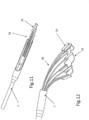
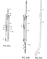
- FIGS. 54A and 54B illustrate a design of anchor launching mechanism for launching anchors 16 into the biovalve tissue, e.g. the Mitral valve annulus or leaflets.
- the anchor launching mechanism in includes a housing 24 that has an open front end.
- the housing has a cylindrical interior void that includes a first front section and a second rear section.
- An anchor 16 e.g., any of the anchors described above
- an anchor launching spring 26 is disposed in the rear portion of the void in the housing 24 in a compressed state.
- the spring 26 is preferably a coil spring.
- the back end (i.e., the proximal end) of the spring 26 is retained in housing 24 by a spring retention loop or hook 38.
- alternative configurations may be used for preventing the spring 26 from exiting the housing 24.
- the anchor launching mechanism includes an actuator configured to (a) prevent the spring from expanding from the compressed state prior to being actuated and (b) permit the spring to expand from the compressed state upon being actuated.
- the actuator is preferably implemented using an actuator 350 that initially passes coaxially through the anchor launching spring 26.
- Preferred materials for the actuator 350 include metals (e.g., steel alloys, stainless steel, nitinol), biocompatible plastics, and ceramics.
- the thickness of the actuator 350 is preferably between 0.05 and 1.0 mm, more preferably between 0.1 and 0.3 mm.
- the distal portion 355 of actuator 350 passes through and/or interfaces with an opening 30 in the housing.
- the distal portion 355 may be forked (as best seen in FIG. 54C ) to engage the opening 30 more securely.
- the front end (i.e., the distal end) of the spring 26 presses against the back end of the anchor 16.
- the back end of the anchor is the ring 125 located at the back of the anchor 16.
- the actuator 350 passes through the notch 128 in the ring 125 at the back of the anchor 16 and also passes through the opening 30 of the housing 24.
- distal portion 355 of the actuator 350 includes a fork-like tip for engaging the opening 30 of the housing 24 more securely.
- the passage of the distal portion 355 through the notch 128 and the opening 30 also operates to align the notch 128 with the opening 30.
- An actuation wire 28 (i.e., the "pull wire") is attached to the proximal portion of the actuator 350 using any suitable attachment approach (e.g., welding, crimping, etc.).
- the actuator 350 then can be pulled in a proximal direction by pulling on the pull wire 28.
- the distal portion 355 of actuator 350 is pulled inwardly through the opening 30 and is withdrawn from the opening 30.
- the spring 26 will expand into the front section of the housing 24 and push the anchor 16 forward such that at least a portion of the anchor 16 exits the front end of housing.
- the spring 26 pushes the anchor 16 with sufficient force to implant the anchor into the tissue.
- the discrete actuator can be eliminated, and the distal end of the actuation wire 28 itself can serve as the actuator. In either case, it is preferable to pull the wire 28 in the proximal direction with a jerk (i.e., with rapid acceleration), because it makes the launching more reliable and prevents the tissue engaging member from lifting away from the surface of the tissue prior to implantation.
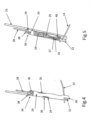
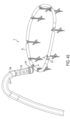
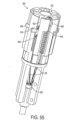
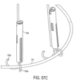
- FIG. 55 depicts an apparatus in accordance with an embodiment of the present invention for pulling the wires 28 in the proximal direction in this manner, to trigger the anchor launchers shown in FIGS. 54A and 54B .
- the pulling apparatus has a plurality of actuators housed in a housing 400. Each of these actuators is housed in a channel 402 that runs through the housing 400 in a proximal-to-distal direction.
- the housing 400 is cylindrical, and the channels 402 are distributed within the cylindrical housing close to the circumference of the cylinder.
- Each actuator has a shoulder 404 disposed adjacent to the channel 402.
- a compressed spring 406 is disposed in a distal portion of the channel.
- the distal end of the spring 406 is preferably fixed, and the proximal end is preferably movable.
- the channel 402 is configured to permit expansion of the spring 406 in a proximal direction.
- Each actuator also has a tab 408 that is affixed to the proximal end of the spring 406 using any suitable attachment system (e.g., screws, crimping, etc.).
- any suitable attachment system e.g., screws, crimping, etc.
- the tab may be affixed directly to the spring 406, or the tab may be connected through intermediate members.
- the tab 408 is configured to be movable between (1) a first position in which movement of the tab 408 in a proximal direction is blocked by the shoulder 404, and (2) a second position in which movement of the tab 408 in a proximal direction is not blocked by the shoulder 404. As soon as the tab 408 is moved from the first position to the second position, the spring 406 will expand within the channel and move from its compressed state to its released state, with the proximal end of the spring moving in a proximal direction.
- the proximal end of the pull wire 28 is attached (either directly or indirectly) to the spring 406 or the tab 408 and a distal portion of the pull wire 28 extends to the anchor launcher.
- the pull wire 28 is pulled in the proximal direction with the preferred jerking motion.
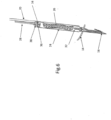
- the pull wires may be threaded though individual corresponding apertures to avoid tangling.
- a pull wire distribution collar 420 with respective distribution holes (not shown) disposed therein may be provided at the distal end of the housing 400.
- a rotatable cap may be is used to push the tabs from the first position to the second position.
- the interior surface of the cap has a cylindrical void configured to surround the cylindrical housing 400, and the interior surface has a single protrusion configured to sequentially push each of the tabs from the first position to the second position when the cap is rotated.
- the anchors will launch sequentially.
- the interior surface has a plurality of protrusions configured to simultaneously push a plurality of the tabs from the first position to the second position when the cap is rotated. In this case, a plurality of anchors will launch simultaneously.
- FIGS. 56A and 56B depict an alternative tissue engaging member.
- the tissue engaging member includes three sets of parts.
- the first set is a loop of material 160 configured to contact at least a portion of the annulus or the leaflets when the loop of material is deployed.
- This loop of material can be a wire, or in alternative designs the loop may be a different loop of material such as a tube, strip, chain, braid, etc., or a combination of multiple materials.
- the second set is a plurality of anchors 16, each of which has a pointy front end and a back end. Each of the anchors also has a slot 17 that runs in a front-to-back direction.
- the front ends of the anchors 16 are configured for implantation into the annulus or the leaflets in a forward direction.
- the anchors are configured so that subsequent to implantation, the anchors resist extraction from the annulus or the leaflets in a backwards direction.
- the anchor designs described above can be used for this purpose.
- the anchors are arranged with respect to the loop of material so that when the loop of material is deployed the anchors are distributed about the loop of material with the front ends of the anchors facing the annulus or the leaflets.
- the third set is a plurality of linking members 150 that are affixed to the loop of material 160. At least a portion of each of the linking members 150 passes through the slot in a respective anchor, and each of the linking members is configured to slide with respect to the slot in the respective anchor in the front-to-back direction.
- the linking members include a strip of material 155 that passes through the slot in the respective anchor. This strip of material 155 may be connected to the loop of material 160 through at least one intermediate member 152.
- the intermediate member 152 could be a C-shaped bracket that connects the loop of material 160 to the strip of material 155.
- the strip of material 155 may be directly connected to the loop of material 160.
- Preferred materials for the linking members 150 include metals (e.g., steel alloys, stainless steel, nitinol), biocompatible plastics, and ceramics.
- the width is preferably between 0.2 and 3 mm, more preferably between 0.5 and 1.5 mm.
- the thickness of the material is preferably between 0.05 and 1.0 mm, more preferably between 0.1 and 0.3 mm.
- the anchors and the linking members are disposed inside the loop at the inner circumference of the loop. In alternative designs (not shown), the anchors and the linking members may be disposed outside the loop at the outer circumference of the loop.
- the loop of material 160 Prior to launching, the loop of material 160 is delivered to its desired location in contact with the annulus or leaflets, in a manner similar to the designs described above.
- the anchors 16 are then launched (e.g., using any of the launching mechanisms described above).
- the anchors When the anchors are launched, the anchors will move forward while the strips 155 of the linking members 150 remain stationary. This will implant the tissue engaging member in the desired location.
- the linking members 150 will have shifted (with respect to the slot 17) from the front of the slot 17 towards the back of the slot 17.
- FIG. 56B differs from the FIG. 3 design because in the FIG. 56B design the loop of material 160 is connected to the slot 17 in the anchor via the linking members 150. In contrast, the loop of wire 14 passes directly through the slot in the anchor 16 in the FIG. 3 design.
- FIGS. 57A, 57B , and 57C show yet another design of an anchor, which relies on a component 316 that normally has the curled configuration shown in FIG. 57B .
- the anchor 316 is deformed and takes on a generally elongated shape shown in FIG. 57A .
- Housing 324 is preferably generally cylindrical in shape.
- a spring 326 is dispose in the proximal end of the housing 324, and the spring is configured to push the anchor 316 out of the housing 324 when it is triggered.
- the trigger mechanisms described above in connection with other designs may be used for this design.
- the anchor 316 Upon being launched, the anchor 316 is pushed out of the distal end of the housing 324 and will immediately spring back to its original curled configuration shown in FIG. 57B .
- the return to the original shape may be accomplished by forming the anchor 316 from a shape memory alloy.
- the distal tip 316b of the anchor 316 is preferably sharp, and is configured to pierce the tissue upon exiting the housing 324. The distal tip 316b will then curl around and engage the target tissue.
- anchor 3 16 preferably has a top portion 316a that forms a loop engaging eyelet, through which the loop of wire 314 is threaded, as seen in FIG. 57C _
- eyelets can also surround any tissue growth-promotion tubes (not shown) that may coaxially surround the loop 314.
- the loop 314 in this design is not positioned in contact with the tissue prior to launching. Instead, the loop 314 travels down to its final destination together with the eyelet of the top portion 316a during the implantation procedure.
- the delivery of the launch mechanism housings 324 to their intended locations prior to launching for this design may be implemented in similar ways to the other designs described herein.
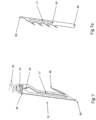
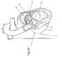
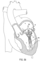
- FIG. 58 illustrates a design for implanting a ring and a valve in a single procedure.
- a tissue engaging member that includes anchors 16 and a loop 14 is mounted on anchor positioning leads 260 that extend from a delivery catheter C.
- the tissue engaging member is preferably inserted via the heart's apex, via an insertion catheter or encapsulating cylinder, together with an expandable valve 100.
- the valve 100 is located between the anchor positioning leads 260 in a collapsed state.
- a nose cone 250 may be used to help guide the tissue engaging member to the correct location.
- valve 1 00 is advanced to a location within the loop 14 and expanded from its original collapsed state (depicted in FIG. 38 ) to its final expanded configuration (depicted in FIGS. 39 and 37 ).
- the insertion catheter and encapsulating cylinder 102 are then removed, leaving the tissue engaging member and the valve 100 behind.
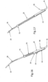
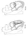
- FIG. 59 shows a design wherein the anchor positioning leads 260 are implemented in the form of elongated needle-like members.
- the elongated needle-like anchor positioning leads are stiff enough so that they can press the anchors 16 directly into the bio-tissue, without relying on a spring-based anchor launching mechanism.
- FIG. 60 shows the situation after the anchor positioning leads 260 have been removed from the heart.
Landscapes
- Health & Medical Sciences (AREA)
- Cardiology (AREA)
- Life Sciences & Earth Sciences (AREA)
- Engineering & Computer Science (AREA)
- General Health & Medical Sciences (AREA)
- Biomedical Technology (AREA)
- Heart & Thoracic Surgery (AREA)
- Veterinary Medicine (AREA)
- Public Health (AREA)
- Animal Behavior & Ethology (AREA)
- Vascular Medicine (AREA)
- Oral & Maxillofacial Surgery (AREA)
- Transplantation (AREA)
- Surgery (AREA)
- Nuclear Medicine, Radiotherapy & Molecular Imaging (AREA)
- Medical Informatics (AREA)
- Molecular Biology (AREA)
- Prostheses (AREA)
Claims (5)
- Vorrichtung zum Auslösen mehrerer Ankerwerfer durch Ziehen an Zugdrähten (28), die sich zu den Ankerwerfern erstrecken, wobei die Vorrichtung umfasst:
mehrere in einem Gehäuse (400) untergebrachte Aktoren, wobei jeder der Aktoren aufweist(a) einen Kanal (402), der durch das Gehäuse (400) in einer Richtung von proximal nach distal verläuft,(b) eine Schulter (404), die benachbart zu dem Kanal (402) angeordnet ist,(c) eine komprimierte Feder (406), die in einem distalen Abschnitt des Kanals (402) angeordnet ist, wobei die Feder (406) ein festes distales Ende und ein bewegliches proximales Ende aufweist und der Kanal (402) dazu konfiguriert ist, eine Ausdehnung der Feder (406) in einer proximalen Richtung zu ermöglichen,(d) eine Lasche (408), die an dem proximalen Ende der Feder (406) befestigt ist, wobei die Lasche (408) dazu konfiguriert ist, zwischen einer ersten Position, in der die Bewegung der Lasche (408) in einer proximalen Richtung durch die Schulter (404) blockiert ist, und einer zweiten Position, in der die Bewegung der Lasche (408) in einer proximalen Richtung nicht durch die Schulter (404) blockiert ist, beweglich zu sein,
wobei der Kanal (402), die Schulter (404), die Feder (406) und die Lasche (408) so konfiguriert sind, dass dann, wenn die Lasche (408) von der ersten Position in die zweite Position bewegt wird, die Feder (406) innerhalb des Kanals (402) expandiert, wobei sich das proximale Ende der Feder (406) in eine proximale Richtung bewegt, und(e) einen Zugdraht (28) mit einem proximalen Ende, das an der Feder (406) oder der Lasche (408) befestigt ist, und einem distalen Abschnitt, der sich zu dem Ankerwerfer erstreckt, wobei dann, wenn sich das proximale Ende der Feder (406) in die proximale Richtung bewegt, der Zugdraht (28) in die proximale Richtung gezogen wird, wodurch die Ankerwerfer durch Ziehen der Zugdrähte (28), die sich zu den Ankerwerfern erstrecken, ausgelöst werden. - Vorrichtung nach Anspruch 1, wobei das Gehäuse (400) zylindrisch ist, die Kanäle (402) innerhalb des Gehäuses (400) verteilt sind und die Laschen (408) sich außerhalb eines Umfangs des Gehäuses (400) erstrecken.
- Vorrichtung nach Anspruch 2, ferner umfassend:
eine drehbare Kappe, wobei eine Innenfläche der Kappe einen zylindrischen Hohlraum definiert, der dazu konfiguriert ist, das Gehäuse (400) zu umgeben, wobei die Innenfläche einen einzelnen Vorsprung aufweist, der so konfiguriert ist, dass er nacheinander jede der Laschen (408) von der ersten Position in die zweite Position schiebt, wenn die Kappe gedreht wird. - Vorrichtung nach Anspruch 2, ferner umfassend:
eine drehbare Kappe, wobei eine Innenfläche der Kappe einen zylindrischen Hohlraum definiert, der dazu konfiguriert ist, das Gehäuse (400) zu umgeben, wobei die Innenfläche mehrere Vorsprünge aufweist, die so konfiguriert sind, dass sie gleichzeitig mehrere der Laschen (408) von der ersten Position in die zweite Position schieben, wenn die Kappe gedreht wird. - Vorrichtung nach Anspruch 1, wobei das proximale Ende des Zugdrahtes (28) direkt an der Feder (406) oder der Lasche (408) befestigt ist.
Applications Claiming Priority (3)
| Application Number | Priority Date | Filing Date | Title |
|---|---|---|---|
| US201361831632P | 2013-06-06 | 2013-06-06 | |
| EP14741656.4A EP3003221B1 (de) | 2013-06-06 | 2014-06-03 | Herzklappenreparatur und -ersatz |
| PCT/IB2014/000949 WO2014195786A2 (en) | 2013-06-06 | 2014-06-03 | Heart valve repair and replacement |
Related Parent Applications (1)
| Application Number | Title | Priority Date | Filing Date |
|---|---|---|---|
| EP14741656.4A Division EP3003221B1 (de) | 2013-06-06 | 2014-06-03 | Herzklappenreparatur und -ersatz |
Publications (2)
| Publication Number | Publication Date |
|---|---|
| EP3597151A1 EP3597151A1 (de) | 2020-01-22 |
| EP3597151B1 true EP3597151B1 (de) | 2024-08-07 |
Family
ID=51211803
Family Applications (3)
| Application Number | Title | Priority Date | Filing Date |
|---|---|---|---|
| EP19193908.1A Active EP3597150B1 (de) | 2013-06-06 | 2014-06-03 | Herzklappenreparatur und -ersatz |
| EP19193911.5A Active EP3597151B1 (de) | 2013-06-06 | 2014-06-03 | Herzklappenreparatur und -ersatz |
| EP14741656.4A Active EP3003221B1 (de) | 2013-06-06 | 2014-06-03 | Herzklappenreparatur und -ersatz |
Family Applications Before (1)
| Application Number | Title | Priority Date | Filing Date |
|---|---|---|---|
| EP19193908.1A Active EP3597150B1 (de) | 2013-06-06 | 2014-06-03 | Herzklappenreparatur und -ersatz |
Family Applications After (1)
| Application Number | Title | Priority Date | Filing Date |
|---|---|---|---|
| EP14741656.4A Active EP3003221B1 (de) | 2013-06-06 | 2014-06-03 | Herzklappenreparatur und -ersatz |
Country Status (6)
| Country | Link |
|---|---|
| US (3) | US10206776B2 (de) |
| EP (3) | EP3597150B1 (de) |
| JP (3) | JP6440694B2 (de) |
| CN (2) | CN105392449B (de) |
| CA (2) | CA3005848C (de) |
| WO (1) | WO2014195786A2 (de) |
Families Citing this family (166)
| Publication number | Priority date | Publication date | Assignee | Title |
|---|---|---|---|---|
| US20050137687A1 (en) | 2003-12-23 | 2005-06-23 | Sadra Medical | Heart valve anchor and method |
| US7959666B2 (en) * | 2003-12-23 | 2011-06-14 | Sadra Medical, Inc. | Methods and apparatus for endovascularly replacing a heart valve |
| DE102005003632A1 (de) | 2005-01-20 | 2006-08-17 | Fraunhofer-Gesellschaft zur Förderung der angewandten Forschung e.V. | Katheter für die transvaskuläre Implantation von Herzklappenprothesen |
| WO2006097931A2 (en) | 2005-03-17 | 2006-09-21 | Valtech Cardio, Ltd. | Mitral valve treatment techniques |
| US8951285B2 (en) | 2005-07-05 | 2015-02-10 | Mitralign, Inc. | Tissue anchor, anchoring system and methods of using the same |
| WO2007097983A2 (en) * | 2006-02-14 | 2007-08-30 | Sadra Medical, Inc. | Systems and methods for delivering a medical implant |
| US9974653B2 (en) | 2006-12-05 | 2018-05-22 | Valtech Cardio, Ltd. | Implantation of repair devices in the heart |
| US11259924B2 (en) | 2006-12-05 | 2022-03-01 | Valtech Cardio Ltd. | Implantation of repair devices in the heart |
| US11660190B2 (en) | 2007-03-13 | 2023-05-30 | Edwards Lifesciences Corporation | Tissue anchors, systems and methods, and devices |
| US7896915B2 (en) | 2007-04-13 | 2011-03-01 | Jenavalve Technology, Inc. | Medical device for treating a heart valve insufficiency |
| BR112012021347A2 (pt) | 2008-02-26 | 2019-09-24 | Jenavalve Tecnology Inc | stent para posicionamento e ancoragem de uma prótese valvular em um local de implantação no coração de um paciente |
| US9044318B2 (en) | 2008-02-26 | 2015-06-02 | Jenavalve Technology Gmbh | Stent for the positioning and anchoring of a valvular prosthesis |
| US8382829B1 (en) | 2008-03-10 | 2013-02-26 | Mitralign, Inc. | Method to reduce mitral regurgitation by cinching the commissure of the mitral valve |
| EP3628362B1 (de) | 2008-06-16 | 2023-10-25 | Edwards Lifesciences Innovation (Israel) Ltd. | Annuloplastievorrichtungen |
| CN102341063B (zh) | 2008-12-22 | 2015-11-25 | 瓦尔泰克卡迪欧有限公司 | 可调瓣环成形装置及其调节机构 |
| US8911494B2 (en) | 2009-05-04 | 2014-12-16 | Valtech Cardio, Ltd. | Deployment techniques for annuloplasty ring |
| US10517719B2 (en) | 2008-12-22 | 2019-12-31 | Valtech Cardio, Ltd. | Implantation of repair devices in the heart |
| US8147542B2 (en) | 2008-12-22 | 2012-04-03 | Valtech Cardio, Ltd. | Adjustable repair chords and spool mechanism therefor |
| US8241351B2 (en) | 2008-12-22 | 2012-08-14 | Valtech Cardio, Ltd. | Adjustable partial annuloplasty ring and mechanism therefor |
| US9011530B2 (en) | 2008-12-22 | 2015-04-21 | Valtech Cardio, Ltd. | Partially-adjustable annuloplasty structure |
| US8715342B2 (en) | 2009-05-07 | 2014-05-06 | Valtech Cardio, Ltd. | Annuloplasty ring with intra-ring anchoring |
| US8353956B2 (en) | 2009-02-17 | 2013-01-15 | Valtech Cardio, Ltd. | Actively-engageable movement-restriction mechanism for use with an annuloplasty structure |
| US9968452B2 (en) | 2009-05-04 | 2018-05-15 | Valtech Cardio, Ltd. | Annuloplasty ring delivery cathethers |
| US12485010B2 (en) | 2009-05-07 | 2025-12-02 | Edwards Lifesciences Innovation (Israel) Ltd. | Multiple anchor delivery tool |
| US9180007B2 (en) | 2009-10-29 | 2015-11-10 | Valtech Cardio, Ltd. | Apparatus and method for guide-wire based advancement of an adjustable implant |
| US10098737B2 (en) | 2009-10-29 | 2018-10-16 | Valtech Cardio, Ltd. | Tissue anchor for annuloplasty device |
| US9011520B2 (en) | 2009-10-29 | 2015-04-21 | Valtech Cardio, Ltd. | Tissue anchor for annuloplasty device |
| US8734467B2 (en) | 2009-12-02 | 2014-05-27 | Valtech Cardio, Ltd. | Delivery tool for implantation of spool assembly coupled to a helical anchor |
| US8870950B2 (en) | 2009-12-08 | 2014-10-28 | Mitral Tech Ltd. | Rotation-based anchoring of an implant |
| US8579964B2 (en) | 2010-05-05 | 2013-11-12 | Neovasc Inc. | Transcatheter mitral valve prosthesis |
| US10856978B2 (en) | 2010-05-20 | 2020-12-08 | Jenavalve Technology, Inc. | Catheter system |
| JP2013526388A (ja) | 2010-05-25 | 2013-06-24 | イエナバルブ テクノロジー インク | 人工心臓弁、及び人工心臓弁とステントを備える経カテーテル搬送体内プロテーゼ |
| US11653910B2 (en) | 2010-07-21 | 2023-05-23 | Cardiovalve Ltd. | Helical anchor implantation |
| US9308087B2 (en) | 2011-04-28 | 2016-04-12 | Neovasc Tiara Inc. | Sequentially deployed transcatheter mitral valve prosthesis |
| US9554897B2 (en) | 2011-04-28 | 2017-01-31 | Neovasc Tiara Inc. | Methods and apparatus for engaging a valve prosthesis with tissue |
| US9402721B2 (en) | 2011-06-01 | 2016-08-02 | Valcare, Inc. | Percutaneous transcatheter repair of heart valves via trans-apical access |
| EP3725269A1 (de) | 2011-06-23 | 2020-10-21 | Valtech Cardio, Ltd. | Verschlusselement zur verwendung mit einer annuloplastiestruktur |
| US10792152B2 (en) | 2011-06-23 | 2020-10-06 | Valtech Cardio, Ltd. | Closed band for percutaneous annuloplasty |
| US9918840B2 (en) | 2011-06-23 | 2018-03-20 | Valtech Cardio, Ltd. | Closed band for percutaneous annuloplasty |
| US8858623B2 (en) | 2011-11-04 | 2014-10-14 | Valtech Cardio, Ltd. | Implant having multiple rotational assemblies |
| EP2775896B1 (de) | 2011-11-08 | 2020-01-01 | Valtech Cardio, Ltd. | Gesteuerte lenkfunktionalität für ein implantatabgabewerkzeug |
| US10398555B2 (en) | 2011-12-12 | 2019-09-03 | Cardiac Implants Llc | Magnetically coupled cinching of a loop installed in a valve annulus |
| JP6153938B2 (ja) | 2011-12-12 | 2017-06-28 | デイヴィッド・アロン | 心臓弁修復デバイス |
| US9839519B2 (en) | 2012-02-29 | 2017-12-12 | Valcare, Inc. | Percutaneous annuloplasty system with anterior-posterior adjustment |
| US9180008B2 (en) | 2012-02-29 | 2015-11-10 | Valcare, Inc. | Methods, devices, and systems for percutaneously anchoring annuloplasty rings |
| US9345573B2 (en) | 2012-05-30 | 2016-05-24 | Neovasc Tiara Inc. | Methods and apparatus for loading a prosthesis onto a delivery system |
| US10849755B2 (en) | 2012-09-14 | 2020-12-01 | Boston Scientific Scimed, Inc. | Mitral valve inversion prostheses |
| US10543088B2 (en) | 2012-09-14 | 2020-01-28 | Boston Scientific Scimed, Inc. | Mitral valve inversion prostheses |
| EP2900150B1 (de) | 2012-09-29 | 2018-04-18 | Mitralign, Inc. | System zur abgabe von plikationssperren |
| EP3730066A1 (de) | 2012-10-23 | 2020-10-28 | Valtech Cardio, Ltd. | Perkutane gewebeankertechniken |
| EP2911594B1 (de) | 2012-10-23 | 2018-12-05 | Valtech Cardio, Ltd. | Gesteuerte lenkfunktionalität für ein implantateinführungswerkzeug |
| WO2014087402A1 (en) | 2012-12-06 | 2014-06-12 | Valtech Cardio, Ltd. | Techniques for guide-wire based advancement of a tool |
| US20150351906A1 (en) | 2013-01-24 | 2015-12-10 | Mitraltech Ltd. | Ventricularly-anchored prosthetic valves |
| EP2961351B1 (de) | 2013-02-26 | 2018-11-28 | Mitralign, Inc. | Vorrichtungen zur perkutanen reparatur der trikuspidalklappe |
| US10449333B2 (en) | 2013-03-14 | 2019-10-22 | Valtech Cardio, Ltd. | Guidewire feeder |
| EP3804646B1 (de) | 2013-03-15 | 2024-11-13 | Valcare Medical, Inc. | Systeme zur verabreichung von annuloplastieringen |
| WO2014152503A1 (en) | 2013-03-15 | 2014-09-25 | Mitralign, Inc. | Translation catheters, systems, and methods of use thereof |
| US9572665B2 (en) | 2013-04-04 | 2017-02-21 | Neovasc Tiara Inc. | Methods and apparatus for delivering a prosthetic valve to a beating heart |
| US10813751B2 (en) | 2013-05-22 | 2020-10-27 | Valcare, Inc. | Transcatheter prosthetic valve for mitral or tricuspid valve replacement |
| WO2014190329A1 (en) | 2013-05-24 | 2014-11-27 | Valcare, Inc. | Heart and peripheral vascular valve replacement in conjunction with a support ring |
| CN105392449B (zh) | 2013-06-06 | 2017-09-05 | 戴维·阿隆 | 心脏瓣膜修复和更换 |
| US11058417B2 (en) | 2013-06-28 | 2021-07-13 | Valcare, Inc. | Device, system, and method to secure an article to a tissue |
| EP4098226A1 (de) | 2013-08-30 | 2022-12-07 | JenaValve Technology, Inc. | Endoprothese mit einem radial zusammenklappbaren rahmen und einer klappenprothese |
| US10070857B2 (en) | 2013-08-31 | 2018-09-11 | Mitralign, Inc. | Devices and methods for locating and implanting tissue anchors at mitral valve commissure |
| WO2015059699A2 (en) | 2013-10-23 | 2015-04-30 | Valtech Cardio, Ltd. | Anchor magazine |
| US9610162B2 (en) | 2013-12-26 | 2017-04-04 | Valtech Cardio, Ltd. | Implantation of flexible implant |
| USD790705S1 (en) * | 2014-03-29 | 2017-06-27 | Cormatrix Cardiovascular, Inc | Prosthetic tissue valve |
| USD790706S1 (en) * | 2014-03-29 | 2017-06-27 | Cormatrix Cardiovascular, Inc. | Prosthetic tissue valve |
| US10687815B2 (en) * | 2014-07-02 | 2020-06-23 | Medtentia International Ltd Oy | Clip for a medical implant |
| US9180005B1 (en) | 2014-07-17 | 2015-11-10 | Millipede, Inc. | Adjustable endolumenal mitral valve ring |
| EP4066786B1 (de) | 2014-07-30 | 2025-05-14 | Cardiovalve Ltd. | Gelenkbare klappenprothese |
| EP3206629B1 (de) | 2014-10-14 | 2021-07-14 | Valtech Cardio, Ltd. | Vorrichtung zur rückhaltung von herzklappensegel |
| ES2978714T3 (es) | 2015-02-05 | 2024-09-18 | Cardiovalve Ltd | Válvula protésica con marcos de deslizamiento axial |
| WO2016130991A1 (en) | 2015-02-13 | 2016-08-18 | Millipede, Inc. | Valve replacement using rotational anchors |
| US20160256269A1 (en) | 2015-03-05 | 2016-09-08 | Mitralign, Inc. | Devices for treating paravalvular leakage and methods use thereof |
| WO2016150806A1 (en) | 2015-03-20 | 2016-09-29 | Jenavalve Technology, Inc. | Heart valve prosthesis delivery system and method for delivery of heart valve prosthesis with introducer sheath |
| CN107847320B (zh) | 2015-04-30 | 2020-03-17 | 瓦尔泰克卡迪欧有限公司 | 瓣膜成形术技术 |
| JP6767388B2 (ja) | 2015-05-01 | 2020-10-14 | イェーナヴァルヴ テクノロジー インコーポレイテッド | 心臓弁置換におけるペースメーカー割合を低減させるデバイス及び方法 |
| DE102015107242B4 (de) * | 2015-05-08 | 2022-11-03 | Highlife Sas | System zum Implantieren eines Implantats um eine umfängliche Gewebestruktur in einem Herz und Verfahren zum Anordnen und Vorbringen eines Implantats auf einem Führungsdraht eines solchen Systems |
| EP3313296B1 (de) * | 2015-06-23 | 2019-07-31 | Heartware, Inc. | Anker oder klammer mit widerhaken |
| US10335275B2 (en) | 2015-09-29 | 2019-07-02 | Millipede, Inc. | Methods for delivery of heart valve devices using intravascular ultrasound imaging |
| CN111329541B (zh) | 2015-11-17 | 2023-09-19 | 波士顿科学国际有限公司 | 用于使心脏瓣环重新定形的可植入装置和输送系统 |
| EP3386437A4 (de) * | 2015-12-07 | 2020-03-25 | Micro Interventional Devices, Inc. | Fixierung einer prothese an gewebe |
| CN113069242A (zh) | 2015-12-15 | 2021-07-06 | 内奥瓦斯克迪亚拉公司 | 经中隔递送系统 |
| US10828160B2 (en) | 2015-12-30 | 2020-11-10 | Edwards Lifesciences Corporation | System and method for reducing tricuspid regurgitation |
| US10751182B2 (en) | 2015-12-30 | 2020-08-25 | Edwards Lifesciences Corporation | System and method for reshaping right heart |
| JP7006940B2 (ja) | 2016-01-29 | 2022-01-24 | ニオバスク ティアラ インコーポレイテッド | 流出の閉塞を回避するための人工弁 |
| US10531866B2 (en) | 2016-02-16 | 2020-01-14 | Cardiovalve Ltd. | Techniques for providing a replacement valve and transseptal communication |
| EP4183371A1 (de) | 2016-05-13 | 2023-05-24 | JenaValve Technology, Inc. | Herzklappenprotheseneinführungssystem und verfahren zur einführung einer herzklappenprothese mit einführschleuse und ladesystem |
| US9517130B1 (en) * | 2016-05-24 | 2016-12-13 | Cardiac Implants Llc | Implanting a cinching cord into a cardiac valve annulus |
| US10702274B2 (en) | 2016-05-26 | 2020-07-07 | Edwards Lifesciences Corporation | Method and system for closing left atrial appendage |
| GB201611910D0 (en) | 2016-07-08 | 2016-08-24 | Valtech Cardio Ltd | Adjustable annuloplasty device with alternating peaks and troughs |
| US20190231525A1 (en) | 2016-08-01 | 2019-08-01 | Mitraltech Ltd. | Minimally-invasive delivery systems |
| CN114587712B (zh) | 2016-08-10 | 2025-08-29 | 卡迪尔维尔福股份有限公司 | 具有同轴框架的人工瓣膜 |
| CN107753153B (zh) | 2016-08-15 | 2022-05-31 | 沃卡尔有限公司 | 用于治疗心脏瓣膜关闭不全的装置和方法 |
| EP3512465B1 (de) | 2016-09-15 | 2021-09-01 | Cardiac Implants LLC | Vorrichtung zum einführen eines herz-annulusringes |
| KR102282985B1 (ko) | 2016-10-31 | 2021-07-30 | 카디악 임플란츠 엘엘씨 | 심장 판막 고리 상으로의 설치 전에 수축 코드 또는 환형 링의 위치를 드러내기 위한 가요성 방사선 불투과성 돌출부 |
| US20180140419A1 (en) | 2016-11-21 | 2018-05-24 | Neovasc Tiara Inc. | Methods and systems for rapid retraction of a transcatheter heart valve delivery system |
| FR3060292B1 (fr) * | 2016-12-15 | 2019-01-25 | Cmi'nov | Dispositif pour realiser ou preparer une annuloplastie mitrale par voie transfemorale |
| CN110392557A (zh) | 2017-01-27 | 2019-10-29 | 耶拿阀门科技股份有限公司 | 心脏瓣膜模拟 |
| WO2018148584A1 (en) | 2017-02-10 | 2018-08-16 | Millipede, Inc. | Implantable device and delivery system for reshaping a heart valve annulus |
| CN108618871A (zh) | 2017-03-17 | 2018-10-09 | 沃卡尔有限公司 | 具有多方向锚部的二尖瓣或三尖瓣修复系统 |
| DE102017002976B4 (de) * | 2017-03-28 | 2021-08-26 | Immanuel Albertinen Diakonie Ggmbh | Minimal-invasiv implantierbare Vorrichtung zur Beseitigung einer Mitralklappeninsuffizienz am schlagenden Herzen und Mitralklappen-Implantat-System |
| CN120477688A (zh) * | 2017-03-29 | 2025-08-15 | 波士顿科学国际有限公司 | 用于组织牵开的装置和方法 |
| US11045627B2 (en) | 2017-04-18 | 2021-06-29 | Edwards Lifesciences Corporation | Catheter system with linear actuation control mechanism |
| WO2018231280A1 (en) | 2017-06-14 | 2018-12-20 | Cardiac Implants Llc | Constricting a cardiac valve annulus and installing a ring onto a cardiac valve annulus |
| US11793633B2 (en) | 2017-08-03 | 2023-10-24 | Cardiovalve Ltd. | Prosthetic heart valve |
| US12064347B2 (en) | 2017-08-03 | 2024-08-20 | Cardiovalve Ltd. | Prosthetic heart valve |
| CA3073834A1 (en) | 2017-08-25 | 2019-02-28 | Neovasc Tiara Inc. | Sequentially deployed transcatheter mitral valve prosthesis |
| US12458493B2 (en) | 2017-09-19 | 2025-11-04 | Cardiovalve Ltd. | Prosthetic heart valve and delivery systems and methods |
| US10835221B2 (en) | 2017-11-02 | 2020-11-17 | Valtech Cardio, Ltd. | Implant-cinching devices and systems |
| CN108013953B (zh) * | 2017-11-08 | 2020-01-17 | 中国医学科学院阜外医院 | 瓣膜成形环调节装置及其成形环 |
| US11135062B2 (en) | 2017-11-20 | 2021-10-05 | Valtech Cardio Ltd. | Cinching of dilated heart muscle |
| JP7244524B2 (ja) | 2018-01-03 | 2023-03-22 | カーディアック・インプランツ・エルエルシー | 心臓弁輪の周りに縮径状態で締付コードを保持するための留め具、および留め具の取り付け |
| US10980635B2 (en) * | 2018-01-07 | 2021-04-20 | William Joseph Drasler | Annuloplasty device and methods |
| WO2019145947A1 (en) | 2018-01-24 | 2019-08-01 | Valtech Cardio, Ltd. | Contraction of an annuloplasty structure |
| EP4248904A3 (de) | 2018-01-26 | 2023-11-29 | Edwards Lifesciences Innovation (Israel) Ltd. | Techniken zur erleichterung von herzklappen-tethering und sehnenaustausch |
| CN110101486B (zh) | 2018-02-01 | 2024-02-27 | 上海微创心通医疗科技有限公司 | 心脏瓣膜假体及其输送器 |
| CA3097677A1 (en) | 2018-04-25 | 2019-10-31 | Endomatic Ltd. | Suturing clip |
| CN112423709A (zh) * | 2018-05-18 | 2021-02-26 | 万能医药公司 | 心脏瓣膜修复的方法和装置 |
| JP7387731B2 (ja) | 2018-07-12 | 2023-11-28 | エドワーズ ライフサイエンシーズ イノベーション (イスラエル) リミテッド | 弁輪形成システムおよびそのための係止ツール |
| EP3876870B1 (de) | 2018-11-08 | 2023-12-20 | Neovasc Tiara Inc. | Ventrikuläres einsetzen einer transkathetermitralklappenprothese |
| CA3120462A1 (en) | 2018-11-29 | 2020-06-04 | Cardiomech As | Device for heart repair |
| IL283647B2 (en) | 2018-12-03 | 2025-10-01 | Valcare Inc | Stabilization and adjustment tool for controlling the minimally invasive bicuspid/tricuspid valve repair system |
| AU2020233892A1 (en) | 2019-03-08 | 2021-11-04 | Neovasc Tiara Inc. | Retrievable prosthesis delivery system |
| AU2020256195B2 (en) | 2019-04-01 | 2022-10-13 | Neovasc Tiara Inc. | Controllably deployable prosthetic valve |
| CN113924065B (zh) | 2019-04-10 | 2026-01-30 | 内奥瓦斯克迪亚拉公司 | 具有自然血流的假体瓣膜 |
| US11779742B2 (en) | 2019-05-20 | 2023-10-10 | Neovasc Tiara Inc. | Introducer with hemostasis mechanism |
| SG11202112651QA (en) | 2019-05-29 | 2021-12-30 | Valtech Cardio Ltd | Tissue anchor handling systems and methods |
| CN113747859B (zh) | 2019-06-11 | 2025-02-28 | 沃卡尔医药有限公司 | 用于微创治疗的具有后瓣叶的瓣环成形环 |
| EP3982844A4 (de) | 2019-06-11 | 2023-05-10 | Valcare, Inc. | Systeme und verfahren zur einführung eines sehnenfadenersatzsystems |
| US11311376B2 (en) | 2019-06-20 | 2022-04-26 | Neovase Tiara Inc. | Low profile prosthetic mitral valve |
| CN114173713A (zh) * | 2019-07-15 | 2022-03-11 | 沃卡尔有限公司 | 经导管生物假体构件和支撑结构 |
| CN114423356B (zh) | 2019-07-16 | 2024-12-27 | 爱德华兹生命科学公司 | 组织重塑的系统和方法 |
| CA3141295A1 (en) | 2019-07-23 | 2021-01-28 | Valtech Cardio, Ltd. | Contraction of an annuloplasty structure |
| US12364606B2 (en) | 2019-07-23 | 2025-07-22 | Edwards Lifesciences Innovation (Israel) Ltd. | Fluoroscopic visualization of heart valve anatomy |
| CN114173714A (zh) * | 2019-08-05 | 2022-03-11 | 波士顿科学国际有限公司 | 用于瓣膜修复装置的框架释放机构 |
| US11672661B2 (en) | 2019-08-22 | 2023-06-13 | Silara Medtech Inc. | Annuloplasty systems and methods |
| CN114258313A (zh) | 2019-08-28 | 2022-03-29 | 瓦尔泰克卡迪欧有限公司 | 低剖面可转向导管 |
| CN114423381A (zh) | 2019-08-30 | 2022-04-29 | 瓦尔泰克卡迪欧有限公司 | 锚通道尖端 |
| CA3155254A1 (en) * | 2019-09-25 | 2021-04-01 | Cardiac Implants Llc | Cardiac valve annulus reduction system |
| AU2020375903B2 (en) | 2019-10-29 | 2025-10-30 | Edwards Lifesciences Innovation (Israel) Ltd. | Annuloplasty and tissue anchor technologies |
| CN110772357B (zh) * | 2019-12-03 | 2024-09-24 | 青岛心血管病医院有限公司 | 一种瓣环成形环用锚固装置及其锚固方法 |
| WO2021111451A1 (en) * | 2019-12-03 | 2021-06-10 | Vvital Biomed Ltd | Device, system and method for transcatheter mitral and tricuspid valve repair |
| WO2021236634A2 (en) | 2020-05-20 | 2021-11-25 | Cardiac Implants, Llc | Reducing the diameter of a cardiac valve annulus with independent control over each of the anchors that are launched into the annulus |
| WO2021255533A1 (en) | 2020-06-19 | 2021-12-23 | Valtech Cardio Ltd. | Self-stopping tissue anchors |
| CN113413241B (zh) * | 2020-08-31 | 2025-04-04 | 宁波健世科技股份有限公司 | 一种可多点连续定位锚定的植入器械系统 |
| US11173028B1 (en) | 2020-09-09 | 2021-11-16 | Cardiac Implants Llc | Positioning a medical device in the right atrium or right ventricle using a non-flexible catheter |
| WO2022086769A1 (en) * | 2020-10-19 | 2022-04-28 | Silara Medtech Inc. | Annuloplasty device, cinching device and method of annuloplasty |
| GB2601146B (en) * | 2020-11-19 | 2023-02-22 | Cardiomech As | Device for heart repair |
| US12357459B2 (en) | 2020-12-03 | 2025-07-15 | Cardiovalve Ltd. | Transluminal delivery system |
| CN117157033A (zh) * | 2021-02-09 | 2023-12-01 | 爱德华兹生命科学创新(以色列)有限公司 | 用于心脏瓣膜修复的系统和设备 |
| WO2022178042A1 (en) * | 2021-02-16 | 2022-08-25 | Conkay Medical Systems, Inc. | Devices, systems, and methods for treating conditions of the heart |
| US20230045532A1 (en) * | 2021-08-09 | 2023-02-09 | Valcare, Inc. | Systems and methods for target/article bridging engagement and anchoring |
| EP4432931A1 (de) * | 2021-11-16 | 2024-09-25 | Edwards Lifesciences Corporation | Vorrichtung zum falten von klappensegeln |
| WO2023105523A1 (en) * | 2021-12-07 | 2023-06-15 | Endomatic Ltd. | Anchors for a collapsing implant |
| CN115054406B (zh) * | 2022-06-01 | 2026-01-02 | 上海以心医疗器械有限公司 | 锚钩组件及锚钩弹射装置 |
| CN115120388B (zh) * | 2022-06-01 | 2025-11-28 | 上海以心医疗器械有限公司 | 锚钩组件及其螺旋输送装置 |
| US12484893B2 (en) | 2022-06-30 | 2025-12-02 | Medos International Sàrl | Multispan cinchable loops for knotless spanning of tissue between anchor points and tools for using the same |
| US12171658B2 (en) | 2022-11-09 | 2024-12-24 | Jenavalve Technology, Inc. | Catheter system for sequential deployment of an expandable implant |
| CA3228597A1 (en) | 2023-02-10 | 2025-04-28 | Vesalius Cardiovascular Inc. | Apparatus and methods for the delivery of biocompatible materials |
| CN118717199B (zh) * | 2023-03-28 | 2025-09-02 | 宁波健世科技股份有限公司 | 一种锚定系统 |
| US12036120B1 (en) | 2023-08-30 | 2024-07-16 | Vesalius Cardiovascular Inc. | Lock delivery system |
| WO2025219808A1 (en) * | 2024-04-16 | 2025-10-23 | Edwards Lifesciences Innovation (Israel) Ltd. | Valve-spanning tethers |
| US12514705B2 (en) | 2024-05-29 | 2026-01-06 | Vesalius Cardiovascular Inc. | Heart valve repair apparatus |
| CN121242652B (zh) * | 2025-12-04 | 2026-03-17 | 国家心血管病中心 | 适用于将锚钉设置于瓣环组织上的装置 |
Family Cites Families (62)
| Publication number | Priority date | Publication date | Assignee | Title |
|---|---|---|---|---|
| US688592A (en) | 1900-12-03 | 1901-12-10 | Robert Chadwick | Fire-escape. |
| US4042979A (en) | 1976-07-12 | 1977-08-23 | Angell William W | Valvuloplasty ring and prosthetic method |
| US5683366A (en) | 1992-01-07 | 1997-11-04 | Arthrocare Corporation | System and method for electrosurgical tissue canalization |
| US6620155B2 (en) | 1996-07-16 | 2003-09-16 | Arthrocare Corp. | System and methods for electrosurgical tissue contraction within the spine |
| US7214230B2 (en) * | 1998-02-24 | 2007-05-08 | Hansen Medical, Inc. | Flexible instrument |
| US6306163B1 (en) | 1998-08-04 | 2001-10-23 | Advanced Cardiovascular Systems, Inc. | Assembly for collecting emboli and method of use |
| US20050283189A1 (en) * | 1999-03-31 | 2005-12-22 | Rosenblatt Peter L | Systems and methods for soft tissue reconstruction |
| US7192442B2 (en) | 1999-06-30 | 2007-03-20 | Edwards Lifesciences Ag | Method and device for treatment of mitral insufficiency |
| US6365203B2 (en) * | 1999-08-16 | 2002-04-02 | Warner-Lambert Company | Continuous coating of chewing gum materials |
| US6626930B1 (en) | 1999-10-21 | 2003-09-30 | Edwards Lifesciences Corporation | Minimally invasive mitral valve repair method and apparatus |
| US6716243B1 (en) | 2000-09-13 | 2004-04-06 | Quickie, Inc. | Concentric passive knotless suture terminator |
| US6723038B1 (en) | 2000-10-06 | 2004-04-20 | Myocor, Inc. | Methods and devices for improving mitral valve function |
| WO2002062781A1 (en) | 2001-02-02 | 2002-08-15 | Mercian Corporation | Preparation of isocoumarin derivatives and intermediates for the synthesis thereof |
| EP1367962A4 (de) | 2001-02-05 | 2008-10-01 | Viacor Inc | Verfahren und gerät zur verbesserung der mitralklappenfunktion |
| US20060069429A1 (en) | 2001-04-24 | 2006-03-30 | Spence Paul A | Tissue fastening systems and methods utilizing magnetic guidance |
| US6619291B2 (en) | 2001-04-24 | 2003-09-16 | Edwin J. Hlavka | Method and apparatus for catheter-based annuloplasty |
| US6575971B2 (en) | 2001-11-15 | 2003-06-10 | Quantum Cor, Inc. | Cardiac valve leaflet stapler device and methods thereof |
| US8123801B2 (en) * | 2001-12-21 | 2012-02-28 | QuickRing Medical Technologies, Ltd. | Implantation system for annuloplasty rings |
| US7125420B2 (en) | 2002-02-05 | 2006-10-24 | Viacor, Inc. | Method and apparatus for improving mitral valve function |
| US20050216078A1 (en) | 2002-06-13 | 2005-09-29 | Guided Delivery Systems, Inc. | Delivery devices and methods for heart valve repair |
| US7753858B2 (en) | 2002-06-13 | 2010-07-13 | Guided Delivery Systems, Inc. | Delivery devices and methods for heart valve repair |
| US7588582B2 (en) | 2002-06-13 | 2009-09-15 | Guided Delivery Systems Inc. | Methods for remodeling cardiac tissue |
| US20050107811A1 (en) | 2002-06-13 | 2005-05-19 | Guided Delivery Systems, Inc. | Delivery devices and methods for heart valve repair |
| US7666193B2 (en) * | 2002-06-13 | 2010-02-23 | Guided Delivery Sytems, Inc. | Delivery devices and methods for heart valve repair |
| US20040243227A1 (en) | 2002-06-13 | 2004-12-02 | Guided Delivery Systems, Inc. | Delivery devices and methods for heart valve repair |
| AU2003245507A1 (en) | 2002-06-13 | 2003-12-31 | Guided Delivery Systems, Inc. | Devices and methods for heart valve repair |
| US7175660B2 (en) | 2002-08-29 | 2007-02-13 | Mitralsolutions, Inc. | Apparatus for implanting surgical devices for controlling the internal circumference of an anatomic orifice or lumen |
| US7335213B1 (en) | 2002-11-15 | 2008-02-26 | Abbott Cardiovascular Systems Inc. | Apparatus and methods for heart valve repair |
| US7314485B2 (en) | 2003-02-03 | 2008-01-01 | Cardiac Dimensions, Inc. | Mitral valve device using conditioned shape memory alloy |
| EP1605865B1 (de) | 2003-03-17 | 2008-12-10 | ev3 Endovascular, Inc. | Stent mit laminierter dünnfilmverbund |
| WO2005009285A2 (en) | 2003-07-21 | 2005-02-03 | The Trustees Of The University Of Pennsylvania | Percutaneous heart valve |
| US7314465B2 (en) | 2003-07-22 | 2008-01-01 | Kimberly-Clark Worldwide, Inc. | Disposable undergarment having a slit |
| US7534204B2 (en) | 2003-09-03 | 2009-05-19 | Guided Delivery Systems, Inc. | Cardiac visualization devices and methods |
| US8394114B2 (en) * | 2003-09-26 | 2013-03-12 | Medtronic, Inc. | Surgical connection apparatus and methods |
| US20050273138A1 (en) | 2003-12-19 | 2005-12-08 | Guided Delivery Systems, Inc. | Devices and methods for anchoring tissue |
| JP2006019858A (ja) * | 2004-06-30 | 2006-01-19 | Audio Technica Corp | マイクロホン装置 |
| WO2006052687A1 (en) | 2004-11-03 | 2006-05-18 | North Carolina State University | Fixation device and associated apparatus |
| CN2782049Y (zh) | 2005-01-21 | 2006-05-24 | 金磊 | 瓣膜成形环持环器 |
| US8864823B2 (en) | 2005-03-25 | 2014-10-21 | StJude Medical, Cardiology Division, Inc. | Methods and apparatus for controlling the internal circumference of an anatomic orifice or lumen |
| JP5198431B2 (ja) | 2006-04-12 | 2013-05-15 | メドトロニック ヴァスキュラー インコーポレイテッド | 螺旋アンカを有する弁形成装置 |
| US8187297B2 (en) | 2006-04-19 | 2012-05-29 | Vibsynt, Inc. | Devices and methods for treatment of obesity |
| US8430926B2 (en) | 2006-08-11 | 2013-04-30 | Japd Consulting Inc. | Annuloplasty with enhanced anchoring to the annulus based on tissue healing |
| JP2010511469A (ja) | 2006-12-05 | 2010-04-15 | バルテック カーディオ,リミティド | セグメント化リング配置 |
| US20100121433A1 (en) | 2007-01-08 | 2010-05-13 | Millipede Llc, A Corporation Of Michigan | Reconfiguring heart features |
| US20100249920A1 (en) * | 2007-01-08 | 2010-09-30 | Millipede Llc | Reconfiguring heart features |
| US20080177380A1 (en) | 2007-01-19 | 2008-07-24 | Starksen Niel F | Methods and devices for heart tissue repair |
| US20090076597A1 (en) | 2007-09-19 | 2009-03-19 | Jonathan Micheal Dahlgren | System for mechanical adjustment of medical implants |
| US20090093890A1 (en) | 2007-10-04 | 2009-04-09 | Daniel Gelbart | Precise control of orthopedic actuators |
| WO2009120764A2 (en) | 2008-03-25 | 2009-10-01 | Ellipse Technologies, Inc. | Systems and methods for adjusting an annuloplasty ring with an integrated magnetic drive |
| US20090287304A1 (en) | 2008-05-13 | 2009-11-19 | Kardium Inc. | Medical Device for Constricting Tissue or a Bodily Orifice, for example a mitral valve |
| US8337390B2 (en) | 2008-07-30 | 2012-12-25 | Cube S.R.L. | Intracardiac device for restoring the functional elasticity of the cardiac structures, holding tool for the intracardiac device, and method for implantation of the intracardiac device in the heart |
| EP2385809B1 (de) | 2008-12-04 | 2016-08-31 | Georgia Tech Research Corporation | Gerät für minimal invasive Herzklappeneingriffe |
| BRPI1007767A2 (pt) * | 2009-02-09 | 2017-06-27 | St Jude Medical Cardiology Div Inc | dispositivo de colocação, e, aparelho de afixação reversível |
| CN102438552A (zh) * | 2009-03-19 | 2012-05-02 | 米利佩德有限责任公司 | 重构心脏特征 |
| EP2416739B1 (de) | 2009-04-10 | 2016-06-08 | Lon Sutherland Annest | Impantierbares gerüst mit einer öffnung für eine klappenprothese bzw. bioklappenprothese |
| US8277502B2 (en) * | 2009-10-29 | 2012-10-02 | Valtech Cardio, Ltd. | Tissue anchor for annuloplasty device |
| US20110230961A1 (en) | 2010-01-05 | 2011-09-22 | Micardia Corporation | Dynamically adjustable annuloplasty ring and papillary muscle repositioning suture |
| US8408214B2 (en) | 2010-07-08 | 2013-04-02 | Benjamin Spenser | Method for implanting prosthetic valve |
| EP2468215A1 (de) | 2010-12-22 | 2012-06-27 | Centre Hospitaller Universitaire Vaudois (CHUV) | Annuloplastiering |
| JP6153938B2 (ja) | 2011-12-12 | 2017-06-28 | デイヴィッド・アロン | 心臓弁修復デバイス |
| US9504571B2 (en) | 2012-06-07 | 2016-11-29 | Edwards Lifesciences Corporation | Systems for implanting annuloplasty rings with microanchors |
| CN105392449B (zh) | 2013-06-06 | 2017-09-05 | 戴维·阿隆 | 心脏瓣膜修复和更换 |
-
2014
- 2014-06-03 CN CN201480041117.2A patent/CN105392449B/zh active Active
- 2014-06-03 JP JP2016517696A patent/JP6440694B2/ja active Active
- 2014-06-03 WO PCT/IB2014/000949 patent/WO2014195786A2/en not_active Ceased
- 2014-06-03 CA CA3005848A patent/CA3005848C/en active Active
- 2014-06-03 EP EP19193908.1A patent/EP3597150B1/de active Active
- 2014-06-03 EP EP19193911.5A patent/EP3597151B1/de active Active
- 2014-06-03 US US14/895,711 patent/US10206776B2/en active Active
- 2014-06-03 EP EP14741656.4A patent/EP3003221B1/de active Active
- 2014-06-03 CA CA2914408A patent/CA2914408C/en active Active
- 2014-06-03 CN CN201710068162.2A patent/CN106618802B/zh active Active
-
2018
- 2018-05-11 US US15/977,263 patent/US10357364B2/en active Active
- 2018-05-18 JP JP2018096010A patent/JP6676100B2/ja active Active
- 2018-05-18 JP JP2018096011A patent/JP6560399B2/ja active Active
- 2018-12-18 US US16/223,365 patent/US10893940B2/en active Active
Also Published As
| Publication number | Publication date |
|---|---|
| WO2014195786A3 (en) | 2015-04-16 |
| CN105392449B (zh) | 2017-09-05 |
| JP6560399B2 (ja) | 2019-08-14 |
| US10206776B2 (en) | 2019-02-19 |
| CA3005848A1 (en) | 2014-12-11 |
| WO2014195786A2 (en) | 2014-12-11 |
| CA2914408A1 (en) | 2014-12-11 |
| EP3597151A1 (de) | 2020-01-22 |
| CN106618802A (zh) | 2017-05-10 |
| CN105392449A (zh) | 2016-03-09 |
| EP3597150A1 (de) | 2020-01-22 |
| JP2018153669A (ja) | 2018-10-04 |
| EP3003221B1 (de) | 2019-09-04 |
| CN106618802B (zh) | 2018-02-06 |
| EP3597150B1 (de) | 2024-08-07 |
| JP6440694B2 (ja) | 2018-12-19 |
| US10893940B2 (en) | 2021-01-19 |
| CA3005848C (en) | 2020-03-24 |
| US20180256328A1 (en) | 2018-09-13 |
| US20190117397A1 (en) | 2019-04-25 |
| US10357364B2 (en) | 2019-07-23 |
| JP6676100B2 (ja) | 2020-04-08 |
| US20160120645A1 (en) | 2016-05-05 |
| JP2018126602A (ja) | 2018-08-16 |
| CA2914408C (en) | 2019-02-26 |
| JP2016520398A (ja) | 2016-07-14 |
| EP3003221A2 (de) | 2016-04-13 |
Similar Documents
| Publication | Publication Date | Title |
|---|---|---|
| US10893940B2 (en) | Triggering anchor launchers for heart valve repair/replacement anchors | |
| US11969348B2 (en) | Cardiac valve replacement |
Legal Events
| Date | Code | Title | Description |
|---|---|---|---|
| PUAI | Public reference made under article 153(3) epc to a published international application that has entered the european phase |
Free format text: ORIGINAL CODE: 0009012 |
|
| STAA | Information on the status of an ep patent application or granted ep patent |
Free format text: STATUS: THE APPLICATION HAS BEEN PUBLISHED |
|
| AC | Divisional application: reference to earlier application |
Ref document number: 3003221 Country of ref document: EP Kind code of ref document: P |
|
| AK | Designated contracting states |
Kind code of ref document: A1 Designated state(s): AL AT BE BG CH CY CZ DE DK EE ES FI FR GB GR HR HU IE IS IT LI LT LU LV MC MK MT NL NO PL PT RO RS SE SI SK SM TR |
|
| STAA | Information on the status of an ep patent application or granted ep patent |
Free format text: STATUS: REQUEST FOR EXAMINATION WAS MADE |
|
| 17P | Request for examination filed |
Effective date: 20200717 |
|
| RBV | Designated contracting states (corrected) |
Designated state(s): AL AT BE BG CH CY CZ DE DK EE ES FI FR GB GR HR HU IE IS IT LI LT LU LV MC MK MT NL NO PL PT RO RS SE SI SK SM TR |
|
| GRAP | Despatch of communication of intention to grant a patent |
Free format text: ORIGINAL CODE: EPIDOSNIGR1 |
|
| STAA | Information on the status of an ep patent application or granted ep patent |
Free format text: STATUS: GRANT OF PATENT IS INTENDED |
|
| RIC1 | Information provided on ipc code assigned before grant |
Ipc: A61B 17/00 20060101ALN20240212BHEP Ipc: A61B 17/064 20060101ALN20240212BHEP Ipc: A61B 17/068 20060101ALN20240212BHEP Ipc: A61B 17/04 20060101ALI20240212BHEP Ipc: A61F 2/24 20060101AFI20240212BHEP |
|
| INTG | Intention to grant announced |
Effective date: 20240301 |
|
| P01 | Opt-out of the competence of the unified patent court (upc) registered |
Effective date: 20240221 |
|
| GRAS | Grant fee paid |
Free format text: ORIGINAL CODE: EPIDOSNIGR3 |
|
| GRAA | (expected) grant |
Free format text: ORIGINAL CODE: 0009210 |
|
| STAA | Information on the status of an ep patent application or granted ep patent |
Free format text: STATUS: THE PATENT HAS BEEN GRANTED |
|
| AC | Divisional application: reference to earlier application |
Ref document number: 3003221 Country of ref document: EP Kind code of ref document: P |
|
| AK | Designated contracting states |
Kind code of ref document: B1 Designated state(s): AL AT BE BG CH CY CZ DE DK EE ES FI FR GB GR HR HU IE IS IT LI LT LU LV MC MK MT NL NO PL PT RO RS SE SI SK SM TR |
|
| REG | Reference to a national code |
Ref country code: GB Ref legal event code: FG4D |
|
| REG | Reference to a national code |
Ref country code: CH Ref legal event code: EP |
|
| REG | Reference to a national code |
Ref country code: DE Ref legal event code: R096 Ref document number: 602014090674 Country of ref document: DE |
|
| REG | Reference to a national code |
Ref country code: IE Ref legal event code: FG4D |
|
| REG | Reference to a national code |
Ref country code: LT Ref legal event code: MG9D |
|
| REG | Reference to a national code |
Ref country code: NL Ref legal event code: MP Effective date: 20240807 |
|
| REG | Reference to a national code |
Ref country code: DE Ref legal event code: R082 Ref document number: 602014090674 Country of ref document: DE Representative=s name: EISENFUEHR SPEISER PATENTANWAELTE RECHTSANWAEL, DE Ref country code: DE Ref legal event code: R081 Ref document number: 602014090674 Country of ref document: DE Owner name: EDWARDS LIFESCIENCES CORP., IRVINE, US Free format text: FORMER OWNER: ALON, DAVID, ZICHRON YAACOV, IL |
|
| PG25 | Lapsed in a contracting state [announced via postgrant information from national office to epo] |
Ref country code: NO Free format text: LAPSE BECAUSE OF FAILURE TO SUBMIT A TRANSLATION OF THE DESCRIPTION OR TO PAY THE FEE WITHIN THE PRESCRIBED TIME-LIMIT Effective date: 20241107 |
|
| REG | Reference to a national code |
Ref country code: AT Ref legal event code: MK05 Ref document number: 1710092 Country of ref document: AT Kind code of ref document: T Effective date: 20240807 |
|
| PG25 | Lapsed in a contracting state [announced via postgrant information from national office to epo] |
Ref country code: NL Free format text: LAPSE BECAUSE OF FAILURE TO SUBMIT A TRANSLATION OF THE DESCRIPTION OR TO PAY THE FEE WITHIN THE PRESCRIBED TIME-LIMIT Effective date: 20240807 Ref country code: FI Free format text: LAPSE BECAUSE OF FAILURE TO SUBMIT A TRANSLATION OF THE DESCRIPTION OR TO PAY THE FEE WITHIN THE PRESCRIBED TIME-LIMIT Effective date: 20240807 Ref country code: GR Free format text: LAPSE BECAUSE OF FAILURE TO SUBMIT A TRANSLATION OF THE DESCRIPTION OR TO PAY THE FEE WITHIN THE PRESCRIBED TIME-LIMIT Effective date: 20241108 Ref country code: PL Free format text: LAPSE BECAUSE OF FAILURE TO SUBMIT A TRANSLATION OF THE DESCRIPTION OR TO PAY THE FEE WITHIN THE PRESCRIBED TIME-LIMIT Effective date: 20240807 Ref country code: PT Free format text: LAPSE BECAUSE OF FAILURE TO SUBMIT A TRANSLATION OF THE DESCRIPTION OR TO PAY THE FEE WITHIN THE PRESCRIBED TIME-LIMIT Effective date: 20241209 |
|
| PG25 | Lapsed in a contracting state [announced via postgrant information from national office to epo] |
Ref country code: BG Free format text: LAPSE BECAUSE OF FAILURE TO SUBMIT A TRANSLATION OF THE DESCRIPTION OR TO PAY THE FEE WITHIN THE PRESCRIBED TIME-LIMIT Effective date: 20240807 |
|
| PG25 | Lapsed in a contracting state [announced via postgrant information from national office to epo] |
Ref country code: LV Free format text: LAPSE BECAUSE OF FAILURE TO SUBMIT A TRANSLATION OF THE DESCRIPTION OR TO PAY THE FEE WITHIN THE PRESCRIBED TIME-LIMIT Effective date: 20240807 |
|
| PG25 | Lapsed in a contracting state [announced via postgrant information from national office to epo] |
Ref country code: AT Free format text: LAPSE BECAUSE OF FAILURE TO SUBMIT A TRANSLATION OF THE DESCRIPTION OR TO PAY THE FEE WITHIN THE PRESCRIBED TIME-LIMIT Effective date: 20240807 Ref country code: IS Free format text: LAPSE BECAUSE OF FAILURE TO SUBMIT A TRANSLATION OF THE DESCRIPTION OR TO PAY THE FEE WITHIN THE PRESCRIBED TIME-LIMIT Effective date: 20241207 |
|
| PG25 | Lapsed in a contracting state [announced via postgrant information from national office to epo] |
Ref country code: HR Free format text: LAPSE BECAUSE OF FAILURE TO SUBMIT A TRANSLATION OF THE DESCRIPTION OR TO PAY THE FEE WITHIN THE PRESCRIBED TIME-LIMIT Effective date: 20240807 |
|
| PG25 | Lapsed in a contracting state [announced via postgrant information from national office to epo] |
Ref country code: RS Free format text: LAPSE BECAUSE OF FAILURE TO SUBMIT A TRANSLATION OF THE DESCRIPTION OR TO PAY THE FEE WITHIN THE PRESCRIBED TIME-LIMIT Effective date: 20241107 Ref country code: ES Free format text: LAPSE BECAUSE OF FAILURE TO SUBMIT A TRANSLATION OF THE DESCRIPTION OR TO PAY THE FEE WITHIN THE PRESCRIBED TIME-LIMIT Effective date: 20240807 |
|
| PG25 | Lapsed in a contracting state [announced via postgrant information from national office to epo] |
Ref country code: RS Free format text: LAPSE BECAUSE OF FAILURE TO SUBMIT A TRANSLATION OF THE DESCRIPTION OR TO PAY THE FEE WITHIN THE PRESCRIBED TIME-LIMIT Effective date: 20241107 Ref country code: PT Free format text: LAPSE BECAUSE OF FAILURE TO SUBMIT A TRANSLATION OF THE DESCRIPTION OR TO PAY THE FEE WITHIN THE PRESCRIBED TIME-LIMIT Effective date: 20241209 Ref country code: PL Free format text: LAPSE BECAUSE OF FAILURE TO SUBMIT A TRANSLATION OF THE DESCRIPTION OR TO PAY THE FEE WITHIN THE PRESCRIBED TIME-LIMIT Effective date: 20240807 Ref country code: NO Free format text: LAPSE BECAUSE OF FAILURE TO SUBMIT A TRANSLATION OF THE DESCRIPTION OR TO PAY THE FEE WITHIN THE PRESCRIBED TIME-LIMIT Effective date: 20241107 Ref country code: NL Free format text: LAPSE BECAUSE OF FAILURE TO SUBMIT A TRANSLATION OF THE DESCRIPTION OR TO PAY THE FEE WITHIN THE PRESCRIBED TIME-LIMIT Effective date: 20240807 Ref country code: LV Free format text: LAPSE BECAUSE OF FAILURE TO SUBMIT A TRANSLATION OF THE DESCRIPTION OR TO PAY THE FEE WITHIN THE PRESCRIBED TIME-LIMIT Effective date: 20240807 Ref country code: IS Free format text: LAPSE BECAUSE OF FAILURE TO SUBMIT A TRANSLATION OF THE DESCRIPTION OR TO PAY THE FEE WITHIN THE PRESCRIBED TIME-LIMIT Effective date: 20241207 Ref country code: HR Free format text: LAPSE BECAUSE OF FAILURE TO SUBMIT A TRANSLATION OF THE DESCRIPTION OR TO PAY THE FEE WITHIN THE PRESCRIBED TIME-LIMIT Effective date: 20240807 Ref country code: GR Free format text: LAPSE BECAUSE OF FAILURE TO SUBMIT A TRANSLATION OF THE DESCRIPTION OR TO PAY THE FEE WITHIN THE PRESCRIBED TIME-LIMIT Effective date: 20241108 Ref country code: FI Free format text: LAPSE BECAUSE OF FAILURE TO SUBMIT A TRANSLATION OF THE DESCRIPTION OR TO PAY THE FEE WITHIN THE PRESCRIBED TIME-LIMIT Effective date: 20240807 Ref country code: ES Free format text: LAPSE BECAUSE OF FAILURE TO SUBMIT A TRANSLATION OF THE DESCRIPTION OR TO PAY THE FEE WITHIN THE PRESCRIBED TIME-LIMIT Effective date: 20240807 Ref country code: BG Free format text: LAPSE BECAUSE OF FAILURE TO SUBMIT A TRANSLATION OF THE DESCRIPTION OR TO PAY THE FEE WITHIN THE PRESCRIBED TIME-LIMIT Effective date: 20240807 Ref country code: AT Free format text: LAPSE BECAUSE OF FAILURE TO SUBMIT A TRANSLATION OF THE DESCRIPTION OR TO PAY THE FEE WITHIN THE PRESCRIBED TIME-LIMIT Effective date: 20240807 |
|
| PG25 | Lapsed in a contracting state [announced via postgrant information from national office to epo] |
Ref country code: DK Free format text: LAPSE BECAUSE OF FAILURE TO SUBMIT A TRANSLATION OF THE DESCRIPTION OR TO PAY THE FEE WITHIN THE PRESCRIBED TIME-LIMIT Effective date: 20240807 Ref country code: SM Free format text: LAPSE BECAUSE OF FAILURE TO SUBMIT A TRANSLATION OF THE DESCRIPTION OR TO PAY THE FEE WITHIN THE PRESCRIBED TIME-LIMIT Effective date: 20240807 Ref country code: RO Free format text: LAPSE BECAUSE OF FAILURE TO SUBMIT A TRANSLATION OF THE DESCRIPTION OR TO PAY THE FEE WITHIN THE PRESCRIBED TIME-LIMIT Effective date: 20240807 |
|
| PG25 | Lapsed in a contracting state [announced via postgrant information from national office to epo] |
Ref country code: EE Free format text: LAPSE BECAUSE OF FAILURE TO SUBMIT A TRANSLATION OF THE DESCRIPTION OR TO PAY THE FEE WITHIN THE PRESCRIBED TIME-LIMIT Effective date: 20240807 |
|
| PG25 | Lapsed in a contracting state [announced via postgrant information from national office to epo] |
Ref country code: CZ Free format text: LAPSE BECAUSE OF FAILURE TO SUBMIT A TRANSLATION OF THE DESCRIPTION OR TO PAY THE FEE WITHIN THE PRESCRIBED TIME-LIMIT Effective date: 20240807 |
|
| PG25 | Lapsed in a contracting state [announced via postgrant information from national office to epo] |
Ref country code: SK Free format text: LAPSE BECAUSE OF FAILURE TO SUBMIT A TRANSLATION OF THE DESCRIPTION OR TO PAY THE FEE WITHIN THE PRESCRIBED TIME-LIMIT Effective date: 20240807 |
|
| REG | Reference to a national code |
Ref country code: DE Ref legal event code: R097 Ref document number: 602014090674 Country of ref document: DE |
|
| PLBE | No opposition filed within time limit |
Free format text: ORIGINAL CODE: 0009261 |
|
| STAA | Information on the status of an ep patent application or granted ep patent |
Free format text: STATUS: NO OPPOSITION FILED WITHIN TIME LIMIT |
|
| PGFP | Annual fee paid to national office [announced via postgrant information from national office to epo] |
Ref country code: DE Payment date: 20250402 Year of fee payment: 12 |
|
| PGFP | Annual fee paid to national office [announced via postgrant information from national office to epo] |
Ref country code: GB Payment date: 20250401 Year of fee payment: 12 |
|
| 26N | No opposition filed |
Effective date: 20250508 |
|
| PG25 | Lapsed in a contracting state [announced via postgrant information from national office to epo] |
Ref country code: SE Free format text: LAPSE BECAUSE OF FAILURE TO SUBMIT A TRANSLATION OF THE DESCRIPTION OR TO PAY THE FEE WITHIN THE PRESCRIBED TIME-LIMIT Effective date: 20240807 |
|
| REG | Reference to a national code |
Ref country code: CH Ref legal event code: H13 Free format text: ST27 STATUS EVENT CODE: U-0-0-H10-H13 (AS PROVIDED BY THE NATIONAL OFFICE) Effective date: 20260127 |
|
| PG25 | Lapsed in a contracting state [announced via postgrant information from national office to epo] |
Ref country code: IT Free format text: LAPSE BECAUSE OF FAILURE TO SUBMIT A TRANSLATION OF THE DESCRIPTION OR TO PAY THE FEE WITHIN THE PRESCRIBED TIME-LIMIT Effective date: 20240807 |
|
| PG25 | Lapsed in a contracting state [announced via postgrant information from national office to epo] |
Ref country code: MC Free format text: LAPSE BECAUSE OF FAILURE TO SUBMIT A TRANSLATION OF THE DESCRIPTION OR TO PAY THE FEE WITHIN THE PRESCRIBED TIME-LIMIT Effective date: 20240807 |
|
| PG25 | Lapsed in a contracting state [announced via postgrant information from national office to epo] |
Ref country code: LU Free format text: LAPSE BECAUSE OF NON-PAYMENT OF DUE FEES Effective date: 20250603 |
|
| REG | Reference to a national code |
Ref country code: BE Ref legal event code: MM Effective date: 20250630 |