EP3597096A1 - Verfahren zur durchführung eines trocknungs-programmabschnitts in einer geschirrspülmaschine und geschirrspülmaschine zur durchführung des verfahrens - Google Patents
Verfahren zur durchführung eines trocknungs-programmabschnitts in einer geschirrspülmaschine und geschirrspülmaschine zur durchführung des verfahrens Download PDFInfo
- Publication number
- EP3597096A1 EP3597096A1 EP19183519.8A EP19183519A EP3597096A1 EP 3597096 A1 EP3597096 A1 EP 3597096A1 EP 19183519 A EP19183519 A EP 19183519A EP 3597096 A1 EP3597096 A1 EP 3597096A1
- Authority
- EP
- European Patent Office
- Prior art keywords
- dishwasher
- cooling air
- recess
- sectional area
- air flow
- Prior art date
- Legal status (The legal status is an assumption and is not a legal conclusion. Google has not performed a legal analysis and makes no representation as to the accuracy of the status listed.)
- Granted
Links
Images



Classifications
-
- A—HUMAN NECESSITIES
- A47—FURNITURE; DOMESTIC ARTICLES OR APPLIANCES; COFFEE MILLS; SPICE MILLS; SUCTION CLEANERS IN GENERAL
- A47L—DOMESTIC WASHING OR CLEANING; SUCTION CLEANERS IN GENERAL
- A47L15/00—Washing or rinsing machines for crockery or tableware
- A47L15/42—Details
- A47L15/48—Drying arrangements
- A47L15/483—Drying arrangements by using condensers
-
- A—HUMAN NECESSITIES
- A47—FURNITURE; DOMESTIC ARTICLES OR APPLIANCES; COFFEE MILLS; SPICE MILLS; SUCTION CLEANERS IN GENERAL
- A47L—DOMESTIC WASHING OR CLEANING; SUCTION CLEANERS IN GENERAL
- A47L15/00—Washing or rinsing machines for crockery or tableware
- A47L15/42—Details
- A47L15/48—Drying arrangements
- A47L15/488—Connections of the tub with the ambient air, e.g. air intake or venting arrangements
Definitions
- the invention relates to a method for carrying out a drying program section in a dishwasher, in particular a domestic dishwasher, with a washing container which has a loading opening on its front side for loading with items to be cleaned, which can be closed in a fluid-tight manner by means of a pivotably mounted washing compartment door, and with a Condensation drying device which has means for generating a cooling air flow, part of the cooling air flow being directed along a section of the underside of a worktop arranged above the washing container.
- a generic method and a dishwasher for carrying out a generic method are known from the DE 10 2007 008 950 B4 known.
- the one from the DE 10 2007 008 950 B4 Known dishwasher has a washing container, which in turn provides a washing compartment for receiving items to be cleaned.
- a loading container-side loading opening is provided, which can be closed in a fluid-tight manner by means of a pivotable wash cabinet door.
- the dishwasher also has a condensation drying device which, in the form of a blower, has means for generating a cooling air flow.
- a condensation drying device which, in the form of a blower, has means for generating a cooling air flow.
- cooling air is sucked in through the blower following a water-carrying program section for drying wash ware and is guided past the side surfaces of the wash container.
- the side walls of the rinsing container cool down, which in turn leads to the moisture condensing out of the process air located inside the rinsing container.
- the resulting condensate collects in the lower area of the rinsing tank, from where it can be pumped out.
- the invention proposes a method of the generic type, which is characterized in that part of the cooling air flow is circulated into a bypass flow and is guided past the washing container on the outside thereof.
- part of the cooling air flow generated is circulated in the bypass flow.
- Part of the process air that is routed past the outside of the flushing tank is thus in a permanent recirculation mode.
- This leads to an increase in the temperature level of the process air passing outside the washing compartment, depending on the application, for example by 2 to 5 Kelvin.
- this also increases the temperature of the part of the cooling air flow that runs along a Section of the underside of a worktop arranged above the washing compartment is passed, which also increases the surface temperature of the underside of the worktop accordingly. This leads to the positive effect of a further reduction in the risk of condensation on the underside of the worktop.
- the relative humidity of the expelled air that is to say the part of the cooling air flow which is guided along the underside of the worktop, is also reduced.
- the expelled air can better absorb the vapors flowing out after a door opening, which also helps to minimize condensation on the underside of the worktop and on adjacent furniture fronts.
- the result of the implementation of the method according to the invention is an increase in temperature of the process air which is conducted past the washing container on the outside by a partial circulation operation. Compared to the prior art, this leads to an increase in the process air temperature, so that furniture adjacent to the dishwasher and / or a worktop arranged above the dishwasher can be brought to a higher warm-up level than in the prior art, which then results in reduced condensate formation he brings.
- the cooling air flow results as a mixture of ambient air on the one hand and process air conducted past in the bypass flow on the outside of the rinsing container on the other hand.
- the share of the circulated Process air for example, between 25% and 75%. The higher the temperature level, the higher the proportion of process air circulated in the cooling air flow.
- the means for generating a cooling air flow is a blower which sucks in proportionate ambient air on the one hand and process air on the other hand.
- the fan not only draws in ambient air, but also process air conducted in recirculation mode, so that the result is a cooling air flow from a mixture of sucked in ambient air and process air.
- the addition of circulated process air to the cooling air flow leads to the above-described increase in the temperature level of the cooling air flow.
- the invention also proposes a dishwasher, in particular for carrying out the above-described method, with a washing container which has a loading opening on its front side for loading items to be cleaned, which can be closed in a fluid-tight manner by means of a pivotably mounted washing compartment door, and with a condensation drying device ,
- the means for generating a cooling air flow is a blower, which is arranged in a base below the washing compartment, wherein the base for sucking in ambient air through the blower has a recess formed in a front plinth which is connected in terms of flow technology to the fan by means of an intake manifold, the intake manifold with its end face facing the base panel and providing an intake opening while leaving a gap aums objected to the plinth panel.
- the dishwasher according to the invention has a fan, known per se from the prior art, for sucking in ambient air, which is guided on the outlet side of the fan over the outer walls of the washing container.
- the fan is arranged in a base of the dishwasher below the washing container.
- a recess is formed in a front-side base panel of the base, to which the fan is connected in terms of flow technology by means of an intake connector. This means that in normal operation, outside air can be drawn in through the recess in the plinth by the blower and passed outside through the flushing tank.
- the intake port of the blower with its end face facing the base panel and providing an intake opening, is not connected airtight to the recess formed in the base panel, but rather is spaced apart from the base panel while leaving a gap.
- the spaced arrangement of the base panel and intake manifold therefore ensures that not only ambient air is sucked in during normal operation, but also process air, which mixes ambient air with pre-heated process air.
- the fan emits a cooling air flow that is at a higher temperature level than according to the prior art, and accordingly only ambient air is drawn in.
- the cross-sectional area of the intake opening of the intake port and the cross-sectional area of the recess in the base panel are aligned parallel to one another. This ensures that process air is drawn in evenly and homogeneously distributed over the circumferential gap, so that optimized mixing of newly drawn in ambient air and process air conducted in circulation mode is achieved.
- the cross-sectional areas of the suction opening and recess are to be designed depending on the gap between the front of the connecting piece and the base panel.
- ⁇ is between 5 mm and 25 mm, preferably between 12 mm and 18 mm.
- the gap between the base panel and the end face of the intake manifold is, for example, between 4 mm and 12 mm, preferably between 6 mm and 10 mm, even more preferred between 7 mm and 9 mm in question.
- the cross-sectional areas of the intake manifold and recess can each be between 20 cm 2 and 70 cm 2 , preferably between 30 cm 2 and 60 cm 2 , more preferably between 40 cm 2 and 50 cm 2 .
- the cross-sectional area of the cutout is blocked in the base panel.
- the blocking that is to say the reduction in the cross-sectional area of the cutout in the base panel, can be realized by different structural implementations.
- the diameter of the recess is reduced.
- ribbing can be provided, which accordingly creates a recess with a plurality of through openings, each of which is separated from one another by a rib. The advantage of such ribbing is that there is a support device for a protective device for the fan, for example for receiving and supporting a sieve.
- the cutout provided by the base panel is equipped on the intake port side with an air guiding element.
- an air guiding element can be, for example, a ring surrounding the recess on the intake port side.
- Such an air guiding element favors the inflow of the bypass flow.
- the configuration according to the invention results in a number of advantages.
- the configuration according to the invention is significantly more robust with respect to installation situations, ie the respective installation situation at most has a marginal influence on the function of the vapor protection.
- the recirculation of process air that has already been preheated in any case means that the volume converted by the blower cannot collapse too much and, regardless of the installation situation on site, leads to an increase in the temperature in the process air flow, with the result that that an improved heating of a worktop arranged above the dishwasher and / or of furniture adjacent to the dishwasher is achieved with the result that the risk of condensation is minimized.
- a possibly less fresh air is compensated for by increasing the temperature of the outlet air.
- Adequate fume protection is also ensured in an installation situation with heavy blocking, for example when installing in a tall cabinet.
- the design which is deliberately designed to be spaced between the base cover and the intake manifold, makes the sealing that was previously required according to the prior art, for example by a bellows between the recess in the base cover and the intake manifold, superfluous. This reduces the material and assembly costs.
- blower with reduced engine output due to the at least partial return of process air in circulating mode. This also helps to reduce costs.
- the process air released to the outside is maximized in the moisture absorption option, so that vapors escaping from an open loading opening can be better absorbed, that is, diluted by the process air.
- Figure 12 can be seen in a purely schematic side view of a dishwasher 1 according to the prior art.
- the dishwasher 1 has a housing 2 that receives a washing container 3.
- the washing compartment 3 in turn provides a washing compartment 4 for receiving items to be cleaned.
- a loading opening 5, which can be closed in a fluid-tight manner by means of a washing compartment door 6, is used for loading the washing compartment 3 on the user side with items to be cleaned.
- the wash cabinet door 6 is mounted so as to be pivotable about a horizontally running axis of rotation 29.
- the dishwasher 1 also has a base 9 arranged in the height direction below the washing compartment 3.
- the base 9 closes at the front with a base panel 15.
- the base 9 houses a condensation drying device 14.
- this has means for generating a cooling air flow 8.
- the fan 10 has a fan wheel 12 arranged in a housing 11, which is driven by a motor 13 in the intended operating case ,
- the fan 10 is connected in terms of flow technology by means of an intake connector 17 to a recess 16 formed in the base panel 15.
- an intake connector 17 to a recess 16 formed in the base panel 15.
- ambient air is drawn in by the fan 10 through the cutout 16 in the base cover 15, which is then conveyed through the intake port 17 to the outlet side of the housing 10 to form the cooling air flow 8.
- Figure 13 shows the design according to the state of the art in a further diagram.
- the ambient air 19 is sucked in by the blower 10 with the intake stub 17 interposed, the blower 10 emitting a cooling air stream 8 which is applied to the outside of the washing compartment 3.
- a part 18 of the cooling air flow 8 is guided along a section of the underside of a worktop 7 arranged above the washing compartment 3.
- the worktop heats up on the underside, which leads to reduced condensate formation on the worktop when vapors emerge from the wash cabinet 4 as a result of an opening in the wash cabinet door.
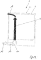
- FIG. 1 The embodiment of the invention is shown in a schematic representation in Figure 1 shown. How to compare the Figures 1 and 13 results, it is provided according to the invention that part of the cooling air flow 18 is circulated in a bypass flow 20 and is thereby guided past the washing container 3 on the outside.
- this method implementation is achieved in that the intake manifold 17 does not abut the recess 16 provided by the base panel 15, but rather is provided that the intake manifold 17 with its end face 23 facing the base panel 15 and providing an intake opening 27, leaving a gap 28 is arranged at a distance from the base panel 15, as is shown in particular in FIG Figure 6 reveals.
- the arrangement of the base panel 15 and the intake socket 17, which is spaced apart according to the invention, contributes to the fact that air previously drawn in as ambient air 19 by the blower 10 can be guided past the washing container 3 in the circulating mode, in that process air surrounding the washing container 3 is sucked in again and via the gap between the base panel and the intake connector can come to the air in the washing container again.
- a mixture of newly drawn in ambient air 19 and process air 26 carried out in the circulating mode takes place.
- the result of this method implementation is that the part 18 of the cooling air flow 8, which is guided along a section of the underside of a worktop arranged above the washing compartment 3, has a higher temperature than that in the cooling air flow 8 according to the state of the art Case is.
- the bypass guide according to the invention therefore leads to an increase in the temperature level in the cooling air flow 8.
- the result of the implementation of the method according to the invention is that the worktop is also heated more than in the prior art, which results in a significant reduction in the formation of condensate on the underside of the worktop.
- Another advantage of the temperature increase is that the relative air humidity within the cooling air flow discharged to the outside is reduced in contrast to the prior art, so that when a door is opened, moist air escaping from the wash cabinet 4, that is to say vapors, can be better absorbed. This also helps to minimize the formation of condensation on the underside of the worktop 7.
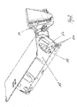
- Figure 2 shows a schematic perspective illustration of the base cover 15 covering the base 9 on the front side.
- this has a recess 16 which has a blocking in the form of individual ribs 21.
- a through opening is provided between two adjacent ribs, the total of the through openings defining the recess 16.
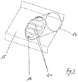
- the fan 10 is arranged is in fluidic connection with the recess 16 with the interposition of a connecting piece 17. This factual relationship can be illustrated using the schematic representation Figure 3 also recognize.
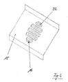
- Figure 4 shows in a schematic representation the recess 16 in the base panel 15 in detail.
- the cross-sectional area 22 provided overall by the recess 16 is shown hatched.
- Figure 5 shows the plinth-side end face 23 of the intake connector 17.
- the intake opening 27 provided on the front side by the intake connector 17 can be seen, the cross-sectional area 24 provided by the intake opening 27 being shown hatched.
- Figure 6 can be seen in a schematic side view of the spaced arrangement of intake manifold 17 and base panel 15, wherein a gap 28 is provided between the base panel 15 and the end face 23 of the intake manifold 17.
- the gap dimension X structurally defines the admixture ratio of circulated process air to aspirated ambient air.
- the proportion of circulated process air is preferably between 25% and 75%, which means that the proportion of ambient air is preferably between 75% and 25%.
- the cutout 16 in the orifice 15 is equipped with air guide elements 25 on the intake port side.
- This can be, for example, an annular configuration which surrounds the recess 16 all around.
- Figure 11 an embodiment with a recess 16, which has an annular air guiding element 25 on the outlet connection side.
- Figure 10 shows a recess 16 having a plurality of openings, each opening being equipped with a respective air guiding element 25 on the intake port side, as is also the case in FIG Figure 6 shown embodiment shows.
- FIG. 7 and 8 still different embodiments of the design of the recess 16 can be seen. It shows Figure 7 a simple recess 16 in the form of an opening.
- FIG. 18 shows an embodiment according to which the cutout 16 is blocked by a ribbing 21.
- This ribbing 21 has the advantage that it can serve as a support for safety devices for the blower 10, such as for screening devices or the like.
Landscapes
- Washing And Drying Of Tableware (AREA)
Abstract
Description
- Die Erfindung betrifft ein Verfahren zur Durchführung eines Trocknungs-Programmabschnitts in einer Geschirrspülmaschine, insbesondere eine Haushaltsgeschirrspülmaschine, mit einem Spülbehälter, der zur Beschickung mit zu reinigendem Spülgut auf seiner Frontseite eine Beschickungsöffnung aufweist, die mittels einer verschwenkbar gelagerten Spülraumtür fluiddicht verschließbar ist, sowie mit einer Kondensations-Trocknungseinrichtung, die Mittel zur Erzeugung eines Kühlluftstroms aufweist, wobei ein Teil des Kühlluftstroms entlang eines Abschnitts der Unterseite einer oberhalb des Spülbehälters angeordneten Arbeitsplatte geleitet wird.
- Ein gattungsgemäßes Verfahren sowie eine Geschirrspülmaschine zur Durchführung eines gattungsgemäßen Verfahrens sind aus der
DE 10 2007 008 950 B4 bekannt. - Die aus der
DE 10 2007 008 950 B4 vorbekannte Geschirrspülmaschine verfügt über einen Spülbehälter, der seinerseits einen Spülraum zur Aufnahme von zu reinigendem Spülgut bereitstellt. Zwecks Beschickung des Spülraums mit zu reinigendem Spülgut ist eine spülbehälterseitige Beschickungsöffnung vorgesehen, die mittels einer verschwenkbar ausgebildeten Spülraumtür fluiddicht verschließbar ist. - Zwecks Trocknung von bestimmungsgemäß gereinigtem Spülgut verfügt die Geschirrspülmaschine desweiteren über eine Kondensations-Trocknungseinrichtung, die in Form eines Gebläses Mittel zur Erzeugung eines Kühlluftstroms aufweist. Gemäß dieser vorbekannten Konstruktion wird im Anschluss an einen wasserführenden Programmabschnitt zur Trocknung von Spülgut Kühlluft durch das Gebläse angesaugt und an den Seitenflächen des Spülbehälters vorbeigeführt. Infolge dessen kommt es zu einer Abkühlung der Seitenwände des Spülbehälters, was wiederum dazu führt, dass die Feuchtigkeit aus der im Inneren des Spülbehälters befindlichen Prozessluft auskondensiert. Das so entstehende Kondensat sammelt sich im unteren Bereich des Spülbehälters an, von wo aus es abgepumpt werden kann.
- In der Praxis kommt es nicht selten vor, dass die Beschickungsöffnung durch verwenderseitige Verschwenkung der Spülraumtür oder programmgemäß automatisch vor einem ordnungsgemäßen Abschluss der Spülguttrocknung geöffnet wird. Es tritt dann die im Spülbehälter befindliche Prozessluft durch die geöffnete Beschickungsöffnung aus, was in nachteiliger Weise zu einer Kondensatbildung an der Unterseite einer oberhalb des Spülbehälters angeordneten Arbeitsplatte führen kann.
- Um diesem Nachteil zu begegnen, ist es aus der
DE 10 2007 008 940 B4 bekannt, ein Teil des Kühlluftstroms entlang eines Abschnitts der Unterseite einer oberhalb der Spülraumtür angeordneten Arbeitsplatte zu leiten. Diese Maßnahme führt in vorteilhafter Weise zu einer Erwärmung der Arbeitsplatte, was eine Minimierung der Kondensatbildung erbringt. Dabei kann der außenseitig am Spülbehälter vorbeigeführte und dadurch erwärmte Kühlluftstrom sowohl vor als auch nach einem spaltweisen Öffnen der Spülraumtür zumindest teilweise an der Arbeitsplattenunterseite vorbeigeführt werden. - Obgleich sich die aus der
DE 10 2007 008 950 B4 vorbekannte Verfahrensdurchführung im alltäglichen Praxiseinsatz bewährt hat, besteht Verbesserungsbedarf. Es ist insbesondere angestrebt, eine noch effektivere Verfahrensabwicklung zu erzielen, und dies weitestgehend unabhängig von möglichen Einbausituationen. - Es ist deshalb die Aufgabe der Erfindung, ein gattungsgemäßes Verfahren dahingehend weiter zu entwickeln, dass eine von der Einbausituation weitestgehend unabhängige Vermeidung von unerwünschter Kondensatbildung an den die Geschirrspülmaschine umgebenden Küchenmöbeln sichergestellt ist.
- Zur Lösung dieser Aufgabe wird mit der Erfindung vorgeschlagen, ein Verfahren der gattungsgemäßen Art, das sich dadurch auszeichnet, dass ein Teil des Kühlluftstroms in einen Bypassstrom umgewälzt und dabei außenseitig des Spülbehälters an diesem vorbeigeführt wird.
- Erfindungsgemäß wird ein Teil des erzeugten Kühlluftstroms im Bypassstrom umgewälzt. Ein Teil der außenseitig am Spülbehälter vorbeigeführten Prozessluft befindet sich damit in einem permanenten Umluftbetrieb. Dies führt dazu, dass sich das Temperaturniveau der außenseitig am Spülbehälter vorbeigeführten Prozessluft erhöht, und zwar je nach Anwendungsfall um beispielsweise 2 bis 5 Kelvin. Damit erhöht sich im Unterschied zum Stand der Technik auch die Temperatur des Teils des Kühlluftstroms, der entlang eines Abschnitts der Unterseite einer oberhalb des Spülbehälters angeordneten Arbeitsplatte geleitet wird, womit sich die Oberflächentemperatur der Arbeitsplattenunterseite ebenfalls entsprechend erhöht. Dies führt zu dem positiven Effekt einer noch weitergehenden Reduzierung des Kondensatrisikos an der Arbeitsplattenunterseite.
- Aufgrund der Temperaturerhöhung reduziert sich zudem die relative Feuchte der ausgetriebenen Luft, das heißt des Teils des Kühlluftstroms, der unterseitig der Arbeitsplatte entlanggeführt wird. Im Ergebnis kann die ausgetriebene Luft die nach einer Türöffnung ausströmenden Wrasen besser aufnehmen, was ebenfalls zur Minimierung einer Kondensatbildung an der Arbeitsplattenunterseite und an benachbarten Möbelfronten beiträgt.
- Aufgrund der erhöhten Temperatur des vom Gebläse des Kondensations-Trocknungseinrichtung abgegebenen Kühlluftstroms kommt es zwar zu einer verringerten Abkühlgeschwindigkeit des Spülbehälters und dessen Beladung, doch dieser Nachteil wird durch den unabhängig von der Einbausituation hohen Volumenstroms und der verbesserten Vorwärmung und Feuchtigkeitsaufnahmefähigkeit mehr als kompensiert. Und so überwiegt insgesamt der positive Effekt. Denn die Kondensatbildung kann deutlich reduziert werden, und zwar sowohl an einer oberhalb des Spülbehälters angeordneten Arbeitsplatte als auch an zur Geschirrspülmaschine benachbarten Möbeln. Nach Versuchen der Anmelderin wird ein optimiertes Ergebnis erreicht, wenn der Anteil an umgewälzter Prozessluft zwischen 25 % und 75 % bei einem Fördervolumen zwischen 25 m3/h und 65 m3/h liegt.
- Im Ergebnis der erfindungsgemäßen Verfahrensdurchführung steht eine Temperaturerhöhung der außenseitig am Spülbehälter vorbeigeführten Prozessluft durch einen teilweisen Umwälzbetrieb. Dies führt im Vergleich zum Stand der Technik zu einer Erhöhung der Prozesslufttemperatur, so dass zur Geschirrspülmaschine benachbarte Möbel und/oder eine oberhalb der Geschirrspülmaschine angeordnete Arbeitsplatte auf ein im Vergleich zum Stand der Technik höheres Aufwärmniveau gebracht werden können, was dann im Ergebnis eine verminderte Kondensatbildung erbringt.
- Der Kühlluftstrom ergibt sich gemäß einem weiteren Merkmal der Erfindung als Mischung aus Umgebungsluft einerseits und außenseitig des Spülbehälters im Bypassstrom vorbeigeführter Prozessluft andererseits. Dabei kann der Anteil der umgewälzten Prozessluft beispielsweise zwischen 25 % und 75 % betragen. Dabei stellt sich ein umso höheres Temperaturniveau ein, je höher der Anteil an umgewälzter Prozessluft im Kühlluftstrom ist.
- Das Mittel zur Erzeugung eines Kühlluftstroms ist gemäß einem weiteren Merkmal der Erfindung ein Gebläse, das anteilig Umgebungsluft einerseits und Prozessluft andererseits ansaugt. In Abkehr zum Stand der Technik wird durch das Gebläse mithin nicht nur Umgebungsluft angesaugt, sondern auch im Umwälzbetrieb geführte Prozessluft, so dass sich im Ergebnis ein Kühlluftstrom aus einer Mischung aus angesaugter Umgebungsluft und Prozessluft einstellt. Dabei führt die Beimischung von umgewälzter Prozessluft zum Kühlluftstrom zur schon vorbeschriebenen Steigerung des Temperaturniveaus des Kühlluftstroms.
- Vorrichtungsseitig wird mit der Erfindung desweiteren vorgeschlagen eine Geschirrspülmaschine insbesondere zur Durchführung des vorbeschriebenen Verfahrens, mit einem Spülbehälter, der zur Beschickung mit zu reinigendem Spülgut auf seiner Frontseite eine Beschickungsöffnung aufweist, die mittels einer verschwenkbar gelagerten Spülraumtür fluiddicht verschließbar ist, sowie mit einer Kondensations-Trocknungseinrichtung, die Mittel zur Erzeugung eines Kühlluftstroms aufweist, wobei das Mittel zur Erzeugung des Kühlluftstroms ein Gebläse ist, das in einem Sockel unterhalb des Spülbehälters angeordnet ist, wobei der Sockel zur Ansaugung von Umgebungsluft durch das Gebläse eine in einer frontseitigen Sockelblende ausgebildete Aussparung aufweist, an die das Gebläse mittels eines Ansaugstutzens strömungstechnisch angeschlossen ist, wobei der Ansaugstutzen mit seiner der Sockelblende zugewandten und einer Ansaugöffnung bereitstellenden Stirnseite unter Belassung eines Spaltraums beanstandet zur Sockelblende angeordnet ist.
- Die erfindungsgemäße Geschirrspülmaschine verfügt über ein aus dem Stand der Technik an sich bekanntes Gebläse zur Ansaugung von Umgebungsluft, die austrittsseitg des Gebläses über die Außenwände des Spülbehälters geführt wird. Das Gebläse ist in einem Sockel der Geschirrspülmaschine unterhalb des Spülbehälters angeordnet. In einer frontseitigen Sockelblende des Sockels ist eine Aussparung ausgebildet, an die das Gebläse mittels eines Ansaugstutzens strömungstechnisch angeschlossen ist. Damit kann im bestimmungsgemäßen Betriebsfall über die Aussparung in der Sockelblende durch das Gebläse Außenluft angesaugt und außenseitig über den Spülbehälter geführt werden. Erfindungsgemäß ist nun vorgesehen, dass der Ansaugstutzen des Gebläses mit seiner der Sockelblende zugewandten und eine Ansaugöffnung bereitstellenden Stirnseite nicht luftdicht an die in der Sockelblende ausgebildete Aussparung angeschlossen ist, sondern vielmehr unter Belassung eines Spaltraums beabstandet zur Sockelblende angeordnet ist. Damit ergibt sich ein umlaufender Spaltraum zwischen der der Sockelblende zugewandten Stirnseite des Ansaugstutzens und der Sockelblende, durch den hindurch den Spülbehälter umspülende Prozessluft angesaugt und im Umwälzbetrieb geführt werden kann. Die beabstandete Anordnung von Sockelblende und Ansaugstutzen sorgt mithin dafür, dass im bestimmungsgemäßen Betriebsfall nicht nur Umegebungsluft angesaugt wird, sondern auch Prozessluft, womit eine Durchmischung von Umgebungsluft mit schon vorerwärmter Prozessluft stattfindet. Im Ergebnis dieser konstruktiven Ausgestaltung wird vom Gebläse ein Kühlluftstrom abgegeben, der auf einem höheren Temperaturniveau als nach dem Stand der Technik liegt, demgemäß ausschließlich Umgebungsluft angesaugt wird. Diese Ausgestaltung erbringt die schon vorstehend erläuterten Vorteile.
- Es ist gemäß einem weiteren Merkmal der Erfindung vorgesehen, dass die Querschnittsfläche der Ansaugöffnung des Ansaugstutzens und die Querschnittsfläche der Aussparung in der Sockelblende parallel zueinander verlaufend ausgerichtet sind. Damit wird eine gleichmäßige und über den umlaufenden Spaltraum homogen verteilte Ansaugung von Prozessluft erreicht, so dass eine optimierte Vermischung von neu angesaugter Umgebungsluft und im Umwälzbetrieb geführter Prozessluft erreicht ist.
- Die Querschnittsflächen von Ansaugöffnung und Aussparung sind in Abhängigkeit des Spaltmasses zwischen Stirnseite des Anschlussstutzens und Sockelblende auszulegen. Alternativ ergibt sich das Spaltmaß in Abhängigkeit der gegebenen Querschnittsfläche. Dabei ist bevorzugt, dass sich das Spaltmaß in Abhängigkeit des Verhältnisses von Querschnittsfläche der Aussparung in der Sockelblende zu Querschnittsfläche der Ansaugöffnung des Ansaugstutzens ergibt, und zwar als

- Als Spaltmaß zwischen Sockelblende und Stirnseite des Ansaugstutzens kommen beispielsweise zwischen 4 mm und 12 mm, vorzugsweise zwischen 6 mm und 10 mm, noch mehr bevorzugt zwischen 7 mm und 9 mm in Frage. Die Querschnittsflächen von Ansaugstutzen und Aussparung können jeweils zwischen 20 cm2 und 70 cm2, vorzugsweise zwischen 30 cm2 und 60 cm2, noch mehr bevorzugt zwischen 40 cm2 und 50 cm2 betragen.
- Gemäß einem weiteren Merkmal der Erfindung ist vorgesehen, dass die Querschnittsfläche der Aussparung in der Sockelblende verblockt ist. Durch eine solche Verblockung ist eine Reduzierung der Querschnittsfläche erreicht, womit konstruktiv Einfluss auf das Spaltmaß zwischen der Stirnseite des Anschlussstutzens und der Sockelblende genommen werden kann. Dabei kann die Verblockung, das heißt die Reduktion der Querschnittsfläche der Aussparung in der Sockelblende durch unterschiedliche konstruktive Umsetzungen realisiert sein. In der einfachsten Ausgestaltung erfolgt eine Reduzierung des Durchmessers der Aussparung. Alternativ kann eine Verrippung vorgesehen sein, dergemäß eine Aussparung mit einer Mehrzahl von Durchtrittsöffnungen entsteht, die jeweils durch eine Rippe voneinander getrennt sind. Von Vorteil einer solchen Verrippung ist, dass eine Trageinrichtung für eine Schutzvorrichtung für das Gebläse gegeben ist, beispielsweise zur Aufnahme und Abstützung eines Siebs.
- Es ist gemäß einem weiteren Merkmal der Erfindung vorgesehen, dass die von der Sockelblende bereitgestellte Aussparung ansaugstutzenseitig mit einem Luftleitelement ausgerüstet ist. Bei einem solchen Luftleitelement kann es sich beispielsweise um einen die Aussparung ansaugstutzenseitig umgebenden Ring handeln. Ein solches Luftleitelement begünstigt die Zuströmung des Bypassstromes.
- Die erfindungsgemäße Ausgestaltung erbringt im Ergebnis eine Reihe von Vorteilen. Zum einen ist die erfindungsgemäße Ausgestaltung deutlich robuster gegenüber Einbausituationen, d.h. die jeweils vorliegende Einbausituation hat allenfalls einen marginalen Einfluss auf die Funktion des Wrasenschutzes. Denn die Rückführung von bereits vorgewärmter Prozessluft bewirkt in jedem Fall, dass das vom Gebläse umgesetzte Volumen nicht zu stark einbrechen kann und führt unabhängig von der Einbausituation vor Ort dazu, dass es zu einer Erhöhung der Temperatur im Prozessluftstrom kommt, und dies mit der Folge, dass eine verbesserte Erwärmung einer oberhalb der Geschirrspülmaschine angeordneten Arbeitsplatte und/oder zur Geschirrspülmaschine benachbarten Möbeln mit der Folge erreicht ist, dass das Kondensatrisiko minimiert ist. Es wird somit ein ggf. geringerer Frischluftanteil durch eine Erhöhung der Temperatur der Austrittsluft kompensiert. Auch bei einer Einbausituation mit stark Verblockung, etwa bei einem Hochschrankeinbau, ist dadurch ein hinreichender Wrasenschutz sichergestellt.
- Die bewusst auf Beabstandung zwischen Sockelblende und Ansaugstutzen ausgelegte Konstruktion macht die nach dem Stand der Technik bislang noch erforderliche Abdichtung beispielsweise durch einen Faltenbalg zwischen der Aussparung in der Sockelblende und dem Ansaugstutzen überflüssig. Dadurch sind die Material- und Montagekosten reduziert.
- Darüber hinaus ist es möglich, aufgrund der zumindest teilweisen Rückführung von Prozessluft im Umwälzbetrieb ein Gebläse mit verringerter Motorleistung einsetzen zu können. Auch dies trägt zur Kostenreduzierung bei.
- Schlussendlich wird im Unterschied zum Stand der Technik ein nicht so volumenstarkes Gebläse benötigt, was es gestattet, die Gebläsegröße zu reduzieren, was zu einem verringerten Bauraum führt.
- Nicht zuletzt ist die nach außen abgegebene Prozessluft in der Feuchtigkeitsaufnahmemöglichkeit maximiert, so dass aus einer geöffneten Beschickungsöffnung austretende Wrasen besser aufgenommen, das heißt durch die Prozessluft verdünnt werden können.
- Weitere Merkmale und Vorteile der Erfindung ergeben sich aus der nachfolgenden Beschreibung anhand der Figuren. Dabei zeigen:
- Fig. 1
- Darstellung einer erfindungsgemäßen Geschirrspülmaschine,
- Fig. 2
- in schematischer Perspektivdarstellung ausschnittsweise eine Sockelblende;
- Fig. 3
- in schematischer Perspektivdarstellung eine in einer Sockelblende ausgebildete Aussparung gemäß einer ersten Ausführungsform;
- Fig. 4
- die Darstellung nach
Figur 3 mit eingezeichneter Querschnittsfläche; - Fig. 5
- in schematischer Perspektivdarstellung die sockelblendenseitige Stirnseite eines Ansaugstutzens;
- Fig. 6
- in schematischer Darstellung in Seitenansicht die beabstandete Anordnung von Ansaugstutzen und Sockelblende
- Fig. 7
- in schematisch perspektivischer Darstellung die in einer Sockelblende ausgebildete Aussparung gemäß einer zweiten Ausführungsform;
- Fig. 8
- schematisch perspektivischer Darstellung die in einer Sockelblende ausgebildete Aussparung gemäß einer dritten Ausführungsform;
- Fig. 9
- in schematischer Seitenansicht eine Sockelblende gemäß einer ersten Ausführungsform
- Fig. 10
- in schematischer Seitenansicht eine Sockelblende gemäß einer zweiten Ausführungsform;
- Fig. 11
- in schematischer Seitenansicht eine Sockelblende gemäß einer dritten Ausführungsform;
- Fig. 12
- in schematischer Seitenansicht eine Geschirrspülmaschine nach dem Stand der Technik;
- Fig. 13
- in einer Schemadarstellung die Geschirrspülmaschine nach
Figur 12 . -
Figur 12 lässt in rein schematischer Seitenansicht eine Geschirrspülmaschine 1 nach dem Stand der Technik erkennen. - Die Geschirrspülmaschine 1 verfügt über ein Gehäuse 2, das einen Spülbehälter 3 aufnimmt. Der Spülbehälter 3 stellt seinerseits einen Spülraum 4 zur Aufnahme von zu reinigendem Spülgut bereit. Für eine verwenderseitige Beschickung des Spülbehälters 3 mit zu reinigendem Spülgut dient eine Beschickungsöffnung 5, die mittels einer Spülraumtür 6 fluiddicht verschließbar ist. Dabei ist die Spülraumtür 6 um eine horizontal verlaufende Drehachse 29 verschwenkbar gelagert.
- Die Geschirrspülmaschine 1 verfügt desweiteren über einen in Höhenrichtung unterhalb des Spülbehälters 3 angeordneten Sockel 9. Frontseitig schließt der Sockel 9 mit einer Sockelblende 15 ab. Der Sockel 9 beherbergt eine Kondensations-Trocknungseinrichtung 14. Diese verfügt in Form eines Gebläses 10 über Mittel zur Erzeugung eines Kühlluftstroms 8. Dabei weist das Gebläse 10 ein in einem Gehäuse 11 angeordnetes Gebläserad 12 auf, das im bestimmungsgemäßen Betriebsfall mittels eines Motors 13 angetrieben wird.
- Das Gebläse 10 ist mittels eines Ansaugstutzens 17 an eine in der Sockelblende 15 ausgebildete Aussparung 16 strömungstechnisch angeschlossen. Im bestimmungsgemäßen Betriebsfall wird durch das Gebläse 10 Umgebungsluft durch die Aussparung 16 in der Sockelblende 15 hindurch angesogen, die dann durch den Ansaugstutzen 17 zur Ausgangsseite des Gehäuses 10 zur Ausbildung des Kühlluftstroms 8 gefördert wird.
-
Figur 13 lässt die Ausgestaltung nach dem Stand der Technik in einer weiteren SchemaDarstellung erkennen. Wie sich aus dieser Darstellung ergibt, wird die Umgebungsluft 19 unter Zwischenordnung des Ansaugstutzens 17 vom Gebläse 10 angesaugt, wobei das Gebläse 10 einen außenseitig auf den Spülbehälter 3 aufgegebenen Kühlluftstrom 8 abgibt. Ein Teil 18 des Kühlluftstroms 8 wird entlang eines Abschnitts der Unterseite einer oberhalb des Spülbehälters 3 angeordneten Arbeitsplatte 7 geleitet. Infolge dessen erwärmt sich die Arbeitsplatte unterseitig, was zu einer verminderten Kondensatbildung an der Arbeitsplatte führt, wenn infolge einer Spülraumtüröffnung Wrasen aus dem Spülraum 4 austreten. - Die erfindungsgemäße Ausgestaltung ist in schematischer Darstellung in
Figur 1 dargestellt. Wie sich bei einem Vergleich derFiguren 1 und13 ergibt, ist erfindungsgemäß vorgesehen, dass ein Teil des Kühlluftstroms 18 in einem Bypassstrom 20 umgewälzt und dabei außenseitig des Spülbehälters 3 an diesem vorbeigeführt wird. Konstruktiv wird diese Verfahrensdurchführung dadurch erreicht, dass der Ansaugstutzen 17 nicht dicht an der von der Sockelblende 15 bereitgestellten Aussparung 16 anliegt, sondern vielmehr vorgesehen ist, dass der Ansaugstutzen 17 mit seiner der Sockelblende 15 zugewandten und einer Ansaugöffnung 27 bereitstellenden Stirnseite 23 unter Belassung eines Spaltraums 28 beabstandet zur Sockelblende 15 angeordnet ist, wie dies insbesondere auch die Darstellung nachFigur 6 erkennen lässt. - Die erfindungsgemäß beabstandete Anordnung von Sockelblende 15 und Ansaugstutzen 17 trägt dazu bei, dass zuvor als Umgebungsluft 19 durch das Gebläse 10 angesaugte Luft im Umwälzbetrieb am Spülbehälter 3 vorbeigeführt werden kann, indem den Spülbehälter 3 umgebende Prozessluft erneut angesogen und über den Spaltraum zwischen Sockelblende und Ansaugstutzen zur erneuten Luftbeaufschlagung des Spülbehälters gelangen kann. Es findet insofern gemäß der erfindungsgemäßen Ausgestaltung eine Vermischung von neu angesogener Umgebungsluft 19 und im Umwälzbetrieb geführter Prozessluft 26 statt.
- Im Ergebnis dieser Verfahrensdurchführung steht, dass der Teil 18 des Kühlluftstroms 8, der entlang eines Abschnitts der Unterseite einer oberhalb des Spülbehälters 3 angeordneten Arbeitsplatte geführt wird, eine höhere Temperatur aufweist, als dies bei dem Kühlluftstrom 8 nach der Ausbildung gemäß dem Stand der Technik der Fall ist. Die erfindungsgemäße Bypassführung führt mithin zu einer Anhebung des Temperaturniveaus im Kühlluftstrom 8.
- Im Ergebnis der erfindungsgemäßen Verfahrensdurchführung steht, dass auch die Arbeitsplatte stärker als nach dem Stand der Technik erwärmt wird, was eine deutliche Reduzierung der Kondensatbildung an der Unterseite der Arbeitsplatte zur Folge hat.
- Von Vorteil der Temperaturerhöhung ist zudem, dass die relative Luftfeuchte innerhalb des nach außen abgegebenen Kühlluftstroms im Unterschied zum Stand der Technik verringert ist, so dass im Falle einer Türöffnung aus dem Spülraum 4 austretende feuchte Luft, das heißt Wrasen besser aufgenommen werden können. Auch dies trägt zu einer Minimierung der Kondensatbildung an der Unterseite der Arbeitsplatte 7.
- Die weiteren
Figuren 2 bis 11 lassen konstruktive Ausführungen der erfindungsgemäßen Ausgestaltung im Detail erkennen. -
Figur 2 zeigt in schematischer Perspektivdarstellung die den Sockel 9 frontseitig abdeckende Sockelblende 15. Diese verfügt im gezeigten Ausführungsbeispiel über eine Aussparung 16, die eine Verblockung in Form einzelner Rippen 21 aufweist. Dabei ist zwischen zwei benachbarten Rippen jeweils eine Durchgangsöffnung vorgesehen, wobei die Durchgangsöffnungen in ihrer Summe die Aussparung 16 definieren. In Durchströmungsrichtung hinter der Sockelblende 15 ist das Gebläse 10 angeordnet, das mit der Aussparung 16 unter Zwischenordnung eines Anschlussstutzens 17 in strömungstechnischer Verbindung steht. Dieser Sachzusammenhang lässt sich anhand der schematischen Darstellung nachFigur 3 ebenfalls erkennen. -
Figur 4 lässt in schematischer Darstellung die Aussparung 16 in der Sockelblende 15 im Detail erkennen. Dabei ist die insgesamt von der Aussparung 16 bereitgestellte Querschnittsfläche 22 schraffiert dargestellt. -
Figur 5 zeigt die sockelblendenseitige Stirnseite 23 des Ansaugstutzens 17. Es ist die vom Ansaugstutzen 17 stirnseitig bereitgestellte Ansaugöffnung 27 zu erkennen, wobei die von der Ansaugöffnung 27 bereitgestellte Querschnittsfläche 24 schraffiert dargestellt ist. -
Figur 6 lässt in schematischer Seitenansicht die beabstandete Anordnung von Ansaugstutzen 17 und Sockelblende 15 erkennen, wobei ein Spaltraum 28 zwischen Sockelblende 15 und der Stirnseite 23 des Ansaugstutzens 17 vorgesehen ist. - Das Spaltmaß X legt konstruktiv das Beimischungsverhältnis von umgewälzter Prozessluft zu angesogener Umgebungsluft fest. Dabei beträgt der Anteil an umgewälzter Prozessluft vorzugsweise zwischen 25 % und 75 %, womit der Anteil der Umgebungsluft bevorzugterweise zwischen 75 % und 25 % liegt.
- Konstruktiv ergibt sich das Spaltmaß X in Abhängigkeit der Querschnittsflächen 22 und 24, und zwar nach der Formel

- Zur Begünstigung der Zuströmung des Bypassstromes 20 ist die Aussparung 16 in der Blende 15 ansaugstutzenseitig mit Luftleitelementen 25 ausgerüstet. Dabei kann es sich beispielsweise um eine ringförmige Ausgestaltung handeln, die die Aussparung 16 umlaufend umgibt.
- Die
Figuren 9, 10 und 11 lassen in diesem Zusammenhang unterschiedliche Ausführungsformen erkennen. Dabei zeigtFigur 9 eine Aussparung 16 ohne ansaugstutzenseitige Luftleitelemente 25. - Im Unterschied zur Ausgestaltung nach
Figur 9 zeigtFigur 11 eine Ausführungsform mit einer Aussparung 16, die ausgangsstutzenseitig ein ringförmig ausgebildetes Luftleitelement 25 aufweist.Figur 10 zeigt eine mehrere Durchbrüche aufweisende Aussparung 16, wobei jeder Durchbruch ansaugstutzenseitig mit einem jeweiligen Luftleitelement 25 ausgerüstet ist, so wie dies auch die inFigur 6 dargestellte Ausführungsform zeigt. - Die
Figuren 7 und 8 lassen noch unterschiedliche Ausführungsformen der Ausgestaltung der Aussparung 16 erkennen. Dabei zeigtFigur 7 eine einfache Aussparung 16 in der Ausgestaltung eines Durchbruchs. Figur 18 zeigt eine Ausführungsform, dergemäß eine Verblockung der Aussparung 16 durch eine Verrippung 21 gegeben ist. Diese Verrippung 21 hat den Vorteil, dass sie als Abstützung für Sicherheitsvorrichtungen für das Gebläse 10 dienen kann, wie beispielsweise für Siebeinrichtungen oder dergleichen.Bezugszeichen 1 Geschirrspülmaschine 18 Teil des Kühlluftstroms 2 Gehäuse 19 Umgebungsluft 3 Spülbehälter 20 Bypassstrom 4 Spülraum 21 Rippe 5 Beschickungsöffnung 22 Querschnittsfläche 6 Spülraumtür 23 Stirnseite 7 Arbeitsplatte 24 Querschnittsfläche 8 Kühlluftstrom 25 Luftleitelement 9 Sockel 26 Prozessluft 10 Gebläse 27 Ansaugöffnung 11 Gehäuse 28 Spaltraum 12 Gebläserad 29 Drehachse 13 Motor X Spaltmaß 14 Kondensations-Trocknungseinrichtung 15 Sockelblende 16 Aussparung 17 Ansaugstutzen
Claims (13)
- Verfahren zur Durchführung eines Trocknungs-Programmabschnitts in einer Geschirrspülmaschine (1), insbesondere Haushaltsgeschirrspülmaschine, mit einem Spülbehälter (3), der zur Beschickung mit zu reinigendem Spülgut auf seiner Frontseite eine Beschickungsöffnung (5) aufweist, die mittels einer verschwenkbar gelagerten Spülraumtür (6) fluiddicht verschließbar ist, sowie mit einer Kondensations-Trocknungseinrichtung (14), die Mittel (10) zur Erzeugung eines Kühlluftstroms (8) aufweist, wobei ein Teil (18) des Kühlluftstroms (8) entlang eines Abschnitts der Unterseite einer oberhalb des Spülbehälters (3) angeordneten Arbeitsplatte (7) geleitet wird, dadurch gekennzeichnet, dass ein Teil des Kühlluftstroms (8) in einem Bypassstrom (20) umgewälzt und dabei außenseitig des Spülbehälters (3) an diesem vorbeigeführt wird.
- Verfahren nach Anspruch 1, dadurch gekennzeichnet, dass sich der Kühlluftstrom (8) als Mischung aus Umgebungsluft (19) und außenseitig des Spülbehälters (3) im Bypassstrom (20) vorbeigeführter Prozessluft (26) ergibt.
- Verfahren nach Anspruch 1 oder 2, dadurch gekennzeichnet, dass das Mittel zur Erzeugung eines Kühlluftstroms (8) ein Gebläse (10) ist, das anteilig Umgebungsluft (19) einerseits und Prozessluft (26) andererseits ansaugt.
- Geschirrspülmaschine, insbesondere Haushaltsgeschirrspülmaschine, zur Durchführung des Verfahrens nach einem der vorhergehenden Ansprüche 1 bis 3, mit einem Spülbehälter (3), der zur Beschickung mit zu reinigendem Spülgut auf seiner Frontseite eine Beschickungsöffnung (5) aufweist, die mittels einer verschwenkbar gelagerten Spülraumtür (6) fluiddicht verschließbar ist, sowie mit einer Kondensations-Trocknungseinrichtung (14), die Mittel (10) zur Erzeugung eines Kühlluftstroms (8) aufweist, wobei das Mittel zur Erzeugung eines Kühlluftstroms (8) ein Gebläse (10) ist, das in einem Sockel (9) unterhalb des Spülbehälters (3) angeordnet ist, wobei der Sockel (9) zur Ansaugung von Umgebungsluft (19) durch das Gebläse (10) eine in einer frontseitigen Sockelblende (15) ausgebildete Aussparung (16) aufweist, an die das Gebläse (10) mittels eines Ansaugstutzens (17) strömungstechnisch angeschlossen ist, dadurch gekennzeichnet, dass der Ansaugstutzen (17) mit seiner der Sockelblende (15) zugewandten und eine Ansaugöffnung (27) bereitstellenden Stirnseite (23) unter Belassung eines Spaltraums (28) beabstandet zur Sockelblende (15) angeordnet ist.
- Geschirrspülmaschine nach Anspruch 4, dadurch gekennzeichnet, dass die Querschnittsfläche (24) der Ansaugöffnung (27) des Ansaugstutzens (17) und die Querschnittsfläche (22) der Aussparung (16) in der Sockelblende (15) parallel zueinander verlaufend ausgerichtet sind.
- Geschirrspülmaschine nach Anspruch 4 oder 5, dadurch gekennzeichnet, dass die Querschnittsfläche (24) der Ansaugöffnung (27) des Anschlussstutzens (17) zwischen 20 cm2 und 70 cm2, vorzugsweise zwischen 30 cm2 und 60cm2, noch mehr bevorzugt zwischen 40 cm2 und 50 cm2 beträgt.
- Geschirrspülmaschine nach einem der vorhergehenden Ansprüche 4 bis 6, dadurch gekennzeichnet, dass die Querschnittsfläche (22) der Aussparung (16) in der Sockelblende (15) zwischen 20 cm2 und 70 cm2, vorzugsweise zwischen 30 cm2 und 60 cm2, noch mehr bevorzugt zwischen 40 cm2 und 50 cm2 beträgt.
- Geschirrspülmaschine nach einem der vorhergehenden Ansprüche 4 bis 7, dadurch gekennzeichnet, dass das Spaltmaß X zwischen Sockelblende (15) und Stirnseite (23) des Ansaugstutzens (17) zwischen 4 mm und 12 mm, vorzugsweise zwischen 6 mm und 10 mm, noch mehr bevorzugt zwischen 7 mm und 9 mm beträgt.
- Geschirrspülmaschine nach einem der vorhergehenden Ansprüche 4 bis 8, dadurch gekennzeichnet, dass sich das Spaltmaß X in Abhängigkeit des Verhältnisses von Querschnittsfläche (22) der Aussparung (16) in der Sockelblende (15) zu Querschnittsfläche (24) der Ansaugöffnung (27) des Ansaugstutzens (17) ergibt, und zwar als X = Querschnittsfläche (22)/Querschnittsfläche (24) * α, wobei α zwischen 5 mm und 25 mm, vorzugsweise zwischen 12 mm und 18 mm beträgt.
- Geschirrspülmaschine nach einem der vorhergehenden Ansprüche 4 bis 9, dadurch gekennzeichnet, dass die Querschnittsfläche (22) der Aussparung (16) in der Sockelblende (15) verblockt ist.
- Geschirrspülmaschine nach Anspruch 10, dadurch gekennzeichnet, dass die Verblockung durch Rippen (21) gebildet ist.
- Geschirrspülmaschine nach einem der vorhergehenden Ansprüche 4 bis 11, dadurch gekennzeichnet, dass die von der Sockelblende (15) bereitgestellte Aussparung (16) ansaugstutzenseitig mit einem Luftleitelement (25) ausgerüstet ist.
- Geschirrspülmaschine nach Anspruch 12, dadurch gekennzeichnet, dass das Luftleitelement (25) ein die Aussparung (16) umgebender Luftleitring ist.
Applications Claiming Priority (1)
| Application Number | Priority Date | Filing Date | Title |
|---|---|---|---|
| DE102018117552 | 2018-07-20 |
Publications (2)
| Publication Number | Publication Date |
|---|---|
| EP3597096A1 true EP3597096A1 (de) | 2020-01-22 |
| EP3597096B1 EP3597096B1 (de) | 2023-06-28 |
Family
ID=67137782
Family Applications (1)
| Application Number | Title | Priority Date | Filing Date |
|---|---|---|---|
| EP19183519.8A Active EP3597096B1 (de) | 2018-07-20 | 2019-07-01 | Verfahren zur durchführung eines trocknungs-programmabschnitts in einer geschirrspülmaschine und geschirrspülmaschine zur durchführung des verfahrens |
Country Status (1)
| Country | Link |
|---|---|
| EP (1) | EP3597096B1 (de) |
Citations (7)
| Publication number | Priority date | Publication date | Assignee | Title |
|---|---|---|---|---|
| EP0536621A1 (de) * | 1991-10-09 | 1993-04-14 | Bauknecht Hausgeräte GmbH | Geschirrspülmaschine |
| GB2263969A (en) * | 1992-02-05 | 1993-08-11 | Toshiba Kk | Drying utensils |
| EP1825800A2 (de) * | 2006-02-22 | 2007-08-29 | V-Zug AG | Geschirrspüler mit Mitteln zum Abziehen von Feuchte aus dem Bottich |
| DE102007008940A1 (de) | 2006-03-08 | 2007-09-20 | Basf Ag | Substituierte Imidazolopyrimidine, Verfahren zu ihrer Herstellung und ihre Verwendung zur Bekämpfung von Schadpilzen sowie sie enthaltende Mittel |
| DE102007008950B4 (de) | 2007-02-21 | 2011-01-05 | Miele & Cie. Kg | Verfahren zur Durchführung eines Trocknungs-Programmabschnitts in einer Spülmaschine mit einer Kondensations-Trocknungseinrichtung |
| EP2371258A2 (de) * | 2011-06-06 | 2011-10-05 | V-Zug AG | Geschirrspüler mit Türspaltlüftung |
| EP2423376A1 (de) * | 2010-08-25 | 2012-02-29 | Electrolux Home Products Corporation N.V. | Wäschebehandlungsmaschine |
-
2019
- 2019-07-01 EP EP19183519.8A patent/EP3597096B1/de active Active
Patent Citations (7)
| Publication number | Priority date | Publication date | Assignee | Title |
|---|---|---|---|---|
| EP0536621A1 (de) * | 1991-10-09 | 1993-04-14 | Bauknecht Hausgeräte GmbH | Geschirrspülmaschine |
| GB2263969A (en) * | 1992-02-05 | 1993-08-11 | Toshiba Kk | Drying utensils |
| EP1825800A2 (de) * | 2006-02-22 | 2007-08-29 | V-Zug AG | Geschirrspüler mit Mitteln zum Abziehen von Feuchte aus dem Bottich |
| DE102007008940A1 (de) | 2006-03-08 | 2007-09-20 | Basf Ag | Substituierte Imidazolopyrimidine, Verfahren zu ihrer Herstellung und ihre Verwendung zur Bekämpfung von Schadpilzen sowie sie enthaltende Mittel |
| DE102007008950B4 (de) | 2007-02-21 | 2011-01-05 | Miele & Cie. Kg | Verfahren zur Durchführung eines Trocknungs-Programmabschnitts in einer Spülmaschine mit einer Kondensations-Trocknungseinrichtung |
| EP2423376A1 (de) * | 2010-08-25 | 2012-02-29 | Electrolux Home Products Corporation N.V. | Wäschebehandlungsmaschine |
| EP2371258A2 (de) * | 2011-06-06 | 2011-10-05 | V-Zug AG | Geschirrspüler mit Türspaltlüftung |
Also Published As
| Publication number | Publication date |
|---|---|
| EP3597096B1 (de) | 2023-06-28 |
Similar Documents
| Publication | Publication Date | Title |
|---|---|---|
| DE102007019298B4 (de) | Geschirrspüler | |
| DE102012105902A1 (de) | Geschirrspülmaschine und Verfahren zum Betreiben einer Geschirrspülmaschine | |
| EP2095025A2 (de) | Dunstabsaugeinrichtung | |
| WO2017029138A1 (de) | Filtereinheit für dunstabzugsvorrichtung und kombinationsgerät mit kochfeld und dunstabzugsvorrichtung mit filtereinheit | |
| WO2017029128A1 (de) | Kombinationsgerät mit kochfeld und dunstabzugsvorrichtung | |
| WO2017029134A1 (de) | Kombinationsgerät mit kochfeld und dunstabzugsvorrichtung | |
| DE102014224459A1 (de) | Geschirrspülmaschine mit einer Absaugeinheit | |
| DE102006012217A1 (de) | Geschirrspüler mit Gegen-Konvektionsluftstrom | |
| DE102007008827A1 (de) | Gewerbliche Geschirrspülmaschine | |
| EP3666158A1 (de) | Trocknungseinrichtung für ein wasserführendes reinigungsgerät | |
| DE202020100040U1 (de) | Ansaugvorrichtung für eine Dunstabzugshaube für Privathaushalte | |
| EP3710755B1 (de) | Dunstabzugsvorrichtung für ein kochfeld und küchenmöbel mit dunstabzugsvorrichtung | |
| EP3213666B1 (de) | Geschirrspülmaschine | |
| EP3718460B1 (de) | Geschirrspülmaschine, insbesondere haushaltsgeschirrspülmaschine | |
| EP3597096B1 (de) | Verfahren zur durchführung eines trocknungs-programmabschnitts in einer geschirrspülmaschine und geschirrspülmaschine zur durchführung des verfahrens | |
| EP0942235B1 (de) | Backofen mit Sauggehäuse | |
| EP4221557B1 (de) | Geschirrspülmaschine mit zumindest einem luftauslass | |
| DE4029958C2 (de) | Geschirrspülmaschine mit einer Entlüftungsöffnung | |
| DE112005000856T5 (de) | Kondensationseinrichtung für eine Geschirrspülmaschine | |
| BE1032372B1 (de) | Trocknungseinrichtung, insbesondere Umlufttrocknungseinrichtung | |
| DE102024102826A1 (de) | Trocknungseinrichtung, insbesondere Umlufttrocknungseinrichtung | |
| DE9416271U1 (de) | Dunstabzugsvorrichtung | |
| EP3060714B1 (de) | Haushaltsgerät mit einem pumpengehäuse | |
| WO2018137956A1 (de) | Dunstabzugshaube | |
| DE102018130617B4 (de) | Sammeltopf für eine Geschirrspülmaschine |
Legal Events
| Date | Code | Title | Description |
|---|---|---|---|
| PUAI | Public reference made under article 153(3) epc to a published international application that has entered the european phase |
Free format text: ORIGINAL CODE: 0009012 |
|
| STAA | Information on the status of an ep patent application or granted ep patent |
Free format text: STATUS: THE APPLICATION HAS BEEN PUBLISHED |
|
| AK | Designated contracting states |
Kind code of ref document: A1 Designated state(s): AL AT BE BG CH CY CZ DE DK EE ES FI FR GB GR HR HU IE IS IT LI LT LU LV MC MK MT NL NO PL PT RO RS SE SI SK SM TR |
|
| AX | Request for extension of the european patent |
Extension state: BA ME |
|
| STAA | Information on the status of an ep patent application or granted ep patent |
Free format text: STATUS: REQUEST FOR EXAMINATION WAS MADE |
|
| 17P | Request for examination filed |
Effective date: 20200722 |
|
| RBV | Designated contracting states (corrected) |
Designated state(s): AL AT BE BG CH CY CZ DE DK EE ES FI FR GB GR HR HU IE IS IT LI LT LU LV MC MK MT NL NO PL PT RO RS SE SI SK SM TR |
|
| GRAP | Despatch of communication of intention to grant a patent |
Free format text: ORIGINAL CODE: EPIDOSNIGR1 |
|
| STAA | Information on the status of an ep patent application or granted ep patent |
Free format text: STATUS: GRANT OF PATENT IS INTENDED |
|
| INTG | Intention to grant announced |
Effective date: 20230224 |
|
| GRAS | Grant fee paid |
Free format text: ORIGINAL CODE: EPIDOSNIGR3 |
|
| GRAA | (expected) grant |
Free format text: ORIGINAL CODE: 0009210 |
|
| STAA | Information on the status of an ep patent application or granted ep patent |
Free format text: STATUS: THE PATENT HAS BEEN GRANTED |
|
| REG | Reference to a national code |
Ref country code: DE Ref legal event code: R084 Ref document number: 502019008300 Country of ref document: DE |
|
| AK | Designated contracting states |
Kind code of ref document: B1 Designated state(s): AL AT BE BG CH CY CZ DE DK EE ES FI FR GB GR HR HU IE IS IT LI LT LU LV MC MK MT NL NO PL PT RO RS SE SI SK SM TR |
|
| REG | Reference to a national code |
Ref country code: CH Ref legal event code: EP |
|
| REG | Reference to a national code |
Ref country code: AT Ref legal event code: REF Ref document number: 1581958 Country of ref document: AT Kind code of ref document: T Effective date: 20230715 |
|
| REG | Reference to a national code |
Ref country code: IE Ref legal event code: FG4D Free format text: LANGUAGE OF EP DOCUMENT: GERMAN |
|
| REG | Reference to a national code |
Ref country code: DE Ref legal event code: R096 Ref document number: 502019008300 Country of ref document: DE |
|
| REG | Reference to a national code |
Ref country code: GB Ref legal event code: 746 Effective date: 20230719 |
|
| REG | Reference to a national code |
Ref country code: LT Ref legal event code: MG9D |
|
| PG25 | Lapsed in a contracting state [announced via postgrant information from national office to epo] |
Ref country code: SE Free format text: LAPSE BECAUSE OF FAILURE TO SUBMIT A TRANSLATION OF THE DESCRIPTION OR TO PAY THE FEE WITHIN THE PRESCRIBED TIME-LIMIT Effective date: 20230628 Ref country code: NO Free format text: LAPSE BECAUSE OF FAILURE TO SUBMIT A TRANSLATION OF THE DESCRIPTION OR TO PAY THE FEE WITHIN THE PRESCRIBED TIME-LIMIT Effective date: 20230928 |
|
| REG | Reference to a national code |
Ref country code: NL Ref legal event code: MP Effective date: 20230628 |
|
| PG25 | Lapsed in a contracting state [announced via postgrant information from national office to epo] |
Ref country code: RS Free format text: LAPSE BECAUSE OF FAILURE TO SUBMIT A TRANSLATION OF THE DESCRIPTION OR TO PAY THE FEE WITHIN THE PRESCRIBED TIME-LIMIT Effective date: 20230628 Ref country code: NL Free format text: LAPSE BECAUSE OF FAILURE TO SUBMIT A TRANSLATION OF THE DESCRIPTION OR TO PAY THE FEE WITHIN THE PRESCRIBED TIME-LIMIT Effective date: 20230628 Ref country code: LV Free format text: LAPSE BECAUSE OF FAILURE TO SUBMIT A TRANSLATION OF THE DESCRIPTION OR TO PAY THE FEE WITHIN THE PRESCRIBED TIME-LIMIT Effective date: 20230628 Ref country code: LT Free format text: LAPSE BECAUSE OF FAILURE TO SUBMIT A TRANSLATION OF THE DESCRIPTION OR TO PAY THE FEE WITHIN THE PRESCRIBED TIME-LIMIT Effective date: 20230628 Ref country code: HR Free format text: LAPSE BECAUSE OF FAILURE TO SUBMIT A TRANSLATION OF THE DESCRIPTION OR TO PAY THE FEE WITHIN THE PRESCRIBED TIME-LIMIT Effective date: 20230628 Ref country code: GR Free format text: LAPSE BECAUSE OF FAILURE TO SUBMIT A TRANSLATION OF THE DESCRIPTION OR TO PAY THE FEE WITHIN THE PRESCRIBED TIME-LIMIT Effective date: 20230929 |
|
| PG25 | Lapsed in a contracting state [announced via postgrant information from national office to epo] |
Ref country code: FI Free format text: LAPSE BECAUSE OF FAILURE TO SUBMIT A TRANSLATION OF THE DESCRIPTION OR TO PAY THE FEE WITHIN THE PRESCRIBED TIME-LIMIT Effective date: 20230628 |
|
| PG25 | Lapsed in a contracting state [announced via postgrant information from national office to epo] |
Ref country code: SK Free format text: LAPSE BECAUSE OF FAILURE TO SUBMIT A TRANSLATION OF THE DESCRIPTION OR TO PAY THE FEE WITHIN THE PRESCRIBED TIME-LIMIT Effective date: 20230628 |
|
| PG25 | Lapsed in a contracting state [announced via postgrant information from national office to epo] |
Ref country code: ES Free format text: LAPSE BECAUSE OF FAILURE TO SUBMIT A TRANSLATION OF THE DESCRIPTION OR TO PAY THE FEE WITHIN THE PRESCRIBED TIME-LIMIT Effective date: 20230628 |
|
| PG25 | Lapsed in a contracting state [announced via postgrant information from national office to epo] |
Ref country code: IS Free format text: LAPSE BECAUSE OF FAILURE TO SUBMIT A TRANSLATION OF THE DESCRIPTION OR TO PAY THE FEE WITHIN THE PRESCRIBED TIME-LIMIT Effective date: 20231028 |
|
| PG25 | Lapsed in a contracting state [announced via postgrant information from national office to epo] |
Ref country code: SM Free format text: LAPSE BECAUSE OF FAILURE TO SUBMIT A TRANSLATION OF THE DESCRIPTION OR TO PAY THE FEE WITHIN THE PRESCRIBED TIME-LIMIT Effective date: 20230628 Ref country code: SK Free format text: LAPSE BECAUSE OF FAILURE TO SUBMIT A TRANSLATION OF THE DESCRIPTION OR TO PAY THE FEE WITHIN THE PRESCRIBED TIME-LIMIT Effective date: 20230628 Ref country code: RO Free format text: LAPSE BECAUSE OF FAILURE TO SUBMIT A TRANSLATION OF THE DESCRIPTION OR TO PAY THE FEE WITHIN THE PRESCRIBED TIME-LIMIT Effective date: 20230628 Ref country code: PT Free format text: LAPSE BECAUSE OF FAILURE TO SUBMIT A TRANSLATION OF THE DESCRIPTION OR TO PAY THE FEE WITHIN THE PRESCRIBED TIME-LIMIT Effective date: 20231030 Ref country code: IS Free format text: LAPSE BECAUSE OF FAILURE TO SUBMIT A TRANSLATION OF THE DESCRIPTION OR TO PAY THE FEE WITHIN THE PRESCRIBED TIME-LIMIT Effective date: 20231028 Ref country code: ES Free format text: LAPSE BECAUSE OF FAILURE TO SUBMIT A TRANSLATION OF THE DESCRIPTION OR TO PAY THE FEE WITHIN THE PRESCRIBED TIME-LIMIT Effective date: 20230628 Ref country code: EE Free format text: LAPSE BECAUSE OF FAILURE TO SUBMIT A TRANSLATION OF THE DESCRIPTION OR TO PAY THE FEE WITHIN THE PRESCRIBED TIME-LIMIT Effective date: 20230628 Ref country code: CZ Free format text: LAPSE BECAUSE OF FAILURE TO SUBMIT A TRANSLATION OF THE DESCRIPTION OR TO PAY THE FEE WITHIN THE PRESCRIBED TIME-LIMIT Effective date: 20230628 |
|
| PG25 | Lapsed in a contracting state [announced via postgrant information from national office to epo] |
Ref country code: PL Free format text: LAPSE BECAUSE OF FAILURE TO SUBMIT A TRANSLATION OF THE DESCRIPTION OR TO PAY THE FEE WITHIN THE PRESCRIBED TIME-LIMIT Effective date: 20230628 |
|
| REG | Reference to a national code |
Ref country code: CH Ref legal event code: PL |
|
| PG25 | Lapsed in a contracting state [announced via postgrant information from national office to epo] |
Ref country code: MC Free format text: LAPSE BECAUSE OF FAILURE TO SUBMIT A TRANSLATION OF THE DESCRIPTION OR TO PAY THE FEE WITHIN THE PRESCRIBED TIME-LIMIT Effective date: 20230628 |
|
| REG | Reference to a national code |
Ref country code: BE Ref legal event code: MM Effective date: 20230731 |
|
| PG25 | Lapsed in a contracting state [announced via postgrant information from national office to epo] |
Ref country code: LU Free format text: LAPSE BECAUSE OF NON-PAYMENT OF DUE FEES Effective date: 20230701 |
|
| PG25 | Lapsed in a contracting state [announced via postgrant information from national office to epo] |
Ref country code: MC Free format text: LAPSE BECAUSE OF FAILURE TO SUBMIT A TRANSLATION OF THE DESCRIPTION OR TO PAY THE FEE WITHIN THE PRESCRIBED TIME-LIMIT Effective date: 20230628 Ref country code: LU Free format text: LAPSE BECAUSE OF NON-PAYMENT OF DUE FEES Effective date: 20230701 |
|
| REG | Reference to a national code |
Ref country code: DE Ref legal event code: R097 Ref document number: 502019008300 Country of ref document: DE |
|
| REG | Reference to a national code |
Ref country code: IE Ref legal event code: MM4A |
|
| PG25 | Lapsed in a contracting state [announced via postgrant information from national office to epo] |
Ref country code: DK Free format text: LAPSE BECAUSE OF FAILURE TO SUBMIT A TRANSLATION OF THE DESCRIPTION OR TO PAY THE FEE WITHIN THE PRESCRIBED TIME-LIMIT Effective date: 20230628 Ref country code: CH Free format text: LAPSE BECAUSE OF NON-PAYMENT OF DUE FEES Effective date: 20230731 |
|
| PLBE | No opposition filed within time limit |
Free format text: ORIGINAL CODE: 0009261 |
|
| STAA | Information on the status of an ep patent application or granted ep patent |
Free format text: STATUS: NO OPPOSITION FILED WITHIN TIME LIMIT |
|
| PG25 | Lapsed in a contracting state [announced via postgrant information from national office to epo] |
Ref country code: BE Free format text: LAPSE BECAUSE OF NON-PAYMENT OF DUE FEES Effective date: 20230731 |
|
| 26N | No opposition filed |
Effective date: 20240402 |
|
| PG25 | Lapsed in a contracting state [announced via postgrant information from national office to epo] |
Ref country code: IE Free format text: LAPSE BECAUSE OF NON-PAYMENT OF DUE FEES Effective date: 20230701 |
|
| PG25 | Lapsed in a contracting state [announced via postgrant information from national office to epo] |
Ref country code: IE Free format text: LAPSE BECAUSE OF NON-PAYMENT OF DUE FEES Effective date: 20230701 Ref country code: SI Free format text: LAPSE BECAUSE OF FAILURE TO SUBMIT A TRANSLATION OF THE DESCRIPTION OR TO PAY THE FEE WITHIN THE PRESCRIBED TIME-LIMIT Effective date: 20230628 |
|
| PG25 | Lapsed in a contracting state [announced via postgrant information from national office to epo] |
Ref country code: BG Free format text: LAPSE BECAUSE OF FAILURE TO SUBMIT A TRANSLATION OF THE DESCRIPTION OR TO PAY THE FEE WITHIN THE PRESCRIBED TIME-LIMIT Effective date: 20230628 |
|
| PG25 | Lapsed in a contracting state [announced via postgrant information from national office to epo] |
Ref country code: BG Free format text: LAPSE BECAUSE OF FAILURE TO SUBMIT A TRANSLATION OF THE DESCRIPTION OR TO PAY THE FEE WITHIN THE PRESCRIBED TIME-LIMIT Effective date: 20230628 |
|
| PG25 | Lapsed in a contracting state [announced via postgrant information from national office to epo] |
Ref country code: CY Free format text: LAPSE BECAUSE OF FAILURE TO SUBMIT A TRANSLATION OF THE DESCRIPTION OR TO PAY THE FEE WITHIN THE PRESCRIBED TIME-LIMIT; INVALID AB INITIO Effective date: 20190701 |
|
| PG25 | Lapsed in a contracting state [announced via postgrant information from national office to epo] |
Ref country code: HU Free format text: LAPSE BECAUSE OF FAILURE TO SUBMIT A TRANSLATION OF THE DESCRIPTION OR TO PAY THE FEE WITHIN THE PRESCRIBED TIME-LIMIT; INVALID AB INITIO Effective date: 20190701 |
|
| REG | Reference to a national code |
Ref country code: AT Ref legal event code: MM01 Ref document number: 1581958 Country of ref document: AT Kind code of ref document: T Effective date: 20240701 |
|
| PGFP | Annual fee paid to national office [announced via postgrant information from national office to epo] |
Ref country code: DE Payment date: 20250731 Year of fee payment: 7 |
|
| PGFP | Annual fee paid to national office [announced via postgrant information from national office to epo] |
Ref country code: IT Payment date: 20250721 Year of fee payment: 7 |
|
| PGFP | Annual fee paid to national office [announced via postgrant information from national office to epo] |
Ref country code: GB Payment date: 20250722 Year of fee payment: 7 |
|
| PG25 | Lapsed in a contracting state [announced via postgrant information from national office to epo] |
Ref country code: AT Free format text: LAPSE BECAUSE OF NON-PAYMENT OF DUE FEES Effective date: 20240701 |
|
| PGFP | Annual fee paid to national office [announced via postgrant information from national office to epo] |
Ref country code: FR Payment date: 20250725 Year of fee payment: 7 |
|
| PGFP | Annual fee paid to national office [announced via postgrant information from national office to epo] |
Ref country code: AT Payment date: 20260410 Year of fee payment: 5 |
|
| PGFP | Annual fee paid to national office [announced via postgrant information from national office to epo] |
Ref country code: TR Payment date: 20260618 Year of fee payment: 8 |