EP3596573B1 - Flow rate regulator - Google Patents
Flow rate regulator Download PDFInfo
- Publication number
- EP3596573B1 EP3596573B1 EP18711525.8A EP18711525A EP3596573B1 EP 3596573 B1 EP3596573 B1 EP 3596573B1 EP 18711525 A EP18711525 A EP 18711525A EP 3596573 B1 EP3596573 B1 EP 3596573B1
- Authority
- EP
- European Patent Office
- Prior art keywords
- pressure
- flow rate
- pressure region
- regulating body
- rate regulator
- Prior art date
- Legal status (The legal status is an assumption and is not a legal conclusion. Google has not performed a legal analysis and makes no representation as to the accuracy of the status listed.)
- Active
Links
Images


Classifications
-
- G—PHYSICS
- G05—CONTROLLING; REGULATING
- G05D—SYSTEMS FOR CONTROLLING OR REGULATING NON-ELECTRIC VARIABLES
- G05D7/00—Control of flow
- G05D7/01—Control of flow without auxiliary power
- G05D7/0106—Control of flow without auxiliary power the sensing element being a flexible member, e.g. bellows, diaphragm, capsule
- G05D7/012—Control of flow without auxiliary power the sensing element being a flexible member, e.g. bellows, diaphragm, capsule the sensing element being deformable and acting as a valve
-
- G—PHYSICS
- G01—MEASURING; TESTING
- G01F—MEASURING VOLUME, VOLUME FLOW, MASS FLOW OR LIQUID LEVEL; METERING BY VOLUME
- G01F5/00—Measuring a proportion of the volume flow
- G01F5/005—Measuring a proportion of the volume flow by measuring pressure or differential pressure, created by the use of flow constriction
Definitions
- the invention relates to a flow rate regulator having a deformable regulating body which is arranged on the inflow side with respect to a main body such that a control gap is formed between the regulating body and the main body, wherein at least one drain opening, arranged downstream of the control gap, is formed in the main body, wherein a clear opening area of the control gap is defined by an inflow pressure-dependent deformation of the regulating body.
- Such flow regulators are known and are used in order to set a constant flow rate over a large pressure range, in particular in sanitary systems.
- the regulator body deforms in a pressure-dependent manner and closes the control gap such that a constant flow rate (usually always with respect to a unit of time) is set overall over a regulating range of the pressure.
- An ideal flow rate regulator would have a control curve, i.e. the dependence of the flow rate downstream the flow rate regulator as a function of the pressure difference across the flow rate regulator, which has a steep rise at low pressures and an essentially flat or constant plateau at high pressures.
- existing flow rate regulators may have a low-pressure behaviour that is less steep than desired and/or an unwanted ascending high-pressure part of the control curve.
- FR 2 731 088 A3 refers to a hydraulic flow regulator, which is fitted in the fluid inlet conduit of a domestic appliance.
- a valve of the regulator has a seat with axial fluid passages.
- a mobile regulator cooperates the seat. The regulator deforms elastically under the action of the fluid to modify the fluid flow through the seat as a predefined function of the fluid pressure difference between the regions above and below the regulator.
- WO 2013/008199 A1 refers to a regulating device which comprises a body including a hub which has a first end connected to a surrounding ring, such as to define therebetween at least one passage for the fluid, between the upstream and downstream regions, and the other or second end of which protrudes with respect to the ring.
- a regulating device which comprises a body including a hub which has a first end connected to a surrounding ring, such as to define therebetween at least one passage for the fluid, between the upstream and downstream regions, and the other or second end of which protrudes with respect to the ring.
- On the second end of the hub there is mounted flexible, ring-shaped, regulating member facing and spaced from the tops of said projections and capable during use of resiliently flexing towards them as a result of and depending on the difference in pressure between the upstream and downstream regions.
- US 3 847 178 A refers to a fluid flow regulator for intercalation in conduits through which flows a medium to be regulated, having a housing with interengaging inner and outer members, the inner member being in the form of an axial, profiled core portion, at least one housing member having intermittent flow passages therein, together with at least one seating surface, for an elastically deformable sealing member which constitutes flow throttling means.
- the flow passages are disposed for respective axial or radial operation of the sealing member as a result of a pressure difference of the medium being regulated between the inlet and outlet sides.
- US 6 390 122 B1 refers to a fluid flow control valve which comprises a housing defining a fluid flow passage extending longitudinally therethrough, the housing having opposite ends each defining an opening for flow into and out of the fluid flow passage, and an orifice and diaphragm disposed in the housing.
- the orifice has a seat at one end thereof facing the diaphragm.
- the diaphragm has one end face that opposes the seat of the orifice, the seat being configured such that one or more flow control passages are defined between the seat and the one end face of the diaphragm through which the fluid flows.
- the seat is contoured to include at least two different shapes of channels each promoting localized bending of the diaphragm at a different pressure differential.
- WO 03/054436 A1 refers to a device for regulating and/or stabilizing the flow of a fluid. It comprises a single body, envisaged for insertion in a pipe for passage of the fluid, in particular the inlet pipe of a solenoid valve.
- US 2014/014216 A1 refers to a flow stabilizer including a base, a noise reduction structure, and a plurality of protrusion structures.
- the noise reduction structure is disposed on the base.
- the protrusion structures are disposed between the base and the noise reduction structure.
- the protrusion structures define a plurality of intervals, and at least two intervals are not equal.
- the protrusion structures could also have different shape or height.
- the invention proposes, in order to achieve the object, that the control gap is divided into at least two separate regions such that the regulating body can be deformed in the at least two regions in an essentially decoupled manner such that one of the two separate regions, as a high-pressure region, essentially regulates a high-pressure behavior of the flow rate regulator while the other one of the two separate regions, as a low-pressure region, essentially regulates a low-pressure behavior of the flow rate regulator.
- the high-pressure and low-pressure behaviors may be designed independently of each other.
- One advantage is that the design of the high-pressure behavior, which is difficult to manage in practice, can be developed after a certain low-pressure behavior has been achieved, without destroying or influencing that low-pressure behavior.
- the invention uses the realization that the decoupling of the low-pressure and high-pressure behaviors allows for such individual design attempts since cross-influences between the at least two regions are suppressed or minimized.
- a low-pressure behavior with a steep part of the control curve and a high-pressure behavior with a flat part of the control curve may be achieved.
- control gap is divided into the at least two separate regions by supporting elements that support the regulating body already at essentially zero inflow pressure. It has been found that resting the regulating body at supporting elements is an easy controllable means to decouple neighboring regions of the regulating body that are separated by said supporting elements.
- the support elements support the regulating body across the control gap.
- the supporting elements take on the forces acting on the regulating body such that an effective decoupling between regions as achieved.
- the regulating body may be in contact with the supporting elements at and above a pressure below 0.1 bar.
- the decoupling starts at very low pressures so that the behavior of the flow rate regulator may be designed over a pressure range as wide as possible.
- supporting elements in particular the supporting elements described above, are formed at the main body.
- the supporting elements may be formed together with the main body by injection molding.
- various forms and arrangements of supporting elements may be used, it is particularly advantageous if the supporting elements are formed as fixed protrusions. This allows a stable support of the regulating body.
- a distance between supporting elements defining the high-pressure region, wherein the distance is measured within the high-pressure region is smaller than a distance between supporting elements defining the low-pressure region, wherein the distance is measured within the low-pressure region.
- the distance in the low-pressure region may be considerably larger than the distance in the high-pressure region.
- the distance in the low-pressure region may be at least two, at least five or at least ten or even at least twenty times the distance in the high-pressure region. If a part of the regulating body spans a wide distance, it will essentially determine the regulating behavior at low pressures. This is because the regulating body can be easily deformed if there are only few or sparse supporting elements.
- supporting elements that are arranged close to each other define high-pressure regions as a deformation of the regulating body in this region can be achieved at high pressures only.
- the high-pressure region is formed such that it remains at least partially open at all pressures. This avoids complete blockings of the flow.
- the distribution, number and form of the high- and low-pressure regions may be arbitrary and adapted to the desired control curve.
- a preferred arrangement has only one low-pressure region.
- the regulating body may span the widest possible distance in order to provide a very flexible part of the regulating body that responds already at very low pressures.
- high-pressure regions there are as many high-pressure regions as there are low-pressure regions.
- These high-pressure regions may be individually shaped in general.
- the high-pressure regions may be shaped identically. This may reduce the number of degrees of freedom in the design in order to simplify the design process to achieve a desired control curve.
- an arrangement of the regions such that an n-fold discrete symmetry is created is advantageous. This way, a given number of high-level regions may be provided such that all high-level regions have identical surroundings. Although the regulating body decouples at the boundary between two adjacent regions, there may be still some interaction for instance because of tensions carried in the material of the regulation body. Creating identical surroundings for all high-pressure regions is a means to render those interactions negligible.
- the low-pressure region is formed such that it is essentially closed above a pressure threshold.
- the low-pressure region is essentially inactive and does not influence the regulating behavior.
- At least one intermediate element is disposed which is dimensioned such that it does not contact the regulating body below an intermediate pressure and that it supports the regulating body above the intermediate pressure.
- the intermediate elements will be inactive at low pressures, while at intermediate pressures an additional division of the regulating body into subregions occurs due to the intermediate element contacting the regulating body.
- Dividing the regulating body further in decoupled subregions on the low-pressure side is a means to shape the transition region between the low-pressure and high-pressure regions.
- Intermediate elements may avoid an excessive fluctuation of the control curve in the transition region. This is advantageous as the transition region may shift to high pressure values if there is a restriction downstream of the flow rate regulator. If the control curve showed large fluctuations in this case, dangerous flow rate peaks would occur. This principle may be continued to divide regions and subregions further.
- the intermediate element will be shorter than the supporting elements. For instance, it may be much shorter, in particular more than two, more than three or more than five times shorter.
- the intermediate pressure may be below a pressure range in which the high-pressure region regulates the behavior.
- the intermediate element controls the behavior in the low-pressure range only.
- the intermediate pressure may be below the pressure threshold.
- the influence of the intermediate elements on the control curve is eliminated above the low-pressure region.
- the intermediate element is shorter than a supporting element, i.e. than the supporting element described above.
- the regulation body may not touch the main body.
- the intermediate element may be more than two, three, or five times shorter than the supporting elements.
- the regulating body is formed as a ring.
- the regulating body may be an O-ring.
- O-rings is a common way to create flow rate regulators.
- the invention can be used for a large class of flow rate regulators.
- the regulating body is deformed laterally with respect to a direction of flow on the inflow side. This is particularly useful in combination with a regulating body in the form of a ring.
- the regulating body may be supported by at least one web arranged in the drain opening. This is an easy way to keep the regulating body at its working position.
- the supporting elements are part of an arrangement of protrusions and recessions forming a regulating profile that defines, together with the regulating body, the control gap.
- the supporting elements - and, if applicable, the intermediate elements as well - may be incorporated in the regulation profile. This keeps a dimension of the flow rate regulator as small as possible.
- a regulating profile in particular the regulating profile describes above, forms a trough with tilted side walls.
- the sharp corners at supporting elements may be avoided so that the regulating body may contact the main body smoothly without or at least essentially without (e.g. such that the leaking flow is negligible compared to the total flow) leaving unwanted bleed holes above a certain pressure level.
- the regulating body is formed as a disc.
- the disc may be mounted in its center (like a washer) or at one or more regions at its periphery.
- the invention may be used at another important class of flow rate regulators, namely with disc-like regulating body.
- the regulating body is deformed along a direction of flow on the inflow side.
- This is particularly useful for disc-like regulating bodies.
- the regulating body may be supported by a shoulder, preferably at its center. It may be fixed by a pin that penetrates the regulating body. The pin may carry the shoulder. Thus, the regulating body may be kept at its working position.
- the supporting elements have centers which confine a disc-like region.
- the drain opening may be contained within said region.
- the drain opening is covered completely by the regulating body. Hence, as soon as the regulating body contacts a region on which the drain opening is formed, it will essentially close the drain opening.
- the drain opening has an essentially circular outer periphery. This allows an easy adaption between the regulating body and the drain opening.
- a control curve, in particular the control curve described above, of the flow rate regulator can be written as a sum of at least a control curve of the high-pressure region and a control curve of the low-pressure region.
- a maximum of the control curve of the high-pressure region lies at a pressure above a pressure of an intersection point of the control curve of the high-pressure region with the control curve of the low-pressure region.
- an essentially high-pressure behavior may be defined.
- a maximum of the control curve of the low-pressure region may lie at a pressure below a pressure of an intersection point of the control curve of the high-pressure region with the control curve of the low-pressure region.
- an essentially high-pressure behavior may be defined.
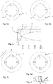
- the regulating body 2 is mounted on the inflow side 3 of a main body 4.
- a control gap 5 is formed between the main body 4 and the regulating body 2.
- an essentially circular drain opening 6 is formed through which the water will flow out of the flow rate regulator 1.
- the regulating body 2 Depending on the pressure applied on the regulating body 2, i.e. the inflow pressure or a pressure difference across the flow rate regulator 1, the regulating body 2 will be deformed. This results in a change of the area of the control gap 5, measured perpendicularly with respect to the direction of flow in the control gap 5.
- the regulating body 2 is divided into regions 7 that are adjacent to each other.
- the regions 7 can be grouped as high-pressure regions 8 and low-pressure regions 9.
- a supporting element 10 is arranged to support the regulating body 2 at low pressures even below 0,1 bar. This is achieved by letting the supporting element 10 contact the regulating body 2 at zero pressure. This contact effectively decouples the portions of the regulating body 2 in adjacent regions 7.
- the supporting elements 10 are formed integrally with the main body 2 as fixed protrusions 11.
- the supporting elements 10 which define a high-pressure region 8 are arranged closer together than supporting elements 10 which define a low-pressure region 9.
- a distance 12, in this case measured as an angular distance, between supporting elements 10 confining a high-pressure region 8, is considerably shorter than a distance 13, also in this case measured as an angular distance, between supporting elements 10 confining a low-pressure region 9.
- the distances 12, 13 may be measured along straight lines.
- the regulating body 2 spans a smaller distance 12 in a high-pressure region 8 while it spans a larger distance 13 in a low-pressure region 9.
- the high-pressure region 8 is formed by a groove 14.
- the depth of this groove 14 is such that the regulation body 2 will not, even at very high pressures achievable in sanitary systems, touch its ground 15.
- this is achieved by a rectangular cross section of the groove 14 wherein the width is much smaller than the height of the groove 14.
- the supporting elements 10 that define the low-pressure region 9 as a boundary are spaced apart such that the regulating body 2 will, above a certain pressure threshold, contact the main body 4 along the full or essentially full size of the low-pressure region 9. Thus, no water will flow through the control gap 5 in the low-pressure region 9 above said pressure threshold.
- the supporting elements 10 fall off less rapidly on the low-pressure side than they do in the high-pressure side.
- the contour forming the control gap 5 describes a trough 30 with tilted side walls 31, 32.
- an intermediate element 16 in addition. This is formed by a protrusion 17 of smaller size compared to the supporting elements 10.
- the height of the intermediate element 16 may be, for example, less than half or less than one third the height of the supporting elements 10.
- the height of the intermediate element 16 is such that it does not contact the regulating body 2 at zero pressure, i.e. in an undeformed state of the regulating body 2.
- Fig. 2 shows a further exemplary embodiment according to the invention.
- Components and functional units that are structurally and/or functionally similar or identical to the preceding exemplary embodiment are denoted by the same reference signs and not described separately.
- the information given with respect to Figure 1 therefore applies, mutatis mutandis , to Fig. 2 .
- Fig. 1 While in the embodiment of Fig. 1 , high-pressure regions 8 and low-pressure regions 9 are arranged such that they form an alternating sequence, in the embodiment of Fig. 2 there is a sequence of several consecutive high-pressure regions 8 that are adjacent to each other. In other words, the apparent fourfold symmetry of the arrangement of Fig. 1 is not necessary to achieve the benefits of the invention. However, the arrangement of Fig. 1 is preferred for most case due to its simplicity in design.
- one single low-pressure region is formed that stretches as far as possible, i.e. more than 270°.
- inventions may have more or less than three high-pressure regions.
- Fig. 3 shows a third exemplary embodiment according to the invention.
- Components and functional units that are structurally and/or functionally similar or identical to the preceding exemplary embodiment are denoted by the same reference signs and not described separately.
- the information given with respect to Figures 1 and 2 therefore applies, mutatis mutandis , to Fig. 3 .
- the high-pressure regions have inwardly tilted side walls 31, 32 in order to further prevent the regulating body 2 from fully closing the control gap 5.
- Such inwardly tilted side walls 31, 32 may be used in the other designs as well.
- some of the projections 11, 17 may be projecting outwardly while others may project inwardly.
- recessions 20 Between adjacent protrusions 11, 17, there are formed recessions 20.
- the sequence of protrusions 11, 17 and recessions 20 define a regulating profile 21.
- the flow rate regulators 1 of Fig. 1 to 3 are of the ring type.
- the regulating bodies 2 are form as rings 18.
- the rings 18 have a circular shape, so that the regulating bodies 2 can be O-rings 19.
- the regulating body 2 is deformed in a direction perpendicular or laterally to the main direction of flow 35 (which is itself is parallel to the direction of view in Figures 1 to 3 ).
- Figure 2 shows webs 33 in the drain opening 6 on which the regulating body 2 rests. A similar construction is present in the other embodiments as well, although not shown there.
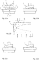
- Figure 4 shows a control curve 22 of the flow rate regulator 1 of Fig. 1 . Similar curves will apply for the flow rate regulators of Figures 2 and 3 .
- the control curve 22 shows the dependence of the flow rate through the drain opening 6 on the pressure difference across the flow rate regulator 1.
- the control curve 22 is the sum of the control curve 23 of the high-pressure regions 8 and the control curve 24 of the high-pressure regions 9.
- the control curve 23 of the high-pressure region 8 intersects the control curve 24 of the low-pressure region 9 at an intersection point 40.
- Control curve 23 shows that the low-pressure region 9 does not contribute in an essential way above a pressure threshold approximately at c.
- a maximum - here a limit value approximately at the constant flow level - of the control curve 23 of the high-pressure region 8 lies at a pressure above a pressure of the intersection point 40.
- a maximum - here the kink 34 - of the control curve 24 of the low-pressure region 9 lies at a pressure below the pressure of said intersection point 40.
- Figures 5a through 5d show the corresponding deformation of the regulating body 2 at the respective pressures a ( Fig. 5a ), b ( Fig. 5b ), c ( Fig. 5c ), d ( Fig. 5d ) of Fig. 4 .
- control gap 5 is essentially closed in the low-pressure regions 9.
- the remaining area in the low-pressure regions 9 may be less than one third of the total cross sectional area of the control gap 5 at this pressure. Hence, essentially all flow is going through the high-pressure regions 8.
- Figures 7 to 9 show a forth exemplary embodiment according to the invention.
- Components and functional units that are structurally and/or functionally similar or identical to the preceding exemplary embodiment are denoted by the same reference signs and not described separately.
- the information given with respect to Figures 1 to 3 therefore applies, mutatis mutandis , to Figures 7 to 9 .
- the flow rate regulator 1 of Figures 7 to 9 is of the disc type.
- the regulating body 2 is shaped like a washer and made of elastically deformable material like rubber.
- the regulating body 2 is set on a pin 36 and rests on a shoulder 37.
- the pin 36 penetrates the regulation body 2 at a central hole.
- the deformation of the regulating body 2 is - unlike to Figures 1 to 6 - in or longitudinally to the main direction of the flow 35 (i.e. the direction of view in Fig. 9 ).
- the supporting elements 10 are of identical height at or above the position of the shoulder 37. Thus, the supporting elements 10 contact the regulating body 2 already at zero pressure.
- the regulating body 2 extends somewhat beyond that disc-like region 27 so that it covers the drain opening 6.
- the drain opening 6, in turn, has an essentially (where the supporting elements 10 and the intermediate elements 16 are neglected) circular outer periphery 29.
- an outer contour 38 of the drain opening 6 describes a section of a circle 39.
- the circle 39 coincides with a boundary of the disc-like region 27.
- the drain opening 6 is fully contained within said circle 39, while the contact surface 38 extends beyond it.
- a continuous surface 28 is formed on the main body 4.
- the height of supporting elements 10 in relation to the distance 12 is such that the regulating body 2 cannot reach the continuous surface 28. Hence, the control gap 5 remains at least partially open at all pressure levels.
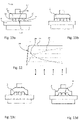
- Figure 10 shows a control curve 22 of the flow rate regulator 1 of Figures 7 to 9 .
- the explanations given to Figure 4 also apply here.
- Figures 11a through 11d show the corresponding deformation of the regulating body 2 at the respective pressures a ( Fig. 11a ), b ( Fig. 11b ), c ( Fig. 11c ), d ( Fig. 11d ) of Fig. 10 when the low-pressure region 9 of flow rate regulator 1 is viewed.
- Figures 13a through 13d show the corresponding deformation of the regulating body 2 at the respective pressures a ( Fig. 13a ), b ( Fig. 13b ), c ( Fig. 13c ), d ( Fig. 13d ) of Fig. 10 when the high-pressure region 8 of flow rate regulator 1 is viewed. To assist in reading, the content of Figure 10 is repeated as Figure 12 .
- Figure 11a clearly shows that the height of the intermediate element 16 is less than 1/5 of the height of the supporting elements 10.
Landscapes
- Physics & Mathematics (AREA)
- General Physics & Mathematics (AREA)
- Engineering & Computer Science (AREA)
- Automation & Control Theory (AREA)
- Fluid Mechanics (AREA)
- Flow Control (AREA)
- Safety Valves (AREA)
Applications Claiming Priority (2)
| Application Number | Priority Date | Filing Date | Title |
|---|---|---|---|
| DE202017101427.4U DE202017101427U1 (de) | 2017-03-13 | 2017-03-13 | Durchflussmengenregler |
| PCT/EP2018/056223 WO2018167052A1 (en) | 2017-03-13 | 2018-03-13 | Flow rate regulator |
Publications (2)
| Publication Number | Publication Date |
|---|---|
| EP3596573A1 EP3596573A1 (en) | 2020-01-22 |
| EP3596573B1 true EP3596573B1 (en) | 2022-04-27 |
Family
ID=61683772
Family Applications (2)
| Application Number | Title | Priority Date | Filing Date |
|---|---|---|---|
| EP18711525.8A Active EP3596573B1 (en) | 2017-03-13 | 2018-03-13 | Flow rate regulator |
| EP18711524.1A Active EP3519907B1 (de) | 2017-03-13 | 2018-03-13 | Durchflussmengenregler |
Family Applications After (1)
| Application Number | Title | Priority Date | Filing Date |
|---|---|---|---|
| EP18711524.1A Active EP3519907B1 (de) | 2017-03-13 | 2018-03-13 | Durchflussmengenregler |
Country Status (7)
| Country | Link |
|---|---|
| US (2) | US11630468B2 (pl) |
| EP (2) | EP3596573B1 (pl) |
| CN (2) | CN110235082B (pl) |
| DE (1) | DE202017101427U1 (pl) |
| ES (1) | ES2767733T3 (pl) |
| PL (1) | PL3519907T3 (pl) |
| WO (2) | WO2018167051A1 (pl) |
Families Citing this family (4)
| Publication number | Priority date | Publication date | Assignee | Title |
|---|---|---|---|---|
| USD920477S1 (en) * | 2019-03-08 | 2021-05-25 | Neoperl Gmbh | Converter for sanitary outlet valves |
| DE202019103892U1 (de) | 2019-07-15 | 2020-10-16 | Neoperl Gmbh | Mengenreglereinheit und korrespondierende Verwendung |
| JP1738032S (ja) * | 2022-01-27 | 2023-03-01 | 給水栓 | |
| USD989230S1 (en) * | 2022-08-05 | 2023-06-13 | Xiamen Water Nymph Sanitary Technology Co., Ltd. | Aerator body |
Citations (1)
| Publication number | Priority date | Publication date | Assignee | Title |
|---|---|---|---|---|
| US20140014216A1 (en) * | 2012-07-12 | 2014-01-16 | Delta Electronics, Inc. | Flow Stabilizer |
Family Cites Families (44)
| Publication number | Priority date | Publication date | Assignee | Title |
|---|---|---|---|---|
| US2444677A (en) | 1946-12-14 | 1948-07-06 | Dole Valve Co | Flow control device |
| US2960109A (en) | 1957-01-07 | 1960-11-15 | Gen Controls Co | Flow regulator |
| SE397736B (sv) * | 1970-12-10 | 1977-11-14 | Mannesmann & Keppel | Vetskemengdregulator |
| MC1124A1 (fr) * | 1976-07-20 | 1977-08-12 | G Grandclement | Perfectionnement dans les regulations de debits des vannes |
| US4230149A (en) * | 1978-05-22 | 1980-10-28 | Eaton Corporation | Fluid flow regulating valve and system |
| FI69355C (fi) * | 1983-05-20 | 1986-01-10 | Halton Oy | Stroemningsregulator |
| FI72384C (fi) * | 1983-05-20 | 1987-05-11 | Halton Oy | Stroemningsregulator och anvaendning av denna. |
| US5409042A (en) * | 1993-07-29 | 1995-04-25 | Romac Industries, Inc. | Constant-rate flow control valve |
| CN1062056C (zh) * | 1994-02-19 | 2001-02-14 | 株式会社日立制作所 | 箱型成套螺杆压缩机 |
| IT232593Y1 (it) | 1994-12-19 | 2000-01-10 | Vernelli Maria | Regolatore idraulico di portata. |
| US5771921A (en) * | 1995-09-19 | 1998-06-30 | Ctb, Inc. | Pressure regulator |
| DE19932596C2 (de) * | 1999-07-13 | 2002-10-17 | Wildfang Dieter Gmbh | Durchflußmengenregler |
| US6584977B1 (en) * | 2000-04-06 | 2003-07-01 | Respironics, Inc. | Combined patient interface and exhaust assembly |
| US6390122B1 (en) * | 2000-10-11 | 2002-05-21 | Hays Fluid Controls, A Division Of Romac Industries, Inc. | Fluid flow control valve and orifice therefor |
| ITTO20011206A1 (it) | 2001-12-21 | 2003-06-21 | Eltek Spa | Dispositivo regolatore del flusso di un fluido, in particolare per elettrovalvole. |
| JP4352783B2 (ja) * | 2002-08-23 | 2009-10-28 | 東京エレクトロン株式会社 | ガス供給系及び処理システム |
| DE202005004195U1 (de) * | 2005-03-14 | 2006-07-27 | Neoperl Gmbh | Durchflußmengenregler |
| US20070169262A1 (en) | 2005-10-10 | 2007-07-26 | Mcdonald Christopher W | Flow control assembly for a shower head |
| DE102006057787B3 (de) * | 2006-12-06 | 2008-05-29 | Neoperl Gmbh | Durchflussmengenregler |
| DE202006018577U1 (de) * | 2006-12-06 | 2007-12-20 | Neoperl Gmbh | Sanitäres Einbauelement |
| CA2676180A1 (en) * | 2007-01-24 | 2008-07-31 | I2O Water Limited | Controller and control system for a pressure reducing valve |
| CL2008000317A1 (es) * | 2008-02-01 | 2008-03-28 | Servicios Asoc A M Limitada | Piloto para valvula reguladora de presion que tiene una tuberia de comunicacion, entre la camara de la valvula y una fuente de presion alta, que esta interrumpida por un elemento de cierre con accionamiento electrico. |
| DE102009011343B4 (de) * | 2009-03-05 | 2013-11-07 | Neoperl Gmbh | Durchflussmengenregler |
| DE102010005033A1 (de) * | 2010-01-15 | 2011-07-21 | Sig Technology Ag | Verfahren und Vorrichtung zum Abfüllen von Produkten |
| DE102010055459A1 (de) * | 2010-05-27 | 2011-12-01 | Neoperl Gmbh | Sanitärer Auslaufeinsatz |
| UA106431C2 (ru) * | 2010-06-10 | 2014-08-26 | Данфосс А/С | Способ регулировки однотрубной системы теплоснабжения |
| DE102011120007A1 (de) * | 2011-03-11 | 2012-09-13 | Neoperl Gmbh | Sanitäres Durchflusselement mit einer Durchflussmengenregler-Einheit |
| ITTO20110615A1 (it) | 2011-07-13 | 2013-01-14 | Elbi Int Spa | Regolatore idraulico di portata |
| DE202013002281U1 (de) | 2013-03-11 | 2014-06-12 | Neoperl Gmbh | Sanitäres Einbauteil und Duschanordnung |
| JP2014174139A (ja) * | 2013-03-13 | 2014-09-22 | Sony Corp | 流路デバイス、粒子分取装置、粒子流出方法、及び粒子分取方法 |
| NL2011765C2 (nl) | 2013-11-08 | 2015-05-19 | Vitaplus Nederland B V | Inrichting en werkwijze voor het begrenzen van de hoeveelheid fluïdum. |
| EP2988071B1 (de) * | 2014-08-19 | 2016-06-22 | IMI Hydronic Engineering International SA | Durchflussmengenregler |
| DE202015000855U1 (de) * | 2015-02-03 | 2016-05-04 | Neoperl Gmbh | Sanitäre Einsetzeinheit |
| DE202015001757U1 (de) * | 2015-03-09 | 2016-06-10 | Neoperl Gmbh | Sanitäre Einsetzeinheit |
| US10054247B2 (en) * | 2015-03-31 | 2018-08-21 | Emerson Process Management Regulator Technologies, Inc. | Fluid regulators |
| CN205481672U (zh) * | 2016-02-05 | 2016-08-17 | 佛山市云米电器科技有限公司 | 一种水道加热装置的密封体 |
| DE102016112514A1 (de) * | 2016-07-07 | 2018-01-11 | A. u. K. Müller GmbH & Co. KG | Mengenregler für ein Ventil |
| DE102016011168B4 (de) * | 2016-09-16 | 2026-02-26 | Neoperl Gmbh | Sanitäre Einheit |
| USD904567S1 (en) * | 2016-10-31 | 2020-12-08 | Neoperl Gmbh | Sanitary outlet valve |
| DE202017101236U1 (de) * | 2017-03-03 | 2018-06-05 | Neoperl Gmbh | Durchflussmengenregler |
| DE202017101398U1 (de) * | 2017-03-10 | 2018-06-12 | Neoperl Gmbh | Sanitäres Einsetzteil und Verwendung eines solchen |
| US20200268947A1 (en) * | 2017-08-25 | 2020-08-27 | Strataca Systems Limited | Pump Assembly and System for Inducing Negative Pressure in a Portion of a Urinary Tract of a Patient |
| DE202018102383U1 (de) * | 2018-04-27 | 2019-07-30 | Neoperl Gmbh | Durchflussmengenregler |
| JP6927180B2 (ja) * | 2018-10-22 | 2021-08-25 | 浜名湖電装株式会社 | 流体制御弁 |
-
2017
- 2017-03-13 DE DE202017101427.4U patent/DE202017101427U1/de active Active
-
2018
- 2018-03-13 ES ES18711524T patent/ES2767733T3/es active Active
- 2018-03-13 WO PCT/EP2018/056222 patent/WO2018167051A1/de not_active Ceased
- 2018-03-13 EP EP18711525.8A patent/EP3596573B1/en active Active
- 2018-03-13 US US16/479,756 patent/US11630468B2/en active Active
- 2018-03-13 US US16/476,981 patent/US11327509B2/en active Active
- 2018-03-13 CN CN201880009089.4A patent/CN110235082B/zh active Active
- 2018-03-13 CN CN201880004949.5A patent/CN110050244B/zh active Active
- 2018-03-13 PL PL18711524T patent/PL3519907T3/pl unknown
- 2018-03-13 EP EP18711524.1A patent/EP3519907B1/de active Active
- 2018-03-13 WO PCT/EP2018/056223 patent/WO2018167052A1/en not_active Ceased
Patent Citations (1)
| Publication number | Priority date | Publication date | Assignee | Title |
|---|---|---|---|---|
| US20140014216A1 (en) * | 2012-07-12 | 2014-01-16 | Delta Electronics, Inc. | Flow Stabilizer |
Also Published As
| Publication number | Publication date |
|---|---|
| CN110235082A (zh) | 2019-09-13 |
| DE202017101427U1 (de) | 2018-06-14 |
| US11327509B2 (en) | 2022-05-10 |
| US11630468B2 (en) | 2023-04-18 |
| ES2767733T3 (es) | 2020-06-18 |
| CN110050244B (zh) | 2022-08-30 |
| EP3596573A1 (en) | 2020-01-22 |
| WO2018167052A1 (en) | 2018-09-20 |
| US20210325913A1 (en) | 2021-10-21 |
| EP3519907B1 (de) | 2019-12-11 |
| CN110050244A (zh) | 2019-07-23 |
| PL3519907T3 (pl) | 2020-06-01 |
| EP3519907A1 (de) | 2019-08-07 |
| CN110235082B (zh) | 2022-07-15 |
| WO2018167051A1 (de) | 2018-09-20 |
| BR112019011151A2 (pt) | 2019-10-01 |
| US20190391600A1 (en) | 2019-12-26 |
Similar Documents
| Publication | Publication Date | Title |
|---|---|---|
| EP3596573B1 (en) | Flow rate regulator | |
| CN106200699B (zh) | 流量调节器单元 | |
| US20130153808A1 (en) | Anti-cavitation valve seat | |
| JP4386610B2 (ja) | 流量調整器 | |
| EP2914889B1 (en) | Valve cage having zero dead band between noise abatement and high capacity flow sections | |
| JP2007333207A (ja) | 圧力調節弁 | |
| US20120097254A1 (en) | Flow regulator for agricultural drip emitter | |
| KR20010014725A (ko) | 역류방지장치 | |
| JP2008232196A (ja) | 定流量制御装置 | |
| US20100294971A1 (en) | Valve diaphragm | |
| US5050635A (en) | Relief valve | |
| US11914405B2 (en) | Flow rate regulator | |
| JP6407441B2 (ja) | 圧力除去要素を備える封止装置と、中間領域圧力カスケードを生じさせるための該封止装置の使用方法 | |
| US10512920B2 (en) | Sanitary insertion unit | |
| EP3193051B1 (en) | Valve arrangement and insert for a valve arrangement | |
| KR100285080B1 (ko) | 유압장치 | |
| KR100794567B1 (ko) | 온수 분배기용 밸런싱 밸브 | |
| BR112019011151B1 (pt) | Regulador de vazão | |
| JP2006292115A (ja) | 流量調整装置 | |
| JP7687417B2 (ja) | スプール弁 | |
| EP3997541B1 (en) | Fluid flow regulator | |
| KR102698626B1 (ko) | 유량 제어 모듈 |
Legal Events
| Date | Code | Title | Description |
|---|---|---|---|
| STAA | Information on the status of an ep patent application or granted ep patent |
Free format text: STATUS: UNKNOWN |
|
| STAA | Information on the status of an ep patent application or granted ep patent |
Free format text: STATUS: THE INTERNATIONAL PUBLICATION HAS BEEN MADE |
|
| PUAI | Public reference made under article 153(3) epc to a published international application that has entered the european phase |
Free format text: ORIGINAL CODE: 0009012 |
|
| STAA | Information on the status of an ep patent application or granted ep patent |
Free format text: STATUS: REQUEST FOR EXAMINATION WAS MADE |
|
| 17P | Request for examination filed |
Effective date: 20191014 |
|
| AK | Designated contracting states |
Kind code of ref document: A1 Designated state(s): AL AT BE BG CH CY CZ DE DK EE ES FI FR GB GR HR HU IE IS IT LI LT LU LV MC MK MT NL NO PL PT RO RS SE SI SK SM TR |
|
| AX | Request for extension of the european patent |
Extension state: BA ME |
|
| DAV | Request for validation of the european patent (deleted) | ||
| DAX | Request for extension of the european patent (deleted) | ||
| STAA | Information on the status of an ep patent application or granted ep patent |
Free format text: STATUS: EXAMINATION IS IN PROGRESS |
|
| 17Q | First examination report despatched |
Effective date: 20200817 |
|
| GRAP | Despatch of communication of intention to grant a patent |
Free format text: ORIGINAL CODE: EPIDOSNIGR1 |
|
| STAA | Information on the status of an ep patent application or granted ep patent |
Free format text: STATUS: GRANT OF PATENT IS INTENDED |
|
| INTG | Intention to grant announced |
Effective date: 20211105 |
|
| GRAS | Grant fee paid |
Free format text: ORIGINAL CODE: EPIDOSNIGR3 |
|
| GRAA | (expected) grant |
Free format text: ORIGINAL CODE: 0009210 |
|
| STAA | Information on the status of an ep patent application or granted ep patent |
Free format text: STATUS: THE PATENT HAS BEEN GRANTED |
|
| AK | Designated contracting states |
Kind code of ref document: B1 Designated state(s): AL AT BE BG CH CY CZ DE DK EE ES FI FR GB GR HR HU IE IS IT LI LT LU LV MC MK MT NL NO PL PT RO RS SE SI SK SM TR |
|
| REG | Reference to a national code |
Ref country code: GB Ref legal event code: FG4D |
|
| REG | Reference to a national code |
Ref country code: CH Ref legal event code: EP |
|
| REG | Reference to a national code |
Ref country code: DE Ref legal event code: R096 Ref document number: 602018034502 Country of ref document: DE |
|
| REG | Reference to a national code |
Ref country code: AT Ref legal event code: REF Ref document number: 1487431 Country of ref document: AT Kind code of ref document: T Effective date: 20220515 |
|
| REG | Reference to a national code |
Ref country code: IE Ref legal event code: FG4D |
|
| REG | Reference to a national code |
Ref country code: LT Ref legal event code: MG9D |
|
| REG | Reference to a national code |
Ref country code: NL Ref legal event code: MP Effective date: 20220427 |
|
| REG | Reference to a national code |
Ref country code: AT Ref legal event code: MK05 Ref document number: 1487431 Country of ref document: AT Kind code of ref document: T Effective date: 20220427 |
|
| PG25 | Lapsed in a contracting state [announced via postgrant information from national office to epo] |
Ref country code: NL Free format text: LAPSE BECAUSE OF FAILURE TO SUBMIT A TRANSLATION OF THE DESCRIPTION OR TO PAY THE FEE WITHIN THE PRESCRIBED TIME-LIMIT Effective date: 20220427 |
|
| PG25 | Lapsed in a contracting state [announced via postgrant information from national office to epo] |
Ref country code: SE Free format text: LAPSE BECAUSE OF FAILURE TO SUBMIT A TRANSLATION OF THE DESCRIPTION OR TO PAY THE FEE WITHIN THE PRESCRIBED TIME-LIMIT Effective date: 20220427 Ref country code: PT Free format text: LAPSE BECAUSE OF FAILURE TO SUBMIT A TRANSLATION OF THE DESCRIPTION OR TO PAY THE FEE WITHIN THE PRESCRIBED TIME-LIMIT Effective date: 20220829 Ref country code: NO Free format text: LAPSE BECAUSE OF FAILURE TO SUBMIT A TRANSLATION OF THE DESCRIPTION OR TO PAY THE FEE WITHIN THE PRESCRIBED TIME-LIMIT Effective date: 20220727 Ref country code: LT Free format text: LAPSE BECAUSE OF FAILURE TO SUBMIT A TRANSLATION OF THE DESCRIPTION OR TO PAY THE FEE WITHIN THE PRESCRIBED TIME-LIMIT Effective date: 20220427 Ref country code: HR Free format text: LAPSE BECAUSE OF FAILURE TO SUBMIT A TRANSLATION OF THE DESCRIPTION OR TO PAY THE FEE WITHIN THE PRESCRIBED TIME-LIMIT Effective date: 20220427 Ref country code: GR Free format text: LAPSE BECAUSE OF FAILURE TO SUBMIT A TRANSLATION OF THE DESCRIPTION OR TO PAY THE FEE WITHIN THE PRESCRIBED TIME-LIMIT Effective date: 20220728 Ref country code: FI Free format text: LAPSE BECAUSE OF FAILURE TO SUBMIT A TRANSLATION OF THE DESCRIPTION OR TO PAY THE FEE WITHIN THE PRESCRIBED TIME-LIMIT Effective date: 20220427 Ref country code: ES Free format text: LAPSE BECAUSE OF FAILURE TO SUBMIT A TRANSLATION OF THE DESCRIPTION OR TO PAY THE FEE WITHIN THE PRESCRIBED TIME-LIMIT Effective date: 20220427 Ref country code: BG Free format text: LAPSE BECAUSE OF FAILURE TO SUBMIT A TRANSLATION OF THE DESCRIPTION OR TO PAY THE FEE WITHIN THE PRESCRIBED TIME-LIMIT Effective date: 20220727 Ref country code: AT Free format text: LAPSE BECAUSE OF FAILURE TO SUBMIT A TRANSLATION OF THE DESCRIPTION OR TO PAY THE FEE WITHIN THE PRESCRIBED TIME-LIMIT Effective date: 20220427 |
|
| PG25 | Lapsed in a contracting state [announced via postgrant information from national office to epo] |
Ref country code: RS Free format text: LAPSE BECAUSE OF FAILURE TO SUBMIT A TRANSLATION OF THE DESCRIPTION OR TO PAY THE FEE WITHIN THE PRESCRIBED TIME-LIMIT Effective date: 20220427 Ref country code: PL Free format text: LAPSE BECAUSE OF FAILURE TO SUBMIT A TRANSLATION OF THE DESCRIPTION OR TO PAY THE FEE WITHIN THE PRESCRIBED TIME-LIMIT Effective date: 20220427 Ref country code: LV Free format text: LAPSE BECAUSE OF FAILURE TO SUBMIT A TRANSLATION OF THE DESCRIPTION OR TO PAY THE FEE WITHIN THE PRESCRIBED TIME-LIMIT Effective date: 20220427 Ref country code: IS Free format text: LAPSE BECAUSE OF FAILURE TO SUBMIT A TRANSLATION OF THE DESCRIPTION OR TO PAY THE FEE WITHIN THE PRESCRIBED TIME-LIMIT Effective date: 20220827 |
|
| REG | Reference to a national code |
Ref country code: DE Ref legal event code: R097 Ref document number: 602018034502 Country of ref document: DE |
|
| PG25 | Lapsed in a contracting state [announced via postgrant information from national office to epo] |
Ref country code: SM Free format text: LAPSE BECAUSE OF FAILURE TO SUBMIT A TRANSLATION OF THE DESCRIPTION OR TO PAY THE FEE WITHIN THE PRESCRIBED TIME-LIMIT Effective date: 20220427 Ref country code: SK Free format text: LAPSE BECAUSE OF FAILURE TO SUBMIT A TRANSLATION OF THE DESCRIPTION OR TO PAY THE FEE WITHIN THE PRESCRIBED TIME-LIMIT Effective date: 20220427 Ref country code: RO Free format text: LAPSE BECAUSE OF FAILURE TO SUBMIT A TRANSLATION OF THE DESCRIPTION OR TO PAY THE FEE WITHIN THE PRESCRIBED TIME-LIMIT Effective date: 20220427 Ref country code: EE Free format text: LAPSE BECAUSE OF FAILURE TO SUBMIT A TRANSLATION OF THE DESCRIPTION OR TO PAY THE FEE WITHIN THE PRESCRIBED TIME-LIMIT Effective date: 20220427 Ref country code: DK Free format text: LAPSE BECAUSE OF FAILURE TO SUBMIT A TRANSLATION OF THE DESCRIPTION OR TO PAY THE FEE WITHIN THE PRESCRIBED TIME-LIMIT Effective date: 20220427 Ref country code: CZ Free format text: LAPSE BECAUSE OF FAILURE TO SUBMIT A TRANSLATION OF THE DESCRIPTION OR TO PAY THE FEE WITHIN THE PRESCRIBED TIME-LIMIT Effective date: 20220427 |
|
| PLBE | No opposition filed within time limit |
Free format text: ORIGINAL CODE: 0009261 |
|
| STAA | Information on the status of an ep patent application or granted ep patent |
Free format text: STATUS: NO OPPOSITION FILED WITHIN TIME LIMIT |
|
| PG25 | Lapsed in a contracting state [announced via postgrant information from national office to epo] |
Ref country code: AL Free format text: LAPSE BECAUSE OF FAILURE TO SUBMIT A TRANSLATION OF THE DESCRIPTION OR TO PAY THE FEE WITHIN THE PRESCRIBED TIME-LIMIT Effective date: 20220427 |
|
| 26N | No opposition filed |
Effective date: 20230130 |
|
| PG25 | Lapsed in a contracting state [announced via postgrant information from national office to epo] |
Ref country code: SI Free format text: LAPSE BECAUSE OF FAILURE TO SUBMIT A TRANSLATION OF THE DESCRIPTION OR TO PAY THE FEE WITHIN THE PRESCRIBED TIME-LIMIT Effective date: 20220427 |
|
| PG25 | Lapsed in a contracting state [announced via postgrant information from national office to epo] |
Ref country code: MC Free format text: LAPSE BECAUSE OF FAILURE TO SUBMIT A TRANSLATION OF THE DESCRIPTION OR TO PAY THE FEE WITHIN THE PRESCRIBED TIME-LIMIT Effective date: 20220427 |
|
| REG | Reference to a national code |
Ref country code: CH Ref legal event code: PL |
|
| REG | Reference to a national code |
Ref country code: BE Ref legal event code: MM Effective date: 20230331 |
|
| PG25 | Lapsed in a contracting state [announced via postgrant information from national office to epo] |
Ref country code: LU Free format text: LAPSE BECAUSE OF NON-PAYMENT OF DUE FEES Effective date: 20230313 |
|
| REG | Reference to a national code |
Ref country code: IE Ref legal event code: MM4A |
|
| PG25 | Lapsed in a contracting state [announced via postgrant information from national office to epo] |
Ref country code: LI Free format text: LAPSE BECAUSE OF NON-PAYMENT OF DUE FEES Effective date: 20230331 Ref country code: IE Free format text: LAPSE BECAUSE OF NON-PAYMENT OF DUE FEES Effective date: 20230313 Ref country code: FR Free format text: LAPSE BECAUSE OF NON-PAYMENT OF DUE FEES Effective date: 20230331 Ref country code: CH Free format text: LAPSE BECAUSE OF NON-PAYMENT OF DUE FEES Effective date: 20230331 |
|
| PG25 | Lapsed in a contracting state [announced via postgrant information from national office to epo] |
Ref country code: BE Free format text: LAPSE BECAUSE OF NON-PAYMENT OF DUE FEES Effective date: 20230331 |
|
| PG25 | Lapsed in a contracting state [announced via postgrant information from national office to epo] |
Ref country code: BG Free format text: LAPSE BECAUSE OF FAILURE TO SUBMIT A TRANSLATION OF THE DESCRIPTION OR TO PAY THE FEE WITHIN THE PRESCRIBED TIME-LIMIT Effective date: 20220427 |
|
| PG25 | Lapsed in a contracting state [announced via postgrant information from national office to epo] |
Ref country code: BG Free format text: LAPSE BECAUSE OF FAILURE TO SUBMIT A TRANSLATION OF THE DESCRIPTION OR TO PAY THE FEE WITHIN THE PRESCRIBED TIME-LIMIT Effective date: 20220427 |
|
| PGFP | Annual fee paid to national office [announced via postgrant information from national office to epo] |
Ref country code: DE Payment date: 20250513 Year of fee payment: 8 |
|
| PGFP | Annual fee paid to national office [announced via postgrant information from national office to epo] |
Ref country code: IT Payment date: 20250331 Year of fee payment: 8 |
|
| PG25 | Lapsed in a contracting state [announced via postgrant information from national office to epo] |
Ref country code: CY Free format text: LAPSE BECAUSE OF FAILURE TO SUBMIT A TRANSLATION OF THE DESCRIPTION OR TO PAY THE FEE WITHIN THE PRESCRIBED TIME-LIMIT; INVALID AB INITIO Effective date: 20180313 |
|
| PG25 | Lapsed in a contracting state [announced via postgrant information from national office to epo] |
Ref country code: HU Free format text: LAPSE BECAUSE OF FAILURE TO SUBMIT A TRANSLATION OF THE DESCRIPTION OR TO PAY THE FEE WITHIN THE PRESCRIBED TIME-LIMIT; INVALID AB INITIO Effective date: 20180313 |
|
| PG25 | Lapsed in a contracting state [announced via postgrant information from national office to epo] |
Ref country code: TR Free format text: LAPSE BECAUSE OF FAILURE TO SUBMIT A TRANSLATION OF THE DESCRIPTION OR TO PAY THE FEE WITHIN THE PRESCRIBED TIME-LIMIT Effective date: 20220427 |
|
| PGFP | Annual fee paid to national office [announced via postgrant information from national office to epo] |
Ref country code: GB Payment date: 20260324 Year of fee payment: 9 |