EP3595047A2 - Sekundärbatterieelektrode, herstellungsverfahren dafür und elektrodenanordnung - Google Patents
Sekundärbatterieelektrode, herstellungsverfahren dafür und elektrodenanordnung Download PDFInfo
- Publication number
- EP3595047A2 EP3595047A2 EP18849036.1A EP18849036A EP3595047A2 EP 3595047 A2 EP3595047 A2 EP 3595047A2 EP 18849036 A EP18849036 A EP 18849036A EP 3595047 A2 EP3595047 A2 EP 3595047A2
- Authority
- EP
- European Patent Office
- Prior art keywords
- active material
- material layer
- current collector
- electrode
- protruding portion
- Prior art date
- Legal status (The legal status is an assumption and is not a legal conclusion. Google has not performed a legal analysis and makes no representation as to the accuracy of the status listed.)
- Granted
Links
Images


Classifications
-
- H—ELECTRICITY
- H01—ELECTRIC ELEMENTS
- H01M—PROCESSES OR MEANS, e.g. BATTERIES, FOR THE DIRECT CONVERSION OF CHEMICAL ENERGY INTO ELECTRICAL ENERGY
- H01M10/00—Secondary cells; Manufacture thereof
- H01M10/04—Construction or manufacture in general
- H01M10/0404—Machines for assembling batteries
-
- H—ELECTRICITY
- H01—ELECTRIC ELEMENTS
- H01M—PROCESSES OR MEANS, e.g. BATTERIES, FOR THE DIRECT CONVERSION OF CHEMICAL ENERGY INTO ELECTRICAL ENERGY
- H01M4/00—Electrodes
- H01M4/02—Electrodes composed of, or comprising, active material
- H01M4/36—Selection of substances as active materials, active masses, active liquids
- H01M4/362—Composites
- H01M4/366—Composites as layered products
-
- H—ELECTRICITY
- H01—ELECTRIC ELEMENTS
- H01M—PROCESSES OR MEANS, e.g. BATTERIES, FOR THE DIRECT CONVERSION OF CHEMICAL ENERGY INTO ELECTRICAL ENERGY
- H01M4/00—Electrodes
- H01M4/02—Electrodes composed of, or comprising, active material
-
- H—ELECTRICITY
- H01—ELECTRIC ELEMENTS
- H01M—PROCESSES OR MEANS, e.g. BATTERIES, FOR THE DIRECT CONVERSION OF CHEMICAL ENERGY INTO ELECTRICAL ENERGY
- H01M10/00—Secondary cells; Manufacture thereof
- H01M10/04—Construction or manufacture in general
- H01M10/0431—Cells with wound or folded electrodes
-
- H—ELECTRICITY
- H01—ELECTRIC ELEMENTS
- H01M—PROCESSES OR MEANS, e.g. BATTERIES, FOR THE DIRECT CONVERSION OF CHEMICAL ENERGY INTO ELECTRICAL ENERGY
- H01M10/00—Secondary cells; Manufacture thereof
- H01M10/05—Accumulators with non-aqueous electrolyte
- H01M10/052—Li-accumulators
- H01M10/0525—Rocking-chair batteries, i.e. batteries with lithium insertion or intercalation in both electrodes; Lithium-ion batteries
-
- H—ELECTRICITY
- H01—ELECTRIC ELEMENTS
- H01M—PROCESSES OR MEANS, e.g. BATTERIES, FOR THE DIRECT CONVERSION OF CHEMICAL ENERGY INTO ELECTRICAL ENERGY
- H01M10/00—Secondary cells; Manufacture thereof
- H01M10/05—Accumulators with non-aqueous electrolyte
- H01M10/058—Construction or manufacture
- H01M10/0587—Construction or manufacture of accumulators having only wound construction elements, i.e. wound positive electrodes, wound negative electrodes and wound separators
-
- H—ELECTRICITY
- H01—ELECTRIC ELEMENTS
- H01M—PROCESSES OR MEANS, e.g. BATTERIES, FOR THE DIRECT CONVERSION OF CHEMICAL ENERGY INTO ELECTRICAL ENERGY
- H01M4/00—Electrodes
- H01M4/02—Electrodes composed of, or comprising, active material
- H01M4/04—Processes of manufacture in general
- H01M4/0402—Methods of deposition of the material
- H01M4/0404—Methods of deposition of the material by coating on electrode collectors
-
- H—ELECTRICITY
- H01—ELECTRIC ELEMENTS
- H01M—PROCESSES OR MEANS, e.g. BATTERIES, FOR THE DIRECT CONVERSION OF CHEMICAL ENERGY INTO ELECTRICAL ENERGY
- H01M4/00—Electrodes
- H01M4/02—Electrodes composed of, or comprising, active material
- H01M4/13—Electrodes for accumulators with non-aqueous electrolyte, e.g. for lithium-accumulators; Processes of manufacture thereof
- H01M4/139—Processes of manufacture
-
- H—ELECTRICITY
- H01—ELECTRIC ELEMENTS
- H01M—PROCESSES OR MEANS, e.g. BATTERIES, FOR THE DIRECT CONVERSION OF CHEMICAL ENERGY INTO ELECTRICAL ENERGY
- H01M4/00—Electrodes
- H01M4/02—Electrodes composed of, or comprising, active material
- H01M2004/021—Physical characteristics, e.g. porosity, surface area
-
- Y—GENERAL TAGGING OF NEW TECHNOLOGICAL DEVELOPMENTS; GENERAL TAGGING OF CROSS-SECTIONAL TECHNOLOGIES SPANNING OVER SEVERAL SECTIONS OF THE IPC; TECHNICAL SUBJECTS COVERED BY FORMER USPC CROSS-REFERENCE ART COLLECTIONS [XRACs] AND DIGESTS
- Y02—TECHNOLOGIES OR APPLICATIONS FOR MITIGATION OR ADAPTATION AGAINST CLIMATE CHANGE
- Y02E—REDUCTION OF GREENHOUSE GAS [GHG] EMISSIONS, RELATED TO ENERGY GENERATION, TRANSMISSION OR DISTRIBUTION
- Y02E60/00—Enabling technologies; Technologies with a potential or indirect contribution to GHG emissions mitigation
- Y02E60/10—Energy storage using batteries
-
- Y—GENERAL TAGGING OF NEW TECHNOLOGICAL DEVELOPMENTS; GENERAL TAGGING OF CROSS-SECTIONAL TECHNOLOGIES SPANNING OVER SEVERAL SECTIONS OF THE IPC; TECHNICAL SUBJECTS COVERED BY FORMER USPC CROSS-REFERENCE ART COLLECTIONS [XRACs] AND DIGESTS
- Y02—TECHNOLOGIES OR APPLICATIONS FOR MITIGATION OR ADAPTATION AGAINST CLIMATE CHANGE
- Y02P—CLIMATE CHANGE MITIGATION TECHNOLOGIES IN THE PRODUCTION OR PROCESSING OF GOODS
- Y02P70/00—Climate change mitigation technologies in the production process for final industrial or consumer products
- Y02P70/50—Manufacturing or production processes characterised by the final manufactured product
Definitions
- the present disclosure relates to a secondary battery electrode, a manufacturing method therefor, and an electrode assembly, and more particularly, to a secondary battery electrode, which improves stability of the secondary battery, a manufacturing method therefor, and an electrode assembly.
- a chargeable and dischargeable secondary battery has been widely used as an energy source for a wireless mobile device.
- the secondary battery has attracted considerable attention as a power source for an electric vehicle (EV), a hybrid electric vehicle (HEV), and a plug-in hybrid electric vehicle (Plug-In HEV), which have been proposed as solutions for air pollution or the like caused by existing gasoline and diesel vehicles using fossil fuels.
- EV electric vehicle
- HEV hybrid electric vehicle
- Plug-In HEV plug-in hybrid electric vehicle
- the medium and large sized battery module is desirably manufactured in possibly small size and weight
- a rectangular battery or a pouch-type battery which may be stacked with a high degree of integration and a small weight with respect to capacity, is mainly used for a battery cell (unit cell) of the medium and large sized battery module.
- the pouch-type battery which uses an aluminum laminate sheet or the like as an external member, has advantageous aspects such as a light weight, low manufacturing costs, and easy shape deformation, the pouch-type battery has been interested in recent years.
- the most generally used method among the various methods is a technique for winding a positive electrode, a negative electrode, and a separator disposed therebetween to be formed into a jellyroll shape.
- the above-described jellyroll shaped electrode assembly has a cross-sectional structure of a circular or oval shape by winding an elongate sheet in which a positive electrode and a negative electrode are densely arranged, a stress generated by expansion and contraction of the electrode when charged or discharged is accumulated inside the electrode assembly, and, when such a stress accumulation exceeds a predetermined range, deformation such as a crack is generated on the electrode assembly. Due to the above-described deformation of the electrode assembly, performance of the battery is dramatically reduced, and, due to internal short-circuit, stability of the battery is threatened.
- the present disclosure provides a secondary battery electrode, which may relieve a pressure applied to a current collector to prevent the current collector from being deformed and prevent a crack from being generated while the electrode is manufactured in advance, a manufacturing method therefor, and an electrode assembly.
- a secondary battery electrode includes: a current collector extending in one direction; a first active material layer provided on one surface of the current collector and including a first inclined portion and a first protruding portion; and a second active material layer provided on the other surface of the current collector and including a second inclined portion and a second protruding portion.
- the second protruding portion is controlled in position on the second active material layer so as to be provided on a position that is not directly opposite to the first inclined portion with respect to the current collector.
- the second protruding portion may be spaced a predetermined distance from the second inclined portion.
- a non-coated portion, on which the first active material layer is not supplied, may be provided on one surface of the current collector.
- the first inclined portion and the first protruding portion may be provided on one side of the first active material layer, and the second inclined portion and the second protruding portion may be provided on one side of the second active material layer, which is disposed in the same direction as the one side of the first active material layer.
- Each of the first active material layer and the second active material layer is made of an electrode active material for a negative electrode or an electrode active material for a positive electrode.
- a manufacturing method for a secondary battery electrode includes: a process of preparing a current collector on which a first active material layer including a first inclined portion and a first protruding portion is formed on one surface thereof; a process of transferring the current collector in one direction; and a process of forming a second active material layer including a second inclined portion and a second protruding portion by applying a second active material on the other surface of the current collector.
- the second protruding portion is controlled in position on the second active material layer so as to be formed on a position that is not directly opposite to the first incline portion with respect to the current collector.
- the second protruding portion may be spaced a predetermined distance from the second inclined portion.
- a non-coated portion, on which the first active material layer is not supplied, may be formed on one surface of the current collector.
- the second protruding portion may be controlled in position by regulating an application pressure of the second active material layer.
- the second protruding portion may be controlled in position by regulating a transfer speed of the current collector.
- an electrode assembly which is manufactured by winding a positive electrode, a negative electrode, and a separator disposed therebetween, includes at least one of the positive electrode and the negative electrode including any one of the above-described electrodes for a secondary battery of claims 1 to 5.
- the pressure applied to the current collector may be relieved to prevent the current collector from being deformed, and the crack generated while the electrode is manufactured may be prevented in advance.
- the first active material layer and the second active material layer which are formed on the both surfaces of the current collector, respectively, may be controlled in shape to produce a secondary battery electrode, which has a uniform thickness, and enhance the product stability, the economical feature, and the yield.
- the medium and large sized battery module is desirably manufactured in possibly small size and weight
- a rectangular battery or a pouch-type battery which may be stacked with a high degree of integration and a small weight with respect to capacity, is mainly used for a battery cell (unit cell) of the medium and large sized battery module.
- the pouch-type battery which uses an aluminum laminate sheet or the like as an external member, has advantageous aspects such as a light weight, low manufacturing costs, and easy shape deformation, the pouch-type battery has been interested in recent years.
- Electrodes such as a positive electrode and a negative electrode contained in an electrode assembly of a secondary battery undergo a process of forming an electrode active material layer on a current collector.
- the above-described process of forming the electrode active material layer includes: a process of applying active material slurry in which electrode active material particles are sprayed in a binder solution; and a process of forming an electrode active material layer on a current collector by drying the active material slurry applied on the current collector to remove the solution and moisture existing in the active material slurry.
- the active material slurry has a high viscosity coefficient due to physical characteristics thereof. Accordingly, when the electrode active material layer is formed on the current collector, an inclined portion, which is defined as a drag area, is sharply formed on an end of an application area, and a protruding portion, which is defined as a balcony area, is formed on a position spaced a predetermined distance from the inclined portion in a protruding manner.
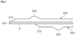
- FIG. 1 is a view illustrating an appearance of a general electrode for a secondary battery
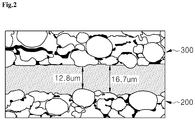
- FIG. 2 is a state in which a pressure is applied to a current collector of the general electrode for a secondary battery.
- FIG. 2 is a view illustrating a position at which a crack is generated in the current collector of the general electrode for a secondary battery
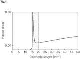
- FIG. 4 is a view illustrating a plastic strain of the current collector of the general electrode for a secondary battery.
- a first active material layer 200 including a first inclined portion 210 and a first protruding portion 220 is provided on one surface of a current collector 100 extending in one direction.
- a second active material layer 300 including a second inclined portion 310 and a second protruding portion 320 is provided on the other surface of the current collector 100.
- the inclined portion represents a drag area formed on an end of a coated area in a sharp manner
- the protruding portion represents a balcony area formed on a position spaced a predetermined distance from the inclined portion in a protruding manner.
- a non-coated portion N, on which the first active material layer 200 is not supplied is provided on one surface of the current collector 100 to ensure stability according to winding.
- the non-coated portion N, on which the first active material layer 200 is not supplied is provided on the one surface of the current collector 100, and the second active material layer 300 is provided on the other surface of the current collector 100, a second protruding portion 320 of the second active material layer 300 is positioned on an area directly opposite to the first inclined portion 210 of the first active material layer 200.
- the current collector 100 maintains a thickness of approximately 16.7 ⁇ m between the first active material layer 200 and the second active material layer 300, the current collector 100 has a thickness of approximately 12.8 ⁇ m at the area, which is directly opposite to the first inclined portion 210 of the first active material layer 200 and on which the second protruding portion 320 of the second active material layer 300 is positioned.
- the non-coated portion N, on which the first active material layer 200 is not supplied is provided by a predetermined length (a length of approximately 13 mm in FIGS. 2 to 4 ) from the end of the current collector 100 on the one surface of the current collector 100.
- a predetermined length a length of approximately 13 mm in FIGS. 2 to 4
- the thickness of the electrode including the first active material layer 200 and the current collector 100 continues to increase from a point at which the electrode length, i.e., a length from the end of the current collector, is approximately 0, the non-coated portion is passed, and then the first active material layer 200, which is initiated with the first inclined portion 210, is provided on an area in which the second protruding portion 320 of the second active material layer 300 is positioned.
- the thickness of the electrode including the first active material layer 200, the current collector 100, and the second active material layer 300 remarkably increases at a point at which the electrode length including the non-coated portion N and a boundary of the second active material layer 300 is approximately 15 mm to approximately 20 mm.
- an equivalent plastic stain (PEEQ) of the current collector 100 remarkably increases to have a peak value of approximately 0.06 or more at a position at which the length from the end of the current collector is approximately 15 mm to approximately 20 mm due to the local increase of the rolling ratio.
- PEEQ equivalent plastic stain
- the electrode for a second battery, the method for manufacturing the same, and the electrode assembly in accordance with an exemplary embodiment suggest a technical feature capable of preventing the deformation of the current collector 100 by relieving the pressure applied to the current collector 100 and preventing the crack from being generated in advance while the electrode is wound in a process of manufacturing the electrode.
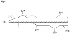
- FIG. 5 is a view illustrating an appearance of an electrode for a secondary battery in accordance with an exemplary embodiment
- FIG. 6 is a view illustrating an appearance of an electrode for a secondary battery in accordance with another exemplary embodiment.
- an electrode for a secondary battery in accordance with an exemplary embodiment includes: a current collector 100 extending in one direction, a first active material layer 200 provided on one surface of the current collector 100 and including a first inclined portion 210 and a first protruding portion 220; and a second active material layer 300 provided on the other surface of the current collector 100 and including a second inclined portion 310 and a second protruding portion 320.
- the second protruding portion 320 is controlled so as to be provided on a position on the second active material layer 300, which is not directly opposite to the first inclined portion 210 with respect to the current collector 100.
- first inclined portion 210 and the first protruding portion 220 are provided on one side of the first active material layer 200
- the second inclined portion 310 and the second protruding portion 320 are provided on one side of the second active material layer 300, which is disposed in the same direction as the one side of the first active material layer 200. That is, as exemplarily illustrated in FIGS. 5 and 6 , the first inclined portion 210 and the first protruding portion 220 may be provided on the left side of the first active material layer 200, and the second inclined portion 310 and the second protruding portion 320 may be provided on the left side of the second active material layer 300, which is the same direction as the above.
- a non-coated portion N, on which the first active material layer 200 is not supplied is provided on one surface of the current collector 100 to ensure stability according to winding.
- the non-coated portion N, on which the first active material layer 200 is not supplied is provided on the one surface of the current collector 100, and the second active material layer 300 is provided on the other surface of the current collector 100, a protruding portion 320 of the second active material layer 300 is positioned on an area directly opposite to the first inclined portion 210 of the first active material layer 200.
- a rolling ratio locally increases, and a crack is generated.
- the second protruding portion 320 of the second active material layer 300 is controlled so as to be provided on a position on the second active material layer 300, which is not directly opposite to the first inclined portion 210 with respect to the current collector 100.
- the non-coated portion N may be provided to have a length of approximately 10 mm to approximately 20 mm in an extension direction of the current collector 100.
- the first inclined portion 210 represents a drag area provided to have a sharp shape on an end of the first active material layer 200
- the second inclined portion 310 represents a drag area provided to have a sharp shape on an end of the second active material layer 300.
- the second protruding portion 320 of the second active material layer 300 when the second protruding portion 320 of the second active material layer 300 is provided on a position that is not directly opposite to the first inclined portion 210 of the first active material layer 200 with respect to the current collector 100, the end of the first active material layer 200, i.e., the first inclined portion 210, is not remarkably varied in thickness.
- the electrode thickness on the area of the first inclined portion 210 may be varied by only the first inclined portion 210, and thus the electrode thickness may be prevented from being remarkably varied.
- FIG. 5 is a view illustrating an appearance of the electrode for a secondary battery in accordance with an exemplary embodiment.
- the second protruding portion 320 of the second active material layer 300 is transferred from the position directly opposite to the inclined portion 210 to an end side (left side on the drawing) of the current collector 100. Accordingly, as the electrode thickness in the area directly opposite to the first inclined portion 210 is prevented from being remarkably varied, and, as a result, the local rolling ratio may be prevented from remarkably increasing by the first inclined portion 210 and the second protruding portion 320, the deformation and the crack may be prevented from occurring on the current collector 100 while the electrode is wound in advance.
- FIG. 6 is a view illustrating an appearance of an electrode for a secondary battery in accordance with another exemplary embodiment.
- the second protruding portion 320 of the second active material layer 300 moves from the position directly opposite to the first inclined portion 210 to an opposite side (right side on the drawing) of the end of the current collector 100. That is, the second protruding portion 320 is spaced a predetermined distance from the second inclined portion 310.
- the electrode thickness in the area directly opposite to the first inclined portion 210 is prevented from being remarkably varied, and, as a result, the local rolling ratio is prevented from remarkably increasing by the first inclined portion 210 and the second protruding portion 320, the deformation and the crack may be prevented from occurring on the current collector 100 in advance.
- a configuration, in which the position of the second protruding portion 320 moves on the second active material layer, will be described below in detail in relation to the method for manufacturing the electrode for a secondary battery.
- a method for manufacturing an electrode for a secondary battery in accordance with an exemplary embodiment includes: a process of preparing the current collector 100 in which the first active material layer 200 including the first inclined portion 210 and the first protruding portion 220 is provided on one surface thereof; a process of transferring the current collector 100 in one direction; and a process of forming the second active material layer 300 including the second inclined portion 310 and the second protruding portion 320 by applying the second active material on the other surface of the current collector 100.
- the second active material layer 300 is controlled in position so that the second protruding portion 320 is provided on a position that is not directly opposite to the first inclined portion 210 with respect to the current collector 100.
- a coating device for forming the active material layer includes: a supply roll for unwinding the current collector 100, which is wound in a roll type, to continuously supply the unwound current collector in one direction; a coating die for applying active material slurry, which is supplied from an external active material slurry supply source, to the current collector 100, which continuously moves in the one direction; a dryer for forming the active material layer on the current collector 100 by drying the active material slurry applied on the current collector 100; and a withdrawal roll for withdrawing the current collector 100 in a rolled state by winding the current collector 100 on which the active material is provided.
- the process of preparing the current collector 100 in which the first active material layer 200 including the first inclined portion 210 and the first protruding portion 220 is formed on one surface thereof, is performed by the above-described coating device.
- the active material slurry is applied on one surface of the current collector 100 and then dried to form the first active material layer 200.
- the first active material layer 200 is formed on a position spaced by a distance of approximately 10 mm to approximately 20 mm from the end of the current collector 100, so that the non-coated portion N is formed on one surface of the current collector 100, the first inclined portion 210 is formed on the end of the first active material layer 200, and the first protruding portion 220 is formed on a position spaced by a predetermined distance from the first inclined portion 210.
- the first active material layer 200 is formed on the one surface of the current collector 100, and then the second active material layer 300 is formed on the other surface of the current collector 100 by the above-described coating device.
- the above-described process includes: a process of transferring the current collector 100 in one direction; and a process of forming the second active material layer 300 including the second inclined portion 310 and the second protruding portion 320 by applying the second active material, i.e., the second active material slurry, on the other surface of the current collector 100.
- the process of transferring the current collector 100 in one direction and the process of forming the second active material layer 300 of the other surface of the current collector 100 may be performed by the above-described coating device.
- the method for manufacturing the electrode for a secondary battery in accordance with an exemplary embodiment controls the second protruding portion 320 of the second active material layer 300 is formed on a position that is not directly opposite to the first inclined portion 210 with respect to the current collector 100 in the process of forming the second active material layer 300.
- the above-described position control of the second protruding portion 320 may be performed by regulating an application pressure of the second active material layer 300. That is, when the second active material layer 300 is formed on the other surface of the current collector 100, the position of the second protruding portion 320 may be controlled by changing the application pressure of the coating die that supplies the second active material slurry.
- the second protruding portion 320 of the second active material layer 300 may be transferred from the position directly opposite to the first inclined portion 210 to the end side (left side on the drawing) of the current collector 100.
- the second protruding portion 320 of the second active material layer 300 may be transferred from the position directly opposite to the first inclined portion 210 to an opposite side (right side on the drawing) of the end of the current collector 100.
- the position of the second protruding portion 320 may be adjusted by locally regulating the application pressure of the coating die for supplying the second active material slurry.
- the second protruding portion 320 may be controlled to be formed on the position that is not directly opposite to the first inclined portion 210 with respect to the current collector 100.
- the regulation of the application pressure of the coating die may be performed by controlling a valve for supplying the second active material slurry.
- the coating die may include: an accommodation part for accommodating the second active material slurry; a nozzle for discharging the second active material slurry; and a valve for regulating an inner pressure of the accommodation part.
- the valve may be a rod that is installed in the accommodation part in an ascending/descending manner to press the second active material slurry accommodated in the accommodation part.
- the valve may be driven by a motor.
- an electric motor which is operated by an electric signal, may be used for the above-described motor for driving the valve, a voice coil motor (VCM) is preferred to precisely regulate the inner pressure of the accommodation part.
- VCM voice coil motor
- the voice coil motor is not varied in force according to positions because a coil thereof is operated in a uniform magnetic field and used for a micro-operation of several micrometers or less. Also, the voice coil motor may precisely regulate the application pressure of the coating die for supplying the second active material slurry because of a fast response speed thereof.
- the position control of the second protruding portion 320 may be performed by regulating the transfer speed of the current collector 100 when the second active material layer 300 is applied. That is, when the second active material layer 300 is formed on the other surface of the current collector 100, the position of the second protruding portion 320 may be controlled by changing a rotation speed of each of the supply roll and the winding roll, which transfer the current collector 100 in one direction, and regulating the transfer speed of the current collector 100.
- the second protruding portion 320 of the second active material layer 300 is transferred from the position directly opposite to the first inclined portion 210 to the end side (left side on the drawing) of the current collector 100. Also, when the transfer speed of the current collector 100 increases in the process of forming the second active material layer 300, the second protruding portion 320 of the second active material layer 300 is transferred from the position directly opposite to the first inclined portion 210 to the opposite side (right side on the drawing) of the end of the current collector 100. Furthermore, as the transfer speed of the current collector 100 is locally changed, the position of the second protruding portion 320 may be adjusted.
- the second protruding portion 320 may be controlled to be formed on the position that is not directly opposite to the first inclined portion 210 with respect to the current collector 100 by increasing the transfer speed of the current collector at the position directly opposite to the first inclined portion 210.
- the above-described electrode in accordance with an exemplary embodiment may be used for a jellyroll-type electrode assembly. That is, as an electrode assembly in which a positive electrode, a negative electrode, and a separator disposed between the positive electrode and the negative electrode, at least one of the positive electrode and negative electrode may be the above-described electrode for a secondary battery.
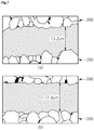
- FIG. 7 is a view illustrating a state in which a pressure is applied to the current collector in the electrode for a secondary battery in accordance with an exemplary embodiment.
- (a) of FIG. 7 illustrates a state in which a pressure is applied to the current collector 100 when the protruding portion 320 of the second active material layer 300 is disposed on the position directly opposite to the first inclined portion 210 of the first active material layer 200
- (b) of FIG. 7 illustrates a state in which a pressure is applied to the current collector 100 when the protruding portion 320 of the second active material layer 300 is not disposed on the position directly opposite to the first inclined portion 210 of the first active material layer 200.
- the protruding portion 320 of the second active material layer 300 has a width of approximately 8 mm and a height of approximately 8 ⁇ m, and the first inclined portion 210 of the first active material layer 200 has a thickness of approximately 20 ⁇ m from the current collector 100.
- the current collector 100 between the first active material layer 200 and the second active material layer 300 has a thickness of approximately 13.2 ⁇ m.
- the electrode for a secondary battery in accordance with an exemplary embodiment in (b) of FIG. 7 , as the current collector 100 has a thickness of approximately 17.5 ⁇ m, a pressure applied to the current collector 100 decreases, and accordingly the local rolling ratio is effectively reduced.
- FIG. 8 The above-described a plastic strain of the current collector 100 according to the thickness variation thereof is illustrated in FIG. 8 .
- a portion expressed by a dotted line represents the equivalent plastic strain (PEEQ) of the current collector 100 when the protruding portion 320 of the second active material layer 300 is disposed on the position directly opposite to the first inclined portion 210 of the first active material layer 200
- a portion expressed by a solid line represents the equivalent plastic strain (PEEQ) of the current collector 100 when the protruding portion 320 of the second active material layer 300 is not disposed on the position directly opposite to the first inclined portion 210 of the first active material layer 200.
- the peak value of the equivalent plastic strain (PEEQ) of the current collector 100 dramatically increases to have a value of approximately 0.06 or more in the length of approximately 10 mm to approximately 20 mm from the end of the current collector 100 due to increase in the local rolling ratio.
- PEEQ equivalent plastic strain
- the electrodes for a secondary battery may be manufactured with 0% failure rate, and thus a crack generated while the electrode is manufactured may be prevented in advance.
- the manufacturing method therefor, and the electrode assembly in accordance with an exemplary embodiment as the protruding portion of the second active material layer 300 is controlled to be formed on the position that is not directly opposite to the inclined portion of the first active material layer 200 with respect to the current collector 100, the pressure applied to the current collector 100 is relieved to prevent the current collector 100 from being deformed, and the crack generated while the electrode is manufactured may be prevented in advance.
- each of the first active material layer 200 and the second active material layer 300 which are formed on the both surface of the current collector 100, respectively, is controlled to prevent the thickness of the electrode from dramatically increasing, the electrode for a secondary battery having a uniform thickness may be achieved, and product safety, an economical efficiency, and a yield may be enhanced.
Landscapes
- Chemical & Material Sciences (AREA)
- Chemical Kinetics & Catalysis (AREA)
- Electrochemistry (AREA)
- General Chemical & Material Sciences (AREA)
- Engineering & Computer Science (AREA)
- Manufacturing & Machinery (AREA)
- Composite Materials (AREA)
- Materials Engineering (AREA)
- Battery Electrode And Active Subsutance (AREA)
- Secondary Cells (AREA)
Applications Claiming Priority (3)
| Application Number | Priority Date | Filing Date | Title |
|---|---|---|---|
| KR20170105613 | 2017-08-21 | ||
| KR1020180093108A KR102265849B1 (ko) | 2017-08-21 | 2018-08-09 | 이차 전지용 전극, 이의 제조 방법 및 전극 조립체 |
| PCT/KR2018/009533 WO2019039815A2 (ko) | 2017-08-21 | 2018-08-20 | 이차 전지용 전극, 이의 제조 방법 및 전극 조립체 |
Publications (3)
| Publication Number | Publication Date |
|---|---|
| EP3595047A2 true EP3595047A2 (de) | 2020-01-15 |
| EP3595047A4 EP3595047A4 (de) | 2020-01-22 |
| EP3595047B1 EP3595047B1 (de) | 2024-12-18 |
Family
ID=65759899
Family Applications (1)
| Application Number | Title | Priority Date | Filing Date |
|---|---|---|---|
| EP18849036.1A Active EP3595047B1 (de) | 2017-08-21 | 2018-08-20 | Sekundärbatterieelektrode, herstellungsverfahren dafür und elektrodenanordnung |
Country Status (7)
| Country | Link |
|---|---|
| US (1) | US11539044B2 (de) |
| EP (1) | EP3595047B1 (de) |
| JP (1) | JP7047202B2 (de) |
| KR (1) | KR102265849B1 (de) |
| CN (1) | CN110495019B (de) |
| ES (1) | ES3000912T3 (de) |
| HU (1) | HUE069709T2 (de) |
Families Citing this family (3)
| Publication number | Priority date | Publication date | Assignee | Title |
|---|---|---|---|---|
| KR102516225B1 (ko) | 2019-04-08 | 2023-03-30 | 주식회사 엘지에너지솔루션 | 이차전지 및 그의 제조방법 |
| KR102563299B1 (ko) | 2020-12-30 | 2023-08-04 | 주식회사 에스에프에이 | 전극 모니터링 장치 및 방법 |
| KR102884061B1 (ko) * | 2021-05-04 | 2025-11-07 | 주식회사 엘지에너지솔루션 | 전극의 제조 장치, 전극의 제조 방법, 및 그에 의해 제조된 전극 |
Family Cites Families (21)
| Publication number | Priority date | Publication date | Assignee | Title |
|---|---|---|---|---|
| JPH11265707A (ja) | 1998-03-16 | 1999-09-28 | Mitsubishi Cable Ind Ltd | 電池の電極及びこの電極の製造方法 |
| JP4284760B2 (ja) | 1999-06-29 | 2009-06-24 | パナソニック株式会社 | 負極用電極板およびその負極用電極板を用いた非水電解液二次電池 |
| JP4043956B2 (ja) * | 2003-01-08 | 2008-02-06 | 大日本印刷株式会社 | 電池用電極板の製造方法 |
| KR100601550B1 (ko) | 2004-07-28 | 2006-07-19 | 삼성에스디아이 주식회사 | 리튬이온 이차 전지 |
| KR100624936B1 (ko) | 2004-10-28 | 2006-09-15 | 삼성에스디아이 주식회사 | 이차 전지 |
| KR101142589B1 (ko) | 2006-11-15 | 2012-05-10 | 파나소닉 주식회사 | 비수계 이차전지용 집전체, 및 그것을 사용한 비수계 이차전지용 전극판 및 비수계 이차전지 |
| JP5540570B2 (ja) * | 2008-09-26 | 2014-07-02 | 日産自動車株式会社 | 双極型二次電池、双極型二次電池の製造方法、双極型電極、双極型電極の製造方法、組電池 |
| JP5471018B2 (ja) | 2009-04-30 | 2014-04-16 | 日産自動車株式会社 | 双極型電極の製造方法、双極型電極、双極型二次電池の製造方法、双極型二次電池、組電池、および車両 |
| JP2011138675A (ja) | 2009-12-28 | 2011-07-14 | Panasonic Corp | 非水系二次電池用電極群およびこれを用いた非水系二次電池 |
| JP2011146219A (ja) | 2010-01-14 | 2011-07-28 | Panasonic Corp | 非水系二次電池用電極群およびこれを用いた非水系二次電池 |
| JP5541509B2 (ja) * | 2010-06-28 | 2014-07-09 | Necエナジーデバイス株式会社 | 集電体電極板の製造方法 |
| KR20120095122A (ko) * | 2011-02-18 | 2012-08-28 | 주식회사 엘지화학 | 전극 조립체 및 이를 이용한 이차 전지 |
| WO2014034708A1 (ja) | 2012-08-29 | 2014-03-06 | シャープ株式会社 | 電極板および二次電池 |
| JP2014120293A (ja) | 2012-12-14 | 2014-06-30 | Toyota Industries Corp | 電極の製造方法 |
| JP6381045B2 (ja) * | 2013-07-31 | 2018-08-29 | Necエナジーデバイス株式会社 | 二次電池 |
| US10290903B2 (en) | 2013-11-12 | 2019-05-14 | Lg Chem, Ltd. | Jellyroll-type electrode assembly and secondary battery comprising the same |
| KR101675950B1 (ko) | 2014-05-08 | 2016-11-14 | 주식회사 엘지화학 | 교번 배열된 무지부와 코팅부를 포함하고 있는 플렉서블 전극조립체 및 그것을 포함하는 전지셀 |
| KR101736545B1 (ko) | 2014-10-31 | 2017-05-16 | 주식회사 엘지화학 | 전극 조립체 |
| JP6372334B2 (ja) | 2014-12-11 | 2018-08-15 | 株式会社豊田自動織機 | 電極の製造装置及び電極の製造方法 |
| KR101877101B1 (ko) * | 2015-07-28 | 2018-08-09 | 주식회사 엘지화학 | 전극 활물질 슬러리 코팅 장치 및 방법 |
| KR102484265B1 (ko) | 2015-12-22 | 2023-01-02 | 삼성에스디아이 주식회사 | 전극 조립체 및 이를 이용한 이차 전지 |
-
2018
- 2018-08-09 KR KR1020180093108A patent/KR102265849B1/ko active Active
- 2018-08-20 ES ES18849036T patent/ES3000912T3/es active Active
- 2018-08-20 HU HUE18849036A patent/HUE069709T2/hu unknown
- 2018-08-20 US US16/605,491 patent/US11539044B2/en active Active
- 2018-08-20 CN CN201880024191.1A patent/CN110495019B/zh active Active
- 2018-08-20 EP EP18849036.1A patent/EP3595047B1/de active Active
- 2018-08-20 JP JP2019549523A patent/JP7047202B2/ja active Active
Also Published As
| Publication number | Publication date |
|---|---|
| KR20190020618A (ko) | 2019-03-04 |
| EP3595047B1 (de) | 2024-12-18 |
| JP7047202B2 (ja) | 2022-04-05 |
| CN110495019B (zh) | 2022-11-29 |
| EP3595047A4 (de) | 2020-01-22 |
| US11539044B2 (en) | 2022-12-27 |
| CN110495019A (zh) | 2019-11-22 |
| ES3000912T3 (es) | 2025-03-04 |
| JP2020510977A (ja) | 2020-04-09 |
| HUE069709T2 (hu) | 2025-04-28 |
| US20210126249A1 (en) | 2021-04-29 |
| KR102265849B1 (ko) | 2021-06-16 |
Similar Documents
| Publication | Publication Date | Title |
|---|---|---|
| KR101650417B1 (ko) | 양극 집전체에 간헐적 무지부가 형성된 젤리 롤 형태 전극 조립체를 가진 이차전지 | |
| EP3595047B1 (de) | Sekundärbatterieelektrode, herstellungsverfahren dafür und elektrodenanordnung | |
| KR101639209B1 (ko) | 개선된 구조의 젤리-롤 형 전극 조립체 및 이를 포함하는 이차 전지 | |
| US10500605B2 (en) | Apparatus and method for coating electrode active material slurry | |
| US9437898B2 (en) | Secondary battery including plurality of electrode assemblies | |
| EP4297115B1 (de) | Elektrodentrocknungsvorrichtung, elektrodenherstellungssystem mit dieser vorrichtung, verfahren zur herstellung der elektrode und nach diesem verfahren hergestellte elektrode | |
| EP4322241A1 (de) | Elektrodenplattenerweiterungsvorrichtung und elektrodenplattenherstellungsvorrichtung | |
| KR101651516B1 (ko) | 개선된 구조의 젤리-롤 형 전극 조립체 및 이를 포함하는 이차 전지 | |
| CN102299341A (zh) | 表面凹凸处理金属箔锂离子电池用极板及其制造方法 | |
| KR102405345B1 (ko) | 단위셀 및 그 제조방법 | |
| KR20220122400A (ko) | 원통형 전극 조립체의 고정 장치 | |
| KR102690895B1 (ko) | 전극조립체의 제조방법 및 제조장치 | |
| CN217740568U (zh) | 极片、压痕机构、分切装置、电池单体、电池及用电装置 | |
| US20260034559A1 (en) | Apparatus and method for manufacturing electrode plate of secondary battery including substrate shrinkage prevention unit | |
| CN221201256U (zh) | 补锂装置 | |
| EP4250386B1 (de) | Kalanderwalzen für eine kalanderwalzenpresse zur herstellung einer trockenelektrode | |
| KR102888609B1 (ko) | 전지의 제조 방법 | |
| US20250391884A1 (en) | Apparatus and method for manufacturing an electrode for a secondary battery | |
| EP4203127B1 (de) | Einzelzellentransfervorrichtung | |
| CN115152088B (zh) | 电化学装置以及电子装置 | |
| US20260081132A1 (en) | Apparatus and method for manufacturing electrode plate of secondary battery | |
| CN215680755U (zh) | 锂离子电池和车辆 | |
| KR20260064053A (ko) | 전극시트 권취장치 및 이를 이용한 전극시트 권취방법 | |
| CN119542565A (zh) | 电极组件、电池单体、电池装置及用电设备 | |
| CN122003732A (zh) | 电极、该电极的制造方法以及用于涂覆活性材料的槽型模具 |
Legal Events
| Date | Code | Title | Description |
|---|---|---|---|
| STAA | Information on the status of an ep patent application or granted ep patent |
Free format text: STATUS: THE INTERNATIONAL PUBLICATION HAS BEEN MADE |
|
| PUAI | Public reference made under article 153(3) epc to a published international application that has entered the european phase |
Free format text: ORIGINAL CODE: 0009012 |
|
| STAA | Information on the status of an ep patent application or granted ep patent |
Free format text: STATUS: REQUEST FOR EXAMINATION WAS MADE |
|
| 17P | Request for examination filed |
Effective date: 20191011 |
|
| AK | Designated contracting states |
Kind code of ref document: A2 Designated state(s): AL AT BE BG CH CY CZ DE DK EE ES FI FR GB GR HR HU IE IS IT LI LT LU LV MC MK MT NL NO PL PT RO RS SE SI SK SM TR |
|
| AX | Request for extension of the european patent |
Extension state: BA ME |
|
| A4 | Supplementary search report drawn up and despatched |
Effective date: 20200103 |
|
| RIC1 | Information provided on ipc code assigned before grant |
Ipc: H01M 4/04 20060101ALI20191218BHEP Ipc: H01M 4/02 20060101AFI20191218BHEP Ipc: H01M 10/04 20060101ALI20191218BHEP |
|
| DAV | Request for validation of the european patent (deleted) | ||
| DAX | Request for extension of the european patent (deleted) | ||
| RAP1 | Party data changed (applicant data changed or rights of an application transferred) |
Owner name: LG ENERGY SOLUTION LTD. |
|
| RAP3 | Party data changed (applicant data changed or rights of an application transferred) |
Owner name: LG ENERGY SOLUTION, LTD. |
|
| STAA | Information on the status of an ep patent application or granted ep patent |
Free format text: STATUS: EXAMINATION IS IN PROGRESS |
|
| 17Q | First examination report despatched |
Effective date: 20240206 |
|
| RIC1 | Information provided on ipc code assigned before grant |
Ipc: H01M 10/0525 20100101ALI20240809BHEP Ipc: H01M 10/0587 20100101ALI20240809BHEP Ipc: H01M 10/04 20060101ALI20240809BHEP Ipc: H01M 4/04 20060101ALI20240809BHEP Ipc: H01M 4/02 20060101AFI20240809BHEP |
|
| GRAP | Despatch of communication of intention to grant a patent |
Free format text: ORIGINAL CODE: EPIDOSNIGR1 |
|
| STAA | Information on the status of an ep patent application or granted ep patent |
Free format text: STATUS: GRANT OF PATENT IS INTENDED |
|
| INTG | Intention to grant announced |
Effective date: 20240923 |
|
| GRAS | Grant fee paid |
Free format text: ORIGINAL CODE: EPIDOSNIGR3 |
|
| GRAA | (expected) grant |
Free format text: ORIGINAL CODE: 0009210 |
|
| STAA | Information on the status of an ep patent application or granted ep patent |
Free format text: STATUS: THE PATENT HAS BEEN GRANTED |
|
| P01 | Opt-out of the competence of the unified patent court (upc) registered |
Free format text: CASE NUMBER: APP_56670/2024 Effective date: 20241017 |
|
| AK | Designated contracting states |
Kind code of ref document: B1 Designated state(s): AL AT BE BG CH CY CZ DE DK EE ES FI FR GB GR HR HU IE IS IT LI LT LU LV MC MK MT NL NO PL PT RO RS SE SI SK SM TR |
|
| REG | Reference to a national code |
Ref country code: CH Ref legal event code: EP |
|
| REG | Reference to a national code |
Ref country code: DE Ref legal event code: R096 Ref document number: 602018077796 Country of ref document: DE |
|
| REG | Reference to a national code |
Ref country code: IE Ref legal event code: FG4D |
|
| REG | Reference to a national code |
Ref country code: ES Ref legal event code: FG2A Ref document number: 3000912 Country of ref document: ES Kind code of ref document: T3 Effective date: 20250304 |
|
| REG | Reference to a national code |
Ref country code: LT Ref legal event code: MG9D |
|
| PG25 | Lapsed in a contracting state [announced via postgrant information from national office to epo] |
Ref country code: HR Free format text: LAPSE BECAUSE OF FAILURE TO SUBMIT A TRANSLATION OF THE DESCRIPTION OR TO PAY THE FEE WITHIN THE PRESCRIBED TIME-LIMIT Effective date: 20241218 |
|
| PG25 | Lapsed in a contracting state [announced via postgrant information from national office to epo] |
Ref country code: FI Free format text: LAPSE BECAUSE OF FAILURE TO SUBMIT A TRANSLATION OF THE DESCRIPTION OR TO PAY THE FEE WITHIN THE PRESCRIBED TIME-LIMIT Effective date: 20241218 |
|
| PG25 | Lapsed in a contracting state [announced via postgrant information from national office to epo] |
Ref country code: BG Free format text: LAPSE BECAUSE OF FAILURE TO SUBMIT A TRANSLATION OF THE DESCRIPTION OR TO PAY THE FEE WITHIN THE PRESCRIBED TIME-LIMIT Effective date: 20241218 |
|
| PG25 | Lapsed in a contracting state [announced via postgrant information from national office to epo] |
Ref country code: NO Free format text: LAPSE BECAUSE OF FAILURE TO SUBMIT A TRANSLATION OF THE DESCRIPTION OR TO PAY THE FEE WITHIN THE PRESCRIBED TIME-LIMIT Effective date: 20250318 |
|
| REG | Reference to a national code |
Ref country code: NL Ref legal event code: MP Effective date: 20241218 |
|
| PG25 | Lapsed in a contracting state [announced via postgrant information from national office to epo] |
Ref country code: LV Free format text: LAPSE BECAUSE OF FAILURE TO SUBMIT A TRANSLATION OF THE DESCRIPTION OR TO PAY THE FEE WITHIN THE PRESCRIBED TIME-LIMIT Effective date: 20241218 Ref country code: GR Free format text: LAPSE BECAUSE OF FAILURE TO SUBMIT A TRANSLATION OF THE DESCRIPTION OR TO PAY THE FEE WITHIN THE PRESCRIBED TIME-LIMIT Effective date: 20250319 |
|
| REG | Reference to a national code |
Ref country code: HU Ref legal event code: AG4A Ref document number: E069709 Country of ref document: HU |
|
| PG25 | Lapsed in a contracting state [announced via postgrant information from national office to epo] |
Ref country code: RS Free format text: LAPSE BECAUSE OF FAILURE TO SUBMIT A TRANSLATION OF THE DESCRIPTION OR TO PAY THE FEE WITHIN THE PRESCRIBED TIME-LIMIT Effective date: 20250318 |
|
| PG25 | Lapsed in a contracting state [announced via postgrant information from national office to epo] |
Ref country code: NL Free format text: LAPSE BECAUSE OF FAILURE TO SUBMIT A TRANSLATION OF THE DESCRIPTION OR TO PAY THE FEE WITHIN THE PRESCRIBED TIME-LIMIT Effective date: 20241218 |
|
| REG | Reference to a national code |
Ref country code: AT Ref legal event code: MK05 Ref document number: 1752978 Country of ref document: AT Kind code of ref document: T Effective date: 20241218 |
|
| PG25 | Lapsed in a contracting state [announced via postgrant information from national office to epo] |
Ref country code: SM Free format text: LAPSE BECAUSE OF FAILURE TO SUBMIT A TRANSLATION OF THE DESCRIPTION OR TO PAY THE FEE WITHIN THE PRESCRIBED TIME-LIMIT Effective date: 20241218 |
|
| PG25 | Lapsed in a contracting state [announced via postgrant information from national office to epo] |
Ref country code: PL Free format text: LAPSE BECAUSE OF FAILURE TO SUBMIT A TRANSLATION OF THE DESCRIPTION OR TO PAY THE FEE WITHIN THE PRESCRIBED TIME-LIMIT Effective date: 20241218 |
|
| PG25 | Lapsed in a contracting state [announced via postgrant information from national office to epo] |
Ref country code: IS Free format text: LAPSE BECAUSE OF FAILURE TO SUBMIT A TRANSLATION OF THE DESCRIPTION OR TO PAY THE FEE WITHIN THE PRESCRIBED TIME-LIMIT Effective date: 20250418 |
|
| PGFP | Annual fee paid to national office [announced via postgrant information from national office to epo] |
Ref country code: BE Payment date: 20250407 Year of fee payment: 8 |
|
| PG25 | Lapsed in a contracting state [announced via postgrant information from national office to epo] |
Ref country code: PT Free format text: LAPSE BECAUSE OF FAILURE TO SUBMIT A TRANSLATION OF THE DESCRIPTION OR TO PAY THE FEE WITHIN THE PRESCRIBED TIME-LIMIT Effective date: 20250421 |
|
| PG25 | Lapsed in a contracting state [announced via postgrant information from national office to epo] |
Ref country code: EE Free format text: LAPSE BECAUSE OF FAILURE TO SUBMIT A TRANSLATION OF THE DESCRIPTION OR TO PAY THE FEE WITHIN THE PRESCRIBED TIME-LIMIT Effective date: 20241218 |
|
| PG25 | Lapsed in a contracting state [announced via postgrant information from national office to epo] |
Ref country code: AT Free format text: LAPSE BECAUSE OF FAILURE TO SUBMIT A TRANSLATION OF THE DESCRIPTION OR TO PAY THE FEE WITHIN THE PRESCRIBED TIME-LIMIT Effective date: 20241218 Ref country code: RO Free format text: LAPSE BECAUSE OF FAILURE TO SUBMIT A TRANSLATION OF THE DESCRIPTION OR TO PAY THE FEE WITHIN THE PRESCRIBED TIME-LIMIT Effective date: 20241218 |
|
| PG25 | Lapsed in a contracting state [announced via postgrant information from national office to epo] |
Ref country code: SK Free format text: LAPSE BECAUSE OF FAILURE TO SUBMIT A TRANSLATION OF THE DESCRIPTION OR TO PAY THE FEE WITHIN THE PRESCRIBED TIME-LIMIT Effective date: 20241218 |
|
| PG25 | Lapsed in a contracting state [announced via postgrant information from national office to epo] |
Ref country code: CZ Free format text: LAPSE BECAUSE OF FAILURE TO SUBMIT A TRANSLATION OF THE DESCRIPTION OR TO PAY THE FEE WITHIN THE PRESCRIBED TIME-LIMIT Effective date: 20241218 |
|
| PG25 | Lapsed in a contracting state [announced via postgrant information from national office to epo] |
Ref country code: IT Free format text: LAPSE BECAUSE OF FAILURE TO SUBMIT A TRANSLATION OF THE DESCRIPTION OR TO PAY THE FEE WITHIN THE PRESCRIBED TIME-LIMIT Effective date: 20241218 |
|
| PG25 | Lapsed in a contracting state [announced via postgrant information from national office to epo] |
Ref country code: SE Free format text: LAPSE BECAUSE OF FAILURE TO SUBMIT A TRANSLATION OF THE DESCRIPTION OR TO PAY THE FEE WITHIN THE PRESCRIBED TIME-LIMIT Effective date: 20241218 |
|
| PGFP | Annual fee paid to national office [announced via postgrant information from national office to epo] |
Ref country code: HU Payment date: 20250827 Year of fee payment: 8 |
|
| REG | Reference to a national code |
Ref country code: DE Ref legal event code: R097 Ref document number: 602018077796 Country of ref document: DE |
|
| PGFP | Annual fee paid to national office [announced via postgrant information from national office to epo] |
Ref country code: ES Payment date: 20250911 Year of fee payment: 8 |
|
| PG25 | Lapsed in a contracting state [announced via postgrant information from national office to epo] |
Ref country code: DK Free format text: LAPSE BECAUSE OF FAILURE TO SUBMIT A TRANSLATION OF THE DESCRIPTION OR TO PAY THE FEE WITHIN THE PRESCRIBED TIME-LIMIT Effective date: 20241218 |
|
| PGFP | Annual fee paid to national office [announced via postgrant information from national office to epo] |
Ref country code: DE Payment date: 20250721 Year of fee payment: 8 |
|
| PGFP | Annual fee paid to national office [announced via postgrant information from national office to epo] |
Ref country code: GB Payment date: 20250722 Year of fee payment: 8 |
|
| PGFP | Annual fee paid to national office [announced via postgrant information from national office to epo] |
Ref country code: FR Payment date: 20250725 Year of fee payment: 8 |
|
| PLBE | No opposition filed within time limit |
Free format text: ORIGINAL CODE: 0009261 |
|
| STAA | Information on the status of an ep patent application or granted ep patent |
Free format text: STATUS: NO OPPOSITION FILED WITHIN TIME LIMIT |
|
| REG | Reference to a national code |
Ref country code: CH Ref legal event code: L10 Free format text: ST27 STATUS EVENT CODE: U-0-0-L10-L00 (AS PROVIDED BY THE NATIONAL OFFICE) Effective date: 20251029 |
|
| 26N | No opposition filed |
Effective date: 20250919 |
|
| REG | Reference to a national code |
Ref country code: CH Ref legal event code: H13 Free format text: ST27 STATUS EVENT CODE: U-0-0-H10-H13 (AS PROVIDED BY THE NATIONAL OFFICE) Effective date: 20260324 |
|
| PG25 | Lapsed in a contracting state [announced via postgrant information from national office to epo] |
Ref country code: MC Free format text: LAPSE BECAUSE OF FAILURE TO SUBMIT A TRANSLATION OF THE DESCRIPTION OR TO PAY THE FEE WITHIN THE PRESCRIBED TIME-LIMIT Effective date: 20241218 |
|
| PG25 | Lapsed in a contracting state [announced via postgrant information from national office to epo] |
Ref country code: LU Free format text: LAPSE BECAUSE OF NON-PAYMENT OF DUE FEES Effective date: 20250820 |
|
| PG25 | Lapsed in a contracting state [announced via postgrant information from national office to epo] |
Ref country code: CH Free format text: LAPSE BECAUSE OF NON-PAYMENT OF DUE FEES Effective date: 20250831 |