EP3594650B1 - Pneumatisch-basierter taktiler sensor - Google Patents
Pneumatisch-basierter taktiler sensor Download PDFInfo
- Publication number
- EP3594650B1 EP3594650B1 EP17899762.3A EP17899762A EP3594650B1 EP 3594650 B1 EP3594650 B1 EP 3594650B1 EP 17899762 A EP17899762 A EP 17899762A EP 3594650 B1 EP3594650 B1 EP 3594650B1
- Authority
- EP
- European Patent Office
- Prior art keywords
- pneumatic
- sensor
- unit
- tactile sense
- tactile
- Prior art date
- Legal status (The legal status is an assumption and is not a legal conclusion. Google has not performed a legal analysis and makes no representation as to the accuracy of the status listed.)
- Active
Links
Images




Classifications
-
- G—PHYSICS
- G01—MEASURING; TESTING
- G01L—MEASURING FORCE, STRESS, TORQUE, WORK, MECHANICAL POWER, MECHANICAL EFFICIENCY, OR FLUID PRESSURE
- G01L1/00—Measuring force or stress, in general
- G01L1/02—Measuring force or stress, in general by hydraulic or pneumatic means
-
- G—PHYSICS
- G01—MEASURING; TESTING
- G01L—MEASURING FORCE, STRESS, TORQUE, WORK, MECHANICAL POWER, MECHANICAL EFFICIENCY, OR FLUID PRESSURE
- G01L1/00—Measuring force or stress, in general
- G01L1/14—Measuring force or stress, in general by measuring variations in capacitance or inductance of electrical elements, e.g. by measuring variations of frequency of electrical oscillators
-
- G—PHYSICS
- G01—MEASURING; TESTING
- G01L—MEASURING FORCE, STRESS, TORQUE, WORK, MECHANICAL POWER, MECHANICAL EFFICIENCY, OR FLUID PRESSURE
- G01L1/00—Measuring force or stress, in general
- G01L1/16—Measuring force or stress, in general using properties of piezoelectric devices
-
- G—PHYSICS
- G01—MEASURING; TESTING
- G01L—MEASURING FORCE, STRESS, TORQUE, WORK, MECHANICAL POWER, MECHANICAL EFFICIENCY, OR FLUID PRESSURE
- G01L1/00—Measuring force or stress, in general
- G01L1/20—Measuring force or stress, in general by measuring variations in ohmic resistance of solid materials or of electrically-conductive fluids; by making use of electrokinetic cells, i.e. liquid-containing cells wherein an electrical potential is produced or varied upon the application of stress
-
- G—PHYSICS
- G01—MEASURING; TESTING
- G01L—MEASURING FORCE, STRESS, TORQUE, WORK, MECHANICAL POWER, MECHANICAL EFFICIENCY, OR FLUID PRESSURE
- G01L5/00—Apparatus for, or methods of, measuring force, work, mechanical power, or torque, specially adapted for specific purposes
- G01L5/22—Apparatus for, or methods of, measuring force, work, mechanical power, or torque, specially adapted for specific purposes for measuring the force applied to control members, e.g. control members of vehicles, triggers
- G01L5/226—Apparatus for, or methods of, measuring force, work, mechanical power, or torque, specially adapted for specific purposes for measuring the force applied to control members, e.g. control members of vehicles, triggers to manipulators, e.g. the force due to gripping
-
- G—PHYSICS
- G01—MEASURING; TESTING
- G01L—MEASURING FORCE, STRESS, TORQUE, WORK, MECHANICAL POWER, MECHANICAL EFFICIENCY, OR FLUID PRESSURE
- G01L9/00—Measuring steady of quasi-steady pressure of fluid or fluent solid material by electric or magnetic pressure-sensitive elements; Transmitting or indicating the displacement of mechanical pressure-sensitive elements, used to measure the steady or quasi-steady pressure of a fluid or fluent solid material, by electric or magnetic means
- G01L9/0041—Transmitting or indicating the displacement of flexible diaphragms
- G01L9/007—Transmitting or indicating the displacement of flexible diaphragms using variations in inductance
-
- G—PHYSICS
- G01—MEASURING; TESTING
- G01L—MEASURING FORCE, STRESS, TORQUE, WORK, MECHANICAL POWER, MECHANICAL EFFICIENCY, OR FLUID PRESSURE
- G01L9/00—Measuring steady of quasi-steady pressure of fluid or fluent solid material by electric or magnetic pressure-sensitive elements; Transmitting or indicating the displacement of mechanical pressure-sensitive elements, used to measure the steady or quasi-steady pressure of a fluid or fluent solid material, by electric or magnetic means
- G01L9/14—Measuring steady of quasi-steady pressure of fluid or fluent solid material by electric or magnetic pressure-sensitive elements; Transmitting or indicating the displacement of mechanical pressure-sensitive elements, used to measure the steady or quasi-steady pressure of a fluid or fluent solid material, by electric or magnetic means involving the displacement of magnets, e.g. electromagnets
-
- G—PHYSICS
- G01—MEASURING; TESTING
- G01L—MEASURING FORCE, STRESS, TORQUE, WORK, MECHANICAL POWER, MECHANICAL EFFICIENCY, OR FLUID PRESSURE
- G01L1/00—Measuring force or stress, in general
- G01L1/12—Measuring force or stress, in general by measuring variations in the magnetic properties of materials resulting from the application of stress
-
- G—PHYSICS
- G01—MEASURING; TESTING
- G01L—MEASURING FORCE, STRESS, TORQUE, WORK, MECHANICAL POWER, MECHANICAL EFFICIENCY, OR FLUID PRESSURE
- G01L1/00—Measuring force or stress, in general
- G01L1/12—Measuring force or stress, in general by measuring variations in the magnetic properties of materials resulting from the application of stress
- G01L1/122—Measuring force or stress, in general by measuring variations in the magnetic properties of materials resulting from the application of stress by using permanent magnets
-
- G—PHYSICS
- G01—MEASURING; TESTING
- G01L—MEASURING FORCE, STRESS, TORQUE, WORK, MECHANICAL POWER, MECHANICAL EFFICIENCY, OR FLUID PRESSURE
- G01L1/00—Measuring force or stress, in general
- G01L1/12—Measuring force or stress, in general by measuring variations in the magnetic properties of materials resulting from the application of stress
- G01L1/127—Measuring force or stress, in general by measuring variations in the magnetic properties of materials resulting from the application of stress by using inductive means
-
- G—PHYSICS
- G01—MEASURING; TESTING
- G01L—MEASURING FORCE, STRESS, TORQUE, WORK, MECHANICAL POWER, MECHANICAL EFFICIENCY, OR FLUID PRESSURE
- G01L5/00—Apparatus for, or methods of, measuring force, work, mechanical power, or torque, specially adapted for specific purposes
- G01L5/16—Apparatus for, or methods of, measuring force, work, mechanical power, or torque, specially adapted for specific purposes for measuring several components of force
- G01L5/164—Apparatus for, or methods of, measuring force, work, mechanical power, or torque, specially adapted for specific purposes for measuring several components of force using variations in inductance
-
- G—PHYSICS
- G01—MEASURING; TESTING
- G01L—MEASURING FORCE, STRESS, TORQUE, WORK, MECHANICAL POWER, MECHANICAL EFFICIENCY, OR FLUID PRESSURE
- G01L5/00—Apparatus for, or methods of, measuring force, work, mechanical power, or torque, specially adapted for specific purposes
- G01L5/16—Apparatus for, or methods of, measuring force, work, mechanical power, or torque, specially adapted for specific purposes for measuring several components of force
- G01L5/169—Apparatus for, or methods of, measuring force, work, mechanical power, or torque, specially adapted for specific purposes for measuring several components of force using magnetic means
-
- G—PHYSICS
- G01—MEASURING; TESTING
- G01L—MEASURING FORCE, STRESS, TORQUE, WORK, MECHANICAL POWER, MECHANICAL EFFICIENCY, OR FLUID PRESSURE
- G01L5/00—Apparatus for, or methods of, measuring force, work, mechanical power, or torque, specially adapted for specific purposes
- G01L5/22—Apparatus for, or methods of, measuring force, work, mechanical power, or torque, specially adapted for specific purposes for measuring the force applied to control members, e.g. control members of vehicles, triggers
-
- G—PHYSICS
- G01—MEASURING; TESTING
- G01L—MEASURING FORCE, STRESS, TORQUE, WORK, MECHANICAL POWER, MECHANICAL EFFICIENCY, OR FLUID PRESSURE
- G01L5/00—Apparatus for, or methods of, measuring force, work, mechanical power, or torque, specially adapted for specific purposes
- G01L5/22—Apparatus for, or methods of, measuring force, work, mechanical power, or torque, specially adapted for specific purposes for measuring the force applied to control members, e.g. control members of vehicles, triggers
- G01L5/226—Apparatus for, or methods of, measuring force, work, mechanical power, or torque, specially adapted for specific purposes for measuring the force applied to control members, e.g. control members of vehicles, triggers to manipulators, e.g. the force due to gripping
- G01L5/228—Apparatus for, or methods of, measuring force, work, mechanical power, or torque, specially adapted for specific purposes for measuring the force applied to control members, e.g. control members of vehicles, triggers to manipulators, e.g. the force due to gripping using tactile array force sensors
-
- G—PHYSICS
- G06—COMPUTING OR CALCULATING; COUNTING
- G06F—ELECTRIC DIGITAL DATA PROCESSING
- G06F3/00—Input arrangements for transferring data to be processed into a form capable of being handled by the computer; Output arrangements for transferring data from processing unit to output unit, e.g. interface arrangements
- G06F3/01—Input arrangements or combined input and output arrangements for interaction between user and computer
- G06F3/016—Input arrangements with force or tactile feedback as computer generated output to the user
-
- G—PHYSICS
- G06—COMPUTING OR CALCULATING; COUNTING
- G06F—ELECTRIC DIGITAL DATA PROCESSING
- G06F3/00—Input arrangements for transferring data to be processed into a form capable of being handled by the computer; Output arrangements for transferring data from processing unit to output unit, e.g. interface arrangements
- G06F3/01—Input arrangements or combined input and output arrangements for interaction between user and computer
- G06F3/02—Input arrangements using manually operated switches, e.g. using keyboards or dials
- G06F3/0202—Constructional details or processes of manufacture of the input device
-
- G—PHYSICS
- G06—COMPUTING OR CALCULATING; COUNTING
- G06F—ELECTRIC DIGITAL DATA PROCESSING
- G06F3/00—Input arrangements for transferring data to be processed into a form capable of being handled by the computer; Output arrangements for transferring data from processing unit to output unit, e.g. interface arrangements
- G06F3/01—Input arrangements or combined input and output arrangements for interaction between user and computer
- G06F3/03—Arrangements for converting the position or the displacement of a member into a coded form
- G06F3/041—Digitisers, e.g. for touch screens or touch pads, characterised by the transducing means
-
- G—PHYSICS
- G06—COMPUTING OR CALCULATING; COUNTING
- G06F—ELECTRIC DIGITAL DATA PROCESSING
- G06F3/00—Input arrangements for transferring data to be processed into a form capable of being handled by the computer; Output arrangements for transferring data from processing unit to output unit, e.g. interface arrangements
- G06F3/01—Input arrangements or combined input and output arrangements for interaction between user and computer
- G06F3/03—Arrangements for converting the position or the displacement of a member into a coded form
- G06F3/041—Digitisers, e.g. for touch screens or touch pads, characterised by the transducing means
- G06F3/0414—Digitisers, e.g. for touch screens or touch pads, characterised by the transducing means using force sensing means to determine a position
-
- G—PHYSICS
- G06—COMPUTING OR CALCULATING; COUNTING
- G06F—ELECTRIC DIGITAL DATA PROCESSING
- G06F3/00—Input arrangements for transferring data to be processed into a form capable of being handled by the computer; Output arrangements for transferring data from processing unit to output unit, e.g. interface arrangements
- G06F3/01—Input arrangements or combined input and output arrangements for interaction between user and computer
- G06F3/03—Arrangements for converting the position or the displacement of a member into a coded form
- G06F3/041—Digitisers, e.g. for touch screens or touch pads, characterised by the transducing means
- G06F3/0416—Control or interface arrangements specially adapted for digitisers
-
- G—PHYSICS
- G06—COMPUTING OR CALCULATING; COUNTING
- G06F—ELECTRIC DIGITAL DATA PROCESSING
- G06F3/00—Input arrangements for transferring data to be processed into a form capable of being handled by the computer; Output arrangements for transferring data from processing unit to output unit, e.g. interface arrangements
- G06F3/01—Input arrangements or combined input and output arrangements for interaction between user and computer
- G06F3/03—Arrangements for converting the position or the displacement of a member into a coded form
- G06F3/041—Digitisers, e.g. for touch screens or touch pads, characterised by the transducing means
- G06F3/044—Digitisers, e.g. for touch screens or touch pads, characterised by the transducing means by capacitive means
Definitions
- the present invention relates to a tactile sensor for sensing a fine contact pressure, according to appended claim 1. More particularly, the present invention relates to a pneumatic-based tactile sensor for minimizing a hysteresis phenomenon caused by an external force, and generation of noise caused by external electromagnetics and temperature, and allowing usage in an extreme environment such as in the water.
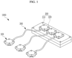
- An exemplary embodiment of the present invention provides a pneumatic-based tactile sensor including: a tactile sense transmitting pneumatic unit for generating pneumatic pressure by an external load applied to a first side; and a tactile sense receiving sensor unit for measuring the load by transforming a magnitude of pneumatic pressure of the tactile sense transmitting pneumatic unit into a displacement.
- the tactile sense receiving sensor unit is separately disposed from the tactile sense transmitting pneumatic unit, and may further include a tactile sense transmitting pneumatic line for connecting the tactile sense transmitting pneumatic unit and a displacement unit so as to transmit the pneumatic pressure of the tactile sense transmitting pneumatic unit to the tactile sense receiving sensor unit.
- Sensitivity and a measuring range of a tactile sensor may be controlled according to a flux intensity of the permanent magnet or a position of the permanent magnet.
- FIG. 2 show that a pneumatic outlet hole is not formed in an upper side of the housing 110 or a pneumatic outlet hole is formed in a lateral side of the housing 110, and for ease of understanding, FIG. 3 shows that a pneumatic outlet hole 115 is formed in the upper side of the housing 110.
- modified forms of the position of the pneumatic outlet hole are included in an exemplary embodiment of the present invention.
- the above-described housing 110 may be manufactured by using 3D printing, and its shapes may be transformed and manufactured in various ways according to customized shapes. However, the above-described housing 110 is required to have rigidity so that the same may not be changed by a pressure.
- the sensing membrane 120 is configured to close and seal a first opening of the housing 110, for example, as shown in FIG. 3 , an opening of a lower portion of the housing 110, and it is made of an elastic material.
- it may be made of a polydimethylsiloxane (PDMS) material, and without being limited to this, it may be one of flexible elastic polymers.
- PDMS polydimethylsiloxane
- a tactile sense receiving block 150 for directly sensing a tactile sense load is provided on an outer side of the sensing membrane 120, and a cross-section of the tactile sense receiving block 150 is formed to be smaller than a cross-section of the sensing membrane 120.
- a cross-section W1 of an opening (a first opening) of the housing 110 may be formed to be larger than a cross-section W2 of the pneumatic outlet hole 115 so that the pneumatic pressure generated through the pneumatic outlet hole 115 may be amplified.
- the pneumatic outlet hole 115 may be connected to a first end of the pneumatic line 300.
- FIG. 4 shows a projective and perspective view of a sensor unit 200 according to an exemplary embodiment of the present invention
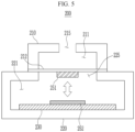
- FIG. 5 shows a cross-sectional view of the sensor unit 200.
- FIG. 5 shows a simplified configuration.
- the sensor unit 200 may include a flux-based displacement unit 210 and a magnetic resistance sensor unit 220.
- the flux-based displacement unit 210 includes a transmitting membrane 212, and a permanent magnet 251 may be provided.
- the flux-based displacement unit 210 is a parallelepiped in which a second space 211 is formed, and a pneumatic inlet hole 215 may be formed on a first side, while a second opening may be formed on a second side.
- a bottom side of the flux-based displacement unit 210 may be opened, and a pneumatic inlet hole 215 may be formed on an upper side.
- the first opening and the pneumatic outlet hole 115 may be disposed at various positions of the housing 110.
- FIG. 1 and FIG. 4 show that a pneumatic inlet hole may not be formed in the upper side of the flux-based displacement unit 210 or the pneumatic inlet hole is formed in the lateral side of the flux-based displacement unit 210, and for ease of understanding, FIG. 5 shows that a pneumatic inlet hole 215 is formed in the upper side of the flux-based displacement unit 210.
- modified forms of the position of the pneumatic inlet hole are included in an exemplary embodiment of the present invention.
- the above-described flux-based displacement unit 210 may be manufactured by using 3D printing, and its shapes may be transformed and manufactured in various ways according to customized shapes.
- a lower opening of the flux-based displacement unit 210 may be closed and sealed by the transmitting membrane 212, and the permanent magnet 251 may be inserted into the transmitting membrane 212 or may be combined to a lower side of the transmitting membrane 212.
- the transmitting membrane 212 may be made of a material with a low elastic coefficient so as to transmit a signal that is sensitive to the pneumatic pressure. For example, it may be made of an Ecoflex material with a low elastic coefficient (Young's modulus), and without being limited to this, one of flexible elastic polymers may be used.
- a second end of the pneumatic line 300 having a first end connected to the pneumatic outlet hole 115 is connected to the pneumatic inlet hole 215 to receive pneumatic pressure generated by the pneumatic unit 100.
- the magnetic resistance sensor unit 220 includes a substrate 230 and a magnetic resistance sensor 252.
- a third space 221 is formed inside the magnetic resistance sensor unit 220, and a flux-based displacement unit 210 may be combined to a first side of the magnetic resistance sensor unit 220, for example, as shown in FIG. 5 , an upper side of the magnetic resistance sensor unit 220.
- a third opening that is, a flux sensing opening 225, may be formed on the upper side of the magnetic resistance sensor unit 220 so that the transmitting membrane 212 and the permanent magnet 251 may be linked to the third space 221.
- the flux sensing opening 225 may be closed and sealed by the lower side of the flux-based displacement unit 210, and the transmitting membrane 212 may be combined to the permanent magnet 251 so that they may be exposed in the third space 221 through the flux sensing opening 225.
- the magnetic resistance sensor unit 220 may be manufactured by using 3D printing, and its shapes may be transformed and manufactured in various ways according to customized shapes.
- a substrate 230 and a magnetic resistance sensor 252 combined to an upper side of the substrate 230 are provided inside the magnetic resistance sensor unit 220, and are configured so that the magnetic resistance sensor may sense the flux of the permanent magnet 251. Therefore, intensity of an external stimulus is calculated according to magnetic resistance measured in the magnetic resistance sensor 252.
- This configuration may have the merit of less hysteresis since it uses pneumatic pressure when a pneumatic pressure is generated according to a stress transmitted from the outside, and it is transmitted to the sensor unit 200 to measure a fine stress applied to the tactile sense sensor with a flux size caused by the change of position of an internal magnet as varied resistance of the magnetic resistance sensor 252.
- the pneumatic unit 100 and the sensor unit 200 are separately configured and joined by the pneumatic line 300, so the pneumatic unit 100 may be separately disposed from the sensor unit 200. Accordingly, as a merit, the sensor unit 200 is not influenced when the change of an external electromagnetic field or a temperature is large on a portion for transmitting a tactile sense, or when a tactile sense is transmitted in the water.
- the tactile sense sensor 1000 may control sensitivity and a measurement range of the tactile sensor according to a thickness or a material of the sensing membrane 120 of the pneumatic unit 100 or the transmitting membrane 212 of the sensor unit 200.
- sensitivity of the tactile sensor and the measurement range may be controlled depending on flux intensity or position of the permanent magnet 251 combined to the transmitting membrane 212 as a merit.
- FIG. 6 shows a graph of a detection signal (voltage) according to a tactile sense load (pressure) with respect to time when a tactile sense is detected by using a tactile sense sensor 1000 according to an exemplary embodiment of the present invention
- FIG. 7 shows a graph of a detection signal (voltage) according to a tactile sense load (pressure) when a tactile sense sensor is used according to an exemplary embodiment of the present invention.
- FIG. 8 shows a graph of a detection signal (voltage) according to a tactile sense load (pressure) when a pneumatic unit 100 is provided in the air or water while sensing a tactile sense by use of a tactile sensor 1000 according to an exemplary embodiment of the present invention.
Landscapes
- Physics & Mathematics (AREA)
- General Physics & Mathematics (AREA)
- Chemical & Material Sciences (AREA)
- Analytical Chemistry (AREA)
- Electromagnetism (AREA)
- Force Measurement Appropriate To Specific Purposes (AREA)
Claims (6)
- Taktiler Sensor auf pneumatischer Basis, der Folgendes umfasst:eine den Tastsinn übertragende Pneumatikeinheit (100) zum Erzeugen von pneumatischem Druck durch eine externe Belastung, die auf eine erste Seite ausgeübt wird;eine den Tastsinn empfangende Sensoreinheit (200) zum Messen der Belastung durch Umwandeln einer Größe des pneumatischen Drucks der den Tastsinn übertragende Pneumatikeinheit in eine Verschiebung, wobei die den Tastsinn empfangende Sensoreinheit (200) separat von der den Tastsinn übertragenden Pneumatikeinheit (100) angeordnet ist; undeine den Tastsinn übertragende Pneumatikleitung (300) zum Verbinden der den Tastsinn übertragende Pneumatikeinheit (100) mit der den Tastsinn empfangenden Sensoreinheit (200), um den pneumatischen Druck der den Tastsinn übertragenden Pneumatikeinheit (100) an die den Tastsinn empfangende Sensoreinheit (200) zu übertragen,wobeidie den Tastsinn übertragende Pneumatikeinheit (100) Folgendes enthält:ein Gehäuse (110), das einen Innenbereich, in dem ein erster Raum (111) ausgebildet ist, eine erste Seite, in der eine erste Öffnung ausgebildet ist, und eine zweite Seite enthält, in der ein pneumatischer Auslass (115) ausgebildet ist; undeine Sensormembran (120), die aus einem elastischen Material hergestellt ist, zum Verschließen und Abdichten der ersten Öffnung,wobei ein Querschnitt der ersten Öffnung größer als ein Querschnitt des pneumatischen Auslasses (115) ist; undeinen den Tastsinn empfangenden Block (150) zum direkten Erfassen eine Tastsinnbelastung, die an einer Außenseite der Sensormembran (120) vorgesehen ist,wobei ein Querschnitt des den Tastsinn empfangenden Blocks (150) kleiner ist als ein Querschnitt des pneumatischen Auslasses (120).
- Taktiler Sensor auf pneumatischer Basis nach Anspruch 1, wobei
die den Tastsinn empfangende Sensoreinheit (200) einen von einem magnetischen Widerstandssensor, einem Kapazitätssensor, einem piezoresistiven Sensor und einem Kontaktwiderstandssensor enthält. - Taktiler Sensor auf pneumatischer Basis nach Anspruch 1, wobei
die den Tastsinn empfangende Sensoreinheit (200) Folgendes enthält:eine auf einem Magnetfluss basierende Verschiebungseinheit (210) zum Umwandeln einer Größe eines pneumatischen Drucks der den Tastsinn übertragenden Pneumatikeinheit (100) in eine magnetische Flussintensität; undeine magnetischen Widerstandssensoreinheit (220) zum Messen einer Größe der Belastung, indem die Flussintensität durch Verwendung eines magnetischen Widerstandssensors erfasst wird. - Taktiler Sensor auf pneumatischer Basis nach Anspruch 3, wobeidie auf einem Fluss basierende Verschiebungseinheit (210) einen Innenbereich, in dem ein zweiter Raum ausgebildet ist, eine erste Seite, auf der ein mit dem pneumatischen Auslass (115) verbundener pneumatischer Einlass (215) ausgebildet ist, und eine zweite Seite enthält, in der eine zweite Öffnung ausgebildet ist, undeine Übertragungsmembran (212) zum Verschließen und Abdichten der zweiten Öffnung enthält, undwobei der Permanentmagnet (251) mit der Übertragungsmembran kombiniert ist.
- Taktiler Sensor auf pneumatischer Basis nach Anspruch 4, wobeidie magnetische Widerstandssensoreinheit (220) einen Innenbereich, in dem ein dritter Raum ausgebildet ist, und eine erste Seite enthält, in der eine dritte Öffnung ausgebildet ist, die durch die auf einem Fluss basierende Verschiebungseinheit geschlossen und abgedichtet wird,die Übertragungsmembran (212) und der Permanentmagnet durch die dritte Öffnung freigelegt werden, unddie magnetischen Widerstandssensoreinheit (220) einen magnetischen Widerstandssensor enthält, der zum Erfassen eines Flusses des Permanentmagneten eingebaut ist.
- Taktiler Sensor auf pneumatischer Basis nach Anspruch 4, wobei
die Empfindlichkeit und ein Messbereich eines taktilen Sensors gemäß einer Flussintensität des Permanentmagneten (251) oder einer Position des Permanentmagneten (251) gesteuert werden.
Applications Claiming Priority (2)
| Application Number | Priority Date | Filing Date | Title |
|---|---|---|---|
| KR1020170030232A KR101980224B1 (ko) | 2017-03-09 | 2017-03-09 | 공압 기반 촉각센서 |
| PCT/KR2017/007002 WO2018164320A1 (ko) | 2017-03-09 | 2017-06-30 | 공압 기반 촉각센서 |
Publications (3)
| Publication Number | Publication Date |
|---|---|
| EP3594650A1 EP3594650A1 (de) | 2020-01-15 |
| EP3594650A4 EP3594650A4 (de) | 2021-01-13 |
| EP3594650B1 true EP3594650B1 (de) | 2024-06-19 |
Family
ID=63447842
Family Applications (1)
| Application Number | Title | Priority Date | Filing Date |
|---|---|---|---|
| EP17899762.3A Active EP3594650B1 (de) | 2017-03-09 | 2017-06-30 | Pneumatisch-basierter taktiler sensor |
Country Status (5)
| Country | Link |
|---|---|
| US (1) | US10908033B2 (de) |
| EP (1) | EP3594650B1 (de) |
| JP (1) | JP6748788B2 (de) |
| KR (1) | KR101980224B1 (de) |
| WO (1) | WO2018164320A1 (de) |
Families Citing this family (8)
| Publication number | Priority date | Publication date | Assignee | Title |
|---|---|---|---|---|
| KR102171596B1 (ko) * | 2019-02-21 | 2020-10-29 | 한국기계연구원 | 촉각 센서 |
| KR102267515B1 (ko) | 2020-01-09 | 2021-06-21 | 한국기계연구원 | 촉각 감지 시스템 |
| JP7461633B2 (ja) * | 2020-03-19 | 2024-04-04 | 国立大学法人大阪大学 | 触覚センサ |
| US11408788B2 (en) * | 2020-03-31 | 2022-08-09 | Toyota Research Institute, Inc. | Variable geometry and stiffness control for fluid filled sensor |
| CN111473805B (zh) * | 2020-04-17 | 2021-09-21 | 江苏多维科技有限公司 | 一种微机电环境传感器及其制备方法 |
| US12017343B2 (en) | 2020-08-04 | 2024-06-25 | Korea Advanced Institute Of Science And Technology | Tactile sensor, and tactile stimulation sensing method using the same, and robot skin and robot comprising the same |
| KR102887933B1 (ko) * | 2021-12-24 | 2025-11-19 | 한국과학기술연구원 | 인공 촉각 뉴런을 제공하는 회로 및 이를 기반으로 한 질병 예측 장치 |
| WO2024028285A1 (en) * | 2022-08-04 | 2024-02-08 | Analog Devices International Unlimited Company | Force detection based on position and/or movement of magnetically sensitive material |
Family Cites Families (17)
| Publication number | Priority date | Publication date | Assignee | Title |
|---|---|---|---|---|
| US3638497A (en) * | 1969-07-16 | 1972-02-01 | Transducer Systems Inc | Pressure and force transducer means |
| JPS60131306A (ja) * | 1983-12-21 | 1985-07-13 | Hitachi Ltd | タイヤ空気圧監視装置 |
| US4627292A (en) * | 1984-07-03 | 1986-12-09 | Randek Inc. | AC transducers, methods and systems |
| JPH066277B2 (ja) * | 1984-09-25 | 1994-01-26 | 日本電気株式会社 | 触覚センサ |
| WO1988007181A1 (en) * | 1987-03-09 | 1988-09-22 | Antonio Nicholas F D | Pressure sensor and transducer apparatus |
| JPH1043142A (ja) * | 1996-08-01 | 1998-02-17 | Olympus Optical Co Ltd | 触覚センサプローブ |
| JPH10170377A (ja) * | 1996-12-11 | 1998-06-26 | Toyota Motor Corp | 圧力検出装置 |
| JP4189709B2 (ja) | 1999-05-13 | 2008-12-03 | ソニー株式会社 | モーションキャプチャー装置 |
| JPWO2007083546A1 (ja) | 2006-01-19 | 2009-06-11 | 国立大学法人豊橋技術科学大学 | 触覚センサ装置 |
| KR101087795B1 (ko) | 2006-07-21 | 2011-11-30 | 주식회사 하이닉스반도체 | 반도체 소자의 콘택 패턴 형성 방법 |
| US20160188086A1 (en) * | 2008-01-04 | 2016-06-30 | Tactus Technology, Inc. | Dynamic tactile interface |
| US8087299B1 (en) * | 2010-06-22 | 2012-01-03 | Guay Guay Trading Co., Ltd. | Target pressure detection device |
| WO2012054781A1 (en) * | 2010-10-20 | 2012-04-26 | Tactus Technology | User interface system and method |
| JP6048947B2 (ja) | 2012-02-20 | 2016-12-21 | 国立大学法人 香川大学 | 触覚センサ |
| JP5999591B2 (ja) | 2012-03-30 | 2016-09-28 | 独立行政法人国立高等専門学校機構 | 触覚センサ |
| KR101301006B1 (ko) * | 2012-07-03 | 2013-08-29 | 한국과학기술연구원 | 촉각 제시 장치 |
| JP6006277B2 (ja) * | 2014-11-06 | 2016-10-12 | ファナック株式会社 | 産業用ロボットのプログラム修正装置及びプログラム修正方法 |
-
2017
- 2017-03-09 KR KR1020170030232A patent/KR101980224B1/ko active Active
- 2017-06-30 US US16/492,429 patent/US10908033B2/en active Active
- 2017-06-30 JP JP2019548554A patent/JP6748788B2/ja active Active
- 2017-06-30 WO PCT/KR2017/007002 patent/WO2018164320A1/ko not_active Ceased
- 2017-06-30 EP EP17899762.3A patent/EP3594650B1/de active Active
Also Published As
| Publication number | Publication date |
|---|---|
| KR20180103375A (ko) | 2018-09-19 |
| JP2020510201A (ja) | 2020-04-02 |
| EP3594650A1 (de) | 2020-01-15 |
| US10908033B2 (en) | 2021-02-02 |
| JP6748788B2 (ja) | 2020-09-02 |
| WO2018164320A1 (ko) | 2018-09-13 |
| KR101980224B1 (ko) | 2019-05-21 |
| EP3594650A4 (de) | 2021-01-13 |
| US20200041361A1 (en) | 2020-02-06 |
Similar Documents
| Publication | Publication Date | Title |
|---|---|---|
| US10908033B2 (en) | Pneumatic-based tactile sensor | |
| KR101449410B1 (ko) | 전도성 나노 또는 마이크로 기둥의 맞물림을 이용한 촉각 센서 | |
| CN101578507B (zh) | 双量程绝对压力感测裸片 | |
| CN102589791B (zh) | 具有低成本封装的压力传感器 | |
| CN205843877U (zh) | 介质隔离式压力传感器 | |
| JP5778619B2 (ja) | 圧力センサ | |
| CN101329187B (zh) | 用于测量多个被测对象的组合传感器系统 | |
| KR101486217B1 (ko) | 커브 형 전도성 나노 또는 마이크로 필러를 이용한 촉각 센서 | |
| US8082798B2 (en) | Sensor geometry for improved package stress isolation | |
| CN110036269B (zh) | 压力传感器 | |
| KR101449407B1 (ko) | 압전소자의 맞물림을 이용한 촉각 센서 | |
| JP6144540B2 (ja) | 圧力センサ | |
| JP2020180972A (ja) | 複数範囲構造を有するセンサ組立体 | |
| US10267699B2 (en) | Pressure sensor element and method of manufacturing the same | |
| US8511168B2 (en) | Sensor element for capacitively measuring differential pressure | |
| US20090205432A1 (en) | Pressure sensing system and method | |
| KR102171596B1 (ko) | 촉각 센서 | |
| CN101379377A (zh) | 可偏转微机械系统及其应用 | |
| KR102267515B1 (ko) | 촉각 감지 시스템 | |
| JP2014134543A (ja) | センサ素子、感圧型センサ及び触覚センサ | |
| JP6521441B2 (ja) | 圧力センサ | |
| JP6230334B2 (ja) | 温度センサ | |
| CN119023124A (zh) | 基于soi的压力传感器 | |
| WO2015170957A1 (en) | A self-calibrated miniaturized pressure sensor |
Legal Events
| Date | Code | Title | Description |
|---|---|---|---|
| STAA | Information on the status of an ep patent application or granted ep patent |
Free format text: STATUS: THE INTERNATIONAL PUBLICATION HAS BEEN MADE |
|
| PUAI | Public reference made under article 153(3) epc to a published international application that has entered the european phase |
Free format text: ORIGINAL CODE: 0009012 |
|
| STAA | Information on the status of an ep patent application or granted ep patent |
Free format text: STATUS: REQUEST FOR EXAMINATION WAS MADE |
|
| 17P | Request for examination filed |
Effective date: 20190911 |
|
| AK | Designated contracting states |
Kind code of ref document: A1 Designated state(s): AL AT BE BG CH CY CZ DE DK EE ES FI FR GB GR HR HU IE IS IT LI LT LU LV MC MK MT NL NO PL PT RO RS SE SI SK SM TR |
|
| AX | Request for extension of the european patent |
Extension state: BA ME |
|
| DAV | Request for validation of the european patent (deleted) | ||
| DAX | Request for extension of the european patent (deleted) | ||
| A4 | Supplementary search report drawn up and despatched |
Effective date: 20201211 |
|
| RIC1 | Information provided on ipc code assigned before grant |
Ipc: G01L 1/20 20060101ALI20201207BHEP Ipc: G01L 9/14 20060101ALI20201207BHEP Ipc: G01L 1/16 20060101ALI20201207BHEP Ipc: G01L 1/02 20060101ALI20201207BHEP Ipc: G01L 9/00 20060101ALI20201207BHEP Ipc: G01L 1/14 20060101ALI20201207BHEP Ipc: G01L 5/22 20060101AFI20201207BHEP Ipc: G01L 1/12 20060101ALI20201207BHEP |
|
| RIC1 | Information provided on ipc code assigned before grant |
Ipc: G01L 9/00 20060101ALI20231130BHEP Ipc: G01L 9/14 20060101ALI20231130BHEP Ipc: G01L 1/12 20060101ALI20231130BHEP Ipc: G01L 1/20 20060101ALI20231130BHEP Ipc: G01L 1/16 20060101ALI20231130BHEP Ipc: G01L 1/14 20060101ALI20231130BHEP Ipc: G01L 1/02 20060101ALI20231130BHEP Ipc: G01L 5/22 20060101AFI20231130BHEP |
|
| GRAP | Despatch of communication of intention to grant a patent |
Free format text: ORIGINAL CODE: EPIDOSNIGR1 |
|
| STAA | Information on the status of an ep patent application or granted ep patent |
Free format text: STATUS: GRANT OF PATENT IS INTENDED |
|
| INTG | Intention to grant announced |
Effective date: 20240117 |
|
| GRAS | Grant fee paid |
Free format text: ORIGINAL CODE: EPIDOSNIGR3 |
|
| GRAA | (expected) grant |
Free format text: ORIGINAL CODE: 0009210 |
|
| STAA | Information on the status of an ep patent application or granted ep patent |
Free format text: STATUS: THE PATENT HAS BEEN GRANTED |
|
| AK | Designated contracting states |
Kind code of ref document: B1 Designated state(s): AL AT BE BG CH CY CZ DE DK EE ES FI FR GB GR HR HU IE IS IT LI LT LU LV MC MK MT NL NO PL PT RO RS SE SI SK SM TR |
|
| REG | Reference to a national code |
Ref country code: GB Ref legal event code: FG4D |
|
| REG | Reference to a national code |
Ref country code: CH Ref legal event code: EP |
|
| REG | Reference to a national code |
Ref country code: DE Ref legal event code: R096 Ref document number: 602017082745 Country of ref document: DE |
|
| PG25 | Lapsed in a contracting state [announced via postgrant information from national office to epo] |
Ref country code: BG Free format text: LAPSE BECAUSE OF FAILURE TO SUBMIT A TRANSLATION OF THE DESCRIPTION OR TO PAY THE FEE WITHIN THE PRESCRIBED TIME-LIMIT Effective date: 20240619 |
|
| PG25 | Lapsed in a contracting state [announced via postgrant information from national office to epo] |
Ref country code: HR Free format text: LAPSE BECAUSE OF FAILURE TO SUBMIT A TRANSLATION OF THE DESCRIPTION OR TO PAY THE FEE WITHIN THE PRESCRIBED TIME-LIMIT Effective date: 20240619 Ref country code: FI Free format text: LAPSE BECAUSE OF FAILURE TO SUBMIT A TRANSLATION OF THE DESCRIPTION OR TO PAY THE FEE WITHIN THE PRESCRIBED TIME-LIMIT Effective date: 20240619 |
|
| REG | Reference to a national code |
Ref country code: LT Ref legal event code: MG9D |
|
| PG25 | Lapsed in a contracting state [announced via postgrant information from national office to epo] |
Ref country code: GR Free format text: LAPSE BECAUSE OF FAILURE TO SUBMIT A TRANSLATION OF THE DESCRIPTION OR TO PAY THE FEE WITHIN THE PRESCRIBED TIME-LIMIT Effective date: 20240920 |
|
| PG25 | Lapsed in a contracting state [announced via postgrant information from national office to epo] |
Ref country code: LV Free format text: LAPSE BECAUSE OF FAILURE TO SUBMIT A TRANSLATION OF THE DESCRIPTION OR TO PAY THE FEE WITHIN THE PRESCRIBED TIME-LIMIT Effective date: 20240619 |
|
| PG25 | Lapsed in a contracting state [announced via postgrant information from national office to epo] |
Ref country code: NO Free format text: LAPSE BECAUSE OF FAILURE TO SUBMIT A TRANSLATION OF THE DESCRIPTION OR TO PAY THE FEE WITHIN THE PRESCRIBED TIME-LIMIT Effective date: 20240919 Ref country code: LV Free format text: LAPSE BECAUSE OF FAILURE TO SUBMIT A TRANSLATION OF THE DESCRIPTION OR TO PAY THE FEE WITHIN THE PRESCRIBED TIME-LIMIT Effective date: 20240619 Ref country code: HR Free format text: LAPSE BECAUSE OF FAILURE TO SUBMIT A TRANSLATION OF THE DESCRIPTION OR TO PAY THE FEE WITHIN THE PRESCRIBED TIME-LIMIT Effective date: 20240619 Ref country code: GR Free format text: LAPSE BECAUSE OF FAILURE TO SUBMIT A TRANSLATION OF THE DESCRIPTION OR TO PAY THE FEE WITHIN THE PRESCRIBED TIME-LIMIT Effective date: 20240920 Ref country code: FI Free format text: LAPSE BECAUSE OF FAILURE TO SUBMIT A TRANSLATION OF THE DESCRIPTION OR TO PAY THE FEE WITHIN THE PRESCRIBED TIME-LIMIT Effective date: 20240619 Ref country code: BG Free format text: LAPSE BECAUSE OF FAILURE TO SUBMIT A TRANSLATION OF THE DESCRIPTION OR TO PAY THE FEE WITHIN THE PRESCRIBED TIME-LIMIT Effective date: 20240619 Ref country code: RS Free format text: LAPSE BECAUSE OF FAILURE TO SUBMIT A TRANSLATION OF THE DESCRIPTION OR TO PAY THE FEE WITHIN THE PRESCRIBED TIME-LIMIT Effective date: 20240919 |
|
| PG25 | Lapsed in a contracting state [announced via postgrant information from national office to epo] |
Ref country code: NL Free format text: LAPSE BECAUSE OF FAILURE TO SUBMIT A TRANSLATION OF THE DESCRIPTION OR TO PAY THE FEE WITHIN THE PRESCRIBED TIME-LIMIT Effective date: 20240619 |
|
| REG | Reference to a national code |
Ref country code: AT Ref legal event code: MK05 Ref document number: 1696195 Country of ref document: AT Kind code of ref document: T Effective date: 20240619 |
|
| PG25 | Lapsed in a contracting state [announced via postgrant information from national office to epo] |
Ref country code: NL Free format text: LAPSE BECAUSE OF FAILURE TO SUBMIT A TRANSLATION OF THE DESCRIPTION OR TO PAY THE FEE WITHIN THE PRESCRIBED TIME-LIMIT Effective date: 20240619 |
|
| PG25 | Lapsed in a contracting state [announced via postgrant information from national office to epo] |
Ref country code: PT Free format text: LAPSE BECAUSE OF FAILURE TO SUBMIT A TRANSLATION OF THE DESCRIPTION OR TO PAY THE FEE WITHIN THE PRESCRIBED TIME-LIMIT Effective date: 20241021 |
|
| PG25 | Lapsed in a contracting state [announced via postgrant information from national office to epo] |
Ref country code: PT Free format text: LAPSE BECAUSE OF FAILURE TO SUBMIT A TRANSLATION OF THE DESCRIPTION OR TO PAY THE FEE WITHIN THE PRESCRIBED TIME-LIMIT Effective date: 20241021 |
|
| PG25 | Lapsed in a contracting state [announced via postgrant information from national office to epo] |
Ref country code: PL Free format text: LAPSE BECAUSE OF FAILURE TO SUBMIT A TRANSLATION OF THE DESCRIPTION OR TO PAY THE FEE WITHIN THE PRESCRIBED TIME-LIMIT Effective date: 20240619 |
|
| PG25 | Lapsed in a contracting state [announced via postgrant information from national office to epo] |
Ref country code: EE Free format text: LAPSE BECAUSE OF FAILURE TO SUBMIT A TRANSLATION OF THE DESCRIPTION OR TO PAY THE FEE WITHIN THE PRESCRIBED TIME-LIMIT Effective date: 20240619 |
|
| PG25 | Lapsed in a contracting state [announced via postgrant information from national office to epo] |
Ref country code: IS Free format text: LAPSE BECAUSE OF FAILURE TO SUBMIT A TRANSLATION OF THE DESCRIPTION OR TO PAY THE FEE WITHIN THE PRESCRIBED TIME-LIMIT Effective date: 20241019 Ref country code: AT Free format text: LAPSE BECAUSE OF FAILURE TO SUBMIT A TRANSLATION OF THE DESCRIPTION OR TO PAY THE FEE WITHIN THE PRESCRIBED TIME-LIMIT Effective date: 20240619 |
|
| PG25 | Lapsed in a contracting state [announced via postgrant information from national office to epo] |
Ref country code: CZ Free format text: LAPSE BECAUSE OF FAILURE TO SUBMIT A TRANSLATION OF THE DESCRIPTION OR TO PAY THE FEE WITHIN THE PRESCRIBED TIME-LIMIT Effective date: 20240619 |
|
| PG25 | Lapsed in a contracting state [announced via postgrant information from national office to epo] |
Ref country code: SK Free format text: LAPSE BECAUSE OF FAILURE TO SUBMIT A TRANSLATION OF THE DESCRIPTION OR TO PAY THE FEE WITHIN THE PRESCRIBED TIME-LIMIT Effective date: 20240619 Ref country code: RO Free format text: LAPSE BECAUSE OF FAILURE TO SUBMIT A TRANSLATION OF THE DESCRIPTION OR TO PAY THE FEE WITHIN THE PRESCRIBED TIME-LIMIT Effective date: 20240619 |
|
| PG25 | Lapsed in a contracting state [announced via postgrant information from national office to epo] |
Ref country code: SM Free format text: LAPSE BECAUSE OF FAILURE TO SUBMIT A TRANSLATION OF THE DESCRIPTION OR TO PAY THE FEE WITHIN THE PRESCRIBED TIME-LIMIT Effective date: 20240619 Ref country code: ES Free format text: LAPSE BECAUSE OF FAILURE TO SUBMIT A TRANSLATION OF THE DESCRIPTION OR TO PAY THE FEE WITHIN THE PRESCRIBED TIME-LIMIT Effective date: 20240619 |
|
| PG25 | Lapsed in a contracting state [announced via postgrant information from national office to epo] |
Ref country code: SM Free format text: LAPSE BECAUSE OF FAILURE TO SUBMIT A TRANSLATION OF THE DESCRIPTION OR TO PAY THE FEE WITHIN THE PRESCRIBED TIME-LIMIT Effective date: 20240619 Ref country code: SK Free format text: LAPSE BECAUSE OF FAILURE TO SUBMIT A TRANSLATION OF THE DESCRIPTION OR TO PAY THE FEE WITHIN THE PRESCRIBED TIME-LIMIT Effective date: 20240619 Ref country code: RO Free format text: LAPSE BECAUSE OF FAILURE TO SUBMIT A TRANSLATION OF THE DESCRIPTION OR TO PAY THE FEE WITHIN THE PRESCRIBED TIME-LIMIT Effective date: 20240619 Ref country code: PL Free format text: LAPSE BECAUSE OF FAILURE TO SUBMIT A TRANSLATION OF THE DESCRIPTION OR TO PAY THE FEE WITHIN THE PRESCRIBED TIME-LIMIT Effective date: 20240619 Ref country code: IS Free format text: LAPSE BECAUSE OF FAILURE TO SUBMIT A TRANSLATION OF THE DESCRIPTION OR TO PAY THE FEE WITHIN THE PRESCRIBED TIME-LIMIT Effective date: 20241019 Ref country code: ES Free format text: LAPSE BECAUSE OF FAILURE TO SUBMIT A TRANSLATION OF THE DESCRIPTION OR TO PAY THE FEE WITHIN THE PRESCRIBED TIME-LIMIT Effective date: 20240619 Ref country code: EE Free format text: LAPSE BECAUSE OF FAILURE TO SUBMIT A TRANSLATION OF THE DESCRIPTION OR TO PAY THE FEE WITHIN THE PRESCRIBED TIME-LIMIT Effective date: 20240619 Ref country code: CZ Free format text: LAPSE BECAUSE OF FAILURE TO SUBMIT A TRANSLATION OF THE DESCRIPTION OR TO PAY THE FEE WITHIN THE PRESCRIBED TIME-LIMIT Effective date: 20240619 Ref country code: AT Free format text: LAPSE BECAUSE OF FAILURE TO SUBMIT A TRANSLATION OF THE DESCRIPTION OR TO PAY THE FEE WITHIN THE PRESCRIBED TIME-LIMIT Effective date: 20240619 |
|
| PG25 | Lapsed in a contracting state [announced via postgrant information from national office to epo] |
Ref country code: IT Free format text: LAPSE BECAUSE OF FAILURE TO SUBMIT A TRANSLATION OF THE DESCRIPTION OR TO PAY THE FEE WITHIN THE PRESCRIBED TIME-LIMIT Effective date: 20240619 |
|
| PG25 | Lapsed in a contracting state [announced via postgrant information from national office to epo] |
Ref country code: LU Free format text: LAPSE BECAUSE OF NON-PAYMENT OF DUE FEES Effective date: 20240630 |
|
| PG25 | Lapsed in a contracting state [announced via postgrant information from national office to epo] |
Ref country code: MC Free format text: LAPSE BECAUSE OF FAILURE TO SUBMIT A TRANSLATION OF THE DESCRIPTION OR TO PAY THE FEE WITHIN THE PRESCRIBED TIME-LIMIT Effective date: 20240619 |
|
| REG | Reference to a national code |
Ref country code: DE Ref legal event code: R097 Ref document number: 602017082745 Country of ref document: DE |
|
| PG25 | Lapsed in a contracting state [announced via postgrant information from national office to epo] |
Ref country code: MC Free format text: LAPSE BECAUSE OF FAILURE TO SUBMIT A TRANSLATION OF THE DESCRIPTION OR TO PAY THE FEE WITHIN THE PRESCRIBED TIME-LIMIT Effective date: 20240619 |
|
| PG25 | Lapsed in a contracting state [announced via postgrant information from national office to epo] |
Ref country code: DK Free format text: LAPSE BECAUSE OF FAILURE TO SUBMIT A TRANSLATION OF THE DESCRIPTION OR TO PAY THE FEE WITHIN THE PRESCRIBED TIME-LIMIT Effective date: 20240619 |
|
| PG25 | Lapsed in a contracting state [announced via postgrant information from national office to epo] |
Ref country code: IE Free format text: LAPSE BECAUSE OF NON-PAYMENT OF DUE FEES Effective date: 20240630 |
|
| PG25 | Lapsed in a contracting state [announced via postgrant information from national office to epo] |
Ref country code: BE Free format text: LAPSE BECAUSE OF NON-PAYMENT OF DUE FEES Effective date: 20240630 |
|
| PLBE | No opposition filed within time limit |
Free format text: ORIGINAL CODE: 0009261 |
|
| STAA | Information on the status of an ep patent application or granted ep patent |
Free format text: STATUS: NO OPPOSITION FILED WITHIN TIME LIMIT |
|
| REG | Reference to a national code |
Ref country code: BE Ref legal event code: MM Effective date: 20240630 |
|
| 26N | No opposition filed |
Effective date: 20250320 |
|
| GBPC | Gb: european patent ceased through non-payment of renewal fee |
Effective date: 20240919 |
|
| PGFP | Annual fee paid to national office [announced via postgrant information from national office to epo] |
Ref country code: DE Payment date: 20250507 Year of fee payment: 9 |
|
| PG25 | Lapsed in a contracting state [announced via postgrant information from national office to epo] |
Ref country code: GB Free format text: LAPSE BECAUSE OF NON-PAYMENT OF DUE FEES Effective date: 20240919 |
|
| PGFP | Annual fee paid to national office [announced via postgrant information from national office to epo] |
Ref country code: FR Payment date: 20250508 Year of fee payment: 9 |
|
| PG25 | Lapsed in a contracting state [announced via postgrant information from national office to epo] |
Ref country code: SE Free format text: LAPSE BECAUSE OF FAILURE TO SUBMIT A TRANSLATION OF THE DESCRIPTION OR TO PAY THE FEE WITHIN THE PRESCRIBED TIME-LIMIT Effective date: 20240619 |
|
| PGFP | Annual fee paid to national office [announced via postgrant information from national office to epo] |
Ref country code: CH Payment date: 20250701 Year of fee payment: 9 |
|
| PG25 | Lapsed in a contracting state [announced via postgrant information from national office to epo] |
Ref country code: CY Free format text: LAPSE BECAUSE OF FAILURE TO SUBMIT A TRANSLATION OF THE DESCRIPTION OR TO PAY THE FEE WITHIN THE PRESCRIBED TIME-LIMIT; INVALID AB INITIO Effective date: 20170630 |
|
| PG25 | Lapsed in a contracting state [announced via postgrant information from national office to epo] |
Ref country code: HU Free format text: LAPSE BECAUSE OF FAILURE TO SUBMIT A TRANSLATION OF THE DESCRIPTION OR TO PAY THE FEE WITHIN THE PRESCRIBED TIME-LIMIT; INVALID AB INITIO Effective date: 20170630 |