EP3594572A1 - Kraftstoffanschlusseinheit - Google Patents
Kraftstoffanschlusseinheit Download PDFInfo
- Publication number
- EP3594572A1 EP3594572A1 EP19183788.9A EP19183788A EP3594572A1 EP 3594572 A1 EP3594572 A1 EP 3594572A1 EP 19183788 A EP19183788 A EP 19183788A EP 3594572 A1 EP3594572 A1 EP 3594572A1
- Authority
- EP
- European Patent Office
- Prior art keywords
- fuel
- connection unit
- connection
- unit body
- pump
- Prior art date
- Legal status (The legal status is an assumption and is not a legal conclusion. Google has not performed a legal analysis and makes no representation as to the accuracy of the status listed.)
- Granted
Links
Images



Classifications
-
- F—MECHANICAL ENGINEERING; LIGHTING; HEATING; WEAPONS; BLASTING
- F23—COMBUSTION APPARATUS; COMBUSTION PROCESSES
- F23K—FEEDING FUEL TO COMBUSTION APPARATUS
- F23K5/00—Feeding or distributing other fuel to combustion apparatus
- F23K5/02—Liquid fuel
- F23K5/14—Details thereof
-
- B—PERFORMING OPERATIONS; TRANSPORTING
- B60—VEHICLES IN GENERAL
- B60H—ARRANGEMENTS OF HEATING, COOLING, VENTILATING OR OTHER AIR-TREATING DEVICES SPECIALLY ADAPTED FOR PASSENGER OR GOODS SPACES OF VEHICLES
- B60H1/00—Heating, cooling or ventilating devices
- B60H1/22—Heating, cooling or ventilating devices the heat source being other than the propulsion plant
- B60H1/2203—Heating, cooling or ventilating devices the heat source being other than the propulsion plant the heat being derived from burners
-
- B—PERFORMING OPERATIONS; TRANSPORTING
- B60—VEHICLES IN GENERAL
- B60H—ARRANGEMENTS OF HEATING, COOLING, VENTILATING OR OTHER AIR-TREATING DEVICES SPECIALLY ADAPTED FOR PASSENGER OR GOODS SPACES OF VEHICLES
- B60H1/00—Heating, cooling or ventilating devices
- B60H1/22—Heating, cooling or ventilating devices the heat source being other than the propulsion plant
-
- F—MECHANICAL ENGINEERING; LIGHTING; HEATING; WEAPONS; BLASTING
- F23—COMBUSTION APPARATUS; COMBUSTION PROCESSES
- F23K—FEEDING FUEL TO COMBUSTION APPARATUS
- F23K5/00—Feeding or distributing other fuel to combustion apparatus
- F23K5/02—Liquid fuel
-
- B—PERFORMING OPERATIONS; TRANSPORTING
- B60—VEHICLES IN GENERAL
- B60H—ARRANGEMENTS OF HEATING, COOLING, VENTILATING OR OTHER AIR-TREATING DEVICES SPECIALLY ADAPTED FOR PASSENGER OR GOODS SPACES OF VEHICLES
- B60H1/00—Heating, cooling or ventilating devices
- B60H1/22—Heating, cooling or ventilating devices the heat source being other than the propulsion plant
- B60H2001/2268—Constructional features
- B60H2001/2271—Heat exchangers, burners, ignition devices
-
- B—PERFORMING OPERATIONS; TRANSPORTING
- B60—VEHICLES IN GENERAL
- B60H—ARRANGEMENTS OF HEATING, COOLING, VENTILATING OR OTHER AIR-TREATING DEVICES SPECIALLY ADAPTED FOR PASSENGER OR GOODS SPACES OF VEHICLES
- B60H1/00—Heating, cooling or ventilating devices
- B60H1/22—Heating, cooling or ventilating devices the heat source being other than the propulsion plant
- B60H2001/2268—Constructional features
- B60H2001/2284—Fuel supply
-
- F—MECHANICAL ENGINEERING; LIGHTING; HEATING; WEAPONS; BLASTING
- F23—COMBUSTION APPARATUS; COMBUSTION PROCESSES
- F23D—BURNERS
- F23D2900/00—Special features of, or arrangements for burners using fluid fuels or solid fuels suspended in a carrier gas
- F23D2900/21—Burners specially adapted for a particular use
- F23D2900/21002—Burners specially adapted for a particular use for use in car heating systems
-
- F—MECHANICAL ENGINEERING; LIGHTING; HEATING; WEAPONS; BLASTING
- F23—COMBUSTION APPARATUS; COMBUSTION PROCESSES
- F23K—FEEDING FUEL TO COMBUSTION APPARATUS
- F23K2203/00—Feeding arrangements
- F23K2203/10—Supply line fittings
-
- F—MECHANICAL ENGINEERING; LIGHTING; HEATING; WEAPONS; BLASTING
- F23—COMBUSTION APPARATUS; COMBUSTION PROCESSES
- F23K—FEEDING FUEL TO COMBUSTION APPARATUS
- F23K2203/00—Feeding arrangements
- F23K2203/10—Supply line fittings
- F23K2203/104—Metering devices
-
- F—MECHANICAL ENGINEERING; LIGHTING; HEATING; WEAPONS; BLASTING
- F23—COMBUSTION APPARATUS; COMBUSTION PROCESSES
- F23K—FEEDING FUEL TO COMBUSTION APPARATUS
- F23K2400/00—Pretreatment and supply of gaseous fuel
- F23K2400/20—Supply line arrangements
-
- F—MECHANICAL ENGINEERING; LIGHTING; HEATING; WEAPONS; BLASTING
- F23—COMBUSTION APPARATUS; COMBUSTION PROCESSES
- F23K—FEEDING FUEL TO COMBUSTION APPARATUS
- F23K2900/00—Special features of, or arrangements for fuel supplies
- F23K2900/05142—Special materials for liquid fuel supply lines
-
- F—MECHANICAL ENGINEERING; LIGHTING; HEATING; WEAPONS; BLASTING
- F23—COMBUSTION APPARATUS; COMBUSTION PROCESSES
- F23N—REGULATING OR CONTROLLING COMBUSTION
- F23N2241/00—Applications
- F23N2241/14—Vehicle heating, the heat being derived otherwise than from the propulsion plant
Definitions
- the present invention relates to a fuel connection unit by means of which a fuel-operated vehicle heater can be connected to a fuel reservoir or the fuel flowing in from a fuel reservoir can be introduced into the heater.
- Such a fuel connection unit is from the subsequently published German patent application DE 10 2017 123 046 known.
- This known fuel connection unit comprises a disk-like connection unit body which is or can be arranged in an associated opening of a heater housing.
- a fuel delivery line connection area leads away from the connection unit body on a side facing the interior of the heater housing.
- a fuel delivery line leading to a burner area in the interior of the heater can be connected to this in order to direct fuel in the direction of a porous evaporator medium provided in the burner area.
- a fuel supply line connection region extends in a direction opposite to the extension of the fuel delivery line connection region away from the connection unit body.
- a fuel supply line leading from a reservoir can be connected to this.
- a fuel connection unit for a fuel-operated vehicle heating device comprising a connection unit body to be attached to a heater housing, a fuel delivery line connection area projecting from the connection unit body for connecting a fuel delivery line leading to a combustion chamber, and one Fuel supply line connection area protruding from the connection unit body for connecting a fuel supply line, at least one functional unit for influencing the fuel flow in a fuel flow volume formed in the connection unit body being provided in the connection unit body.
- Integrating a functional unit into the fuel connection unit makes it possible to influence the flow behavior of fuel through the fuel connection unit without having to provide a corresponding functional unit elsewhere. On the one hand, this leads to a saving of installation space and, on the other hand, makes it possible to implement the function to be provided by such a functional unit close to the vehicle heater.
- the at least one functional unit comprises a pulsation damper. It is thus ensured that such a pulsation damper can smooth or eliminate fluctuations in the fuel pressure very close to the point at which the fuel is released into a burner area.
- the pulsation damper can comprise a pressure compensation volume and a flexible separating element that separates the pressure compensation volume from the fuel flow volume in the connector unit body.
- the pulsation damper comprises a pulsation damper body that provides the pressure compensation volume, the flexible separating element on the pulsation damper body finally determining the pressure compensation volume, wherein a damper receptacle recess that accommodates the pulsation damper can also be formed in the connection unit body.
- the at least one functional unit can comprise a fuel valve.
- the supply or delivery of fuel or fuel vapor in the immediate vicinity of the burner area of such a vehicle heating device can thus be interrupted or released.
- the fuel valve comprise a check valve which blocks the fuel connection unit against flow in the direction from the fuel delivery line connection area to the fuel supply line connection area.
- the check valve comprises a prestressing element, preferably a prestressing spring, supported on a first connection unit body part, and a valve element, preferably a valve ball, pressed against a valve seat on a second connection unit body part by the prestressing element.
- a prestressing element preferably a prestressing spring
- the fuel valve comprises a switching valve which can be actuated to release and block a flow path from the fuel supply line connection area to the fuel delivery line connection area.
- the at least one functional unit can comprise a fuel pump.
- the fuel pump comprises, for example, an electromagnet unit which is fixedly supported on the connection unit body and a pump piston which can be moved linearly back and forth in a pump chamber and an armature provided on the pump piston for magnetic interaction with the electromagnet unit, the pump piston being driven by electrical excitation of the electromagnet unit in the direction of ejecting fuel the pump chamber is movable and can be moved in the direction of receiving fuel in the pump chamber by a prestressing element, preferably a prestressing spring.
- a fuel pump is designed as a metering pump, in which the pump piston acting as a pumping element is moved under the driving action of the electromagnetic drive unit to deliver fuel.
- such a fuel pump can comprise a piezo element as a drive unit, which changes its shape when electrically excited and thereby acts as a pumping element or moves a pumping element for conveying fuel.
- the at least one functional unit can comprise a fuel filter.
- the fuel supply line connection area and the fuel delivery line connection area be arranged in alignment with one another.
- connection unit body can be formed integrally with the fuel supply line connection area and the fuel delivery line connection area, that is to say as a block of material produced for example in a casting process.
- the invention further relates to a fuel-operated vehicle heater, comprising a fuel connection unit constructed according to the invention and inserted into a heater housing.
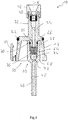
- a fuel connection unit for a fuel-operated vehicle heater is generally designated by 10.
- the fuel connection unit 10 comprises a disk-like connection unit body 12, which is inserted into an opening 14 of a heater housing 16 of a vehicle heater, generally designated 18, which is assigned to it.
- the connection unit body 12 can be surrounded by a sealing element 22, which can be clamped between the latter and the heater housing 16.
- a locking element 24 is provided on the connection unit body 12, which engages behind a locking projection 28 engaging in a locking recess 26 of the heater housing 16 and thus prevents the fuel connection unit 10 from being pulled out or falling out of the opening 14.
- a plurality of such latching elements 24 can be provided over the circumference of the connection unit body 12 provided in a disk-like shape.
- a fuel delivery line connection region 32 extends from the latter.
- This fuel delivery connection line region 32 which is designed in the manner of a pipe socket, has in its interior a fuel channel 34 which, on the one hand, is open to a fuel flow volume 36 formed in the connection unit body 12 and, on the other hand, accommodates, for example, two sealing elements 40 in an enlarged end region 38.
- a funnel-shaped holding element 42 which holds the sealing elements 40 in the fuel channel 34, is carried, through which a fuel delivery line extending in the interior 20 of the heater housing 16 can be inserted.
- the fuel delivery line which is constructed, for example, as a rigid pipeline made of metal material, is also connected to the fuel delivery line region 32 in a manner secured against the escape of fuel by the clamping action of the sealing elements 40.
- a fuel supply line connection area 46 extends from the connection unit body 12 offset to the fuel delivery connection line area 32 on the side 44 to be oriented in an outward direction. This, too, is designed in the manner of a pipe socket and provides in its interior a fuel channel 48 which is open to the fuel flow volume 36 in the connection unit body 12.
- a fuel line for example in the form of a flexible hose, can be pushed onto the fuel supply line connection area 46 in order to direct fuel flowing in from a fuel reservoir into the fuel flow volume 36 and via this the fuel channel 34.
- connection unit body 12 is integral with the fuel delivery line connection area 32, the fuel supply line connection area 46 and the latching element (s) 24, that is to say as a material block, for example in a casting process and for example made of plastic material.
- a functional unit, generally designated 50, is provided on the connection unit body 12 of the fuel connection unit 10.
- the functional unit 50 is designed in the illustrated embodiment as a pulsation damper 52 and comprises a pot-like pulsation damper body 54 accommodated in a damper receiving recess 51, in which a body with gas, such as e.g. B. air, filled pressure equalization volume 56 is provided.
- the pressure equalization volume 56 is closed in the direction of the fuel flow volume 36 by a flexible, for example membrane-like, separating member 58 which is firmly supported on the pulsation damper body 54.
- the pulsation damper body 54 can be pressed into the connection unit body 12 and / or can be fixed thereon or therein by material locking, in particular gluing or welding.
- the separating member 58 can also be firmly connected to the pulsation damper body 54, for example by gluing or welding.
- a fuel valve is arranged in the connection unit body 12 as the functional unit 50. This can establish or block a flow connection between the fuel channels 48, 34 in order to thus prevent the entry of fuel into the vehicle heater 18 or to prevent the outgassing of fuel vapor from the burner area of the vehicle heater 18.
- a fuel pump 62 is arranged as a functional unit 50 in the connection unit body 12 of the fuel connection unit 10. Liquid fuel delivered from a fuel reservoir can be delivered by the fuel pump 62 in the direction of the burner area of the vehicle heater 18.
- the Fig. 4 shows an embodiment of a connection unit 10, in which a fuel valve 60, in particular a check valve 64, is provided in the connection unit body 12 as the functional unit 50.
- connection unit body 12 is formed with two parts in this embodiment.
- a first connection body part 66 has the fuel delivery line connection region 32 with the fuel channel 34 formed therein, the inner end of which also forms the or part of the fuel flow volume 36.
- the first part 66 of the connection unit body 12 is to be inserted in the opening 14 of the heater housing 16 in the manner described above and also has, for example, the latching element 24.
- a second connection unit body part 68 is connected in a fluid-tight manner to the first connection unit body part 66 via an O-ring-like sealing element 70 and has the fuel supply instruction connection region 46 with the fuel channel 48 formed therein. It can be seen in Fig. 4 that the fuel delivery line connection area 32 and the fuel supply line connection area 46 are arranged in alignment with one another, so that the fuel passages 34, 48 formed therein extend axially in the direction of a longitudinal channel axis K and without lateral displacement with respect to the longitudinal channel axis K.
- A, for example, conically shaped valve seat 72 is formed on the second connection unit body part 68, on which a valve member 74 designed as a valve ball can be seated.
- a prestressing element 76 designed as a helical compression spring is supported on the one hand on a section 78 of the first connection unit body part 66 that also engages in the second connection unit body part 68 and thereby presses the valve element 74 against its valve seat 72 of the pretensioning member 76 allows a fuel flow through the fuel channel 48, the fuel flow volume 36 and the fuel channel 34 in the direction of a burner area of a vehicle heater, a current in the opposite direction or also the escape of fuel gases existing in the burner area is prevented by the check valve 64.
- the Fig. 5 shows a fuel connection unit 10, in which in a further development the Fig. 3 embodiment shown in principle as a functional unit 50, a fuel pump 62, also generally referred to as a metering pump, is provided.
- a fuel pump 62 also generally referred to as a metering pump
- the fuel pump 62 comprises in the connection unit body 12 a pump chamber insert 80 with a pump chamber 82 elongated therein in the direction of a longitudinal channel axis K.
- the pump chamber insert 80 is surrounded by a pump housing 84 which is supported on the connection unit body 12 with the interposition of a sealing element 86 and together with a length range of the pump chamber insert 80 forms an annular feed volume 90 which is open to the pump chamber 82 via openings 88.
- a pump element 94 which provides a pump piston 92, can be moved back and forth in the direction of the longitudinal channel axis K Fig. 5
- the two fuel channels 34, 48 are arranged in alignment with one another in the direction of the channel longitudinal axis K.
- An armature 96 is arranged on a region of the pump piston 92 that is not in the pump chamber insert 80.
- a pretensioning element 98 which is designed as a helical compression spring, is supported, which thus prestresses the pump piston 92 in the direction out of the pump chamber 82 and in contact with a part 100 of the fuel connection unit 10 that provides the fuel supply line connection area 46.
- An electromagnet unit 102 with an electrically excitable coil arrangement 104 is firmly supported on or in the connection unit body 12 as part of a drive unit 101.
- a magnetic Interaction with the armature 96 is generated, which acts on the armature in the interior of the electromagnetic unit 102 and thus moves the pump piston 92 in the direction of reducing the volume of the pump chamber 82 filled with fuel in order to expel fuel.
- a check valve which only allows the fuel flow in the direction into the fuel channel 34 and correspondingly also upstream of the pump chamber 82, for example at the end of the fuel channel 48 a check valve which only allows the fuel flow in the direction of the pump chamber 82 can be provided.
- function units of different design which act on the fuel flow and thus on the fuel delivered, can also be provided in such a fuel connection unit.
- a fuel filter with a sieve-like filter element into the connection unit body, so that the fuel flowing in via the fuel channel 48 must first flow through this sieve-like filter element and then can flow further into the fuel channel 34, cleaned of any entrained particles.
Landscapes
- Engineering & Computer Science (AREA)
- Mechanical Engineering (AREA)
- Physics & Mathematics (AREA)
- Thermal Sciences (AREA)
- Chemical & Material Sciences (AREA)
- Combustion & Propulsion (AREA)
- General Engineering & Computer Science (AREA)
- Air-Conditioning For Vehicles (AREA)
Abstract
Description
- Die vorliegende Erfindung betrifft eine Kraftstoffanschlusseinheit, vermittels welcher ein brennstoffbetriebenes Fahrzeugheizgerät an ein Kraftstoffreservoir angeschlossen werden kann bzw. der von einem Kraftstoffreservoir heranströmende Kraftstoff in das Heizgerät eingeleitet werden kann.
- Eine derartige Kraftstoffanschlusseinheit ist aus der nachveröffentlichten deutschen Patentanmeldung
DE 10 2017 123 046 bekannt. Diese bekannte Kraftstoffanschlusseinheit umfasst einen scheibenartigen Anschlusseinheitkörper welcher in einer zugehörigen Öffnung eines Heizgerätegehäuses angeordnet ist bzw. werden kann. An einer dem Inneren des Heizgerätegehäuses zugewandten Seite führt von dem Anschlusseinheitkörper ein Kraftstoffabgabeleitungsanschlussbereich weg. An diesen kann eine im Inneren des Heizgerätes zu einem Brennerbereich führende Kraftstoffabgabeleitung angeschlossen werden, um Kraftstoff in Richtung zu einem in dem Brennerbereich vorgesehenen porösen Verdampfermedium zu leiten. An einer nach außen frei liegenden Seite des Anschlusseinheitkörpers erstreckt sich in einer der Erstreckung des Kraftstoffabgabeleitungsanschlussbereichs entgegengesetzten Richtung vom Anschlusseinheitkörper weg ein Kraftstoffzuführleitungsanschlussbereich. An diesen kann eine Kraftstoff von einem Reservoir heran leitende Kraftstoffzuführleitung angeschlossen werden. - Es ist die Aufgabe der vorliegenden Erfindung, eine Kraftstoffanschlusseinheit für ein brennstoffbetriebenes Fahrzeugheizgerät vorzusehen, welche eine verbesserte Funktionalität eines Fahrzeugheizgeräts bei kompakter Bauart unterstützt
Erfindungsgemäß wird diese Aufgabe gelöst durch eine Kraftstoffanschlusseinheit für ein kraftstoffbetriebenes Fahrzeugheizgerät, umfassend einen an einem Heizgerätegehäuse anzubringenden Anschlusseinheitkörper, einen von dem Anschlusseinheitkörper abstehenden Kraftstoffabgabeleitungsanschlussbereich zum Anschluss einer zu einer Brennkammer führenden Kraftstoffabgabeleitung und einen von dem Anschlusseinheitkörper abstehenden Kraftstoffzuführleitungsanschlussbereich zum Anschluss einer Kraftstoffzuführleitung, wobei in dem Anschlusseinheitkörper wenigstens eine Funktionseinheit zur Beeinflussung der Kraftstoffströmung in einem in dem Anschlusseinheitkörper ausgebildeten Kraftstoffströmungsvolumen vorgesehen ist. - Durch das Integrieren einer Funktionseinheit in die Kraftstoffanschlusseinheit wird es möglich, das Strömungsverhalten von Kraftstoff durch die Kraftstoffanschlusseinheit hindurch zu beeinflussen, ohne hierfür an anderer Stelle eine entsprechende Funktionseinheit vorsehen zu müssen. Dies führt einerseits zur Einsparung von Bauraum und ermöglicht es andererseits, die durch eine derartige Funktionseinheit bereitzustellende Funktion nahe am Fahrzeugheizgerät zu realisieren.
- Dieser Effekt kann besonders dann in besonders vorteilhafter Art und Weise genutzt werden, wenn die wenigstens eine Funktionseinheit einen Pulsationsdämpfer umfasst. Es ist somit sichergestellt, dass ein derartiger Pulsationsdämpfer Schwankungen im Kraftstoffdruck sehr nahe an der Stelle glätten bzw. eliminieren kann, an welcher der Kraftstoff in einen Brennerbereich abgegeben wird.
- Bei einer einfach zu realisierenden Ausgestaltung kann der Pulsationsdämpfer ein Druckausgleichsvolumen und ein das Druckausgleichsvolumen von dem Kraftstoffströmungsvolumen im Anschlusseinheitkörper trennendes, flexibles Trennorgan umfassen.
- Für die Integration in die Kraftstoffanschlusseinheit kann vorgesehen sein, dass der Pulsationsdämpfer einen das Druckausgleichsvolumen bereitstellenden Pulsationsdämpferkörper umfasst, wobei das flexible Trennorgan an dem Pulsationsdämpferkörper das Druckausgleichsvolumen abschließend festgelegt ist, wobei weiter vorzugsweise in dem Anschlusseinheitkörper eine den Pulsationsdämpfer aufnehmende Dämpferaufnahmeaussparung ausgebildet sein kann.
- Bei einer weiteren Ausgestaltungsart kann die wenigstens eine Funktionseinheit ein Kraftstoffventil umfassen. Es kann somit die Zufuhr bzw. Abgabe von Kraftstoff bzw. Kraftstoffdampf in unmittelbarer Nähe zum Brennerbereich eines derartigen Fahrzeugheizgeräts unterbrochen bzw. freigegeben werden.
- Bei einer insbesondere zum Verhindern von Ausgasungen vorteilhaften Ausgestaltung wird vorgeschlagen, dass das Kraftstoffventil ein die Kraftstoffanschlusseinheit gegen Durchströmung in Richtung von dem Kraftstoffabgabeleitungsanschlussbereich zu dem Kraftstoffzuführleitungsanschlussbereich sperrendes Rückschlagventil umfasst.
- Dabei kann für eine einfache Integration eines derartigen Rückschlagventils in den Anschlusseinheitkörper vorgesehen sein dass Rückschlagventil ein an einem ersten Anschlusseinheitkörperteil abgestütztes Vorspannorgan, vorzugsweise Vorspannfeder, und ein durch das Vorspannorgan gegen einen Ventilsitz an einem zweiten Anschlusseinheitkörperteil gepresstes Ventilorgan, vorzugsweise Ventilkugel, umfasst.
- Weiter kann eine entsprechend dem geforderten Betrieb vorzunehmende Freigabe des Kraftstoffstroms dadurch ermöglicht werden, dass das Kraftstoffventil ein zum Freigeben und Sperren eines Strömungsweges von dem Kraftstoffzuführleitungsanschlussbereich zu dem Kraftstoffabgabeleitungsanschlussbereich ansteuerbares Schaltventil umfasst.
- Bei einer weiteren Ausgestaltungsvariante kann die wenigstens eine Funktionseinheit eine Kraftstoffpumpe umfassen.
- Die Kraftstoffpumpe umfasst beispielsweise eine an dem Anschlusseinheitkörper feststehend getragene Elektromagneteinheit und einen in einer Pumpenkammer linear hin und her bewegbaren Pumpenkolben und einen an dem Pumpenkolben vorgesehenen Anker zur magnetischen Wechselwirkung mit der Elektromagneteinheit, wobei der Pumpenkolben durch elektrische Erregung der Elektromagneteinheit in Richtung Ausstoßen von Kraftstoff aus der Pumpenkammer bewegbar ist und durch ein Vorspannorgan, vorzugsweise Vorspannfeder, in Richtung Aufnahme von Kraftstoff in der Pumpenkammer bewegbar ist. Eine derartige Kraftstoffpumpe ist als Dosierpumpe ausgebildet, bei welcher der als Pumporgan wirksame Pumpenkolben unter der Antriebswirkung des elektromagnetischen Antriebseinheit zum Fördern von Kraftstoff bewegt wird. Alternativ kann eine derartige Kraftstoffpumpe als Antriebseinheit ein Piezoelement umfassen, welches bei elektrischer Erregung seine Form ändert und dabei als Pumporgan wirksam ist oder ein Pumporgan zum Fördern von Kraftstoff bewegt.
- Bei einer weiteren Ausgestaltungsvariante kann die wenigstens eine Funktionseinheit einen Kraftstofffilter umfassen.
- Um den für das Fördern von Kraftstoff erforderlichen Hub für ein Pumporgan bzw. den dafür nötigen Bauraum bereitstellen zu können, wird vorgeschlagen, dass der Kraftstoffzuführleitungsanschlussbereich und der Kraftstoffabgabeleitungsanschlussbereich zueinander fluchtend angeordnet sind.
- Bei einer besonders einfach zu realisierenden Ausgestaltung kann der Anschlusseinheitkörper mit dem Kraftstoffzuführleitungsanschlussbereich und dem Kraftstoffabgabeleitungsanschlussbereich integral, also als ein beispielsweise in einem Gussverfahren hergestellter Materialblock, ausgebildet sein.
- Die Erfindung betrifft ferner ein brennstoffbetriebenes Fahrzeugheizgerät, umfassend eine in ein Heizgerätegehäuse eingesetzte erfindungsgemäß aufgebaute Kraftstoffanschlusseinheit.
- Die vorliegende Erfindung wird nachfolgend mit Bezug auf die beiliegenden Figuren detailliert beschrieben. Es zeigt:
- Fig. 1
- in Längsschnittansicht eine Kraftstoffanschlusseinheit für ein brennstoffbetriebenes Fahrzeugheizgerät;
- Fig. 2
- eine teilweise prinzipartig dargestellte alternative Ausgestaltung einer Kraftstoffanschlusseinheit;
- Fig. 3
- eine weitere teilweise prinzipartige Darstellung einer alternativen Ausgestaltung Kraftstoffanschlusseinheit;
- Fig. 4
- eine Kraftstoffanschlusseinheit mit einem in einen Anschlusseinheitkörper integrierten Rückschlagventil;
- Fig. 5
- Kraftstoffanschlusseinheit mit einer in einen Anschlusseinheitkörper integrierten Dosierpumpe.
- In
Fig. 1 ist eine Kraftstoffanschlusseinheit für ein brennstoffbetriebenes Fahrzeugheizgerät allgemein mit 10 bezeichnet. Die Kraftstoffanschlusseinheit 10 umfasst einen scheibenartigen Anschlusseinheitkörper 12, der in eine diesem zugeordnete Öffnung 14 eines Heizgerätegehäuses 16 eines allgemein mit 18 bezeichneten Fahrzeugheizgeräts eingesetzt ist. Zur Herbeiführung eines dichten Abschlusses kann beispielsweise in seinem dem Inneren 20 des Heizgerätegehäuses 16 zugewandt liegenden Bereich der Anschlusseinheitkörper 12 von einem Dichtelement 22 umgeben sein, welches zwischen diesem und dem Heizgerätegehäuse 16 eingespannt werden kann. Für einen festen Zusammenhalt des Heizgerätegehäuses 16 mit der Kraftstoffanschlusseinheit 10 ist an dem Anschlusseinheitkörper 12 ein Rastelement 24 vorgesehen, das in eine Rastaussparung 26 des Heizgerätegehäuses 16 eingreifend einen Rastvorsprung 28 hintergreift und somit ein Herausziehen bzw. Herausfallen der Kraftstoffanschlusseinheit 10 aus der Öffnung 14 verhindert. Es können über den Umfang des in scheibenartiger Gestalt bereitgestellten Anschlusseinheitkörpers 12 mehrere derartige Rastelemente 24 vorgesehen sein. - An der dem Inneren 20 des Heizgerätegehäuses 16 zugewandt zu positionierenden Seite 30 des Anschlusseinheitkörpers 12 erstreckt sich von diesem ein Kraftstoffabgabeleitungsanschlussbereich 32. Dieser nach Art eines Rohrstutzens ausgebildete Kraftstoffabgabeanschlussleitungsbereich 32 weist in seinem Inneren einen Kraftstoffkanal 34 auf, der einerseits zu einem im Anschlusseinheitkörper 12 ausgebildeten Kraftstoffströmungsvolumen 36 offen ist und andererseits in einem erweiterten Endbereich 38 beispielsweise zwei Dichtelemente 40 aufnimmt. An dem Endbereich 38 ist ein die Dichtelemente 40 im Kraftstoffkanal 34 haltendes, trichterartig geformtes Halteelement 42 getragen, durch welches hindurch eine im Inneren 20 des Heizgerätegehäuses 16 sich erstreckende Kraftstoffabgabeleitung eingeführt werden kann. Nach dem Einführen ist auch durch die Klemmwirkung der Dichtelemente 40 die beispielsweise als starre Rohrleitung aus Metallmaterial aufgebaute Kraftstoffabgabeleitung gegen den Austritt von Kraftstoff gesichert mit dem Kraftstoffabgabeleitungsbereich 32 verbunden.
- An der nach außen orientiert anzuordnenden Seite 44 erstreckt sich von dem Anschlusseinheitkörper 12 versetzt zu dem Kraftstoffabgabeanschlussleitungsbereich 32 ein Kraftstoffzuführleitungsanschlussbereich 46. Auch dieser ist nach Art eines Rohrstutzens ausgebildet und stellt in seinem Inneren einen zu dem Kraftstoffströmungsvolumen 36 im Anschlusseinheitkörper 12 offenen Kraftstoffkanal 48 bereit. Auf den Kraftstoffzuführleitungsanschlussbereich 46 kann eine beispielsweise als flexibler Schlauch ausgebildete Kraftstoffleitung aufgeschoben werden, um von einem Kraftstoffreservoir heranströmenden Kraftstoff in das Kraftstoffströmungsvolumen 36 und über dieses den Kraftstoffkanal 34 zu leiten.
- Der Anschlusseinheitkörper 12 ist mit dem Kraftstoffabgabeleitungsanschlussbereich 32, dem Kraftstoffzuführleitungsanschlussbereich 46 und dem bzw. den Rastelementen 24 integral, also als ein Materialblock beispielsweise in einem Gussverfahren und beispielsweise aus Kunststoffmaterial hergestellt.
- An dem Anschlusseinheitkörper 12 der Kraftstoffanschlusseinheit 10 ist eine allgemein mit 50 bezeichnete Funktionseinheit vorgesehen. Die Funktionseinheit 50 ist im dargestellten Ausgestaltungsbeispiel als Pulsationsdämpfer 52 ausgebildet und umfasst einen in einer Dämpferaufnahmeaussparung 51 aufgenommenen topfartigen Pulsationsdämpferkörper 54, in welchem ein beispielsweise mit Gas, wie z. B. Luft, gefülltes Druckausgleichsvolumen 56 bereitgestellt ist. Das Druckausgleichsvolumen 56 ist in Richtung zum Kraftstoffströmungsvolumen 36 hin durch ein am Pulsationsdämpferkörper 54 fest getragenes flexibles, beispielsweise membranartiges Trennorgan 58 abgeschlossen.
- Aufgrund der Flexibilität des Trennorgans 58 und der Kompressibilität des im Druckausgleichsvolumen 56 vorhandenen Gases können Druckschwankungen in dem das Kraftstoffströmungsvolumen 36 durchströmenden Kraftstoff unter Verformung des Trennorgans 58 und Kompression des im Druckausgleichsvolumen 56 enthaltenen Gases geglättet und im Idealfalle eliminiert werden.
- Für einen festen Zusammenhalt kann der Pulsationsdämpferkörper 54 in den Anschlusseinheitkörper 12 eingepresst sein oder/und kann daran bzw. darin durch Materialschluss, insbesondere Verklebung oder Verschweißung, festgelegt sein. Auch das Trennorgan 58 kann beispielsweise durch Verklebung oder Verschweißung mit dem Pulsationsdämpferkörper 54 fest verbunden sein.
- Nachfolgend noch detaillierter beschriebene Ausgestaltungsarten von Kraftstoffanschlusseinheiten sind in den
Fig. 2 und 3 gezeigt. In der inFig. 2 dargestellten Ausgestaltungsart ist im Anschlusseinheitkörper 12 als Funktionseinheit 50 ein allgemein mit 60 bezeichnetes Kraftstoffventil angeordnet. Dieses kann eine Strömungsverbindung zwischen den Kraftstoffkanälen 48, 34 herstellen bzw. sperren, um somit den Eintritt von Kraftstoff in das Fahrzeugheizgerät 18 zu verhindern bzw. das Ausgasen von Kraftstoffdampf aus dem Brennerbereich des Fahrzeugheizgeräts 18 zu verhindern. - Bei der in
Fig. 3 dargestellten Ausgestaltungsart ist als Funktionseinheit 50 eine Kraftstoffpumpe 62 im Anschlusseinheitkörper 12 der Kraftstoffanschlusseinheit 10 angeordnet. Durch die Kraftstoffpumpe 62 kann aus einem Kraftstoffreservoir geförderter flüssiger Kraftstoff in Richtung zum Brennerbereich des Fahrzeugheizgeräts 18 gefördert werden. - Die
Fig. 4 zeigt eine Ausgestaltung einer Anschlusseinheit 10, bei welcher als Funktionseinheit 50 ein Kraftstoffventil 60, insbesondere ein Rückschlagventil 64 im Anschlusseinheitkörper 12 vorgesehen ist. - Der Anschlusseinheitkörper 12 ist bei dieser Ausgestaltungsform mit zwei Teilen ausgebildet. Ein erstes Anschlusskörperteil 66 weist den Kraftstoffabgabeleitungsanschlussbereich 32 mit dem darin gebildeten Kraftstoffkanal 34 auf, dessen inneres Ende auch das oder einen Teil des Kraftstoffströmungsvolumens 36 bildet. Das erste Teil 66 des Anschlusseinheitkörpers 12 ist in der vorangehend beschriebenen Art und Weise in die Öffnung 14 des Heizgerätegehäuses 16 einzusetzen und weist beispielsweise auch das Rastelement 24 auf.
- Ein zweites Anschlusseinheitkörperteil 68 ist über ein O-ringartiges Dichtelement 70 fluiddicht mit dem ersten Anschlusseinheitkörperteil 66 verbunden und weist den Kraftstoffzuführanleitungsanschlussbereich 46 mit dem darin gebildeten Kraftstoffkanal 48 auf. Zu erkennen ist in
Fig. 4 , dass der Kraftstoffabgabeleitungsanschlussbereich 32 und der Kraftstoffzuführleitungsanschlussbereich 46 zueinander fluchtend angeordnet sind, so dass die darin gebildeten Kraftstoffkanäle 34, 48 einander in Richtung einer Kanallängsachse K axial fortsetzend und ohne seitlichen Versatz bezüglich der Kanallängsachse K verlaufen. - Am zweiten Anschlusseinheitkörperteil 68 ist ein beispielsweise konisch geformter Ventilsitz 72 ausgebildet, auf welchem ein als Ventilkugel ausgebildetes Ventilorgan 74 aufsitzen kann. Ein als Schraubendruckfeder ausgebildetes Vorspannorgan 76 stützt sich einerseits an einem auch in das zweite Anschlusseinheitkörperteil 68 eingreifend positionierten Abschnitt 78 des ersten Anschlusseinheitkörperteils 66 ab und presst dabei das Ventilorgan 74 gegen seinen Ventilsitz 72. Somit ist zwar bei Bereitstellung eines entsprechenden Kraftstoffdrucks im Kraftstoffkanal 48 unter Kompression des Vorspannorgans 76 eine Kraftstoffströmung durch den Kraftstoffkanal 48, das Kraftstoffströmungsvolumen 36 und den Kraftstoffkanal 34 in Richtung zu einem Brennerbereich eines Fahrzeugheizgeräts möglich, ein Strom in der entgegengesetzten Richtung bzw. auch der Austritt von im Brennerbereich bestehenden Kraftstoffgasen wird durch das Rückschlagventil 64 jedoch unterbunden.
- Die
Fig. 5 zeigt eine Kraftstoffanschlusseinheit 10, bei welcher in Weiterbildung der inFig. 3 prinzipartig dargestellten Ausgestaltung als Funktionseinheit 50 eine allgemein auch als Dosierpumpe bezeichnete Kraftstoffpumpe 62 vorgesehen ist. - Die Kraftstoffpumpe 62 umfasst im Anschlusseinheitkörper 12 einen Pumpenkammereinsatz 80 mit einer darin in Richtung einer Kanallängsachse K langgestreckten Pumpenkammer 82. Der Pumpenkammereinsatz 80 ist von einem Pumpengehäuse 84 umgeben, welches unter Zwischenlagerung eines Dichtelements 86 am Anschlusseinheitkörper 12 getragen ist und zusammen mit einem Längenbereich des Pumpenkammereinsatzes 80 ein über Öffnungen 88 zur Pumpenkammer 82 offenes, ringartiges Zuleitvolumen 90 bildet.
- In der Pumpenkammer 82 ist ein einen Pumpenkolben 92 bereitstellendes Pumporgan 94 in Richtung der Kanallängsachse K hin- und herbewegbar, wobei auch bei der in
Fig. 5 dargestellten Ausgestaltungsform einer Kraftstoffanschlusseinheit 10 zu bemerken ist, dass die beiden Kraftstoffkanäle 34, 48 zueinander in Richtung der Kanallängsachse K fluchtend angeordnet sind. - An einem nicht im Pumpenkammereinsatz 80 liegenden Bereich des Pumpenkolbens 92 ist ein Anker 96 angeordnet. An dem Pumpenkammereinsatz 80 einerseits und dem Anker 96 andererseits stützt sich ein als Schraubendruckfeder ausgebildetes Vorspannorgan 98 ab, welches somit den Pumpenkolben 92 in Richtung aus der Pumpenkammer 82 heraus und in Anlage an einem den Kraftstoffzuführleitungsanschlussbereich 46 bereitstellenden Teil 100 der Kraftstoffanschlusseinheit 10 vorspannt.
- Am bzw. im Anschlusseinheitkörper 12 ist als Teil einer Antriebseinheit 101 eine Elektromagneteinheit 102 mit einer elektrisch erregbaren Spulenanordnung 104 fest getragen. Durch Erregung der Spulenanordnung 104 wird eine magnetische Wechselwirkung mit dem Anker 96 erzeugt, welche diesen in das Innere der Elektromagneteinheit 102 beaufschlagt und damit den Pumpenkolben 92 in Richtung Verkleinern des mit Kraftstoff befüllten Volumens der Pumpenkammer 82 zum Ausstoßen von Kraftstoff bewegt. Es sei hier darauf hingewiesen, dass für eine definierte Kraftstoffführung stromabwärts der Pumpenkammer 82, beispielsweise am Beginn des Kraftstoffkanals 34, ein den Kraftstoffstrom nur in Richtung in den Kraftstoffkanal 34 hinein zulassendes Rückschlagventil vorgesehen sein kann und entsprechend auch stromaufwärts der Pumpenkammer 82, beispielsweise am Ende des Kraftstoffkanals 48, ein den Kraftstoffstrom nur in Richtung zur Pumpenkammer 82 zulassendes Rückschlagventil vorgesehen sein kann.
- Durch eine alternierende Hin- und Herbewegung wird entsprechend alternierend Kraftstoff über den Kraftstoffkanal 48 in der Pumpenkammer 82 aufgenommen und aus der Pumpenkammer 82 in den Kraftstoffkanal 34 ausgestoßen. Bei jeder derartigen Bewegung des Pumpenkolbens 92 wird ein definiertes Volumen von Kraftstoff aus der Pumpenkammer 82 ausgestoßen und in Richtung zu einem Brennerbereich des Heizgerätes gefördert, so dass durch die Einstellung der Arbeitsfrequenz einer derartigen Kraftstoffpumpe 62 eine dosierte Menge des zu dem Brennerbereich zu fördernden Kraftstoffs gepumpt werden kann.
- Abschließend sei darauf hingewiesen, dass auch anders gestaltete Funktionseinheiten, welche auf den Kraftstoffstrom und somit den geförderten Kraftstoff einwirken, in einer derartigen Kraftstoffanschlusseinheit vorgesehen sein können. So ist es beispielsweise möglich, in den Anschlusseinheitkörper einen Kraftstofffilter mit einem siebartigen Filterelement zu integrieren, so dass der über den Kraftstoffkanal 48 heranströmende Kraftstoff zunächst dieses siebartige Filterelement durchströmen muss und dann von möglicherweise mitgeführten Partikeln gereinigt in den Kraftstoffkanal 34 weiter strömen kann.
Claims (15)
- Kraftstoffanschlusseinheit für ein kraftstoffbetriebenes Fahrzeugheizgerät, umfassend einen an einem Heizgerätegehäuse (16) anzubringenden Anschlusseinheitkörper (12), einen von dem Anschlusseinheitkörper (12) abstehenden Kraftstoffabgabeleitungsanschlussbereich (32) zum Anschluss einer zu einer Brennkammer führenden Kraftstoffabgabeleitung und einen von dem Anschlusseinheitkörper (12) abstehenden Kraftstoffzuführleitungsanschlussbereich (46) zum Anschluss einer Kraftstoffzuführleitung, wobei in dem Anschlusseinheitkörper (12) wenigstens eine Funktionseinheit (50) zur Beeinflussung der Kraftstoffströmung in einem in dem Anschlusseinheitkörper (12) ausgebildeten Kraftstoffströmungsvolumen (36) vorgesehen ist.
- Kraftstoffanschlusseinheit nach Anspruch 1, dadurch gekennzeichnet, dass die wenigstens eine Funktionseinheit (50) einen Pulsationsdämpfer (52) umfasst.
- Kraftstoffanschlusseinheit nach Anspruch 2, dadurch gekennzeichnet, dass der Pulsationsdämpfer (52) ein Druckausgleichsvolumen (56) und ein das Druckausgleichsvolumen (56) von dem Kraftstoffströmungsvolumen (36) im Anschlusseinheitkörper (12) trennendes, flexibles Trennorgan (58) umfasst.
- Kraftstoffanschlusseinheit nach Anspruch 3, dadurch gekennzeichnet, dass der Pulsationsdämpfer (52) einen das Druckausgleichsvolumen (56) bereitstellenden Pulsationsdämpferkörper (54) umfasst, wobei das flexible Trennorgan (58) an dem Pulsationsdämpferkörper (54) das Druckausgleichsvolumen (56) abschließend festgelegt ist.
- Kraftstoffanschlusseinheit nach Anspruch 3 oder 4, dadurch gekennzeichnet, dass in dem Anschlusseinheitkörper (12) eine den Pulsationsdämpfer (52) aufnehmende Dämpferaufnahmeaussparung (51) ausgebildet ist.
- Kraftstoffanschlusseinheit nach einem der vorangehenden Ansprüche, dadurch gekennzeichnet, dass die wenigstens eine Funktionseinheit (50) ein Kraftstoffventil (60) umfasst.
- Kraftstoffanschlusseinheit nach Anspruch 6, dadurch gekennzeichnet, dass das Kraftstoffventil (60) ein die Kraftstoffanschlusseinheit (10) gegen Durchströmung in Richtung von dem Kraftstoffabgabeleitungsanschlussbereich (32) zu dem Kraftstoffzuführleitungsanschlussbereich (46) sperrendes Rückschlagventil (64) umfasst.
- Kraftstoffanschlusseinheit nach Anspruch 7, dadurch gekennzeichnet, dass Rückschlagventil (64) ein an einem ersten Anschlusseinheitkörperteil (66) abgestütztes Vorspannorgan (76), vorzugsweise Vorspannfeder, und ein durch das Vorspannorgan (76) gegen einen Ventilsitz (72) an einem zweiten Anschlusseinheitkörperteil (68) gepresstes Ventilorgan (74), vorzugsweise Ventilkugel, umfasst.
- Kraftstoffanschlusseinheit nach Anspruch 6, 7 oder 8, dadurch gekennzeichnet, dass das Kraftstoffventil (60) ein zum Freigeben und Sperren eines Strömungsweges von dem Kraftstoffzuführleitungsanschlussbereich (46) zu dem Kraftstoffabgabeleitungsanschlussbereich (32) ansteuerbares Schaltventil umfasst.
- Kraftstoffanschlusseinheit nach einem der vorangehenden Ansprüche, dass die wenigstens eine Funktionseinheit (50) eine Kraftstoffpumpe (62) umfasst.
- Kraftstoffanschlusseinheit nach Anspruch 10, dadurch gekennzeichnet, dass die Kraftstoffpumpe (62) ein zum Fördern von Kraftstoff hin- und her bewegbares Pumporgan (94) und eine dem Pumporgan (94) zugeordnete elektrisch erregbare Antriebseinheit (101) umfasst.
- Kraftstoffanschlusseinheit nach Anspruch 11, dadurch gekennzeichnet, dass die Antriebseinheit (101) eine an dem Anschlusseinheitkörper (12) feststehend getragene Elektromagneteinheit (102) und einen in einer Pumpenkammer (82) linear hin und her bewegbaren Pumpenkolben (92) und einen an dem Pumpenkolben (92) vorgesehenen Anker (96) zur magnetischen Wechselwirkung mit der Elektromagneteinheit (102) umfasst, wobei der Pumpenkolben (92) durch elektrische Erregung der Elektromagneteinheit (102) in Richtung Ausstoßen von Kraftstoff aus der Pumpenkammer (82) bewegbar ist und durch ein Vorspannorgan (98), vorzugsweise Vorspannfeder, in Richtung Aufnahme von Kraftstoff in der Pumpenkammer (82) bewegbar ist.
- Kraftstoffanschlusseinheit nach einem der vorangehenden Ansprüche, dadurch gekennzeichnet, dass die wenigstens eine Funktionseinheit (50) einen Kraftstofffilter umfasst.
- Kraftstoffanschlusseinheit nach einem der vorangehenden Ansprüche, dadurch gekennzeichnet, dass der Kraftstoffzuführleitungsanschlussbereich (46) und der Kraftstoffabgabeleitungsanschlussbereich (32) zueinander fluchtend angeordnet sind.
- Brennstoffbetriebenes Fahrzeugheizgerät, umfassend eine in ein Heizgerätegehäuse (16) eingesetzte Kraftstoffanschlusseinheit (10) nach einem der vorangehenden Ansprüche.
Priority Applications (1)
| Application Number | Priority Date | Filing Date | Title |
|---|---|---|---|
| PL19183788T PL3594572T3 (pl) | 2018-07-09 | 2019-07-02 | Nagrzewnica pojazdu z jednostką przyłączeniową paliwa |
Applications Claiming Priority (1)
| Application Number | Priority Date | Filing Date | Title |
|---|---|---|---|
| DE102018116523.4A DE102018116523B3 (de) | 2018-07-09 | 2018-07-09 | Kraftstoffanschlusseinheit |
Publications (2)
| Publication Number | Publication Date |
|---|---|
| EP3594572A1 true EP3594572A1 (de) | 2020-01-15 |
| EP3594572B1 EP3594572B1 (de) | 2021-05-05 |
Family
ID=67139669
Family Applications (1)
| Application Number | Title | Priority Date | Filing Date |
|---|---|---|---|
| EP19183788.9A Active EP3594572B1 (de) | 2018-07-09 | 2019-07-02 | Fahrzeugheizgerät mit kraftstoffanschlusseinheit |
Country Status (7)
| Country | Link |
|---|---|
| US (1) | US11479084B2 (de) |
| EP (1) | EP3594572B1 (de) |
| CN (1) | CN110696592B (de) |
| CA (1) | CA3048867C (de) |
| DE (1) | DE102018116523B3 (de) |
| PL (1) | PL3594572T3 (de) |
| RU (1) | RU2719710C1 (de) |
Families Citing this family (1)
| Publication number | Priority date | Publication date | Assignee | Title |
|---|---|---|---|---|
| US20250043892A1 (en) * | 2022-01-28 | 2025-02-06 | Ti Group Automotive Systems, Llc | Connection arrangement device and mehtod for fluid line |
Citations (4)
| Publication number | Priority date | Publication date | Assignee | Title |
|---|---|---|---|---|
| DE3136839A1 (de) * | 1981-09-16 | 1983-03-31 | Webasto-Werk W. Baier GmbH & Co, 8035 Gauting | Fahrzeugheizung |
| DE102005015117A1 (de) * | 2005-04-01 | 2006-10-05 | Webasto Ag | Hubkolbenbrennstoffpumpe und Verfahren zum Starten und Betreiben einer Kraftfahrzeugheizung |
| US20170260944A1 (en) * | 2016-03-08 | 2017-09-14 | K&N Engineering, Inc. | Universal inline fuel pump |
| DE102017123046A1 (de) | 2017-10-05 | 2019-04-11 | Eberspächer Climate Control Systems GmbH & Co. KG | Kraftstoffanschlusseinheit |
Family Cites Families (9)
| Publication number | Priority date | Publication date | Assignee | Title |
|---|---|---|---|---|
| US2290298A (en) | 1939-12-02 | 1942-07-21 | Stewart Warner Corp | Automobile heater |
| US3849055A (en) * | 1974-03-04 | 1974-11-19 | Stacee Mfg Inc | Liquid fuel heater improvement |
| JPH0811523A (ja) * | 1994-06-29 | 1996-01-16 | Sanden Corp | 暖房用ボイラ |
| KR100568027B1 (ko) * | 2003-06-26 | 2006-04-05 | 김연형 | 연소효율을 개선한 기화식 버너 |
| JP2005036689A (ja) * | 2003-07-18 | 2005-02-10 | Keihin Corp | 燃料供給装置 |
| DE202004015442U1 (de) * | 2004-10-05 | 2006-02-09 | J. Eberspächer GmbH & Co. KG | Steuergerät für ein Fahrzeugheizgerät zur Steuerung des Betriebs eines Luftfördergebläses |
| DE102005015116A1 (de) * | 2005-04-01 | 2006-10-05 | Webasto Ag | Kraftfahrzeugheizung |
| DE102016107207B4 (de) * | 2016-03-17 | 2020-07-09 | Eberspächer Climate Control Systems GmbH & Co. KG | Brennstoffgasbetriebenes Fahrzeugheizgerät |
| WO2017172855A1 (en) | 2016-03-30 | 2017-10-05 | Carrier Corporation | Transport refrigeration unit |
-
2018
- 2018-07-09 DE DE102018116523.4A patent/DE102018116523B3/de active Active
-
2019
- 2019-06-28 CN CN201910573597.1A patent/CN110696592B/zh active Active
- 2019-07-02 EP EP19183788.9A patent/EP3594572B1/de active Active
- 2019-07-02 PL PL19183788T patent/PL3594572T3/pl unknown
- 2019-07-05 RU RU2019121014A patent/RU2719710C1/ru active
- 2019-07-08 CA CA3048867A patent/CA3048867C/en active Active
- 2019-07-08 US US16/505,152 patent/US11479084B2/en active Active
Patent Citations (4)
| Publication number | Priority date | Publication date | Assignee | Title |
|---|---|---|---|---|
| DE3136839A1 (de) * | 1981-09-16 | 1983-03-31 | Webasto-Werk W. Baier GmbH & Co, 8035 Gauting | Fahrzeugheizung |
| DE102005015117A1 (de) * | 2005-04-01 | 2006-10-05 | Webasto Ag | Hubkolbenbrennstoffpumpe und Verfahren zum Starten und Betreiben einer Kraftfahrzeugheizung |
| US20170260944A1 (en) * | 2016-03-08 | 2017-09-14 | K&N Engineering, Inc. | Universal inline fuel pump |
| DE102017123046A1 (de) | 2017-10-05 | 2019-04-11 | Eberspächer Climate Control Systems GmbH & Co. KG | Kraftstoffanschlusseinheit |
Also Published As
| Publication number | Publication date |
|---|---|
| CN110696592A (zh) | 2020-01-17 |
| CN110696592B (zh) | 2023-04-28 |
| EP3594572B1 (de) | 2021-05-05 |
| RU2719710C1 (ru) | 2020-04-22 |
| DE102018116523B3 (de) | 2019-09-05 |
| US20200009942A1 (en) | 2020-01-09 |
| US11479084B2 (en) | 2022-10-25 |
| PL3594572T3 (pl) | 2021-11-15 |
| CA3048867A1 (en) | 2020-01-09 |
| CA3048867C (en) | 2022-06-21 |
Similar Documents
| Publication | Publication Date | Title |
|---|---|---|
| DE102017212726B3 (de) | Strahlpumpeneinheit zum Steuern eines gasförmigen Mediums | |
| EP2519744B1 (de) | Pumpe mit einer einem ventil zugeorneten dämpfanordnung | |
| WO2009071069A1 (de) | Hubkolben-membranpumpe | |
| WO2007124873A1 (de) | Dosierpumpe | |
| DE102018200314A1 (de) | Dosierventil und Strahlpumpeneinheit zum Steuern eines gasförmigen Mediums | |
| DE102017220798A1 (de) | Dosierventil und Strahlpumpeneinheit zum Steuern eines gasförmigen Mediums | |
| DE102008055611B4 (de) | Hubkolbenpumpe | |
| EP3594572B1 (de) | Fahrzeugheizgerät mit kraftstoffanschlusseinheit | |
| DE10301093A1 (de) | Dosierpumpeinrichtung für ein Fahrzeugheizgerät | |
| DE102004034231B4 (de) | Dosierpumpe | |
| EP2012009B1 (de) | Rückschlagventileinsatz für eine Brennstoffdosierpumpe | |
| WO2016177753A1 (de) | Elektromagnetventil, verwendung eines solchen sowie sicherheitsrelevantes pneumatiksystem | |
| DE102008058046A1 (de) | Hubkolbenpumpe | |
| EP3150853B1 (de) | Dosierpumpe, insbesondere brennstoffdosierpumpe für ein fahrzeugheizgerät | |
| DE10234584B3 (de) | Piezoelektrisch betätigbare Pumpe | |
| EP3295026A1 (de) | Magnetpumpe für ein hilfsaggregat eines fahrzeugs | |
| DE10149412C1 (de) | Vorrichtung zum Dämpfen von Druckpulsationen in einem Fluidsystem, insbesondere in einem Kraftstoffsystem einer Brennkraftmaschine, sowie Verfahren zum Betreiben einer Brennkraftmaschine | |
| DE10103224C1 (de) | Dosierpumpanordnung und diese enthaltendes Dosierpumpsystem | |
| DE102018120950A1 (de) | Dosierpumpe | |
| DE102011089594A1 (de) | Einlassventil und Pumpe | |
| DE102021204437A1 (de) | Gasdosierventil | |
| DE202011050598U1 (de) | Flüssigkeitspumpe | |
| WO2018060067A1 (de) | Hochdruckpumpe für ein kraftstoffeinspritzsystem | |
| DE202008013622U1 (de) | Druckgesteuerte Ventildüse | |
| DE102008024280A1 (de) | Dosierpumpe, insbesondere zur Brennstoffförderung in einem Fahrzeugheizgerät |
Legal Events
| Date | Code | Title | Description |
|---|---|---|---|
| PUAI | Public reference made under article 153(3) epc to a published international application that has entered the european phase |
Free format text: ORIGINAL CODE: 0009012 |
|
| STAA | Information on the status of an ep patent application or granted ep patent |
Free format text: STATUS: THE APPLICATION HAS BEEN PUBLISHED |
|
| AK | Designated contracting states |
Kind code of ref document: A1 Designated state(s): AL AT BE BG CH CY CZ DE DK EE ES FI FR GB GR HR HU IE IS IT LI LT LU LV MC MK MT NL NO PL PT RO RS SE SI SK SM TR |
|
| AX | Request for extension of the european patent |
Extension state: BA ME |
|
| STAA | Information on the status of an ep patent application or granted ep patent |
Free format text: STATUS: REQUEST FOR EXAMINATION WAS MADE |
|
| 17P | Request for examination filed |
Effective date: 20200715 |
|
| RBV | Designated contracting states (corrected) |
Designated state(s): AL AT BE BG CH CY CZ DE DK EE ES FI FR GB GR HR HU IE IS IT LI LT LU LV MC MK MT NL NO PL PT RO RS SE SI SK SM TR |
|
| RAP1 | Party data changed (applicant data changed or rights of an application transferred) |
Owner name: EBERSPAECHER CLIMATE CONTROL SYSTEMS GMBH |
|
| GRAP | Despatch of communication of intention to grant a patent |
Free format text: ORIGINAL CODE: EPIDOSNIGR1 |
|
| STAA | Information on the status of an ep patent application or granted ep patent |
Free format text: STATUS: GRANT OF PATENT IS INTENDED |
|
| INTG | Intention to grant announced |
Effective date: 20210114 |
|
| GRAJ | Information related to disapproval of communication of intention to grant by the applicant or resumption of examination proceedings by the epo deleted |
Free format text: ORIGINAL CODE: EPIDOSDIGR1 |
|
| STAA | Information on the status of an ep patent application or granted ep patent |
Free format text: STATUS: REQUEST FOR EXAMINATION WAS MADE |
|
| GRAP | Despatch of communication of intention to grant a patent |
Free format text: ORIGINAL CODE: EPIDOSNIGR1 |
|
| STAA | Information on the status of an ep patent application or granted ep patent |
Free format text: STATUS: GRANT OF PATENT IS INTENDED |
|
| GRAS | Grant fee paid |
Free format text: ORIGINAL CODE: EPIDOSNIGR3 |
|
| GRAA | (expected) grant |
Free format text: ORIGINAL CODE: 0009210 |
|
| STAA | Information on the status of an ep patent application or granted ep patent |
Free format text: STATUS: THE PATENT HAS BEEN GRANTED |
|
| INTC | Intention to grant announced (deleted) | ||
| INTG | Intention to grant announced |
Effective date: 20210323 |
|
| REG | Reference to a national code |
Ref country code: DE Ref legal event code: R082 Ref document number: 502019001353 Country of ref document: DE Representative=s name: RUTTENSPERGER LACHNIT TROSSIN GOMOLL, PATENT- , DE |
|
| AK | Designated contracting states |
Kind code of ref document: B1 Designated state(s): AL AT BE BG CH CY CZ DE DK EE ES FI FR GB GR HR HU IE IS IT LI LT LU LV MC MK MT NL NO PL PT RO RS SE SI SK SM TR |
|
| REG | Reference to a national code |
Ref country code: GB Ref legal event code: FG4D Free format text: NOT ENGLISH |
|
| REG | Reference to a national code |
Ref country code: CH Ref legal event code: EP |
|
| REG | Reference to a national code |
Ref country code: AT Ref legal event code: REF Ref document number: 1390272 Country of ref document: AT Kind code of ref document: T Effective date: 20210515 |
|
| REG | Reference to a national code |
Ref country code: IE Ref legal event code: FG4D Free format text: LANGUAGE OF EP DOCUMENT: GERMAN |
|
| REG | Reference to a national code |
Ref country code: DE Ref legal event code: R096 Ref document number: 502019001353 Country of ref document: DE |
|
| REG | Reference to a national code |
Ref country code: SE Ref legal event code: TRGR |
|
| REG | Reference to a national code |
Ref country code: FI Ref legal event code: FGE |
|
| REG | Reference to a national code |
Ref country code: LT Ref legal event code: MG9D |
|
| PG25 | Lapsed in a contracting state [announced via postgrant information from national office to epo] |
Ref country code: BG Free format text: LAPSE BECAUSE OF FAILURE TO SUBMIT A TRANSLATION OF THE DESCRIPTION OR TO PAY THE FEE WITHIN THE PRESCRIBED TIME-LIMIT Effective date: 20210805 Ref country code: LT Free format text: LAPSE BECAUSE OF FAILURE TO SUBMIT A TRANSLATION OF THE DESCRIPTION OR TO PAY THE FEE WITHIN THE PRESCRIBED TIME-LIMIT Effective date: 20210505 Ref country code: HR Free format text: LAPSE BECAUSE OF FAILURE TO SUBMIT A TRANSLATION OF THE DESCRIPTION OR TO PAY THE FEE WITHIN THE PRESCRIBED TIME-LIMIT Effective date: 20210505 |
|
| PG25 | Lapsed in a contracting state [announced via postgrant information from national office to epo] |
Ref country code: RS Free format text: LAPSE BECAUSE OF FAILURE TO SUBMIT A TRANSLATION OF THE DESCRIPTION OR TO PAY THE FEE WITHIN THE PRESCRIBED TIME-LIMIT Effective date: 20210505 Ref country code: PT Free format text: LAPSE BECAUSE OF FAILURE TO SUBMIT A TRANSLATION OF THE DESCRIPTION OR TO PAY THE FEE WITHIN THE PRESCRIBED TIME-LIMIT Effective date: 20210906 Ref country code: NO Free format text: LAPSE BECAUSE OF FAILURE TO SUBMIT A TRANSLATION OF THE DESCRIPTION OR TO PAY THE FEE WITHIN THE PRESCRIBED TIME-LIMIT Effective date: 20210805 Ref country code: LV Free format text: LAPSE BECAUSE OF FAILURE TO SUBMIT A TRANSLATION OF THE DESCRIPTION OR TO PAY THE FEE WITHIN THE PRESCRIBED TIME-LIMIT Effective date: 20210505 Ref country code: GR Free format text: LAPSE BECAUSE OF FAILURE TO SUBMIT A TRANSLATION OF THE DESCRIPTION OR TO PAY THE FEE WITHIN THE PRESCRIBED TIME-LIMIT Effective date: 20210806 Ref country code: IS Free format text: LAPSE BECAUSE OF FAILURE TO SUBMIT A TRANSLATION OF THE DESCRIPTION OR TO PAY THE FEE WITHIN THE PRESCRIBED TIME-LIMIT Effective date: 20210905 |
|
| REG | Reference to a national code |
Ref country code: NL Ref legal event code: MP Effective date: 20210505 |
|
| PG25 | Lapsed in a contracting state [announced via postgrant information from national office to epo] |
Ref country code: NL Free format text: LAPSE BECAUSE OF FAILURE TO SUBMIT A TRANSLATION OF THE DESCRIPTION OR TO PAY THE FEE WITHIN THE PRESCRIBED TIME-LIMIT Effective date: 20210505 |
|
| PG25 | Lapsed in a contracting state [announced via postgrant information from national office to epo] |
Ref country code: SM Free format text: LAPSE BECAUSE OF FAILURE TO SUBMIT A TRANSLATION OF THE DESCRIPTION OR TO PAY THE FEE WITHIN THE PRESCRIBED TIME-LIMIT Effective date: 20210505 Ref country code: RO Free format text: LAPSE BECAUSE OF FAILURE TO SUBMIT A TRANSLATION OF THE DESCRIPTION OR TO PAY THE FEE WITHIN THE PRESCRIBED TIME-LIMIT Effective date: 20210505 Ref country code: DK Free format text: LAPSE BECAUSE OF FAILURE TO SUBMIT A TRANSLATION OF THE DESCRIPTION OR TO PAY THE FEE WITHIN THE PRESCRIBED TIME-LIMIT Effective date: 20210505 Ref country code: SK Free format text: LAPSE BECAUSE OF FAILURE TO SUBMIT A TRANSLATION OF THE DESCRIPTION OR TO PAY THE FEE WITHIN THE PRESCRIBED TIME-LIMIT Effective date: 20210505 Ref country code: EE Free format text: LAPSE BECAUSE OF FAILURE TO SUBMIT A TRANSLATION OF THE DESCRIPTION OR TO PAY THE FEE WITHIN THE PRESCRIBED TIME-LIMIT Effective date: 20210505 Ref country code: ES Free format text: LAPSE BECAUSE OF FAILURE TO SUBMIT A TRANSLATION OF THE DESCRIPTION OR TO PAY THE FEE WITHIN THE PRESCRIBED TIME-LIMIT Effective date: 20210505 |
|
| REG | Reference to a national code |
Ref country code: DE Ref legal event code: R097 Ref document number: 502019001353 Country of ref document: DE |
|
| PLBE | No opposition filed within time limit |
Free format text: ORIGINAL CODE: 0009261 |
|
| STAA | Information on the status of an ep patent application or granted ep patent |
Free format text: STATUS: NO OPPOSITION FILED WITHIN TIME LIMIT |
|
| PG25 | Lapsed in a contracting state [announced via postgrant information from national office to epo] |
Ref country code: MC Free format text: LAPSE BECAUSE OF FAILURE TO SUBMIT A TRANSLATION OF THE DESCRIPTION OR TO PAY THE FEE WITHIN THE PRESCRIBED TIME-LIMIT Effective date: 20210505 |
|
| REG | Reference to a national code |
Ref country code: BE Ref legal event code: MM Effective date: 20210731 |
|
| 26N | No opposition filed |
Effective date: 20220208 |
|
| PG25 | Lapsed in a contracting state [announced via postgrant information from national office to epo] |
Ref country code: IS Free format text: LAPSE BECAUSE OF FAILURE TO SUBMIT A TRANSLATION OF THE DESCRIPTION OR TO PAY THE FEE WITHIN THE PRESCRIBED TIME-LIMIT Effective date: 20210905 Ref country code: LU Free format text: LAPSE BECAUSE OF NON-PAYMENT OF DUE FEES Effective date: 20210702 Ref country code: AL Free format text: LAPSE BECAUSE OF FAILURE TO SUBMIT A TRANSLATION OF THE DESCRIPTION OR TO PAY THE FEE WITHIN THE PRESCRIBED TIME-LIMIT Effective date: 20210505 |
|
| PG25 | Lapsed in a contracting state [announced via postgrant information from national office to epo] |
Ref country code: IT Free format text: LAPSE BECAUSE OF FAILURE TO SUBMIT A TRANSLATION OF THE DESCRIPTION OR TO PAY THE FEE WITHIN THE PRESCRIBED TIME-LIMIT Effective date: 20210505 Ref country code: IE Free format text: LAPSE BECAUSE OF NON-PAYMENT OF DUE FEES Effective date: 20210702 Ref country code: BE Free format text: LAPSE BECAUSE OF NON-PAYMENT OF DUE FEES Effective date: 20210731 |
|
| REG | Reference to a national code |
Ref country code: CH Ref legal event code: PL |
|
| PG25 | Lapsed in a contracting state [announced via postgrant information from national office to epo] |
Ref country code: LI Free format text: LAPSE BECAUSE OF NON-PAYMENT OF DUE FEES Effective date: 20220731 Ref country code: CH Free format text: LAPSE BECAUSE OF NON-PAYMENT OF DUE FEES Effective date: 20220731 |
|
| PG25 | Lapsed in a contracting state [announced via postgrant information from national office to epo] |
Ref country code: CY Free format text: LAPSE BECAUSE OF FAILURE TO SUBMIT A TRANSLATION OF THE DESCRIPTION OR TO PAY THE FEE WITHIN THE PRESCRIBED TIME-LIMIT Effective date: 20210505 |
|
| PG25 | Lapsed in a contracting state [announced via postgrant information from national office to epo] |
Ref country code: HU Free format text: LAPSE BECAUSE OF FAILURE TO SUBMIT A TRANSLATION OF THE DESCRIPTION OR TO PAY THE FEE WITHIN THE PRESCRIBED TIME-LIMIT; INVALID AB INITIO Effective date: 20190702 |
|
| GBPC | Gb: european patent ceased through non-payment of renewal fee |
Effective date: 20230702 |
|
| PG25 | Lapsed in a contracting state [announced via postgrant information from national office to epo] |
Ref country code: MK Free format text: LAPSE BECAUSE OF FAILURE TO SUBMIT A TRANSLATION OF THE DESCRIPTION OR TO PAY THE FEE WITHIN THE PRESCRIBED TIME-LIMIT Effective date: 20210505 Ref country code: GB Free format text: LAPSE BECAUSE OF NON-PAYMENT OF DUE FEES Effective date: 20230702 |
|
| PG25 | Lapsed in a contracting state [announced via postgrant information from national office to epo] |
Ref country code: MT Free format text: LAPSE BECAUSE OF FAILURE TO SUBMIT A TRANSLATION OF THE DESCRIPTION OR TO PAY THE FEE WITHIN THE PRESCRIBED TIME-LIMIT Effective date: 20210505 |
|
| PGFP | Annual fee paid to national office [announced via postgrant information from national office to epo] |
Ref country code: PL Payment date: 20250623 Year of fee payment: 7 |
|
| PGFP | Annual fee paid to national office [announced via postgrant information from national office to epo] |
Ref country code: CZ Payment date: 20250619 Year of fee payment: 7 |
|
| REG | Reference to a national code |
Ref country code: AT Ref legal event code: MM01 Ref document number: 1390272 Country of ref document: AT Kind code of ref document: T Effective date: 20240702 |
|
| PGFP | Annual fee paid to national office [announced via postgrant information from national office to epo] |
Ref country code: FI Payment date: 20250722 Year of fee payment: 7 |
|
| PGFP | Annual fee paid to national office [announced via postgrant information from national office to epo] |
Ref country code: DE Payment date: 20250731 Year of fee payment: 7 |
|
| PG25 | Lapsed in a contracting state [announced via postgrant information from national office to epo] |
Ref country code: AT Free format text: LAPSE BECAUSE OF NON-PAYMENT OF DUE FEES Effective date: 20240702 |
|
| PGFP | Annual fee paid to national office [announced via postgrant information from national office to epo] |
Ref country code: FR Payment date: 20250723 Year of fee payment: 7 |
|
| PGFP | Annual fee paid to national office [announced via postgrant information from national office to epo] |
Ref country code: SE Payment date: 20250723 Year of fee payment: 7 |
|
| PG25 | Lapsed in a contracting state [announced via postgrant information from national office to epo] |
Ref country code: TR Free format text: LAPSE BECAUSE OF FAILURE TO SUBMIT A TRANSLATION OF THE DESCRIPTION OR TO PAY THE FEE WITHIN THE PRESCRIBED TIME-LIMIT Effective date: 20210505 |
|
| PGFP | Annual fee paid to national office [announced via postgrant information from national office to epo] |
Ref country code: AT Payment date: 20260410 Year of fee payment: 5 |