EP3594534B1 - Mechanisches system mit kühlvorrichtung - Google Patents
Mechanisches system mit kühlvorrichtung Download PDFInfo
- Publication number
- EP3594534B1 EP3594534B1 EP19185529.5A EP19185529A EP3594534B1 EP 3594534 B1 EP3594534 B1 EP 3594534B1 EP 19185529 A EP19185529 A EP 19185529A EP 3594534 B1 EP3594534 B1 EP 3594534B1
- Authority
- EP
- European Patent Office
- Prior art keywords
- housing
- spaced apart
- wall
- extending
- enclosure
- Prior art date
- Legal status (The legal status is an assumption and is not a legal conclusion. Google has not performed a legal analysis and makes no representation as to the accuracy of the status listed.)
- Active
Links
Images



Classifications
-
- F—MECHANICAL ENGINEERING; LIGHTING; HEATING; WEAPONS; BLASTING
- F16—ENGINEERING ELEMENTS AND UNITS; GENERAL MEASURES FOR PRODUCING AND MAINTAINING EFFECTIVE FUNCTIONING OF MACHINES OR INSTALLATIONS; THERMAL INSULATION IN GENERAL
- F16H—GEARING
- F16H57/00—General details of gearing
- F16H57/04—Features relating to lubrication or cooling or heating
- F16H57/0412—Cooling or heating; Control of temperature
- F16H57/0415—Air cooling or ventilation; Heat exchangers; Thermal insulations
- F16H57/0416—Air cooling or ventilation
-
- F—MECHANICAL ENGINEERING; LIGHTING; HEATING; WEAPONS; BLASTING
- F28—HEAT EXCHANGE IN GENERAL
- F28F—DETAILS OF HEAT-EXCHANGE AND HEAT-TRANSFER APPARATUS, OF GENERAL APPLICATION
- F28F3/00—Plate-like or laminated elements; Assemblies of plate-like or laminated elements
- F28F3/02—Elements or assemblies thereof with means for increasing heat-transfer area, e.g. with fins, with recesses, with corrugations
- F28F3/04—Elements or assemblies thereof with means for increasing heat-transfer area, e.g. with fins, with recesses, with corrugations the means being integral with the element
-
- F—MECHANICAL ENGINEERING; LIGHTING; HEATING; WEAPONS; BLASTING
- F04—POSITIVE - DISPLACEMENT MACHINES FOR LIQUIDS; PUMPS FOR LIQUIDS OR ELASTIC FLUIDS
- F04D—NON-POSITIVE-DISPLACEMENT PUMPS
- F04D29/00—Details, component parts, or accessories
- F04D29/58—Cooling; Heating; Diminishing heat transfer
- F04D29/5806—Cooling the drive system
-
- F—MECHANICAL ENGINEERING; LIGHTING; HEATING; WEAPONS; BLASTING
- F16—ENGINEERING ELEMENTS AND UNITS; GENERAL MEASURES FOR PRODUCING AND MAINTAINING EFFECTIVE FUNCTIONING OF MACHINES OR INSTALLATIONS; THERMAL INSULATION IN GENERAL
- F16H—GEARING
- F16H57/00—General details of gearing
- F16H57/02—Gearboxes; Mounting gearing therein
-
- H—ELECTRICITY
- H02—GENERATION; CONVERSION OR DISTRIBUTION OF ELECTRIC POWER
- H02K—DYNAMO-ELECTRIC MACHINES
- H02K5/00—Casings; Enclosures; Supports
- H02K5/04—Casings or enclosures characterised by the shape, form or construction thereof
- H02K5/18—Casings or enclosures characterised by the shape, form or construction thereof with ribs or fins for improving heat transfer
-
- H—ELECTRICITY
- H02—GENERATION; CONVERSION OR DISTRIBUTION OF ELECTRIC POWER
- H02K—DYNAMO-ELECTRIC MACHINES
- H02K9/00—Arrangements for cooling or ventilating
- H02K9/14—Arrangements for cooling or ventilating wherein gaseous cooling medium circulates between the machine casing and a surrounding mantle
-
- F—MECHANICAL ENGINEERING; LIGHTING; HEATING; WEAPONS; BLASTING
- F04—POSITIVE - DISPLACEMENT MACHINES FOR LIQUIDS; PUMPS FOR LIQUIDS OR ELASTIC FLUIDS
- F04D—NON-POSITIVE-DISPLACEMENT PUMPS
- F04D17/00—Radial-flow pumps, e.g. centrifugal pumps; Helico-centrifugal pumps
- F04D17/08—Centrifugal pumps
- F04D17/16—Centrifugal pumps for displacing without appreciable compression
Definitions
- the present disclosure relates generally to a mechanical drive system with a centrifugal cooling system.
- Mechanical systems with such as mechanical drive systems are often used to drive components and systems in various industries such as material handling, mining, and food processing. Such mechanical drive systems may be used to modify, as desired, the speed, torque, and/or direction of rotational input power.
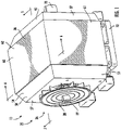
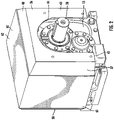
- Speed reducer 12 includes a generally rectangular cuboid housing 13 ( Fig. 5 ) with a first end surface or face 14 and an opposite second end surface or face 15. Oppositely facing side surfaces 16, an upper surface 17, and a lower surface 18 extend between the first end surface 14 and the second end surface 15.
- An input shaft 19 extends through the first end surface 14 into the housing 13 and an output shaft 20 extends through the second end surface 15 into the housing.
- the input shaft 19 and the output shaft 20 are operatively connected through various gears (not shown) within the housing 13.
- the input shaft 19, the output shaft 20, and the gears within the housing 13 are rotatably supported by bearings (not shown).
- the housing 13 may include oil therein to lubricate and cool the components within the housing.
- Housing 13 can, if desired, include a plurality of heat dissipation fins 21 disposed or mounted on the surface of the housing. As depicted, the fins 21 are mounted on the side surfaces 16 and the upper surface 17 of the housing. The fins 21 can be secured to the housing 13 along any of the surfaces and in any desired manner.
- the housing 13 may be formed of any desired material.
- the housing may be formed of steel or cast iron.
- the fins can be formed of any desired material.
- the fins 21 may be formed of a material that is different or dissimilar to the material from which the housing 13 is formed.
- the fins may be formed of a material having a high thermal conductivity such as aluminum, copper, alloys of such materials as well as any other material having similar or desired heat transfer and strength characteristics.
- Cooling system 25 includes a centrifugal fan 26 and an enclosure 35.
- the centrifugal fan 26 may be configured as a fan or blower and may be operatively connected to or driven by the input shaft 19 of the speed reducer 12.
- the centrifugal fan 26 has a rotatable impeller 28.
- the centrifugal fan 26 may further include a housing (not shown) such as one that includes a circular inlet (not shown) along the central axis of the impeller 28 and an outlet (not shown) spaced radially from the central axis.
- the fan 26 may be configured with straight blades so that the fan will operate as part of the cooling system 25 regardless of which direction the impeller 28 rotates. If the centrifugal fan is configured with a housing having an outlet, the outlet may be fluidly connected to duct work (not shown).
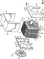
- the enclosure 35 includes an intake shroud or first end wall 36, an output shroud 50, and a cover 60 extending between the inlet shroud and the output shroud.
- the intake shroud 36 is generally U-shaped with a pair of spaced apart legs 37 interconnected by a connecting section 40 and partially enclosed by an intake wall or surface 43.
- Each of the legs 37 includes a flange portion 38 and an angled portion 39 extending between the flange portion and the intake wall 43.
- the connecting section 40 includes a flange portion 41 and an angled portion 42 extending between the connecting section and the intake wall 43.
- the intake wall 43 includes an opening in the form of a slot 44 extending upward from the lower surface 45 of the intake wall.
- the opening may take other forms such as, for example, being circular.
- a pair of mounting bosses 46 project inwardly (i.e., towards the housing 13 of speed reducer 12) from the intake wall 43 adjacent each of the legs 37. Fasteners (not shown) such as bolts extend through the bosses 46 and into the second end surface 15 of the housing 13 to secure the intake shroud 36 to the housing.
- the output shroud 50 can be generally similar to the intake shroud 36.
- the output shroud 50 is generally U-shaped with a pair of spaced apart legs 51 interconnected by a connecting section 54 and partially enclosed by an output wall or surface 57.
- Each of the legs 51 includes a flange portion 52 and an angled portion 53 extending between the flange portion and the intake wall 39.
- the connecting section 54 includes a flange portion 55 and an angled portion 56 extending between the connecting section and the output wall 57.
- the output wall or second end wall 57 includes an output opening 58 disposed adjacent the centrifugal fan 26 to permit air to be drawn by the fan from the output shroud 50.
- the output opening 58 of the output wall 57 may be configured to generally match the configuration (e.g., the diameter) of the circular inlet of the housing of the centrifugal fan to permit an airtight connection between the centrifugal fan and the output wall.
- the input shaft 19 extends through both the impeller 28 and the output opening 58 in the output wall 57.
- a pair of mounting bosses 59 project inwardly (i.e., towards the housing 13 of speed reducer 12) from the output wall 57 adjacent each of the legs 51. Fasteners (not shown) such as bolts extend through the bosses 59 and into the first end surface 14 of the housing 13 to secure the output shroud 50 to the housing.
- Cover 60 is generally U-shaped with a pair of spaced apart sidewalls 61 interconnected by a horizontal upper wall 62.
- the cover 60 is dimensioned to be mounted in an airtight manner on the flange portions 38, 41 of the intake shroud 36 and the flange portions 52, 55 of the output shroud 50.
- the legs 61 may be approximately the same length or slightly longer than the flange portions 38 of the legs 37 of the intake shroud 36 and the flange portions 52 of the legs 51 of the output shroud 50.
- horizontal connecting section 62 may be approximately the same length or slightly longer than the flange portion 41 of the connecting section 40 of the intake shroud 36 and the flange portion 55 of the connecting section 54 of the output shroud 50.
- the intake shroud 36, the output shroud 50, and the cover 60 are spaced from the housing 13 to define an air passage duct or air passage channel 70 that extends from the intake shroud to the centrifugal fan 26. More specifically, the air passage channel 70 includes a plurality of sections or segments from the intake shroud 36 to the output shroud 50.
- the slot 44 of the intake wall 43 defines the inlet or intake to the air passage channel 70.
- the first segment, depicted at 71, of the air passage channel 70 begins at the slot 44 of the intake wall 43 and extends to the side surfaces 16 and upper surface 17 of the housing 14.
- the first segment 71 is defined by the gap or space between the second end surface 15 of the housing 13 and the intake wall 43 of the intake shroud 36.
- the second segment 72 of the air passage channel 70 continues between and along the length of the side surfaces 16 of the housing 13 and the sidewalls 61 of the cover 60 and between and along the upper surface 17 of the housing and the upper wall 62 of the cover.
- the third segment 73 of the air passage channel 70 extends from the second segment 72 towards the output opening and is defined by the gap or space between the first end surface 14 of the housing 13 and the output wall 57 of the output shroud.
- the second or outlet end of the air passage channel 70 is defined by the circular opening 58 in the outlet wall 57 of the output shroud 50. If the housing 13 includes fins 21 thereon, the fins extend or project within the gap or air passage channel 70 along the sections of the channel depicted at 72 and 73. As best seen in Fig.
- the fins can extend entirely or essentially entirely across the air passage channel 70 so that the ends of the fins are positioned in close proximity to the cover 60.
- the distance between the housing 13 and the closure 35 may be reduced from that shown in the drawings if the housing does not include fins 21 thereon.
- the intake shroud 36 is mounted on the second end surface 15 of the housing 13 with fasteners (not shown) that extend through the bosses 46 in the intake shroud and into the housing 13.
- the output shroud 50 is mounted on the first end surface 14 of the housing 13 with fasteners (not shown) that extend through the bosses 59 in the output shroud and into the housing 13.
- the cover 60 is mounted so that it extends between the intake shroud 36 and the output shroud 50.
- the cover is disposed or mounted on the flange portions 38, 41 of the intake shroud 36 and the flange portions 52, 55 of the output flange 50 so that edges of the cover 60 overlap with and engage edges of the intake shroud 36 and the output shroud 50.
- the cover 60 may be secured to the housing 14 or to the intake shroud 36 and the output shroud 50 in any desired manner such as with fasteners (not shown).
- the enclosure 35 encloses the housing 13 and encloses substantially the first end surface 14, the second end surface 15, the side surfaces 16, and the upper surface 17.
- enclose substantially refers to the enclosure extending along the entire length or almost the entire length of each of the first end surface 14, the second end surface 15, the side surfaces 16, and the upper surface 17 of the housing.
- a rotational input to input shaft 19 is provided to drive the input shaft and ultimately rotate the output shaft 20.
- the rotation of the input shaft 19 causes the rotation of the impeller 28 of the centrifugal fan 26.
- the rotation of the impeller 28 creates a negative pressure or vacuum adjacent the opening 58 in the output wall 57 of the output shroud so that air is drawn through the slot 44 in the intake wall 43 of the intake shroud 36 and into the air passage channel 70.
- the air passes through the air passage channel 70, it passes over the housing 13 as well as the fins 21 to cool the speed reducer 12 before passing through the opening 58 in the output wall 57 of the output shroud 50.
- the mechanical drive system 10 may have any configuration that includes a shaft to drive the centrifugal fan 26.
- the centrifugal fan 26 is operatively connected to or driven by the input shaft 19 of the speed reducer 12, in other mechanical drive systems 10, the centrifugal fan 26 may be operatively connected to or driven by any shaft that is rotating the fastest.
- cooling system 25 may be used with any system having a housing for which cooling is desired regardless of whether the system includes a rotating shaft.
- power to the centrifugal fan 26 may be provided in another manner such as with an electric drive.
Landscapes
- Engineering & Computer Science (AREA)
- General Engineering & Computer Science (AREA)
- Mechanical Engineering (AREA)
- Physics & Mathematics (AREA)
- Thermal Sciences (AREA)
- Power Engineering (AREA)
- General Details Of Gearings (AREA)
- Structures Of Non-Positive Displacement Pumps (AREA)
Claims (8)
- Mechanisches Antriebssystem (10), umfassend:eine mechanische Antriebskomponente (12), wobei die mechanische Antriebskomponente ein Gehäuse (13) und eine erste drehbare Welle (19) aufweist, die in dem Gehäuse (13) getragen wird, wobei das Gehäuse (13) eine erste Endfläche (14), eine zweite Endfläche (15), ein Paar beabstandeter Seitenflächen (16), die sich zwischen der ersten und zweiten Endfläche (14; 15) erstrecken, und eine obere Fläche (17) aufweist, die sich zwischen der ersten und zweiten Endfläche (14; 15) erstreckt;eine Verkleidung (35), die an dem Gehäuse (13) angeordnet ist, wobei die Verkleidung (35) eine erste Endwand (36), eine zweite Endwand (57), ein Paar beabstandeter Seitenwände (61), die sich zwischen der ersten und zweiten Endwand (36; 57) erstrecken, und eine obere Wand (62) aufweist, die sich zwischen der ersten und zweiten Endwand (36; 57) erstreckt, wobei das Paar beabstandeter Seitenwände (61) und die obere Wand (62) eine Abdeckung (60) bilden, die im Wesentlichen U-förmig ist, die zweite Endwand (57) eine Auslassöffnung (58) darin aufweist, durch welche sich die erste drehbare Welle (19) der mechanischen Antriebskomponente erstreckt, die erste Endwand (36) eine Einlassöffnung (44) darin aufweist, die erste und zweite Endfläche (14; 15), das Paar beabstandeter Seitenflächen (16) und die obere Fläche (17) des Gehäuses (13) der mechanischen Antriebskomponente, zusammen mit dem Paar beabstandeter Seitenwände (61) und die obere Wand (62) der Verkleidung (35) zwischen sich einen Luftdurchgangskanal (70) definieren, der sich von der Einlassöffnung (44) zu der Auslassöffnung (58) erstreckt;ein Zentrifugalgebläse (26), das ein drehbares Laufrad (28) aufweist, das an der Auslassöffnung (58) der Verkleidung (35) ausgerichtet ist und mit ihr in Fluidkommunikation steht, wobei die erste drehbare Welle (19) betriebswirksam an das Laufrad (28) gekoppelt ist, gekennzeichnet durcheine Vielzahl von Wärmeableitungsrippen (21), die an dem Paar beabstandeter Seitenflächen (16) und der oberen Fläche (17) des Gehäuses (13) befestigt ist, wobei jede der Vielzahl von Rippen (21) eine flache rechteckige Form aufweist, die in einer Richtung eines Luftstroms (72) durch den Luftdurchgangskanal (70) ausgerichtet ist, wobei sich die Vielzahl von Rippen (21) in und durch den gesamten Luftdurchgangskanal (70) erstreckt, sodass äußere Enden der Rippen nahe der Abdeckung (60) positioniert sind; unddas Zentrifugalgebläse (26), das betrieben wird, um einen negativen Druck oder ein Vakuum benachbart zu der Auslassöffnung (58) zu erzeugen, sodass Luft durch die Einlassöffnung (44), durch den Luftdurchgangskanal (70) und über die Vielzahl von Wärmeableitungsrippen (21) gesaugt und durch die Auslassöffnung (58) ausgegeben wird.
- System nach Anspruch 1, wobei das Gehäuse (13) aus einem ersten Material hergestellt ist und die Wärmeableitungsrippen (21) aus einem zweiten Material hergestellt sind, das sich von dem ersten Material unterscheidet.
- System nach Anspruch 1, wobei die Verkleidung (35) die erste Endfläche (14), die zweite Endfläche (15), das Paar beabstandeter Seitenflächen (16) und die obere Fläche (17) verkleidet.
- System nach Anspruch 3, wobei das Gehäuse (13) ferner eine untere Fläche (18) beinhaltet und die Verkleidung (35) dazu konfiguriert ist, das gesamte Gehäuse (13) mit Ausnahme der unteren Fläche (18) zu verkleiden.
- System nach Anspruch 1, wobei sich die beabstandeten Seitenwände (61) und die obere Wand (62) mit der ersten und zweiten Endwand (36; 57) überlappen.
- System nach Anspruch 1, wobei die Verkleidung (35) ferner dazu konfiguriert ist, das Gehäuse (13) zu verkleiden.
- System nach Anspruch 1, wobei die mechanische Antriebskomponente (12) ferner Folgendes beinhaltet:
eine zweite drehbare Welle (20), die in dem Gehäuse (13) getragen wird, wobei die erste Welle (19) betriebswirksam mit der zweiten Welle (20) verbunden ist, sich die erste Welle durch die erste Endfläche (14) erstreckt und sich die zweite Welle (20) durch die zweite Endfläche (15) erstreckt; wobei sich die zweite Welle durch die Einlassöffnung (44) in die zweite Endwand (57) erstreckt, und die zweite Endwand (57) eine Vielzahl von Kanten aufweist, wobei jede Kante benachbart zu einer der beabstandeten Seitenwände (61) und der oberen Wand (62) ist, wobei die Einlassöffnung (44) von jeder Kante der zweiten Wand (57) beabstandet ist. - System nach Anspruch 1, wobei sich jede der ersten und zweiten Endwand (36; 57) zu jeder der beabstandeten Seitenwände (61) und der oberen Wand (62) erstreckt.
Applications Claiming Priority (1)
| Application Number | Priority Date | Filing Date | Title |
|---|---|---|---|
| US16/033,992 US10876800B2 (en) | 2018-07-12 | 2018-07-12 | Mechanical system with cooling apparatus |
Publications (2)
| Publication Number | Publication Date |
|---|---|
| EP3594534A1 EP3594534A1 (de) | 2020-01-15 |
| EP3594534B1 true EP3594534B1 (de) | 2023-01-04 |
Family
ID=67226164
Family Applications (1)
| Application Number | Title | Priority Date | Filing Date |
|---|---|---|---|
| EP19185529.5A Active EP3594534B1 (de) | 2018-07-12 | 2019-07-10 | Mechanisches system mit kühlvorrichtung |
Country Status (2)
| Country | Link |
|---|---|
| US (1) | US10876800B2 (de) |
| EP (1) | EP3594534B1 (de) |
Families Citing this family (2)
| Publication number | Priority date | Publication date | Assignee | Title |
|---|---|---|---|---|
| US11466768B2 (en) * | 2018-12-31 | 2022-10-11 | Abb Schweiz Ag | Methods and systems for cooling transmissions |
| CN121229608A (zh) * | 2025-12-02 | 2025-12-30 | 江西昌兴航空装备股份有限公司 | 一种用于航空装备的具有改进型散热风扇的变速箱组件 |
Citations (2)
| Publication number | Priority date | Publication date | Assignee | Title |
|---|---|---|---|---|
| FR1428418A (fr) * | 1965-02-15 | 1966-02-11 | Tsnii Tekhnologh I Mash | Procédé de refroidissement par air de réducteurs à engrenages et autres appareils similaires |
| JP2002218704A (ja) * | 2001-01-22 | 2002-08-02 | Mitsubishi Electric Corp | 全閉外扇形電動機 |
Family Cites Families (20)
| Publication number | Priority date | Publication date | Assignee | Title |
|---|---|---|---|---|
| US1564742A (en) * | 1923-10-22 | 1925-12-08 | Cleveland Worm And Gear Compan | Worm-gear reduction unit |
| US1991618A (en) * | 1930-11-03 | 1935-02-19 | Borg Warner | Radiating type oil pan for internal combustion engines |
| US2147391A (en) * | 1935-10-15 | 1939-02-14 | Cleveland Worm And Gear Compan | Reduction gear |
| DE858920C (de) * | 1943-09-30 | 1952-12-11 | Zahnraederfabrik Augsburg Vorm | Schneckengetriebe mit Luftstromkuehlung |
| US3353591A (en) * | 1965-02-15 | 1967-11-21 | Tsnii Teknologii I Mash | Apparatus for cooling gear reduction units |
| DE1298819B (de) * | 1966-07-21 | 1969-07-03 | Wuelfel Eisenwerk | Kuehlvorrichtung fuer Umlaufraedergetriebe |
| US3921603A (en) | 1974-03-18 | 1975-11-25 | Caterpillar Tractor Co | Centrifugal fan cooling system |
| DE3318199A1 (de) * | 1982-06-03 | 1984-11-22 | Licentia Patent-Verwaltungs-Gmbh, 6000 Frankfurt | Getriebegehaeuse fuer elektrowerkzeuge |
| US4633938A (en) * | 1985-08-08 | 1987-01-06 | The Falk Corporation | Gear drive cooling system |
| US4949524A (en) | 1987-09-16 | 1990-08-21 | The Standard Products Company | Flange finisher with weatherstrip |
| US4872502A (en) * | 1987-09-25 | 1989-10-10 | The Falk Company | Air cooling of enclosed gear drives |
| US6155135A (en) * | 1998-11-23 | 2000-12-05 | American Axle & Manufacturing, Inc. | Drive unit with lubricant cooling cover |
| US20080302880A1 (en) * | 2007-06-08 | 2008-12-11 | Dreison International, Inc. | Motor cooling device |
| US20090038780A1 (en) * | 2007-08-10 | 2009-02-12 | Kechuan Kevin Liu | Pumpless liquid cooling system |
| DE102009014315B4 (de) * | 2009-03-25 | 2018-01-25 | Sew-Eurodrive Gmbh & Co Kg | Getriebe |
| US9599406B2 (en) * | 2010-01-27 | 2017-03-21 | Rexnord Industries, Llc | Transmission having a fluid cooling shroud |
| CN103518078B (zh) | 2011-03-17 | 2016-11-02 | 索尤若驱动有限及两合公司 | 减速器装置 |
| JP6063288B2 (ja) | 2013-02-15 | 2017-01-18 | 住友重機械工業株式会社 | 動力伝達装置 |
| ES2824260T3 (es) * | 2015-04-23 | 2021-05-11 | Flender Gmbh | Deflector de aire para una transmisión y transmisión con un deflector de aire |
| US20180262094A1 (en) * | 2017-03-07 | 2018-09-13 | Peopleflo Manufacturing, Inc. | Magnetically coupled fan assembly and electric rotary motor combination |
-
2018
- 2018-07-12 US US16/033,992 patent/US10876800B2/en not_active Expired - Fee Related
-
2019
- 2019-07-10 EP EP19185529.5A patent/EP3594534B1/de active Active
Patent Citations (2)
| Publication number | Priority date | Publication date | Assignee | Title |
|---|---|---|---|---|
| FR1428418A (fr) * | 1965-02-15 | 1966-02-11 | Tsnii Tekhnologh I Mash | Procédé de refroidissement par air de réducteurs à engrenages et autres appareils similaires |
| JP2002218704A (ja) * | 2001-01-22 | 2002-08-02 | Mitsubishi Electric Corp | 全閉外扇形電動機 |
Also Published As
| Publication number | Publication date |
|---|---|
| EP3594534A1 (de) | 2020-01-15 |
| US20200018558A1 (en) | 2020-01-16 |
| US10876800B2 (en) | 2020-12-29 |
Similar Documents
| Publication | Publication Date | Title |
|---|---|---|
| US8215928B2 (en) | Foil gas bearing supported high temperature centrifugal blower and method for cooling thereof | |
| EP2752976A2 (de) | Verbesserte Kühlung von umschlossenen, luftgekühlten Hochleistungsmotoren | |
| US8007241B2 (en) | Bi-directional cooling fan | |
| JP2018526574A (ja) | 冷却体を備えたターボファン | |
| JP6786823B2 (ja) | 遠心流体機械及び遠心送風機及び遠心圧縮機 | |
| EP3113332A1 (de) | Motor mit wärmeableitungsstruktur | |
| EP3594534B1 (de) | Mechanisches system mit kühlvorrichtung | |
| US11261879B2 (en) | Fluid machine | |
| EP3125411A1 (de) | Verbesserte motorstruktur | |
| US20130022443A1 (en) | Fan motor cooling | |
| JP6151382B2 (ja) | 多段電動遠心圧縮機 | |
| USRE25569E (en) | Multistage fan | |
| US10876546B2 (en) | Centrifugal compressor | |
| JPH01267392A (ja) | ターボ真空ポンプ | |
| JP2014050133A (ja) | ロータ、電動機及び過給機 | |
| US20080302880A1 (en) | Motor cooling device | |
| US10797565B2 (en) | Motor with inner fan | |
| JP2015081596A (ja) | 送風装置 | |
| EP4198318B1 (de) | Elektrischer ventilator | |
| US20240426341A1 (en) | Magnetic thrust bearing with pumping effect | |
| CN110630536A (zh) | 风扇和电力机械总成及其方法 | |
| JP6785038B2 (ja) | 流体機械 | |
| US10385873B2 (en) | Fan | |
| JP6649030B2 (ja) | 軸流ファン | |
| US20200274417A1 (en) | Servo air-kool system |
Legal Events
| Date | Code | Title | Description |
|---|---|---|---|
| PUAI | Public reference made under article 153(3) epc to a published international application that has entered the european phase |
Free format text: ORIGINAL CODE: 0009012 |
|
| STAA | Information on the status of an ep patent application or granted ep patent |
Free format text: STATUS: THE APPLICATION HAS BEEN PUBLISHED |
|
| AK | Designated contracting states |
Kind code of ref document: A1 Designated state(s): AL AT BE BG CH CY CZ DE DK EE ES FI FR GB GR HR HU IE IS IT LI LT LU LV MC MK MT NL NO PL PT RO RS SE SI SK SM TR |
|
| AX | Request for extension of the european patent |
Extension state: BA ME |
|
| STAA | Information on the status of an ep patent application or granted ep patent |
Free format text: STATUS: REQUEST FOR EXAMINATION WAS MADE |
|
| 17P | Request for examination filed |
Effective date: 20200714 |
|
| RBV | Designated contracting states (corrected) |
Designated state(s): AL AT BE BG CH CY CZ DE DK EE ES FI FR GB GR HR HU IE IS IT LI LT LU LV MC MK MT NL NO PL PT RO RS SE SI SK SM TR |
|
| STAA | Information on the status of an ep patent application or granted ep patent |
Free format text: STATUS: EXAMINATION IS IN PROGRESS |
|
| 17Q | First examination report despatched |
Effective date: 20201021 |
|
| REG | Reference to a national code |
Ref country code: DE Ref legal event code: R079 Ref document number: 602019023877 Country of ref document: DE Free format text: PREVIOUS MAIN CLASS: F16H0057040000 Ipc: H02K0005180000 |
|
| RIC1 | Information provided on ipc code assigned before grant |
Ipc: F16H 57/04 20100101ALI20210823BHEP Ipc: H02K 9/14 20060101ALI20210823BHEP Ipc: H02K 9/06 20060101ALI20210823BHEP Ipc: H02K 5/18 20060101AFI20210823BHEP |
|
| GRAP | Despatch of communication of intention to grant a patent |
Free format text: ORIGINAL CODE: EPIDOSNIGR1 |
|
| STAA | Information on the status of an ep patent application or granted ep patent |
Free format text: STATUS: GRANT OF PATENT IS INTENDED |
|
| INTG | Intention to grant announced |
Effective date: 20211007 |
|
| GRAS | Grant fee paid |
Free format text: ORIGINAL CODE: EPIDOSNIGR3 |
|
| GRAA | (expected) grant |
Free format text: ORIGINAL CODE: 0009210 |
|
| STAA | Information on the status of an ep patent application or granted ep patent |
Free format text: STATUS: THE PATENT HAS BEEN GRANTED |
|
| AK | Designated contracting states |
Kind code of ref document: B1 Designated state(s): AL AT BE BG CH CY CZ DE DK EE ES FI FR GB GR HR HU IE IS IT LI LT LU LV MC MK MT NL NO PL PT RO RS SE SI SK SM TR |
|
| REG | Reference to a national code |
Ref country code: GB Ref legal event code: FG4D |
|
| REG | Reference to a national code |
Ref country code: CH Ref legal event code: EP |
|
| REG | Reference to a national code |
Ref country code: AT Ref legal event code: REF Ref document number: 1542639 Country of ref document: AT Kind code of ref document: T Effective date: 20230115 |
|
| REG | Reference to a national code |
Ref country code: DE Ref legal event code: R096 Ref document number: 602019023877 Country of ref document: DE |
|
| REG | Reference to a national code |
Ref country code: IE Ref legal event code: FG4D |
|
| REG | Reference to a national code |
Ref country code: LT Ref legal event code: MG9D |
|
| REG | Reference to a national code |
Ref country code: NL Ref legal event code: MP Effective date: 20230104 |
|
| REG | Reference to a national code |
Ref country code: AT Ref legal event code: MK05 Ref document number: 1542639 Country of ref document: AT Kind code of ref document: T Effective date: 20230104 |
|
| PG25 | Lapsed in a contracting state [announced via postgrant information from national office to epo] |
Ref country code: NL Free format text: LAPSE BECAUSE OF FAILURE TO SUBMIT A TRANSLATION OF THE DESCRIPTION OR TO PAY THE FEE WITHIN THE PRESCRIBED TIME-LIMIT Effective date: 20230104 |
|
| PG25 | Lapsed in a contracting state [announced via postgrant information from national office to epo] |
Ref country code: RS Free format text: LAPSE BECAUSE OF FAILURE TO SUBMIT A TRANSLATION OF THE DESCRIPTION OR TO PAY THE FEE WITHIN THE PRESCRIBED TIME-LIMIT Effective date: 20230104 Ref country code: PT Free format text: LAPSE BECAUSE OF FAILURE TO SUBMIT A TRANSLATION OF THE DESCRIPTION OR TO PAY THE FEE WITHIN THE PRESCRIBED TIME-LIMIT Effective date: 20230504 Ref country code: NO Free format text: LAPSE BECAUSE OF FAILURE TO SUBMIT A TRANSLATION OF THE DESCRIPTION OR TO PAY THE FEE WITHIN THE PRESCRIBED TIME-LIMIT Effective date: 20230404 Ref country code: LV Free format text: LAPSE BECAUSE OF FAILURE TO SUBMIT A TRANSLATION OF THE DESCRIPTION OR TO PAY THE FEE WITHIN THE PRESCRIBED TIME-LIMIT Effective date: 20230104 Ref country code: LT Free format text: LAPSE BECAUSE OF FAILURE TO SUBMIT A TRANSLATION OF THE DESCRIPTION OR TO PAY THE FEE WITHIN THE PRESCRIBED TIME-LIMIT Effective date: 20230104 Ref country code: HR Free format text: LAPSE BECAUSE OF FAILURE TO SUBMIT A TRANSLATION OF THE DESCRIPTION OR TO PAY THE FEE WITHIN THE PRESCRIBED TIME-LIMIT Effective date: 20230104 Ref country code: ES Free format text: LAPSE BECAUSE OF FAILURE TO SUBMIT A TRANSLATION OF THE DESCRIPTION OR TO PAY THE FEE WITHIN THE PRESCRIBED TIME-LIMIT Effective date: 20230104 Ref country code: AT Free format text: LAPSE BECAUSE OF FAILURE TO SUBMIT A TRANSLATION OF THE DESCRIPTION OR TO PAY THE FEE WITHIN THE PRESCRIBED TIME-LIMIT Effective date: 20230104 |
|
| PG25 | Lapsed in a contracting state [announced via postgrant information from national office to epo] |
Ref country code: SE Free format text: LAPSE BECAUSE OF FAILURE TO SUBMIT A TRANSLATION OF THE DESCRIPTION OR TO PAY THE FEE WITHIN THE PRESCRIBED TIME-LIMIT Effective date: 20230104 Ref country code: PL Free format text: LAPSE BECAUSE OF FAILURE TO SUBMIT A TRANSLATION OF THE DESCRIPTION OR TO PAY THE FEE WITHIN THE PRESCRIBED TIME-LIMIT Effective date: 20230104 Ref country code: IS Free format text: LAPSE BECAUSE OF FAILURE TO SUBMIT A TRANSLATION OF THE DESCRIPTION OR TO PAY THE FEE WITHIN THE PRESCRIBED TIME-LIMIT Effective date: 20230504 Ref country code: GR Free format text: LAPSE BECAUSE OF FAILURE TO SUBMIT A TRANSLATION OF THE DESCRIPTION OR TO PAY THE FEE WITHIN THE PRESCRIBED TIME-LIMIT Effective date: 20230405 Ref country code: FI Free format text: LAPSE BECAUSE OF FAILURE TO SUBMIT A TRANSLATION OF THE DESCRIPTION OR TO PAY THE FEE WITHIN THE PRESCRIBED TIME-LIMIT Effective date: 20230104 |
|
| REG | Reference to a national code |
Ref country code: DE Ref legal event code: R097 Ref document number: 602019023877 Country of ref document: DE |
|
| PG25 | Lapsed in a contracting state [announced via postgrant information from national office to epo] |
Ref country code: SM Free format text: LAPSE BECAUSE OF FAILURE TO SUBMIT A TRANSLATION OF THE DESCRIPTION OR TO PAY THE FEE WITHIN THE PRESCRIBED TIME-LIMIT Effective date: 20230104 Ref country code: RO Free format text: LAPSE BECAUSE OF FAILURE TO SUBMIT A TRANSLATION OF THE DESCRIPTION OR TO PAY THE FEE WITHIN THE PRESCRIBED TIME-LIMIT Effective date: 20230104 Ref country code: EE Free format text: LAPSE BECAUSE OF FAILURE TO SUBMIT A TRANSLATION OF THE DESCRIPTION OR TO PAY THE FEE WITHIN THE PRESCRIBED TIME-LIMIT Effective date: 20230104 Ref country code: DK Free format text: LAPSE BECAUSE OF FAILURE TO SUBMIT A TRANSLATION OF THE DESCRIPTION OR TO PAY THE FEE WITHIN THE PRESCRIBED TIME-LIMIT Effective date: 20230104 Ref country code: CZ Free format text: LAPSE BECAUSE OF FAILURE TO SUBMIT A TRANSLATION OF THE DESCRIPTION OR TO PAY THE FEE WITHIN THE PRESCRIBED TIME-LIMIT Effective date: 20230104 |
|
| PLBE | No opposition filed within time limit |
Free format text: ORIGINAL CODE: 0009261 |
|
| STAA | Information on the status of an ep patent application or granted ep patent |
Free format text: STATUS: NO OPPOSITION FILED WITHIN TIME LIMIT |
|
| REG | Reference to a national code |
Ref country code: DE Ref legal event code: R082 Ref document number: 602019023877 Country of ref document: DE Representative=s name: SEEMANN & PARTNER PATENTANWAELTE MBB, DE Ref country code: DE Ref legal event code: R081 Ref document number: 602019023877 Country of ref document: DE Owner name: DODGE INDUSTRIAL, INC. (N.D.GES.D.STAATES DELA, US Free format text: FORMER OWNER: ABB SCHWEIZ AG, BADEN, CH |
|
| PG25 | Lapsed in a contracting state [announced via postgrant information from national office to epo] |
Ref country code: SK Free format text: LAPSE BECAUSE OF FAILURE TO SUBMIT A TRANSLATION OF THE DESCRIPTION OR TO PAY THE FEE WITHIN THE PRESCRIBED TIME-LIMIT Effective date: 20230104 |
|
| 26N | No opposition filed |
Effective date: 20231005 |
|
| PG25 | Lapsed in a contracting state [announced via postgrant information from national office to epo] |
Ref country code: SI Free format text: LAPSE BECAUSE OF FAILURE TO SUBMIT A TRANSLATION OF THE DESCRIPTION OR TO PAY THE FEE WITHIN THE PRESCRIBED TIME-LIMIT Effective date: 20230104 |
|
| REG | Reference to a national code |
Ref country code: DE Ref legal event code: R119 Ref document number: 602019023877 Country of ref document: DE |
|
| PG25 | Lapsed in a contracting state [announced via postgrant information from national office to epo] |
Ref country code: MC Free format text: LAPSE BECAUSE OF FAILURE TO SUBMIT A TRANSLATION OF THE DESCRIPTION OR TO PAY THE FEE WITHIN THE PRESCRIBED TIME-LIMIT Effective date: 20230104 |
|
| PG25 | Lapsed in a contracting state [announced via postgrant information from national office to epo] |
Ref country code: MC Free format text: LAPSE BECAUSE OF FAILURE TO SUBMIT A TRANSLATION OF THE DESCRIPTION OR TO PAY THE FEE WITHIN THE PRESCRIBED TIME-LIMIT Effective date: 20230104 |
|
| REG | Reference to a national code |
Ref country code: CH Ref legal event code: PL |
|
| REG | Reference to a national code |
Ref country code: BE Ref legal event code: MM Effective date: 20230731 |
|
| PG25 | Lapsed in a contracting state [announced via postgrant information from national office to epo] |
Ref country code: LU Free format text: LAPSE BECAUSE OF NON-PAYMENT OF DUE FEES Effective date: 20230710 |
|
| GBPC | Gb: european patent ceased through non-payment of renewal fee |
Effective date: 20230710 |
|
| PG25 | Lapsed in a contracting state [announced via postgrant information from national office to epo] |
Ref country code: LU Free format text: LAPSE BECAUSE OF NON-PAYMENT OF DUE FEES Effective date: 20230710 |
|
| REG | Reference to a national code |
Ref country code: IE Ref legal event code: MM4A |
|
| PG25 | Lapsed in a contracting state [announced via postgrant information from national office to epo] |
Ref country code: DE Free format text: LAPSE BECAUSE OF NON-PAYMENT OF DUE FEES Effective date: 20240201 Ref country code: CH Free format text: LAPSE BECAUSE OF NON-PAYMENT OF DUE FEES Effective date: 20230731 Ref country code: GB Free format text: LAPSE BECAUSE OF NON-PAYMENT OF DUE FEES Effective date: 20230710 |
|
| PG25 | Lapsed in a contracting state [announced via postgrant information from national office to epo] |
Ref country code: IT Free format text: LAPSE BECAUSE OF FAILURE TO SUBMIT A TRANSLATION OF THE DESCRIPTION OR TO PAY THE FEE WITHIN THE PRESCRIBED TIME-LIMIT Effective date: 20230104 Ref country code: FR Free format text: LAPSE BECAUSE OF NON-PAYMENT OF DUE FEES Effective date: 20230731 Ref country code: BE Free format text: LAPSE BECAUSE OF NON-PAYMENT OF DUE FEES Effective date: 20230731 |
|
| PG25 | Lapsed in a contracting state [announced via postgrant information from national office to epo] |
Ref country code: IE Free format text: LAPSE BECAUSE OF NON-PAYMENT OF DUE FEES Effective date: 20230710 |
|
| PG25 | Lapsed in a contracting state [announced via postgrant information from national office to epo] |
Ref country code: IE Free format text: LAPSE BECAUSE OF NON-PAYMENT OF DUE FEES Effective date: 20230710 |
|
| PG25 | Lapsed in a contracting state [announced via postgrant information from national office to epo] |
Ref country code: BG Free format text: LAPSE BECAUSE OF FAILURE TO SUBMIT A TRANSLATION OF THE DESCRIPTION OR TO PAY THE FEE WITHIN THE PRESCRIBED TIME-LIMIT Effective date: 20230104 |
|
| PG25 | Lapsed in a contracting state [announced via postgrant information from national office to epo] |
Ref country code: BG Free format text: LAPSE BECAUSE OF FAILURE TO SUBMIT A TRANSLATION OF THE DESCRIPTION OR TO PAY THE FEE WITHIN THE PRESCRIBED TIME-LIMIT Effective date: 20230104 |
|
| PG25 | Lapsed in a contracting state [announced via postgrant information from national office to epo] |
Ref country code: CY Free format text: LAPSE BECAUSE OF FAILURE TO SUBMIT A TRANSLATION OF THE DESCRIPTION OR TO PAY THE FEE WITHIN THE PRESCRIBED TIME-LIMIT; INVALID AB INITIO Effective date: 20190710 |
|
| PG25 | Lapsed in a contracting state [announced via postgrant information from national office to epo] |
Ref country code: HU Free format text: LAPSE BECAUSE OF FAILURE TO SUBMIT A TRANSLATION OF THE DESCRIPTION OR TO PAY THE FEE WITHIN THE PRESCRIBED TIME-LIMIT; INVALID AB INITIO Effective date: 20190710 |
|
| PG25 | Lapsed in a contracting state [announced via postgrant information from national office to epo] |
Ref country code: TR Free format text: LAPSE BECAUSE OF FAILURE TO SUBMIT A TRANSLATION OF THE DESCRIPTION OR TO PAY THE FEE WITHIN THE PRESCRIBED TIME-LIMIT Effective date: 20230104 |