EP3594085B1 - Verfahren und vorrichtung zum auflösen der fahrstrasse bei computerstellwerk und computerspeichermedium - Google Patents
Verfahren und vorrichtung zum auflösen der fahrstrasse bei computerstellwerk und computerspeichermedium Download PDFInfo
- Publication number
- EP3594085B1 EP3594085B1 EP18877161.2A EP18877161A EP3594085B1 EP 3594085 B1 EP3594085 B1 EP 3594085B1 EP 18877161 A EP18877161 A EP 18877161A EP 3594085 B1 EP3594085 B1 EP 3594085B1
- Authority
- EP
- European Patent Office
- Prior art keywords
- judging
- section
- current locked
- locked section
- yes
- Prior art date
- Legal status (The legal status is an assumption and is not a legal conclusion. Google has not performed a legal analysis and makes no representation as to the accuracy of the status listed.)
- Active
Links
Images


Classifications
-
- B—PERFORMING OPERATIONS; TRANSPORTING
- B61—RAILWAYS
- B61L—GUIDING RAILWAY TRAFFIC; ENSURING THE SAFETY OF RAILWAY TRAFFIC
- B61L23/00—Control, warning or like safety means along the route or between vehicles or trains
- B61L23/22—Control, warning or like safety means along the route or between vehicles or trains for controlling traffic in two directions over the same pair of rails
- B61L23/30—Control, warning or like safety means along the route or between vehicles or trains for controlling traffic in two directions over the same pair of rails using automatic section blocking
-
- B—PERFORMING OPERATIONS; TRANSPORTING
- B61—RAILWAYS
- B61L—GUIDING RAILWAY TRAFFIC; ENSURING THE SAFETY OF RAILWAY TRAFFIC
- B61L23/00—Control, warning or like safety means along the route or between vehicles or trains
-
- B—PERFORMING OPERATIONS; TRANSPORTING
- B61—RAILWAYS
- B61L—GUIDING RAILWAY TRAFFIC; ENSURING THE SAFETY OF RAILWAY TRAFFIC
- B61L19/00—Arrangements for interlocking between points and signals by means of a single interlocking device, e.g. central control
- B61L19/06—Interlocking devices having electrical operation
-
- B—PERFORMING OPERATIONS; TRANSPORTING
- B61—RAILWAYS
- B61L—GUIDING RAILWAY TRAFFIC; ENSURING THE SAFETY OF RAILWAY TRAFFIC
- B61L23/00—Control, warning or like safety means along the route or between vehicles or trains
- B61L23/08—Control, warning or like safety means along the route or between vehicles or trains for controlling traffic in one direction only
- B61L23/14—Control, warning or like safety means along the route or between vehicles or trains for controlling traffic in one direction only automatically operated
-
- B—PERFORMING OPERATIONS; TRANSPORTING
- B61—RAILWAYS
- B61L—GUIDING RAILWAY TRAFFIC; ENSURING THE SAFETY OF RAILWAY TRAFFIC
- B61L27/00—Central railway traffic control systems; Trackside control; Communication systems specially adapted therefor
-
- B—PERFORMING OPERATIONS; TRANSPORTING
- B61—RAILWAYS
- B61L—GUIDING RAILWAY TRAFFIC; ENSURING THE SAFETY OF RAILWAY TRAFFIC
- B61L27/00—Central railway traffic control systems; Trackside control; Communication systems specially adapted therefor
- B61L27/20—Trackside control of safe travel of vehicle or train, e.g. braking curve calculation
-
- B—PERFORMING OPERATIONS; TRANSPORTING
- B61—RAILWAYS
- B61L—GUIDING RAILWAY TRAFFIC; ENSURING THE SAFETY OF RAILWAY TRAFFIC
- B61L27/00—Central railway traffic control systems; Trackside control; Communication systems specially adapted therefor
- B61L27/40—Handling position reports or trackside vehicle data
-
- B—PERFORMING OPERATIONS; TRANSPORTING
- B61—RAILWAYS
- B61L—GUIDING RAILWAY TRAFFIC; ENSURING THE SAFETY OF RAILWAY TRAFFIC
- B61L19/00—Arrangements for interlocking between points and signals by means of a single interlocking device, e.g. central control
- B61L19/06—Interlocking devices having electrical operation
- B61L2019/065—Interlocking devices having electrical operation with electronic means
Definitions
- the present disclosure relates to a field of automatic control technologies, and to a method and apparatus for route release in Computer Interlocking (CI), and a computer storage medium.
- CI Computer Interlocking
- CTCS-2 and CTCS-3 train control systems have been practically applied to many passenger lines, which improves the automation level of train control and reduces a running interval of trains.
- switches in the train running direction have to be locked at specified positions, and the switches are not allowed to rotate after being locked.
- the switches are locked in a mode of route locking section, i.e., after a route is locked, the switches in the route section are not allowed to rotate.
- the length of section route locking time is closely related to the running interval of the trains, and timely release of the route section can prepare routes for following trains as soon as possible, so that the running interval can be greatly shortened.
- route release in CI is generally designed in a sectional release mode.
- the section in the locked route should be automatically released along with normal running of the train, and the section which the train passes can be immediately provided to other trains for use, so as to improve running efficiency.
- CI needs to determine by effective means whether the train normally passes through the locked section. Therefore, those skilled in the art urgently need to research and develop a method for accurately judging whether a running train normally passes through the locked section so as to maximize driving efficiency when ensuring driving safety.
- the present disclosure is intended to solve the technical problem of providing a method and apparatus for route release in CI and a computer storage medium, and solves the problem in the prior art that a train is misjudged normally passes through a locked section when some track circuits are abnormal.
- the invention is defined in the independent claims.
- the present disclosure provides a method for route release in CI, including judging whether a train normally drives into a current locked section; if a judging result is yes, judging whether the train drives away from the current locked section; if a judging result is yes, judging whether a rear section of the current locked section is released; and if a judging result is yes, releasing the current locked section.
- the present disclosure further provides a computer storage medium including a computer executing instruction.
- the data processing device executes steps of: judging whether a train normally drives into a current locked section; if a judging result is yes, judging whether the train drives away from the current locked section; if a judging result is yes, judging whether a rear section of the current locked section is released; and if a judging result is yes, releasing the current locked section.
- the present disclosure further provides an apparatus for route release in CI, including: a first judging unit, which is used for judging whether a train normally drives into a current locked section; a second judging unit, which is used for judging whether the train drives away from the current locked section when a judging result of the first judging unit is yes; a third judging unit, which is used for judging whether a rear section of the current locked section is released when a judging result of the second judging unit is yes; and a releasing unit, which is used for releasing the current locked section when a judging result of the third judging unit is yes.
- the method and apparatus for route release in CI and the computer storage medium at least have following advantages: it is determined whether the train normally passes through the locked section in a three-point section check mode, i.e., only when the train normally drives into the locked section and then drives away from the locked section, the locked section can be allowed to be released, thereby avoiding misjudgment when the track circuits are abnormal; and whether the train normally passes through the locked section can be accurately determined by a state of front section and states of the rear section and the current section (the current locked section), thereby maximizing driving efficiency when ensuring driving safety.
- CN 106 828 541 A relates to a train operation control system.
- FIG. 1 is a flow chart of Embodiment I of a method for route release in CI, as provided in detailed description of the present disclosure. As shown in FIG. 1 , if a train normally drives into a current locked section and drives away from the current locked section, the current locked section is released.
- the method for route release in CI includes:
- the current locked section can be released, thereby implementing automatic release of the locked section, preventing misjudgment caused by abnormality of track circuits and maximizing running efficiency when ensuring driving safety.
- FIG. 2 is a flow chart of Embodiment II of a method for route release in CI, as provided in detailed description of the present disclosure. As shown in FIG. 2 , if the train does not normally drive into the current locked section or the train does not normally drive away from the current locked section, the current locked section is kept in a locked state.
- the method for route release in CI further includes: S105: if the judging result is no, keeping the current locked section in the locked state.
- the current locked section still cannot be released so as to avoid driving danger.
- the current locked section can be released.
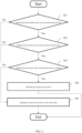
- FIG. 3 is a flow chart of Embodiment III of a method for route release in CI, as provided in detailed description of the present disclosure. As shown in FIG. 3 , only when a state of the rear section is turned into an idle state from an occupied state and the state of the current locked section is turned into an occupied state from an idle state, it can be determined that the train normally drives into the current locked section.
- step S101 particularly includes:
- step S1012 if the judging result is yes, it is determined that the train normally drives into the current locked section. In the specific embodiment of the present disclosure, only when the current locked section is turned into the occupied state from the idle state and the rear section is turned into the idle state from the occupied state, it can be determined that the train completely drives into the current locked section.
- FIG. 4 is a flow chart of Embodiment IV of a method for route release in CI, as provided in detailed description of the present disclosure. As shown in FIG. 4 , only when a state of the front section is turned into an occupied state from an idle state and the state of the current locked section is turned into the idle state from the occupied state, it can be determined that the train normally drives away from the current locked section.
- step S102 particularly includes:
- step S1022 if the judging result is yes, it is determined that the train normally drives away from the current locked section. In the specific embodiment of the present disclosure, only when the front section is turned into the occupied state from the idle state and the current locked section is turned into the idle state from the occupied state, it can be determined that the train normally drives away from the current locked section.
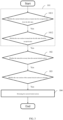
- FIG. 5 is a flow chart of Embodiment V of a method for route release in CI, as provided in detailed description of the present disclosure. As shown in FIG. 5 , after the rear section of the current locked section is released, the current locked section can be immediately provided to other trains for use, thereby improving running efficiency.
- step S103 particularly includes:
- the current locked section can be immediately provided for other trains for use, and a route can be prepared for following trains as soon as possible, thereby improving running efficiency.
- a specific embodiment of the present disclosure further provides a computer storage medium including a computer executing instruction.
- the computer executing instruction is processed via a data processing device, the data processing device executes steps of:
- a specific embodiment of the present disclosure further provides a computer storage medium including a computer executing instruction.
- the data processing device executes steps of:
- a specific embodiment of the present disclosure further provides a computer storage medium including a computer executing instruction.
- the data processing device executes steps of:
- a specific embodiment of the present disclosure further provides a computer storage medium including a computer executing instruction.
- the data processing device executes steps of:
- a specific embodiment of the present disclosure further provides a computer storage medium including a computer executing instruction.
- the data processing device executes steps of:
- FIG. 6 is a structural schematic diagram of Embodiment I of an apparatus for route release in CI, as provided in detailed description of the present disclosure. As shown in FIG. 6 , the apparatus can be applied to the methods shown in FIG. 1 to FIG. 5 , and if a train normally drives into a current locked section and drives away from the current locked section, the current locked section is released.
- the apparatus for route release in CI includes: a first judging unit 1, a second judging unit 2, a third judging unit 3 and a releasing unit 4, wherein the first judging unit 1 is used for judging whether the train normally drives into the current locked section; the second judging unit 2 is used for judging whether the train drives away from the current locked section when a judging result of the first judging unit 1 is yes; the third judging unit 3 is used for judging whether a rear section of the current locked section is released when a judging result of the second judging unit 2 is yes; and the releasing unit 4 is used for releasing the current locked section when a judging result of the third judging unit 3 is yes.
- the current locked section can be released, thereby implementing automatic release of the locked section, preventing misjudgment caused by abnormality of track circuits and maximizing running efficiency when ensuring driving safety.
- FIG. 7 is a structural schematic diagram of Embodiment II of an apparatus for route release in CI, as provided in detailed description of the present disclosure. As shown in FIG. 7 , if the train does not normally drive into the current locked section or the train does not normally drive away from the current locked section, the current locked section is kept in a locked state.
- the apparatus for route release in CI further includes: a keeping unit 5, wherein the keeping unit 5 is used for keeping the current locked section in the locked state when the judging result of at least one of the first judging unit 1, the second judging unit 2 and the third judging unit 3 is no.
- the current locked section can be released and other trains are allowed to use the released section.
- FIG. 8 a structural schematic diagram of Embodiment III of an apparatus for route release in CI, as provided in detailed description of the present disclosure. As shown in FIG. 8 , only when a state of the rear section is turned into an idle state from an occupied state and a state of the current locked section is turned into an occupied state from an idle state, it is determined that the train normally drives into the current locked section.
- the first judging unit 1 particularly includes: a first judging module 11, a second judging module 12 and a determining module 13, wherein the first judging module 11 is used for judging whether the current locked section is turned into the occupied state from the idle state; the second judging module 12 is used for judging whether the rear section is turned into the idle state from the occupied state when a judging result of the first judging module is yes; and the determining module 13 is used for determining that the train normally drives into the current locked section when a judging result of the second judging module 12 is yes.
- FIG. 9 is a structural schematic diagram of Embodiment IV of an apparatus for route release in CI, as provided in detailed description of the present disclosure. As shown in FIG. 9 , only when a state of a front section is turned into an occupied state from an idle state and the state of the current locked section is turned into the idle state from the occupied state, it is determined that the train normally drives away from the current locked section.
- the second judging unit 2 particularly includes: a first judging module 21, a second judging module 22 and a determining module 23, wherein the first judging module 21 is used for judging whether the front section is turned into the occupied state from the idle state; the second judging module 22 is used for judging whether the current locked section is turned into the idle state from the occupied state when a judging result of the first judging module 21 is yes; and the determining module 23 is used for determining that the train normally drives away from the current locked section when a judging result of the second judging module 22 is yes.
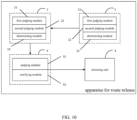
- FIG. 10 is a structural schematic diagram of Embodiment V of an apparatus for route release in CI, as provided in detailed description of the present disclosure. As shown in FIG. 10 , after the rear section of the current locked section is released, the current locked section can be immediately provided to other trains for use, thereby improving running efficiency.
- the third judging unit 3 particularly includes: a judging module 31 and a notifying module 32, wherein the judging module 31 is used for judging whether the rear section is released; and the notifying module 32 is used for notifying the releasing unit to release the current locked section if a judging result of the judging module is yes.
- the current locked section can be immediately provided to other trains for use and a route can be prepared for the following trains as soon as possible, thereby improving running efficiency.
- the specific embodiments of the present disclosure provide the method and apparatus for route release in CI, and the computer storage medium.
- Whether the train normally passes through the locked section is detected and determined in a three-point section check mode, i.e., only when the train normally drives into the current locked section and normally drives away from the current locked section, the current locked section can be allowed to be released, thereby avoiding misjudgment caused when the track circuits are abnormal; and whether the train normally passes through the locked section can be accurately determined by the state of the front section and the states of the rear section and the current section (the current locked section), thereby maximizing running efficiency when ensuring driving safety.
- the above-mentioned embodiments of the present disclosure can be implemented in various hardware, software coding or combination thereof.
- the embodiments of the present disclosure also can be program codes for executing the above-mentioned method in a Digital Signal Processor (DSP).
- DSP Digital Signal Processor
- the present disclosure also can relate to various functions executed by a computer processor, the DSP, a microprocessor or a Field Programmable Gate Array (FPGA).
- the above-mentioned processors can be configured according to the present disclosure to execute specific tasks, and complete by executing machine readable software codes or firmware codes defining the specific method disclosed by the present disclosure.
- the software codes or the firmware codes can be developed into different program languages or different formats or forms.
- the software codes or the firmware codes also can be different target platform compiled software codes.
Landscapes
- Engineering & Computer Science (AREA)
- Mechanical Engineering (AREA)
- Train Traffic Observation, Control, And Security (AREA)
- Electric Propulsion And Braking For Vehicles (AREA)
Claims (3)
- Verfahren zum Freigeben einer Fahrstraße im Computerstellwerk, umfassend:Beurteilen (101) in einem ersten Schritt, ob ein Zug normalerweise in einen aktuell gesperrten Abschnitt einfährt;wenn das Ergebnis des ersten Schritts ja ist, Beurteilen (102) in einem zweiten Schritt, ob der Zug aus dem aktuell gesperrten Abschnitt herausfährt;wenn ein Ergebnis des zweiten Schritts ja ist, Beurteilen (103) in einem dritten Schritt, ob ein hinterer Abschnitt des aktuell gesperrten Abschnitts freigegeben ist; undwenn das Ergebnis des dritten Schritts ja ist, Freigeben (104) in einem vierten Schritt des aktuell gesperrten Abschnitts,wobei, wenn eines der Beurteilungsergebnisse des ersten, des zweiten und des dritten Schritts nein sind, Halten (105) des aktuell gesperrten Abschnitts in einem gesperrten Zustand,wobei der Schritt des Beurteilens (101), ob der Zug normalerweise in den aktuell gesperrten Abschnitt fährt, umfasst:Beurteilen (1011) in einem fünften Schritt, ob der aktuell gesperrte Abschnitt von einem Leerzustand in einen Belegt-Zustand überführt wird;wenn ein Beurteilungsergebnis des fünften Schritts ja ist, Beurteilen (1012) in einem sechsten Schritt, ob der hintere Abschnitt von einem Belegt-Zustand in einen Leerzustand umgeschaltet wird; undwenn das Ergebnis des sechsten Schritts ja lautet, Bestimmen, dass der Zug normalerweise in den aktuell gesperrten Abschnitt einfährt,wobei der Schritt des Beurteilens (102), ob der Zug von dem aktuellen gesperrten Abschnitt wegfährt, umfasst:Beurteilen (1021) in einem siebten Schritt, ob ein vorderer Abschnitt aus dem Leerzustand in den Belegt-Zustand gewechselt ist;wenn ein Beurteilungsergebnis des siebten Schritts ja ist, Beurteilen (1022) in einem achten Schritt, ob der aktuell gesperrte Abschnitt aus dem Belegt-Zustand in den Leerzustand übergeht; undwenn das Ergebnis des achten Schritts ja lautet, Bestimmen, dass der Zug normalerweise von dem aktuell gesperrten Abschnitt wegfährt.
- Computerspeichermedium mit einem Computerausführungsbefehl, wobei, wenn der Computerausführungsbefehl über eine Datenverarbeitungsvorrichtung verarbeitet wird, die Datenverarbeitungsvorrichtung das Verfahren nach Anspruch 1 ausführt.
- Vorrichtung zum Freigeben einer Fahrstraße im Computerstellwerk, umfassend:eine erste Beurteilungseinheit (1), die so konfiguriert ist, dass sie beurteilt, ob ein Zug normalerweise in einen aktuell gesperrten Abschnitt einfährt;eine zweite Beurteilungseinheit (2), die so konfiguriert ist, dass sie beurteilt, ob der Zug von dem aktuell gesperrten Abschnitt wegfährt, wenn ein Beurteilungsergebnis der ersten Beurteilungseinheit ja ist;eine dritte Beurteilungseinheit (3), die so konfiguriert ist, dass sie beurteilt, ob ein hinterer Abschnitt des aktuell gesperrten Abschnitts freigegeben ist, wenn ein Beurteilungsergebnis der zweiten Beurteilungseinheit ja ist;eine Freigabeeinheit (4), die so konfiguriert ist, dass sie den aktuell gesperrten Abschnitt freigibt, wenn ein Beurteilungsergebnis der dritten Beurteilungseinheit positiv ist, undeine Halteeinheit (5), die so konfiguriert ist, dass sie den aktuell gesperrten Abschnitt in einem gesperrten Zustand hält, wenn das Beurteilungsergebnis der ersten Beurteilungseinheit (1) oder/und der zweiten Beurteilungseinheit (2) oder/und das Beurteilungsergebnis der dritten Beurteilungseinheit (3) nein ist,wobei die erste Beurteilungseinheit (1) umfasst:ein erstes Beurteilungsmodul (11), das so konfiguriert ist, dass es beurteilt, ob der aktuell gesperrte Abschnitt von einem Leerzustand in einen Belegt-Zustand übergeht;ein zweites Beurteilungsmodul (12), das so konfiguriert ist, dass es beurteilt, ob der hintere Abschnitt vom Belegt-Zustand in den Leerzustand übergeht, wenn ein Beurteilungsergebnis des ersten Beurteilungsmoduls (11) "ja" ist; undein Bestimmungsmodul (13), das so konfiguriert ist, dass es bestimmt, dass der Zug normalerweise in den aktuell gesperrten Abschnitt einfährt, wenn ein Beurteilungsergebnis des zweiten Beurteilungsmoduls (12) ja ist,wobei die zweite Beurteilungseinheit (2) umfasst:ein erstes Beurteilungsmodul (21), das so konfiguriert ist, dass es beurteilt, ob ein vorderer Abschnitt vom Leerzustand in den Belegt-Zustand übergeht;ein zweites Beurteilungsmodul (22), das so konfiguriert ist, dass es beurteilt, ob der aktuell gesperrte Abschnitt vom Belegt-Zustand in den Leerzustand übergeht, wenn ein Beurteilungsergebnis des ersten Beurteilungsmoduls (21) ja ist; undein Bestimmungsmodul (23), das so konfiguriert ist, dass es bestimmt, dass der Zug normalerweise von dem aktuell gesperrten Abschnitt wegfährt, wenn ein Beurteilungsergebnis des zweiten Beurteilungsmoduls (22) ja ist,wobei die dritte Beurteilungseinheit (3) umfasst:
ein Meldemodul (32), das so konfiguriert ist, um der Freigabeeinheit (4) mitzuteilen, dass der aktuell gesperrte Abschnitt freigegeben werden soll, wenn ein Beurteilungsergebnis des Beurteilungsmoduls ja lautet.
Priority Applications (1)
| Application Number | Priority Date | Filing Date | Title |
|---|---|---|---|
| RS20240448A RS65438B1 (sr) | 2017-11-13 | 2018-05-07 | Postupak i aparat za oslobađanje rute u računarskom preklapanju i računarski medijum za skladištenje |
Applications Claiming Priority (2)
| Application Number | Priority Date | Filing Date | Title |
|---|---|---|---|
| CN201711113006.XA CN108082216B (zh) | 2017-11-13 | 2017-11-13 | 计算机联锁中进路解锁的方法及装置、计算机存储介质 |
| PCT/CN2018/085830 WO2019091060A1 (zh) | 2017-11-13 | 2018-05-07 | 计算机联锁中进路解锁的方法及装置、计算机存储介质 |
Publications (4)
| Publication Number | Publication Date |
|---|---|
| EP3594085A1 EP3594085A1 (de) | 2020-01-15 |
| EP3594085A4 EP3594085A4 (de) | 2020-07-01 |
| EP3594085C0 EP3594085C0 (de) | 2024-01-17 |
| EP3594085B1 true EP3594085B1 (de) | 2024-01-17 |
Family
ID=62172123
Family Applications (1)
| Application Number | Title | Priority Date | Filing Date |
|---|---|---|---|
| EP18877161.2A Active EP3594085B1 (de) | 2017-11-13 | 2018-05-07 | Verfahren und vorrichtung zum auflösen der fahrstrasse bei computerstellwerk und computerspeichermedium |
Country Status (6)
| Country | Link |
|---|---|
| EP (1) | EP3594085B1 (de) |
| CN (1) | CN108082216B (de) |
| EA (1) | EA039657B1 (de) |
| HU (1) | HUE065132T2 (de) |
| RS (1) | RS65438B1 (de) |
| WO (1) | WO2019091060A1 (de) |
Families Citing this family (11)
| Publication number | Priority date | Publication date | Assignee | Title |
|---|---|---|---|---|
| CN111434558B (zh) * | 2019-01-15 | 2022-06-24 | 宝山钢铁股份有限公司 | 基于机车作业指令的机车短进路开放控制方法 |
| CN110641524B (zh) * | 2019-10-31 | 2021-11-02 | 中铁二院工程集团有限责任公司 | 一种基于联锁产生的移动授权对列车进行连续控制的方法 |
| CN111105328A (zh) * | 2019-12-24 | 2020-05-05 | 北京智联友道科技有限公司 | 联锁仿真系统行车模拟的实现方法、存储介质和电子设备 |
| CN111469889B (zh) * | 2020-04-28 | 2022-01-28 | 合肥工大高科信息科技股份有限公司 | 一种计算机联锁轨道停电故障防护方法、装置及系统 |
| CN114802259B (zh) * | 2021-01-19 | 2025-08-15 | 北京隐空科技有限公司 | 基于柔性轨道进路式点阵结构的无人驾驶控制系统及方法 |
| CN113104062B (zh) * | 2021-05-24 | 2022-07-05 | 卡斯柯信号有限公司 | 一种联锁系统控制方法 |
| CN115892129B (zh) * | 2021-08-06 | 2025-10-17 | 比亚迪股份有限公司 | 进路区段解锁的方法、联锁系统和计算机可读存储介质 |
| CN114137940B (zh) * | 2021-11-29 | 2024-03-12 | 卡斯柯信号有限公司 | 根据区间运行方向自动开关区间占用逻辑检查的方法 |
| CN116252826B (zh) * | 2021-12-10 | 2026-02-10 | 比亚迪股份有限公司 | 进路区段状态的跳转判定方法、装置以及存储介质 |
| CN114275009B (zh) * | 2021-12-22 | 2023-09-05 | 卡斯柯信号有限公司 | 基于全电子联锁的防止进路错误解锁方法、设备及介质 |
| CN119636850B (zh) * | 2024-12-31 | 2025-09-30 | 卡斯柯信号有限公司 | 一种多数据源的进路状态一致性比较方法及系统 |
Family Cites Families (7)
| Publication number | Priority date | Publication date | Assignee | Title |
|---|---|---|---|---|
| CN102285364B (zh) * | 2011-05-05 | 2013-10-23 | 西安理工大学 | 一种基于列车优先级的分散式列车并发调度方法 |
| DE102012217817A1 (de) * | 2012-09-28 | 2014-04-03 | Siemens Aktiengesellschaft | Steuerung eines Schienenfahrzeugs |
| CN104512439B (zh) * | 2013-09-27 | 2017-08-11 | 湖南中车时代通信信号有限公司 | 一种进路解锁方法及装置 |
| CN106394614A (zh) * | 2016-10-11 | 2017-02-15 | 通号万全信号设备有限公司 | 导轨电车安全型轨旁联锁控制方法及系统 |
| CN106476847B (zh) * | 2016-10-13 | 2018-10-09 | 交控科技股份有限公司 | 进路保护区段的解锁方法及装置 |
| CN106697004B (zh) * | 2016-12-19 | 2019-06-11 | 交控科技股份有限公司 | Spks开关及联锁系统、联锁系统的使用方法 |
| CN106828541B (zh) * | 2017-01-23 | 2019-01-15 | 北京交通大学 | 适合于车-车通信的列控系统车载联锁的进路防护方法 |
-
2017
- 2017-11-13 CN CN201711113006.XA patent/CN108082216B/zh active Active
-
2018
- 2018-05-07 EA EA202091189A patent/EA039657B1/ru unknown
- 2018-05-07 WO PCT/CN2018/085830 patent/WO2019091060A1/zh not_active Ceased
- 2018-05-07 RS RS20240448A patent/RS65438B1/sr unknown
- 2018-05-07 HU HUE18877161A patent/HUE065132T2/hu unknown
- 2018-05-07 EP EP18877161.2A patent/EP3594085B1/de active Active
Also Published As
| Publication number | Publication date |
|---|---|
| RS65438B1 (sr) | 2024-05-31 |
| CN108082216A (zh) | 2018-05-29 |
| EA202091189A1 (ru) | 2020-12-07 |
| CN108082216B (zh) | 2020-04-21 |
| EP3594085A4 (de) | 2020-07-01 |
| EP3594085C0 (de) | 2024-01-17 |
| HUE065132T2 (hu) | 2024-05-28 |
| EP3594085A1 (de) | 2020-01-15 |
| EA039657B1 (ru) | 2022-02-22 |
| WO2019091060A1 (zh) | 2019-05-16 |
Similar Documents
| Publication | Publication Date | Title |
|---|---|---|
| EP3594085B1 (de) | Verfahren und vorrichtung zum auflösen der fahrstrasse bei computerstellwerk und computerspeichermedium | |
| CN112874582B (zh) | 列车及其的控制方法、控制装置和车载控制设备 | |
| CN110775101B (zh) | 轨道交通信号系统全自动运行下的远程rm运行控制方法 | |
| CN110758484A (zh) | 列车自动驾驶方法、vobc、tias、区域控制器 | |
| US9971349B2 (en) | Method and device for monitoring a system of a vehicle which provides an at least partially automated driving function | |
| CN114261432B (zh) | 全自动无人驾驶远程反向运行的实现方法、设备及介质 | |
| CN107709136B (zh) | 用于为轨道车辆确定行驶授权的方法和装置 | |
| CN109153393B (zh) | 车辆控制系统 | |
| CN109278807B (zh) | 基于车车通信列控系统的列车跳停方法 | |
| CN110758494A (zh) | 一种临时限速方法、装置、电子设备及存储介质 | |
| CN113401184A (zh) | 远程限速运行控制方法、装置、电子设备及存储介质 | |
| JP4626543B2 (ja) | 自動隊列走行制御装置および自動隊列走行制御システム | |
| JP5029480B2 (ja) | 車両用通報装置 | |
| DK3036146T3 (en) | OPERATION OF A SKIN VEHICLE | |
| GB2536002A (en) | Railway Vehicle Operation | |
| CN105730456B (zh) | 动车组站台侧车门开启系统 | |
| CN107878514B (zh) | 一种列车自动驾驶ato设备故障的安全处理方法及系统 | |
| CN113060189A (zh) | 列车管理方法、装置、装置和电子设备 | |
| US11675368B2 (en) | Systems and methods for preserving route instruction information | |
| CN105848985A (zh) | 轨道车辆的控制 | |
| CN108116453A (zh) | 一种列车按信号机编号开车对标的方法 | |
| CN113815677A (zh) | 列车发车控制方法、装置、电子设备及存储介质 | |
| CN113428165A (zh) | 一种基于mdc300的矿车自动驾驶安全系统及方法 | |
| RU2729132C1 (ru) | Способ эксплуатации технического оборудования сортировочной горки и система управления такой горкой | |
| CN118514737A (zh) | 一种应用于列车运行的地面控制方法和地面控制设备 |
Legal Events
| Date | Code | Title | Description |
|---|---|---|---|
| STAA | Information on the status of an ep patent application or granted ep patent |
Free format text: STATUS: THE INTERNATIONAL PUBLICATION HAS BEEN MADE |
|
| PUAI | Public reference made under article 153(3) epc to a published international application that has entered the european phase |
Free format text: ORIGINAL CODE: 0009012 |
|
| STAA | Information on the status of an ep patent application or granted ep patent |
Free format text: STATUS: REQUEST FOR EXAMINATION WAS MADE |
|
| 17P | Request for examination filed |
Effective date: 20191007 |
|
| AK | Designated contracting states |
Kind code of ref document: A1 Designated state(s): AL AT BE BG CH CY CZ DE DK EE ES FI FR GB GR HR HU IE IS IT LI LT LU LV MC MK MT NL NO PL PT RO RS SE SI SK SM TR |
|
| AX | Request for extension of the european patent |
Extension state: BA ME |
|
| A4 | Supplementary search report drawn up and despatched |
Effective date: 20200529 |
|
| RIC1 | Information provided on ipc code assigned before grant |
Ipc: B61L 19/06 20060101ALN20200525BHEP Ipc: B61L 23/14 20060101ALI20200525BHEP Ipc: B61L 27/00 20060101ALI20200525BHEP Ipc: B61L 23/30 20060101ALI20200525BHEP Ipc: B61L 23/00 20060101AFI20200525BHEP |
|
| DAV | Request for validation of the european patent (deleted) | ||
| DAX | Request for extension of the european patent (deleted) | ||
| STAA | Information on the status of an ep patent application or granted ep patent |
Free format text: STATUS: EXAMINATION IS IN PROGRESS |
|
| 17Q | First examination report despatched |
Effective date: 20210531 |
|
| REG | Reference to a national code |
Ref country code: DE Ref legal event code: R079 Ref document number: 602018064357 Country of ref document: DE Free format text: PREVIOUS MAIN CLASS: B61L0023000000 Ipc: B61L0023300000 Ref country code: DE Ref legal event code: R079 Free format text: PREVIOUS MAIN CLASS: B61L0023000000 Ipc: B61L0023300000 |
|
| GRAP | Despatch of communication of intention to grant a patent |
Free format text: ORIGINAL CODE: EPIDOSNIGR1 |
|
| STAA | Information on the status of an ep patent application or granted ep patent |
Free format text: STATUS: GRANT OF PATENT IS INTENDED |
|
| RIC1 | Information provided on ipc code assigned before grant |
Ipc: B61L 19/06 20060101ALN20230705BHEP Ipc: B61L 27/40 20220101ALI20230705BHEP Ipc: B61L 27/20 20220101ALI20230705BHEP Ipc: B61L 23/14 20060101ALI20230705BHEP Ipc: B61L 23/30 20060101AFI20230705BHEP |
|
| RIC1 | Information provided on ipc code assigned before grant |
Ipc: B61L 19/06 20060101ALN20230707BHEP Ipc: B61L 27/40 20220101ALI20230707BHEP Ipc: B61L 27/20 20220101ALI20230707BHEP Ipc: B61L 23/14 20060101ALI20230707BHEP Ipc: B61L 23/30 20060101AFI20230707BHEP |
|
| INTG | Intention to grant announced |
Effective date: 20230804 |
|
| GRAS | Grant fee paid |
Free format text: ORIGINAL CODE: EPIDOSNIGR3 |
|
| GRAA | (expected) grant |
Free format text: ORIGINAL CODE: 0009210 |
|
| STAA | Information on the status of an ep patent application or granted ep patent |
Free format text: STATUS: THE PATENT HAS BEEN GRANTED |
|
| AK | Designated contracting states |
Kind code of ref document: B1 Designated state(s): AL AT BE BG CH CY CZ DE DK EE ES FI FR GB GR HR HU IE IS IT LI LT LU LV MC MK MT NL NO PL PT RO RS SE SI SK SM TR |
|
| REG | Reference to a national code |
Ref country code: GB Ref legal event code: FG4D |
|
| REG | Reference to a national code |
Ref country code: CH Ref legal event code: EP |
|
| REG | Reference to a national code |
Ref country code: DE Ref legal event code: R096 Ref document number: 602018064357 Country of ref document: DE |
|
| REG | Reference to a national code |
Ref country code: IE Ref legal event code: FG4D |
|
| U01 | Request for unitary effect filed |
Effective date: 20240201 |
|
| U07 | Unitary effect registered |
Designated state(s): AT BE BG DE DK EE FI FR IT LT LU LV MT NL PT SE SI Effective date: 20240209 |
|
| REG | Reference to a national code |
Ref country code: HU Ref legal event code: AG4A Ref document number: E065132 Country of ref document: HU |
|
| U20 | Renewal fee for the european patent with unitary effect paid |
Year of fee payment: 7 Effective date: 20240506 |
|
| PG25 | Lapsed in a contracting state [announced via postgrant information from national office to epo] |
Ref country code: IS Free format text: LAPSE BECAUSE OF FAILURE TO SUBMIT A TRANSLATION OF THE DESCRIPTION OR TO PAY THE FEE WITHIN THE PRESCRIBED TIME-LIMIT Effective date: 20240517 |
|
| PG25 | Lapsed in a contracting state [announced via postgrant information from national office to epo] |
Ref country code: GR Free format text: LAPSE BECAUSE OF FAILURE TO SUBMIT A TRANSLATION OF THE DESCRIPTION OR TO PAY THE FEE WITHIN THE PRESCRIBED TIME-LIMIT Effective date: 20240418 |
|
| PG25 | Lapsed in a contracting state [announced via postgrant information from national office to epo] |
Ref country code: HR Free format text: LAPSE BECAUSE OF FAILURE TO SUBMIT A TRANSLATION OF THE DESCRIPTION OR TO PAY THE FEE WITHIN THE PRESCRIBED TIME-LIMIT Effective date: 20240117 |
|
| PG25 | Lapsed in a contracting state [announced via postgrant information from national office to epo] |
Ref country code: ES Free format text: LAPSE BECAUSE OF FAILURE TO SUBMIT A TRANSLATION OF THE DESCRIPTION OR TO PAY THE FEE WITHIN THE PRESCRIBED TIME-LIMIT Effective date: 20240117 |
|
| PG25 | Lapsed in a contracting state [announced via postgrant information from national office to epo] |
Ref country code: NO Free format text: LAPSE BECAUSE OF FAILURE TO SUBMIT A TRANSLATION OF THE DESCRIPTION OR TO PAY THE FEE WITHIN THE PRESCRIBED TIME-LIMIT Effective date: 20240417 Ref country code: IS Free format text: LAPSE BECAUSE OF FAILURE TO SUBMIT A TRANSLATION OF THE DESCRIPTION OR TO PAY THE FEE WITHIN THE PRESCRIBED TIME-LIMIT Effective date: 20240517 Ref country code: HR Free format text: LAPSE BECAUSE OF FAILURE TO SUBMIT A TRANSLATION OF THE DESCRIPTION OR TO PAY THE FEE WITHIN THE PRESCRIBED TIME-LIMIT Effective date: 20240117 Ref country code: GR Free format text: LAPSE BECAUSE OF FAILURE TO SUBMIT A TRANSLATION OF THE DESCRIPTION OR TO PAY THE FEE WITHIN THE PRESCRIBED TIME-LIMIT Effective date: 20240418 Ref country code: ES Free format text: LAPSE BECAUSE OF FAILURE TO SUBMIT A TRANSLATION OF THE DESCRIPTION OR TO PAY THE FEE WITHIN THE PRESCRIBED TIME-LIMIT Effective date: 20240117 |
|
| PG25 | Lapsed in a contracting state [announced via postgrant information from national office to epo] |
Ref country code: PL Free format text: LAPSE BECAUSE OF FAILURE TO SUBMIT A TRANSLATION OF THE DESCRIPTION OR TO PAY THE FEE WITHIN THE PRESCRIBED TIME-LIMIT Effective date: 20240117 |
|
| PG25 | Lapsed in a contracting state [announced via postgrant information from national office to epo] |
Ref country code: PL Free format text: LAPSE BECAUSE OF FAILURE TO SUBMIT A TRANSLATION OF THE DESCRIPTION OR TO PAY THE FEE WITHIN THE PRESCRIBED TIME-LIMIT Effective date: 20240117 |
|
| PG25 | Lapsed in a contracting state [announced via postgrant information from national office to epo] |
Ref country code: SM Free format text: LAPSE BECAUSE OF FAILURE TO SUBMIT A TRANSLATION OF THE DESCRIPTION OR TO PAY THE FEE WITHIN THE PRESCRIBED TIME-LIMIT Effective date: 20240117 |
|
| REG | Reference to a national code |
Ref country code: DE Ref legal event code: R097 Ref document number: 602018064357 Country of ref document: DE |
|
| PG25 | Lapsed in a contracting state [announced via postgrant information from national office to epo] |
Ref country code: CZ Free format text: LAPSE BECAUSE OF FAILURE TO SUBMIT A TRANSLATION OF THE DESCRIPTION OR TO PAY THE FEE WITHIN THE PRESCRIBED TIME-LIMIT Effective date: 20240117 |
|
| PG25 | Lapsed in a contracting state [announced via postgrant information from national office to epo] |
Ref country code: SK Free format text: LAPSE BECAUSE OF FAILURE TO SUBMIT A TRANSLATION OF THE DESCRIPTION OR TO PAY THE FEE WITHIN THE PRESCRIBED TIME-LIMIT Effective date: 20240117 |
|
| PG25 | Lapsed in a contracting state [announced via postgrant information from national office to epo] |
Ref country code: SM Free format text: LAPSE BECAUSE OF FAILURE TO SUBMIT A TRANSLATION OF THE DESCRIPTION OR TO PAY THE FEE WITHIN THE PRESCRIBED TIME-LIMIT Effective date: 20240117 Ref country code: SK Free format text: LAPSE BECAUSE OF FAILURE TO SUBMIT A TRANSLATION OF THE DESCRIPTION OR TO PAY THE FEE WITHIN THE PRESCRIBED TIME-LIMIT Effective date: 20240117 Ref country code: RO Free format text: LAPSE BECAUSE OF FAILURE TO SUBMIT A TRANSLATION OF THE DESCRIPTION OR TO PAY THE FEE WITHIN THE PRESCRIBED TIME-LIMIT Effective date: 20240117 Ref country code: CZ Free format text: LAPSE BECAUSE OF FAILURE TO SUBMIT A TRANSLATION OF THE DESCRIPTION OR TO PAY THE FEE WITHIN THE PRESCRIBED TIME-LIMIT Effective date: 20240117 |
|
| PLBE | No opposition filed within time limit |
Free format text: ORIGINAL CODE: 0009261 |
|
| STAA | Information on the status of an ep patent application or granted ep patent |
Free format text: STATUS: NO OPPOSITION FILED WITHIN TIME LIMIT |
|
| 26N | No opposition filed |
Effective date: 20241018 |
|
| REG | Reference to a national code |
Ref country code: CH Ref legal event code: PL |
|
| PG25 | Lapsed in a contracting state [announced via postgrant information from national office to epo] |
Ref country code: MC Free format text: LAPSE BECAUSE OF FAILURE TO SUBMIT A TRANSLATION OF THE DESCRIPTION OR TO PAY THE FEE WITHIN THE PRESCRIBED TIME-LIMIT Effective date: 20240117 |
|
| GBPC | Gb: european patent ceased through non-payment of renewal fee |
Effective date: 20240507 |
|
| PG25 | Lapsed in a contracting state [announced via postgrant information from national office to epo] |
Ref country code: MC Free format text: LAPSE BECAUSE OF FAILURE TO SUBMIT A TRANSLATION OF THE DESCRIPTION OR TO PAY THE FEE WITHIN THE PRESCRIBED TIME-LIMIT Effective date: 20240117 Ref country code: CH Free format text: LAPSE BECAUSE OF NON-PAYMENT OF DUE FEES Effective date: 20240531 |
|
| PG25 | Lapsed in a contracting state [announced via postgrant information from national office to epo] |
Ref country code: IE Free format text: LAPSE BECAUSE OF NON-PAYMENT OF DUE FEES Effective date: 20240507 |
|
| PG25 | Lapsed in a contracting state [announced via postgrant information from national office to epo] |
Ref country code: GB Free format text: LAPSE BECAUSE OF NON-PAYMENT OF DUE FEES Effective date: 20240507 |
|
| U20 | Renewal fee for the european patent with unitary effect paid |
Year of fee payment: 8 Effective date: 20250403 |
|
| PGFP | Annual fee paid to national office [announced via postgrant information from national office to epo] |
Ref country code: RS Payment date: 20250408 Year of fee payment: 8 Ref country code: HU Payment date: 20250526 Year of fee payment: 8 |
|
| PG25 | Lapsed in a contracting state [announced via postgrant information from national office to epo] |
Ref country code: CY Free format text: LAPSE BECAUSE OF FAILURE TO SUBMIT A TRANSLATION OF THE DESCRIPTION OR TO PAY THE FEE WITHIN THE PRESCRIBED TIME-LIMIT; INVALID AB INITIO Effective date: 20180507 |