EP3593118B1 - Atr spectrometer and method for analysing the chemical composition of a sample - Google Patents
Atr spectrometer and method for analysing the chemical composition of a sample Download PDFInfo
- Publication number
- EP3593118B1 EP3593118B1 EP18712092.8A EP18712092A EP3593118B1 EP 3593118 B1 EP3593118 B1 EP 3593118B1 EP 18712092 A EP18712092 A EP 18712092A EP 3593118 B1 EP3593118 B1 EP 3593118B1
- Authority
- EP
- European Patent Office
- Prior art keywords
- infrared light
- light detectors
- chosen
- detectors
- atr
- Prior art date
- Legal status (The legal status is an assumption and is not a legal conclusion. Google has not performed a legal analysis and makes no representation as to the accuracy of the status listed.)
- Active
Links
Images

Classifications
-
- G—PHYSICS
- G01—MEASURING; TESTING
- G01J—MEASUREMENT OF INTENSITY, VELOCITY, SPECTRAL CONTENT, POLARISATION, PHASE OR PULSE CHARACTERISTICS OF INFRARED, VISIBLE OR ULTRAVIOLET LIGHT; COLORIMETRY; RADIATION PYROMETRY
- G01J3/00—Spectrometry; Spectrophotometry; Monochromators; Measuring colours
- G01J3/28—Investigating the spectrum
- G01J3/2803—Investigating the spectrum using photoelectric array detector
-
- G—PHYSICS
- G01—MEASURING; TESTING
- G01J—MEASUREMENT OF INTENSITY, VELOCITY, SPECTRAL CONTENT, POLARISATION, PHASE OR PULSE CHARACTERISTICS OF INFRARED, VISIBLE OR ULTRAVIOLET LIGHT; COLORIMETRY; RADIATION PYROMETRY
- G01J3/00—Spectrometry; Spectrophotometry; Monochromators; Measuring colours
- G01J3/28—Investigating the spectrum
- G01J3/30—Measuring the intensity of spectral lines directly on the spectrum itself
- G01J3/36—Investigating two or more bands of a spectrum by separate detectors
-
- G—PHYSICS
- G01—MEASURING; TESTING
- G01J—MEASUREMENT OF INTENSITY, VELOCITY, SPECTRAL CONTENT, POLARISATION, PHASE OR PULSE CHARACTERISTICS OF INFRARED, VISIBLE OR ULTRAVIOLET LIGHT; COLORIMETRY; RADIATION PYROMETRY
- G01J3/00—Spectrometry; Spectrophotometry; Monochromators; Measuring colours
- G01J3/28—Investigating the spectrum
- G01J3/42—Absorption spectrometry; Double beam spectrometry; Flicker spectrometry; Reflection spectrometry
-
- G—PHYSICS
- G01—MEASURING; TESTING
- G01N—INVESTIGATING OR ANALYSING MATERIALS BY DETERMINING THEIR CHEMICAL OR PHYSICAL PROPERTIES
- G01N21/00—Investigating or analysing materials by the use of optical means, i.e. using sub-millimetre waves, infrared, visible or ultraviolet light
- G01N21/17—Systems in which incident light is modified in accordance with the properties of the material investigated
- G01N21/25—Colour; Spectral properties, i.e. comparison of effect of material on the light at two or more different wavelengths or wavelength bands
- G01N21/27—Colour; Spectral properties, i.e. comparison of effect of material on the light at two or more different wavelengths or wavelength bands using photo-electric detection ; circuits for computing concentration
- G01N21/274—Calibration, base line adjustment, drift correction
-
- G—PHYSICS
- G01—MEASURING; TESTING
- G01N—INVESTIGATING OR ANALYSING MATERIALS BY DETERMINING THEIR CHEMICAL OR PHYSICAL PROPERTIES
- G01N21/00—Investigating or analysing materials by the use of optical means, i.e. using sub-millimetre waves, infrared, visible or ultraviolet light
- G01N21/17—Systems in which incident light is modified in accordance with the properties of the material investigated
- G01N21/25—Colour; Spectral properties, i.e. comparison of effect of material on the light at two or more different wavelengths or wavelength bands
- G01N21/31—Investigating relative effect of material at wavelengths characteristic of specific elements or molecules, e.g. atomic absorption spectrometry
- G01N21/35—Investigating relative effect of material at wavelengths characteristic of specific elements or molecules, e.g. atomic absorption spectrometry using infrared light
-
- G—PHYSICS
- G01—MEASURING; TESTING
- G01N—INVESTIGATING OR ANALYSING MATERIALS BY DETERMINING THEIR CHEMICAL OR PHYSICAL PROPERTIES
- G01N21/00—Investigating or analysing materials by the use of optical means, i.e. using sub-millimetre waves, infrared, visible or ultraviolet light
- G01N21/17—Systems in which incident light is modified in accordance with the properties of the material investigated
- G01N21/55—Specular reflectivity
- G01N21/552—Attenuated total reflection
-
- G—PHYSICS
- G01—MEASURING; TESTING
- G01J—MEASUREMENT OF INTENSITY, VELOCITY, SPECTRAL CONTENT, POLARISATION, PHASE OR PULSE CHARACTERISTICS OF INFRARED, VISIBLE OR ULTRAVIOLET LIGHT; COLORIMETRY; RADIATION PYROMETRY
- G01J3/00—Spectrometry; Spectrophotometry; Monochromators; Measuring colours
- G01J3/28—Investigating the spectrum
- G01J2003/2866—Markers; Calibrating of scan
- G01J2003/2869—Background correcting
-
- G—PHYSICS
- G01—MEASURING; TESTING
- G01J—MEASUREMENT OF INTENSITY, VELOCITY, SPECTRAL CONTENT, POLARISATION, PHASE OR PULSE CHARACTERISTICS OF INFRARED, VISIBLE OR ULTRAVIOLET LIGHT; COLORIMETRY; RADIATION PYROMETRY
- G01J3/00—Spectrometry; Spectrophotometry; Monochromators; Measuring colours
- G01J3/02—Details
- G01J3/0205—Optical elements not provided otherwise, e.g. optical manifolds, diffusers, windows
-
- G—PHYSICS
- G01—MEASURING; TESTING
- G01N—INVESTIGATING OR ANALYSING MATERIALS BY DETERMINING THEIR CHEMICAL OR PHYSICAL PROPERTIES
- G01N21/00—Investigating or analysing materials by the use of optical means, i.e. using sub-millimetre waves, infrared, visible or ultraviolet light
- G01N21/17—Systems in which incident light is modified in accordance with the properties of the material investigated
- G01N21/25—Colour; Spectral properties, i.e. comparison of effect of material on the light at two or more different wavelengths or wavelength bands
- G01N21/31—Investigating relative effect of material at wavelengths characteristic of specific elements or molecules, e.g. atomic absorption spectrometry
- G01N21/35—Investigating relative effect of material at wavelengths characteristic of specific elements or molecules, e.g. atomic absorption spectrometry using infrared light
- G01N21/3563—Investigating relative effect of material at wavelengths characteristic of specific elements or molecules, e.g. atomic absorption spectrometry using infrared light for analysing solids; Preparation of samples therefor
-
- G—PHYSICS
- G01—MEASURING; TESTING
- G01N—INVESTIGATING OR ANALYSING MATERIALS BY DETERMINING THEIR CHEMICAL OR PHYSICAL PROPERTIES
- G01N21/00—Investigating or analysing materials by the use of optical means, i.e. using sub-millimetre waves, infrared, visible or ultraviolet light
- G01N21/17—Systems in which incident light is modified in accordance with the properties of the material investigated
- G01N21/25—Colour; Spectral properties, i.e. comparison of effect of material on the light at two or more different wavelengths or wavelength bands
- G01N21/31—Investigating relative effect of material at wavelengths characteristic of specific elements or molecules, e.g. atomic absorption spectrometry
- G01N21/35—Investigating relative effect of material at wavelengths characteristic of specific elements or molecules, e.g. atomic absorption spectrometry using infrared light
- G01N21/3577—Investigating relative effect of material at wavelengths characteristic of specific elements or molecules, e.g. atomic absorption spectrometry using infrared light for analysing liquids, e.g. polluted water
Definitions
- the invention relates to an ATR spectrometer for analysing the chemical composition of a sample and a method for analysing the chemical composition of a sample by means of the ATR spectrometer.
- a chemical composition of a sample can be analysed by means of infrared spectroscopy.
- the infrared spectroscopy can be performed by means of an extinction spectrometer in which the sample is irradiated by broadband infrared light emitted by an infrared light source and an extinction spectrum of the sample is measured after the infrared light has passed through the sample.
- the infrared spectroscopy can be performed by means of an ATR spectrometer, in which an evanescent wave of the infrared light generated in the sample that is in contact with an ATR crystal of the ATR spectrometer interacts with the sample and an ATR spectrum is measured after the interaction.
- Both the extinction spectrum and the ATR spectrum comprise a wavelength dependent measurement of the extinction of the sample, i.e. a measurement of the attenuation of the light after interaction with the sample.
- the ATR spectrometer is advantageous in comparison to the extinction spectrometer if the sample contains water, since the peak related to water is less prominent in the ATR spectrum than in the extinction spectrum, whereby the peak related to water covers less other peaks in the ATR spectrum than in the extinction spectrum.
- the intensity of the infrared light emitted by the infrared light source is temporally fluctuating, this results also in fluctuating intensities in the ATR spectra thereby also reducing their quality.
- the ATR crystal and a linear variable filter for passing different portions of the infrared light for measuring the extinction spectra may have limited dimensions which results also in a limited space for arranging detectors of the ATR spectrometer. This limited space for the detectors results either in a low spectral resolution for the ATR spectra or the ATR spectra can only be measured in a narrow spectral range. This also reduces the quality of the
- ATR spectra discloses an ATR spectrometer comprising a plurality of detectors associated with filters to define measurement and reference channels.
- DE102013005372 A1 discloses an ATR spectrometer comprising the combination of a line sensor and an additional sensor.
- the ATR spectrometer for analysing the chemical composition of a sample comprises an ATR crystal having an entry surface being immediately arranged on an entry end of the ATR crystal and an exit surface being immediately arranged on an exit end of the ATR crystal which is arranged opposite to the entry end; at least one infrared light source being arranged on the entry surface; a line array of infrared light detectors being arranged on the exit surface; and at least one additional infrared light detector, separate from the line array,being arranged on the exit surface,wherein the at least one infrared light source is adapted to emit infrared light that enters the ATR crystal via the entry surface and is guided to the infrared light detectors in the line array and to the at least one additional infrared light detector under total internal reflection and under interaction with the sample being arranged immediately adjacent to the ATR crystal; wherein the ATR spectrometer additionally comprises a wavelength dispersive element being arranged in the path of the infrared light from the exit surface to the line array
- the infrared light is guided from the exit surface without a redirection to the infrared light detectors. This results advantageously in a simple design of the ATR spectrometer.
- the sample is arranged immediately adjacent to the ATR crystal and the chosen infrared light detector is chosen such that its corresponding detectable wavelength range is in a wavelength region where the sample has substantially no absorption. In this manner, temporal fluctuations of the intensity of the at least one infrared light source can be particularly well compensated, whereby the quality of the ATR spectra can be further increased.
- each of the single infrared detectors has a larger photoactive surface than each of the infrared light detectors of the line array. Therefore, the single infrared light detectors have a higher signal-to-noise ratio than the infrared light detectors of the line array. In case one of the single infrared light detectors is used to measure a part of the ATR spectrum, this part can be advantageously measured with a high signal-to-noise ratio. Also it is possible to quantitatively measure a certain component of the ATR spectrum. In case one of the single infrared light detectors is one of the chosen infrared light detector for the signal correction, the signal correction can be carried out with a high precision due to the high signal-to-noise ratio. In both cases, the large photoactive surface of the single infrared light detectors results in an increased quality of the ATR spectra.
- the wavelength filter being arranged in the path of the infrared light from the exit surface to the single infrared light detector is preferably a bandpass filter.
- the spectral resolution for at least one of the single infrared light detectors is higher than for all of the infrared light detectors of the line array. In case this single infrared light detector is used for measuring a part of the ATR spectrum, a peak of the ATR spectrum might be resolved that cannot be made visible by the line array due to the lower spectral resolution of the line array.
- this single infrared light detector is one of the chosen infrared light detectors for the signal correction
- the signal correction can be carried out with a higher precision than it is possible with one of the infrared light detectors of the line array due to their lower spectral resolution.
- the large high spectral resolution of the single infrared light detector results in an increased quality of the ATR spectra.
- the chosen infrared light detectors are wired with all the other infrared light detectors such that during operation of the ATR spectrometer the electrical signals output by the chosen infrared light detectors are subtracted from the electrical signals output by all the other infrared light detectors.
- the ATR spectrometer is adapted to correct the electrical signals before they are amplified and/or digitized. Also, the correction of the electrical signals is carried out by a hardware rather than by a software which results in an accelerated data processing. Due to the accelerated data processing it is possible to measure ATR spectra with a higher repetition rate. The higher repetition rate allows for more averaging of the ATR spectra which results in an increased quality for the ATR spectra.
- the correction can for example comprise a subtraction of the signal value output by the chosen infrared light detectors from the signal values of all the other infrared light detectors.
- the correction can comprise a subtraction of the inverse of the signal value output by the chosen infrared light detectors from the inverse of the signal values of all the other infrared light detectors.
- the ATR spectrometer is preferably adapted to use the electrical signal of a plurality of the chosen infrared light detectors to generate a wavelength dependent function and to correct the electrical signals of all the other infrared light detectors using the wavelength dependent function.
- the wavelength dependent function is generated by fitting the wavelength dependent function to the signal values output by the chosen infrared light detectors and the wavelength dependent function is subtracted from the signal values output by all the other infrared light detectors.
- the wavelength dependent function is generated by fitting the wavelength dependent function to the inverse of the signal values output by the chosen infrared light detectors and the wavelength dependent function is subtracted from the inverse of the signal values output by all the other infrared light detectors. It is thereby possible to correct not only variations in intensity fluctuations of the infrared light source but also spectral drifts of the infrared light source. This further increases the quality of the ATR spectra.
- At least one of the chosen infrared light detectors is one of the infrared light detectors of the line array and at least one of the chosen infrared light detectors is one of the single infrared light detectors, wherein the wavelength filter corresponding to the at least one of the chosen infrared light detectors has a transmission in a wavelength region that is outside of the spectrum that can be measured by the line array.
- the wavelength filter corresponding to the at least one of the chosen infrared light detectors has a transmission in a wavelength region that is outside of the spectrum that can be measured by the line array.
- the method for analysing the chemical composition of a sample comprises the steps: a) providing an ATR spectrometer comprising an ATR crystal having an entry surface being immediately arranged on an entry end of the ATR crystal and an exit surface being immediately arranged on an exit end of the ATR crystal which is arranged opposite to the entry end; at least one infrared light source being arranged on the entry surface; a line array of infrared light detectors being arranged on the exit surface; and at least one additional infrared light detector, separate from the line array,being arranged on the exit surface,wherein the at least one infrared light source is adapted to emit infrared light that enters the ATR crystal via the entry surface and is guided to the infrared light detectors in the line array and to the at least one additional infrared light detector under total internal reflection and under interaction with the sample being arranged immediately adjacent to the ATR crystal; wherein the ATR spectrometer additionally comprises a wavelength dispersive element being arranged in the path of the infrare
- step f) the signal value output by the chosen infrared light detectors can be subtracted from the signal values of all the other infrared light detectors.
- the inverse of the signal value output by the chosen infrared light detectors can be subtracted from the inverse of the signal values of all the other infrared light detectors. It is preferred that in step b) only one of the infrared light detectors is chosen. In this manner, fluctuations of the intensity of the infrared light emitted by the at least one infrared light source can be effectively compensated.
- a plurality of the infrared light sources is provided and that the chosen infrared light detector is impinged by the infrared light of all the infrared light sources. In this manner, it is possible to compensate the fluctuations of the intensity of the infrared light emitted by a multitude of the infrared light sources by only one of the chosen infrared light detectors.
- step b) a plurality of the infrared light detectors is chosen and that the method comprises the step: e1) generating a wavelength dependent function using the electrical signals of a multitude of the chosen infrared light detectors; wherein in step f) the electrical signals of all the other infrared light detectors are corrected by using the wavelength dependent function.
- the wavelength dependent function is generated by fitting the wavelength dependent function to the signal values output by the chosen infrared light detectors and the wavelength dependent function is subtracted from the signal values output by all the other infrared light detectors.
- the wavelength dependent function is generated by fitting the wavelength dependent function to the inverse of the signal values output by the chosen infrared light detectors and the wavelength dependent function is subtracted from the inverse of the signal values output by all the other infrared light detectors. It is therefore advantageously achieved that spectral shifts of the infrared light emitted by the infrared light sources can be compensated.
- At least one of the chosen infrared light detectors is one of the infrared light detectors of the line array and at least one of the chosen infrared light detectors is one of the single infrared light detectors, wherein the wavelength filter corresponding to the at least one of the chosen infrared light detectors has a transmission in a wavelength region that is outside of the spectrum that can be measured by the line array. It is thereby possible to correct for the effect of scattering with a particular high precision.
- step b) extinction spectra with different concentrations of the sample or of a reference sample being similar to the sample are measured, in particular by means of an FTIR spectrometer, and the wavelength regions where the sample has substantially no absorption are identified as these parts of the extinction spectra that have a smaller dependence on the concentration than its adjacent parts.
- the sample comprises ethanol and water and the ethanol concentration in the sample is supposed to be determined, it is sufficient to measure any reference sample comprising ethanol and water since different ethanol concentrations will merely result in different absolute intensities but not in spectral shifts in the extinction spectrum.
- chemometric methods For the chemometric methods, windows of the extinction spectra, for example windows in the shape of Gaussians, are selected starting from one end of the extinction spectra to the other end of the extinction spectra and these windows are subtracted in iterations of the concentration. These corrected spectra are then passed through a partial least square (PLS) regression and the root mean square of standard error (RMSE) and R 2 of the measured versus predicted concentrations are obtained. The best R 2 , i.e. being closest to 1, and the corresponding windows are chosen for the wavelength regions where the sample has substantially no absorption.
- PLS partial least square
- RMSE root mean square of standard error
- the FTIR spectrometer has a spectral resolution of at least 5 cm -1 , in particular at least 1 cm -1 . With this high spectral resolution it is particular easy to identify the wavelength region in the extinction spectrum where the sample has substantially no absorption. It is furthermore preferred that the extinction spectrum covers a spectral range from 2 ⁇ m to 20 ⁇ m.
- the FTIR spectrometer is further advantageous since it has powerful infrared light source that ensures that the infrared light penetrates the sample or the reference sample.
- step a) the inventive or one of the preferred ATR spectrometers is provided.
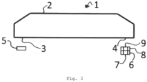
- an ATR spectrometer 1 for analysing the chemical composition of a sample comprises an ATR crystal 2, at least one infrared light source 5, a line array 6 of infrared light detectors and at least one single infrared light detector 7.
- Figures 1 and 2 show that the at least one single infrared light detector 7 and the line array 6 are arranged separately from each other with a space being arranged between the line array 6 and the single infrared light detector 7. In case a plurality of the single infrared light detectors 7 is provided, a further space can be provided between neighboured single infrared light detectors 7.
- the ATR crystal 2 has an entry surface 3 being immediately arranged on an entry end of the ATR crystal 2 and an exit surface 4 being immediately arranged on an exit end of the ATR crystal 2, wherein the exit end is arranged opposite to the entry end.
- the at least one infrared light source 5 is arranged on the entry surface 3.
- the line array 6 of the infrared light detectors and the single infrared light detector 7 are arranged on the exit surface 4.
- the sample In order to analyse the chemical composition of the sample, the sample is to be arranged immediately adjacent to the ATR crystal 2 so that the sample is in contact with the surface of the ATR crystal 2 facing away the entry surface 3 and the exit surface 4 as well as being arranged parallel to the entry surface 3 and the exit surface 4 (see Figure 3 ).
- the at least one infrared light source 5 is adapted to emit infrared light that enters the ATR crystal 2 via the entry surface 3, exits the ATR crystal 2 via the exit surface 4, and is guided to the infrared light detectors, i.e. to the line array 6 and to the at least one single infrared light detector 7, under total internal reflection and under interaction with the sample.
- the infrared light is guided from the exit surface 4 without a redirection, i.e. without that the infrared light changes its direction, to the infrared light detectors.
- Figure 3 shows that a wavelength dispersive element 8 is arranged in the path of the infrared light from the exit surface 4 to the line array 6 so that the line array 6 is adapted to measure a spectrum of the infrared light.
- the wavelength dispersive element can for example be a prism, a grating and/or a linear variable filter.
- a wavelength filter 9 is arranged in the path of the infrared light from the exit surface 4 to the single infrared light detector 7. In case a plurality of the single infrared light detectors 7 is provided, a respective wavelength filter 9 is provided for each of the single infrared light detectors 7, wherein each of the wavelength filters 9 has a different wavelength dependent transmission.
- the infrared light detectors are adapted to output an electrical signal being indicative of the amount of the infrared light impinging on the respective infrared light detector.
- the electrical signal can for example be an electrical current or an electrical voltage.
- the electrical signal is usually higher as the amount of light impinging on the respective infrared light detector increases.
- At least one of the infrared light detectors is chosen to be a chosen infrared light detector for a signal correction.
- the ATR spectrometer 1 is adapted to use the electrical signal of the chosen infrared light detectors to correct the electrical signals of all the other infrared light detectors.
- Figure 1 shows a first embodiment for the ATR spectrometer 1.
- only one infrared light source 5 is provided that has a sufficiently large divergence angle in order to illuminate the complete line array 6 and all the single infrared light detectors 7.
- Figure 2 shows a second embodiment for the ATR spectrometer 1.
- two of the infrared light sources 5 are provided, wherein each of the infrared light detectors is irradiated by at least one of the two infrared light sources 5.
- this chosen infrared light detector is arranged in a location where it is irradiated by the both infrared light sources 5.
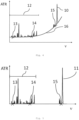
- Figures 4 and 5 illustrate how the electrical signals of the chosen infrared light detectors can be used to correct the electrical signals of all the other infrared light detectors.
- Figure 4 shows an ATR spectrum 10 before a correction
- Figure 5 shows an ATR spectrum 11 after the correction.
- the inverse of all the electrical signals is used and in case of Figure 4 plotted versus the frequency v.
- Figures 4 and 5 also show the wavelength range 12 of the spectrum that can be measured by the line array 6.
- the ATR spectrometer 1 is adapted to use the electrical signals of a plurality of the chosen infrared light detectors to generate a wavelength dependent function 16 and to correct the electrical signals of all the other infrared light detectors using the wavelength dependent function 16.
- At least one of the chosen infrared light detectors is one of the infrared light detectors of the line array 6.
- two of the chosen infrared light detectors are chosen from the line array 6.
- At least one of the chosen infrared light detectors is one of the single infrared light detectors 7.
- only one of the single infrared light detectors is one of the chosen infrared light detectors. Consequently, according to Figures 4 and 5 , the ATR spectrometer 1 comprises three of the chosen infrared light detectors.
- the wavelength filter 9 corresponding to one of the chosen infrared light detectors, namely the single infrared light detector 7, is a bandpass filter and has a transmission in a wavelength region that is outside of the spectrum that can be measured by the line array 6 (see Figures 4 and 5 ).
- the chosen infrared light detectors are chosen such that their corresponding detectable wavelength ranges are in wavelength regions where the sample has substantially no absorption. Since the ATR spectrometer 1 has three of the chosen infrared light detectors, the ATR spectrometer 1 is adapted to measure three different wavelength regions in the ATR spectrum with substantially no absorption. As it can be seen in Figures 4 and 5 , a first wavelength region 13 corresponds to one of the two chosen infrared light detectors of the line array 6, a second wavelength region 14 corresponds to the other one of the two chosen infrared light detectors of the line array 6 and a third wavelength region 15 corresponds to the one single infrared light detector 7.
- wavelength regions it is conceivable to measure an extinction spectrum of the sample or of a reference sample being similar to the sample by means of an FTIR spectrometer. The wavelength regions with substantially no absorption can then be determined from the extinction spectrum.
- the ATR spectrometer 1 is adapted to fit the wavelength dependent function 16 to the inverse of the signal values output by the chosen infrared light detectors.
- the wavelength dependent function 16 is subtracted from the ATR spectrum 10 of Figure 4 . The subtraction results in the ATR spectrum 11 of Figure 5 . In this manner, spectral drifts of the at least one infrared light source 5 can be compensated and simultaneously the contribution of scattering can be eliminated from the ATR spectrum 10.
- the chemical composition of the sample can then be analysed by applying Lambert-Beer's law to at least one part of the spectrum 11 after the correction and/or by applying chemometric methods to the spectrum 11 after the correction.
Landscapes
- Physics & Mathematics (AREA)
- Spectroscopy & Molecular Physics (AREA)
- General Physics & Mathematics (AREA)
- Biochemistry (AREA)
- Chemical & Material Sciences (AREA)
- Analytical Chemistry (AREA)
- Life Sciences & Earth Sciences (AREA)
- General Health & Medical Sciences (AREA)
- Health & Medical Sciences (AREA)
- Immunology (AREA)
- Pathology (AREA)
- Engineering & Computer Science (AREA)
- Mathematical Physics (AREA)
- Theoretical Computer Science (AREA)
- Investigating Or Analysing Materials By Optical Means (AREA)
Applications Claiming Priority (2)
| Application Number | Priority Date | Filing Date | Title |
|---|---|---|---|
| DE102017104872.3A DE102017104872A1 (de) | 2017-03-08 | 2017-03-08 | ATR Spektrometer und Verfahren zum Analysieren der chemischen Zusammensetzung einer Probe |
| PCT/EP2018/055319 WO2018162398A1 (en) | 2017-03-08 | 2018-03-05 | Atr spectrometer and method for analysing the chemical composition of a sample |
Publications (2)
| Publication Number | Publication Date |
|---|---|
| EP3593118A1 EP3593118A1 (en) | 2020-01-15 |
| EP3593118B1 true EP3593118B1 (en) | 2024-10-30 |
Family
ID=61691925
Family Applications (1)
| Application Number | Title | Priority Date | Filing Date |
|---|---|---|---|
| EP18712092.8A Active EP3593118B1 (en) | 2017-03-08 | 2018-03-05 | Atr spectrometer and method for analysing the chemical composition of a sample |
Country Status (5)
| Country | Link |
|---|---|
| US (1) | US11248958B2 (https=) |
| EP (1) | EP3593118B1 (https=) |
| JP (1) | JP7241021B2 (https=) |
| DE (1) | DE102017104872A1 (https=) |
| WO (1) | WO2018162398A1 (https=) |
Families Citing this family (2)
| Publication number | Priority date | Publication date | Assignee | Title |
|---|---|---|---|---|
| TWI809530B (zh) * | 2021-10-15 | 2023-07-21 | 譜鉅科技股份有限公司 | 藥物掃描與辨識系統及其使用方法 |
| CN115993342A (zh) | 2021-10-15 | 2023-04-21 | 谱钜科技股份有限公司 | 药物扫描与辨识系统及其使用方法 |
Citations (1)
| Publication number | Priority date | Publication date | Assignee | Title |
|---|---|---|---|---|
| DE102013005372A1 (de) * | 2013-03-28 | 2014-10-02 | Spectrolytic GmbH | Vorrichtung zur spektroskopischen Messwerterfassung von physikalischen und/oder chemischen Parametern eines Messobjektes |
Family Cites Families (16)
| Publication number | Priority date | Publication date | Assignee | Title |
|---|---|---|---|---|
| JPS59171837A (ja) | 1983-03-19 | 1984-09-28 | Japan Spectroscopic Co | 赤外分光装置による透過率測定におけるデ−タ補正方法 |
| US5460973A (en) | 1994-12-20 | 1995-10-24 | Ceramoptec Industries Inc. | Method for continuous determination of volatile impurities in contaminated medium |
| US5731581A (en) * | 1995-03-13 | 1998-03-24 | Ohmeda Inc. | Apparatus for automatic identification of gas samples |
| US20030176775A1 (en) | 1998-10-13 | 2003-09-18 | Medoptix, Inc. | Cleaning kit for an infrared glucose measurement system |
| JP4127195B2 (ja) | 2003-11-21 | 2008-07-30 | コニカミノルタセンシング株式会社 | 分光強度測定装置およびその校正方法ならびに分光反射特性測定装置およびその校正方法 |
| JP2008197043A (ja) | 2007-02-15 | 2008-08-28 | Yokogawa Electric Corp | 光信号測定装置 |
| EP2133478A3 (en) | 2008-02-27 | 2011-10-05 | Jsm Healthcare Inc | Apparatus for analyzing components of urine by using atr and method thereof |
| DE102008054056A1 (de) | 2008-10-31 | 2010-05-06 | Carl Zeiss Microimaging Gmbh | Spektrometrische Anordnung und Verfahren zum Ermitteln eines Temperaturwerts für einen Detektor eines Spektrometers |
| DE102009027134A1 (de) * | 2009-06-24 | 2010-12-30 | Robert Bosch Gmbh | Spektroskopischer Sensor und Messverfahren zur Bestimmung mindestens einer Konzentration |
| AT512291B1 (de) | 2012-02-20 | 2013-07-15 | Anton Paar Gmbh | Verfahren und vorrichtung zur bestimmung des co2-gehalts in einer flüssigkeit |
| US10001437B2 (en) | 2013-10-04 | 2018-06-19 | The Research Foundation For The State University Of New York | Spectroscopy for gunshot residue analysis |
| DE102013114244B3 (de) * | 2013-12-17 | 2015-01-22 | Pyreos Ltd. | ATR-Infrarotspektrometer |
| US9182280B1 (en) | 2014-08-08 | 2015-11-10 | Thermo Scientific Portable Analytical Instruments Inc. | Method for reducing frequency of taking background/reference spectra in FTIR or FTIR-ATR spectroscopy and handheld measurement device embodying same |
| GB2530098B (en) * | 2014-09-15 | 2017-02-22 | Schlumberger Holdings | Mid-infrared acid sensor |
| DE102014115502A1 (de) * | 2014-10-24 | 2016-04-28 | Pyreos Ltd. | Hautmessgerät und Armbanduhr |
| US10066990B2 (en) * | 2015-07-09 | 2018-09-04 | Verifood, Ltd. | Spatially variable filter systems and methods |
-
2017
- 2017-03-08 DE DE102017104872.3A patent/DE102017104872A1/de not_active Withdrawn
-
2018
- 2018-03-05 EP EP18712092.8A patent/EP3593118B1/en active Active
- 2018-03-05 US US16/491,068 patent/US11248958B2/en active Active
- 2018-03-05 JP JP2019548903A patent/JP7241021B2/ja active Active
- 2018-03-05 WO PCT/EP2018/055319 patent/WO2018162398A1/en not_active Ceased
Patent Citations (1)
| Publication number | Priority date | Publication date | Assignee | Title |
|---|---|---|---|---|
| DE102013005372A1 (de) * | 2013-03-28 | 2014-10-02 | Spectrolytic GmbH | Vorrichtung zur spektroskopischen Messwerterfassung von physikalischen und/oder chemischen Parametern eines Messobjektes |
Also Published As
| Publication number | Publication date |
|---|---|
| US11248958B2 (en) | 2022-02-15 |
| US20200011735A1 (en) | 2020-01-09 |
| WO2018162398A1 (en) | 2018-09-13 |
| JP7241021B2 (ja) | 2023-03-16 |
| JP2020513216A (ja) | 2020-05-07 |
| DE102017104872A1 (de) | 2018-09-13 |
| EP3593118A1 (en) | 2020-01-15 |
Similar Documents
| Publication | Publication Date | Title |
|---|---|---|
| US9816934B2 (en) | Laser induced breakdown spectroscopy (LIBS) apparatus with automatic wavelength calibration | |
| CN110730903B (zh) | 光谱测定方法、光谱测定装置以及宽波段脉冲光源单元 | |
| US6774368B2 (en) | Dispersive near-infrared spectrometer with automatic wavelength calibration | |
| US10151633B2 (en) | High accuracy absorbance spectrophotometers | |
| US11193827B2 (en) | Method and apparatus for identifying background fluorescence using spread spectrum excitation-source broadening in Raman spectroscopy | |
| CN112823279A (zh) | 显微分光装置、以及显微分光方法 | |
| CN103221802A (zh) | 分光光度计 | |
| US20050236563A1 (en) | Dispersive near-infrared spectrometer with automatic wavelength calibration | |
| EP3593118B1 (en) | Atr spectrometer and method for analysing the chemical composition of a sample | |
| US12566129B2 (en) | Spectroscopic measurement method | |
| US11879846B2 (en) | Raman spectroscopy method and apparatus using broadband excitation light | |
| CN102200581A (zh) | 使用单色仪分光的高精度的水汽拉曼系统及定标方法 | |
| EP3254073B1 (en) | A spectrometer system and a method for compensating for time periodic perturbations of an interferogram generated by the spectrometer system | |
| US7796261B2 (en) | Spectrophotometer | |
| KR101683465B1 (ko) | 다중 선방출원을 이용한 실시간 분광기 보정방법 | |
| JP2020513216A5 (https=) | ||
| US11060972B2 (en) | Method for analysing a gas | |
| US9030666B2 (en) | Non-dispersive gas analyzer | |
| US20070064230A1 (en) | Broadband laser spectroscopy | |
| US20240328939A1 (en) | Method and system for analysing a sample based on data | |
| JP5994593B2 (ja) | 分光光度計 | |
| JP7184924B2 (ja) | 水中の炭化水素汚染の測定 | |
| CN114270171B (zh) | 校正光谱仪中的振幅变化的方法 | |
| JP2013160651A (ja) | ライン分光測定装置 | |
| Wiesent et al. | Linear variable filter based oil condition monitoring systems for offshore windturbines |
Legal Events
| Date | Code | Title | Description |
|---|---|---|---|
| STAA | Information on the status of an ep patent application or granted ep patent |
Free format text: STATUS: UNKNOWN |
|
| STAA | Information on the status of an ep patent application or granted ep patent |
Free format text: STATUS: THE INTERNATIONAL PUBLICATION HAS BEEN MADE |
|
| PUAI | Public reference made under article 153(3) epc to a published international application that has entered the european phase |
Free format text: ORIGINAL CODE: 0009012 |
|
| STAA | Information on the status of an ep patent application or granted ep patent |
Free format text: STATUS: REQUEST FOR EXAMINATION WAS MADE |
|
| 17P | Request for examination filed |
Effective date: 20190917 |
|
| AK | Designated contracting states |
Kind code of ref document: A1 Designated state(s): AL AT BE BG CH CY CZ DE DK EE ES FI FR GB GR HR HU IE IS IT LI LT LU LV MC MK MT NL NO PL PT RO RS SE SI SK SM TR |
|
| AX | Request for extension of the european patent |
Extension state: BA ME |
|
| DAV | Request for validation of the european patent (deleted) | ||
| DAX | Request for extension of the european patent (deleted) | ||
| RAP3 | Party data changed (applicant data changed or rights of an application transferred) |
Owner name: PYREOS LTD. |
|
| STAA | Information on the status of an ep patent application or granted ep patent |
Free format text: STATUS: EXAMINATION IS IN PROGRESS |
|
| 17Q | First examination report despatched |
Effective date: 20211021 |
|
| RAP1 | Party data changed (applicant data changed or rights of an application transferred) |
Owner name: AVAGO TECHNOLOGIES INTERNATIONAL SALES PTE. LIMITED |
|
| GRAP | Despatch of communication of intention to grant a patent |
Free format text: ORIGINAL CODE: EPIDOSNIGR1 |
|
| STAA | Information on the status of an ep patent application or granted ep patent |
Free format text: STATUS: GRANT OF PATENT IS INTENDED |
|
| RIC1 | Information provided on ipc code assigned before grant |
Ipc: G01N 21/3577 20140101ALN20240424BHEP Ipc: G01N 21/3563 20140101ALN20240424BHEP Ipc: G01J 3/02 20060101ALI20240424BHEP Ipc: G01J 3/36 20060101ALI20240424BHEP Ipc: G01N 21/552 20140101ALI20240424BHEP Ipc: G01J 3/28 20060101ALI20240424BHEP Ipc: G01N 21/27 20060101AFI20240424BHEP |
|
| INTG | Intention to grant announced |
Effective date: 20240522 |
|
| GRAS | Grant fee paid |
Free format text: ORIGINAL CODE: EPIDOSNIGR3 |
|
| GRAA | (expected) grant |
Free format text: ORIGINAL CODE: 0009210 |
|
| STAA | Information on the status of an ep patent application or granted ep patent |
Free format text: STATUS: THE PATENT HAS BEEN GRANTED |
|
| AK | Designated contracting states |
Kind code of ref document: B1 Designated state(s): AL AT BE BG CH CY CZ DE DK EE ES FI FR GB GR HR HU IE IS IT LI LT LU LV MC MK MT NL NO PL PT RO RS SE SI SK SM TR |
|
| REG | Reference to a national code |
Ref country code: GB Ref legal event code: FG4D |
|
| REG | Reference to a national code |
Ref country code: CH Ref legal event code: EP |
|
| REG | Reference to a national code |
Ref country code: IE Ref legal event code: FG4D |
|
| REG | Reference to a national code |
Ref country code: DE Ref legal event code: R096 Ref document number: 602018075942 Country of ref document: DE |
|
| REG | Reference to a national code |
Ref country code: NL Ref legal event code: FP |
|
| REG | Reference to a national code |
Ref country code: LT Ref legal event code: MG9D |
|
| PG25 | Lapsed in a contracting state [announced via postgrant information from national office to epo] |
Ref country code: IS Free format text: LAPSE BECAUSE OF FAILURE TO SUBMIT A TRANSLATION OF THE DESCRIPTION OR TO PAY THE FEE WITHIN THE PRESCRIBED TIME-LIMIT Effective date: 20250228 Ref country code: HR Free format text: LAPSE BECAUSE OF FAILURE TO SUBMIT A TRANSLATION OF THE DESCRIPTION OR TO PAY THE FEE WITHIN THE PRESCRIBED TIME-LIMIT Effective date: 20241030 Ref country code: PT Free format text: LAPSE BECAUSE OF FAILURE TO SUBMIT A TRANSLATION OF THE DESCRIPTION OR TO PAY THE FEE WITHIN THE PRESCRIBED TIME-LIMIT Effective date: 20250228 |
|
| PG25 | Lapsed in a contracting state [announced via postgrant information from national office to epo] |
Ref country code: FI Free format text: LAPSE BECAUSE OF FAILURE TO SUBMIT A TRANSLATION OF THE DESCRIPTION OR TO PAY THE FEE WITHIN THE PRESCRIBED TIME-LIMIT Effective date: 20241030 |
|
| REG | Reference to a national code |
Ref country code: AT Ref legal event code: MK05 Ref document number: 1737318 Country of ref document: AT Kind code of ref document: T Effective date: 20241030 |
|
| PG25 | Lapsed in a contracting state [announced via postgrant information from national office to epo] |
Ref country code: BG Free format text: LAPSE BECAUSE OF FAILURE TO SUBMIT A TRANSLATION OF THE DESCRIPTION OR TO PAY THE FEE WITHIN THE PRESCRIBED TIME-LIMIT Effective date: 20241030 |
|
| PG25 | Lapsed in a contracting state [announced via postgrant information from national office to epo] |
Ref country code: ES Free format text: LAPSE BECAUSE OF FAILURE TO SUBMIT A TRANSLATION OF THE DESCRIPTION OR TO PAY THE FEE WITHIN THE PRESCRIBED TIME-LIMIT Effective date: 20241030 |
|
| PG25 | Lapsed in a contracting state [announced via postgrant information from national office to epo] |
Ref country code: NO Free format text: LAPSE BECAUSE OF FAILURE TO SUBMIT A TRANSLATION OF THE DESCRIPTION OR TO PAY THE FEE WITHIN THE PRESCRIBED TIME-LIMIT Effective date: 20250130 |
|
| PG25 | Lapsed in a contracting state [announced via postgrant information from national office to epo] |
Ref country code: AT Free format text: LAPSE BECAUSE OF FAILURE TO SUBMIT A TRANSLATION OF THE DESCRIPTION OR TO PAY THE FEE WITHIN THE PRESCRIBED TIME-LIMIT Effective date: 20241030 Ref country code: LV Free format text: LAPSE BECAUSE OF FAILURE TO SUBMIT A TRANSLATION OF THE DESCRIPTION OR TO PAY THE FEE WITHIN THE PRESCRIBED TIME-LIMIT Effective date: 20241030 Ref country code: GR Free format text: LAPSE BECAUSE OF FAILURE TO SUBMIT A TRANSLATION OF THE DESCRIPTION OR TO PAY THE FEE WITHIN THE PRESCRIBED TIME-LIMIT Effective date: 20250131 |
|
| PG25 | Lapsed in a contracting state [announced via postgrant information from national office to epo] |
Ref country code: PL Free format text: LAPSE BECAUSE OF FAILURE TO SUBMIT A TRANSLATION OF THE DESCRIPTION OR TO PAY THE FEE WITHIN THE PRESCRIBED TIME-LIMIT Effective date: 20241030 |
|
| PG25 | Lapsed in a contracting state [announced via postgrant information from national office to epo] |
Ref country code: RS Free format text: LAPSE BECAUSE OF FAILURE TO SUBMIT A TRANSLATION OF THE DESCRIPTION OR TO PAY THE FEE WITHIN THE PRESCRIBED TIME-LIMIT Effective date: 20250130 |
|
| PG25 | Lapsed in a contracting state [announced via postgrant information from national office to epo] |
Ref country code: SM Free format text: LAPSE BECAUSE OF FAILURE TO SUBMIT A TRANSLATION OF THE DESCRIPTION OR TO PAY THE FEE WITHIN THE PRESCRIBED TIME-LIMIT Effective date: 20241030 |
|
| PG25 | Lapsed in a contracting state [announced via postgrant information from national office to epo] |
Ref country code: DK Free format text: LAPSE BECAUSE OF FAILURE TO SUBMIT A TRANSLATION OF THE DESCRIPTION OR TO PAY THE FEE WITHIN THE PRESCRIBED TIME-LIMIT Effective date: 20241030 |
|
| PG25 | Lapsed in a contracting state [announced via postgrant information from national office to epo] |
Ref country code: EE Free format text: LAPSE BECAUSE OF FAILURE TO SUBMIT A TRANSLATION OF THE DESCRIPTION OR TO PAY THE FEE WITHIN THE PRESCRIBED TIME-LIMIT Effective date: 20241030 |
|
| PG25 | Lapsed in a contracting state [announced via postgrant information from national office to epo] |
Ref country code: RO Free format text: LAPSE BECAUSE OF FAILURE TO SUBMIT A TRANSLATION OF THE DESCRIPTION OR TO PAY THE FEE WITHIN THE PRESCRIBED TIME-LIMIT Effective date: 20241030 |
|
| PG25 | Lapsed in a contracting state [announced via postgrant information from national office to epo] |
Ref country code: SK Free format text: LAPSE BECAUSE OF FAILURE TO SUBMIT A TRANSLATION OF THE DESCRIPTION OR TO PAY THE FEE WITHIN THE PRESCRIBED TIME-LIMIT Effective date: 20241030 |
|
| PG25 | Lapsed in a contracting state [announced via postgrant information from national office to epo] |
Ref country code: CZ Free format text: LAPSE BECAUSE OF FAILURE TO SUBMIT A TRANSLATION OF THE DESCRIPTION OR TO PAY THE FEE WITHIN THE PRESCRIBED TIME-LIMIT Effective date: 20241030 |
|
| PG25 | Lapsed in a contracting state [announced via postgrant information from national office to epo] |
Ref country code: IT Free format text: LAPSE BECAUSE OF FAILURE TO SUBMIT A TRANSLATION OF THE DESCRIPTION OR TO PAY THE FEE WITHIN THE PRESCRIBED TIME-LIMIT Effective date: 20241030 |
|
| REG | Reference to a national code |
Ref country code: DE Ref legal event code: R097 Ref document number: 602018075942 Country of ref document: DE |
|
| PLBE | No opposition filed within time limit |
Free format text: ORIGINAL CODE: 0009261 |
|
| STAA | Information on the status of an ep patent application or granted ep patent |
Free format text: STATUS: NO OPPOSITION FILED WITHIN TIME LIMIT |
|
| PG25 | Lapsed in a contracting state [announced via postgrant information from national office to epo] |
Ref country code: SE Free format text: LAPSE BECAUSE OF FAILURE TO SUBMIT A TRANSLATION OF THE DESCRIPTION OR TO PAY THE FEE WITHIN THE PRESCRIBED TIME-LIMIT Effective date: 20241030 |
|
| 26N | No opposition filed |
Effective date: 20250731 |
|
| PG25 | Lapsed in a contracting state [announced via postgrant information from national office to epo] |
Ref country code: MC Free format text: LAPSE BECAUSE OF FAILURE TO SUBMIT A TRANSLATION OF THE DESCRIPTION OR TO PAY THE FEE WITHIN THE PRESCRIBED TIME-LIMIT Effective date: 20241030 |
|
| REG | Reference to a national code |
Ref country code: CH Ref legal event code: H13 Free format text: ST27 STATUS EVENT CODE: U-0-0-H10-H13 (AS PROVIDED BY THE NATIONAL OFFICE) Effective date: 20251023 |
|
| PG25 | Lapsed in a contracting state [announced via postgrant information from national office to epo] |
Ref country code: LU Free format text: LAPSE BECAUSE OF NON-PAYMENT OF DUE FEES Effective date: 20250305 |
|
| GBPC | Gb: european patent ceased through non-payment of renewal fee |
Effective date: 20250305 |
|
| REG | Reference to a national code |
Ref country code: BE Ref legal event code: MM Effective date: 20250331 |
|
| PG25 | Lapsed in a contracting state [announced via postgrant information from national office to epo] |
Ref country code: GB Free format text: LAPSE BECAUSE OF NON-PAYMENT OF DUE FEES Effective date: 20250305 |
|
| PG25 | Lapsed in a contracting state [announced via postgrant information from national office to epo] |
Ref country code: BE Free format text: LAPSE BECAUSE OF NON-PAYMENT OF DUE FEES Effective date: 20250331 |
|
| PG25 | Lapsed in a contracting state [announced via postgrant information from national office to epo] |
Ref country code: CH Free format text: LAPSE BECAUSE OF NON-PAYMENT OF DUE FEES Effective date: 20250331 |
|
| PG25 | Lapsed in a contracting state [announced via postgrant information from national office to epo] |
Ref country code: IE Free format text: LAPSE BECAUSE OF NON-PAYMENT OF DUE FEES Effective date: 20250305 |
|
| PGFP | Annual fee paid to national office [announced via postgrant information from national office to epo] |
Ref country code: NL Payment date: 20260219 Year of fee payment: 9 |
|
| PGFP | Annual fee paid to national office [announced via postgrant information from national office to epo] |
Ref country code: DE Payment date: 20260310 Year of fee payment: 9 |
|
| PGFP | Annual fee paid to national office [announced via postgrant information from national office to epo] |
Ref country code: FR Payment date: 20260220 Year of fee payment: 9 |