EP3592973B1 - Procédé d'installation de composants d'une turbine éolienne et dispositif de levage - Google Patents
Procédé d'installation de composants d'une turbine éolienne et dispositif de levage Download PDFInfo
- Publication number
- EP3592973B1 EP3592973B1 EP17837862.6A EP17837862A EP3592973B1 EP 3592973 B1 EP3592973 B1 EP 3592973B1 EP 17837862 A EP17837862 A EP 17837862A EP 3592973 B1 EP3592973 B1 EP 3592973B1
- Authority
- EP
- European Patent Office
- Prior art keywords
- lifting
- component
- attached
- stabilization device
- stabilization
- Prior art date
- Legal status (The legal status is an assumption and is not a legal conclusion. Google has not performed a legal analysis and makes no representation as to the accuracy of the status listed.)
- Active
Links
- 238000000034 method Methods 0.000 title claims description 8
- 230000006641 stabilisation Effects 0.000 claims description 61
- 238000011105 stabilization Methods 0.000 claims description 60
- 230000000087 stabilizing effect Effects 0.000 claims description 12
- 238000005259 measurement Methods 0.000 claims description 9
- 230000000694 effects Effects 0.000 claims description 6
- 238000009434 installation Methods 0.000 claims description 6
- 238000013016 damping Methods 0.000 description 1
- 230000001939 inductive effect Effects 0.000 description 1
- 230000003993 interaction Effects 0.000 description 1
- 238000012423 maintenance Methods 0.000 description 1
Images


Classifications
-
- B—PERFORMING OPERATIONS; TRANSPORTING
- B66—HOISTING; LIFTING; HAULING
- B66C—CRANES; LOAD-ENGAGING ELEMENTS OR DEVICES FOR CRANES, CAPSTANS, WINCHES, OR TACKLES
- B66C13/00—Other constructional features or details
- B66C13/04—Auxiliary devices for controlling movements of suspended loads, or preventing cable slack
- B66C13/06—Auxiliary devices for controlling movements of suspended loads, or preventing cable slack for minimising or preventing longitudinal or transverse swinging of loads
- B66C13/063—Auxiliary devices for controlling movements of suspended loads, or preventing cable slack for minimising or preventing longitudinal or transverse swinging of loads electrical
-
- F—MECHANICAL ENGINEERING; LIGHTING; HEATING; WEAPONS; BLASTING
- F03—MACHINES OR ENGINES FOR LIQUIDS; WIND, SPRING, OR WEIGHT MOTORS; PRODUCING MECHANICAL POWER OR A REACTIVE PROPULSIVE THRUST, NOT OTHERWISE PROVIDED FOR
- F03D—WIND MOTORS
- F03D13/00—Assembly, mounting or commissioning of wind motors; Arrangements specially adapted for transporting wind motor components
- F03D13/10—Assembly of wind motors; Arrangements for erecting wind motors
-
- B—PERFORMING OPERATIONS; TRANSPORTING
- B66—HOISTING; LIFTING; HAULING
- B66C—CRANES; LOAD-ENGAGING ELEMENTS OR DEVICES FOR CRANES, CAPSTANS, WINCHES, OR TACKLES
- B66C1/00—Load-engaging elements or devices attached to lifting or lowering gear of cranes or adapted for connection therewith for transmitting lifting forces to articles or groups of articles
- B66C1/10—Load-engaging elements or devices attached to lifting or lowering gear of cranes or adapted for connection therewith for transmitting lifting forces to articles or groups of articles by mechanical means
- B66C1/108—Load-engaging elements or devices attached to lifting or lowering gear of cranes or adapted for connection therewith for transmitting lifting forces to articles or groups of articles by mechanical means for lifting parts of wind turbines
-
- B—PERFORMING OPERATIONS; TRANSPORTING
- B66—HOISTING; LIFTING; HAULING
- B66C—CRANES; LOAD-ENGAGING ELEMENTS OR DEVICES FOR CRANES, CAPSTANS, WINCHES, OR TACKLES
- B66C13/00—Other constructional features or details
- B66C13/04—Auxiliary devices for controlling movements of suspended loads, or preventing cable slack
- B66C13/06—Auxiliary devices for controlling movements of suspended loads, or preventing cable slack for minimising or preventing longitudinal or transverse swinging of loads
-
- B—PERFORMING OPERATIONS; TRANSPORTING
- B66—HOISTING; LIFTING; HAULING
- B66C—CRANES; LOAD-ENGAGING ELEMENTS OR DEVICES FOR CRANES, CAPSTANS, WINCHES, OR TACKLES
- B66C23/00—Cranes comprising essentially a beam, boom, or triangular structure acting as a cantilever and mounted for translatory of swinging movements in vertical or horizontal planes or a combination of such movements, e.g. jib-cranes, derricks, tower cranes
- B66C23/18—Cranes comprising essentially a beam, boom, or triangular structure acting as a cantilever and mounted for translatory of swinging movements in vertical or horizontal planes or a combination of such movements, e.g. jib-cranes, derricks, tower cranes specially adapted for use in particular purposes
- B66C23/185—Cranes comprising essentially a beam, boom, or triangular structure acting as a cantilever and mounted for translatory of swinging movements in vertical or horizontal planes or a combination of such movements, e.g. jib-cranes, derricks, tower cranes specially adapted for use in particular purposes for use erecting wind turbines
-
- B—PERFORMING OPERATIONS; TRANSPORTING
- B66—HOISTING; LIFTING; HAULING
- B66C—CRANES; LOAD-ENGAGING ELEMENTS OR DEVICES FOR CRANES, CAPSTANS, WINCHES, OR TACKLES
- B66C2700/00—Cranes
- B66C2700/03—Cranes with arms or jibs; Multiple cranes
- B66C2700/0321—Travelling cranes
- B66C2700/0357—Cranes on road or off-road vehicles, on trailers or towed vehicles; Cranes on wheels or crane-trucks
- B66C2700/0364—Cranes on road or off-road vehicles, on trailers or towed vehicles; Cranes on wheels or crane-trucks with a slewing arm
- B66C2700/0371—Cranes on road or off-road vehicles, on trailers or towed vehicles; Cranes on wheels or crane-trucks with a slewing arm on a turntable
-
- F—MECHANICAL ENGINEERING; LIGHTING; HEATING; WEAPONS; BLASTING
- F05—INDEXING SCHEMES RELATING TO ENGINES OR PUMPS IN VARIOUS SUBCLASSES OF CLASSES F01-F04
- F05B—INDEXING SCHEME RELATING TO WIND, SPRING, WEIGHT, INERTIA OR LIKE MOTORS, TO MACHINES OR ENGINES FOR LIQUIDS COVERED BY SUBCLASSES F03B, F03D AND F03G
- F05B2230/00—Manufacture
- F05B2230/60—Assembly methods
- F05B2230/61—Assembly methods using auxiliary equipment for lifting or holding
-
- Y—GENERAL TAGGING OF NEW TECHNOLOGICAL DEVELOPMENTS; GENERAL TAGGING OF CROSS-SECTIONAL TECHNOLOGIES SPANNING OVER SEVERAL SECTIONS OF THE IPC; TECHNICAL SUBJECTS COVERED BY FORMER USPC CROSS-REFERENCE ART COLLECTIONS [XRACs] AND DIGESTS
- Y02—TECHNOLOGIES OR APPLICATIONS FOR MITIGATION OR ADAPTATION AGAINST CLIMATE CHANGE
- Y02E—REDUCTION OF GREENHOUSE GAS [GHG] EMISSIONS, RELATED TO ENERGY GENERATION, TRANSMISSION OR DISTRIBUTION
- Y02E10/00—Energy generation through renewable energy sources
- Y02E10/70—Wind energy
- Y02E10/72—Wind turbines with rotation axis in wind direction
-
- Y—GENERAL TAGGING OF NEW TECHNOLOGICAL DEVELOPMENTS; GENERAL TAGGING OF CROSS-SECTIONAL TECHNOLOGIES SPANNING OVER SEVERAL SECTIONS OF THE IPC; TECHNICAL SUBJECTS COVERED BY FORMER USPC CROSS-REFERENCE ART COLLECTIONS [XRACs] AND DIGESTS
- Y02—TECHNOLOGIES OR APPLICATIONS FOR MITIGATION OR ADAPTATION AGAINST CLIMATE CHANGE
- Y02P—CLIMATE CHANGE MITIGATION TECHNOLOGIES IN THE PRODUCTION OR PROCESSING OF GOODS
- Y02P70/00—Climate change mitigation technologies in the production process for final industrial or consumer products
- Y02P70/50—Manufacturing or production processes characterised by the final manufactured product
Definitions
- the invention relates to a method for installing components of a wind turbine, with a lifting device for lifting the respective component hanging at the lifting device via at least one cable.
- KR 2015 0102518 A JP 2016 210607 A , JP 2015 101413 A , and DE 2009847 .
- Building a wind turbine involves the installation of several separate components which usually need to be lifted by means of a lifting device like a crane. For building the tower several separate tower segments are to be lifted and stacked above one another. After building the tower the nacelle with the gear box and other preinstalled parts of the drive train needs to be installed. Finally the generator and the hub are installed and respective rotor blades are fixed to the hub.
- At least one stabilization device is stabilizing the components against movements induced by external forces by means of a gyroscopic effect.
- a stabilization device is provided at the lifting arrangement in the region which can start to swing or vibrate or rotate due to external forces acting on the component hanging at the lifting device.
- This stabilization device is able to automatically stabilize the component against vibrations, rotations or any kind of movement due to a certain extent by means of a gyroscopic effect.
- This stabilization device is activated when the lifting device starts to lift the component. As soon as the component starts to swing or move in a direction different to the moving direction effected by the lifting device the stabilization device starts to provide counterforces in reaction of the external forces acting on the component. These counterforces are created by means of a gyroscopic effect.
- the stabilization device is a gyroscopic stabilization or damping device.
- the stabilization device can also be remote controlled by a worker or operator to precisely orientate and position the component. This could also be done automatically by means of an automatic control unit which controls the stabilization device to hold the component in a present direction or orientation.
- the stabilization itself is provided by means of a rotating flywheel which is tilted by means of a tilting device around at least one axis with a perpendicular orientation to the axis of rotation of the flywheel.
- the stabilization device which can also be called a control moment gyroscope, comprises the rotating flywheel which is enclosed in a rigid casing. The flywheel spins at speeds up several hundred kilometres per hour around its centre axis.
- a tilting device which tilts the casing around at least one axis perpendicular to the central rotation axis of the flywheel tilts the casing and the flywheel for changing the momentum created by the flywheel, which tilting action results in the counterforce.
- This control moment or control force which can also be named as a gyroscopic resistance force, has a certain direction and extinguishes the external force acting on the component.
- This gyroscopic stabilization device is designed to produce high moments or reaction forces which can counter or extinguish the external forces to a high extent or preferably completely.
- the sensor device which provides measurement values regarding the force induced movements like vibrations or rotations with the stabilization device being controlled based on the measurement values.
- the sensor device can be part of or attached to the stabilization device in a region which is not moved by the tilting device, as the sensor device is used for measuring any kind of vibrations or swinging or rotating movement.
- the stabilization device is attached to a bunch of cables connecting a fixation means of the lifting device to a handling tool such that the stabilizing device is attached between the fixation means and the handling tool.
- the component is for example a rotor blade, a nacelle, a hub, a tower section, a generator or a gear box, with this enumeration is not conclusive.
- the invention furthermore relates to a lifting arrangement for lifting components during the installation of a wind turbine, comprising a lifting device and a component attached to the lifting device via at least one cable, wherein at least one stabilization device is provided for stabilizing the component against movements induced by external forces by means of a gyroscopic effect.
- the stabilization device comprises a rotating flywheel and a tilting device for tilting the flywheel around at least one axis with a perpendicular orientation to the axis of rotation of the flywheel. It is certainly possible that the rotating flywheel, which is encased in a closed casing, can be tilted also around a second axis, which is also perpendicular to the axis of rotation of the flywheel, so that in total three axis being perpendicular to each other are provided.
- the stabilization device gyroscope can also be called a control moment gyroscope.
- a sensor device for providing measurement values regarding the force induced movements like vibrations or rotations with the stabilization device being controlled based on the measurement values.
- the stabilization device of the inventive lifting device is attached to a bunch of cables connecting a fixation means of the lifting device to a handling tool such that the stabilizing device is attached between the fixation means and the handling tool.
- the component being lifted by means of the lifting device is a rotor blade, a nacelle, a hub, a tower section, a generator or a gear box.
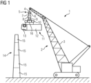
- Fig. 1 shows a non-claimed lifting arrangement 1 comprising a lifting device 2, here a crane 3.
- the lifting device 2 comprises at least one lifting cable 4, to which a fixation means 5, here a hook 6, is attached.
- the hook 6 is connected via further cables 7 to a fixation tool 8.
- This fixation tool is for example a fixation frame or a fixation yoke, to which via further cables 9 a handling tool 10 is attached.
- the handling tool 10 also for example a handling frame or handling yoke, is connected to a component 11, for example a nacelle 12 comprising a hub 13, which shall be installed to a tower installation 14 being built from several tower segments 15 stacked above one another. These tower segments 15 have also been lifted and installed by means of the lifting arrangement 1.
- the lifting arrangement 1 further comprises a stabilization device 16, which is used for stabilizing the component 11 respectively the complete system comprising all items hanging at the hook 6 against movements like or vibrations or rotations due to external forces, especially strong wind forces acting on the component 11.
- a stabilization device 16 which is used for stabilizing the component 11 respectively the complete system comprising all items hanging at the hook 6 against movements like or vibrations or rotations due to external forces, especially strong wind forces acting on the component 11.
- the stabilization device creates forces or moments which are able to counter or extinguish the external forces inducing the movement like vibrations or rotations, and thus the movement itself.
- the stabilization device comprises a flywheel rotating at high speed around a central axis.
- a tilting device can tilt the casing in which the rotating flywheel is arranged around at least one axis, which axis is perpendicular to the axis of rotation of the flywheel. It is possible that the tilting device can tilt the casing also around a second axis, which is itself perpendicular to the first tilting axis and the rotation axis, thus three axes being perpendicular to each other are provided.
- This stabilization enables a very stable, non-swinging and non-rotating lifting and positioning action of the component 11 relative to a previously installed component, to which the component 11 shall be attached.
- Fig. 2 shows a first example of a part of a non-claimed lifting arrangement 1. It shows the component 11 in form of a rotor blade 17 being firmly attached to a handling tool 10.
- the handling tool 10 is attached via cables 9 to a fixation tool 8, which is attached by means of cables 7 to the hook 6.
- the gyroscopic stabilization device 16 which can also be called a control moment gyroscope, is in this example attached to the handling tool 10. It is firmly secured to the handling tool 10, so that any gyroscopic reaction or resistance force resulting from the flywheel movement and the tilting action act directly on the handling tool 10 for stabilizing its movement and thus the complete movement of the whole swinging or rotating system.
- Fig. 3 shows an arrangement according to Fig. 1 , with the same setup.
- the gyroscope i.e. the stabilization device 16
- the stabilization device 16 is attached to a bunch of cables 7, which are also part of the swinging system.
- a stabilization can also be performed when directing the gyroscopic resistance forces into the cable arrangement.
- Fig. 4 shows a part of a non-claimed lifting arrangement 1, comprising the hook 6 with cables 7 connecting the hook 6 to a handling tool 10.
- Firmly attached to the handling tool 10 is the component 11, here the nacelle 12.
- the gyroscopic stabilization device 16 is directly attached to the nacelle 12, here for example at an upper part of the nacelle 12. It is obvious that the stabilization device can be arranged also in other parts of the nacelle 12, as long as it is firmly attached to the nacelle 12, so that the reaction or resistance forces can directly act on the nacelle 12 for stabilizing any kind of movement.
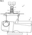
- Fig. 5 shows another embodiment of a partially shown lifting arrangement 1.
- the setup corresponds to the setup shown in Fig. 4 .
- the gyroscopic stabilization means 16 is again attached to the bunch of cables 7 connecting the hook 6 to the handling tool 10. It is attached somewhere between the hook 6 and the handling tool 10. Its resistance or reaction forces act on the bunch of cables 7 and thus stabilize the whole swinging or rotating system.
- Fig. 6 shows another embodiment of a lifting arrangement 1 shown only in part.
- the gyroscopic device 16 is directly attached to the handling tool 10. It is obvious that the stabilization device 16, which is firmly attached to the handling tool 10 can be positioned at various locations at the handling tool 10.
- Fig. 7 shows a further embodiment of a non-claimed lifting arrangement 1, which is shown only in part.
- the figure shows the hook 6 and the cables 7 connecting the hook 6 to a handling tool 10.
- the handling tool 10 is attached to a tower segment 15, which shall be installed either on the bottom at a respective foundation or which shall be attached to a previously installed tower segment 15.
- the gyroscopic stabilization device 16 is attached to the frame-like handling tool 10 for stabilizing the system.
- the stabilization device 16 can be directly attached to the bottom of this bottom segment 15.
- Fig. 8 shows another embodiment with the component 11 hanging at the hook being a hub 13.
- the gyroscopic stabilization device 16 is mounted directly on the hub 13.
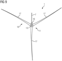
- FIG. 9 shows an embodiment of a lifting arrangement 1, which is again shown only in part.
- the component 11 which shall be lifted is a complete rotor 18 comprising three rotor blades 17 being attached to the hub 13.
- the hub 13 and thus the complete rotor 18 is attached to the lifting device 2 via a cable 7 connecting it, for example, directly to the hook 6.
- the gyroscopic stabilization device 16 is directly attached to the hub 13 stabilizes any unwanted movement of the component 11 respectively the rotor 18.
- the stabilization device 16 comprises at least one sensor means which senses any kind of movement or vibration or rotation of the respective component or the swinging or rotating system, which vibration or rotation needs to be stabilized or counteracted. Based on the sensor measurement the stabilization device 16 is controlled by means of a respective controlling device, which especially controls the tilting action and thus the counter or resistance forces produced for countering or extinguishing the respective unwanted vibrations or rotations.
Landscapes
- Engineering & Computer Science (AREA)
- Mechanical Engineering (AREA)
- Life Sciences & Earth Sciences (AREA)
- Sustainable Development (AREA)
- Sustainable Energy (AREA)
- Chemical & Material Sciences (AREA)
- Combustion & Propulsion (AREA)
- General Engineering & Computer Science (AREA)
- Wind Motors (AREA)
Claims (5)
- Procédé d'installation de composants (11) d'une éolienne, avec un dispositif de levage (2) pour soulever le composant respectif (11) suspendu au dispositif de levage (2) via au moins un câble (4, 7, 9),dans lequel au moins un dispositif de stabilisation (16) stabilise le composant (11) contre des mouvements induits par des forces externes au moyen d'un effet gyroscopique, dans lequel le dispositif de stabilisation (16) est attaché à un faisceau de câbles (7) reliant un moyen de fixation (5) du dispositif de levage (2) à un outil de manutention (10) de sorte que le dispositif de stabilisation (16) soit attaché entre le moyen de fixation (5) et l'outil de manutention (10) ; dans lequella stabilisation est assurée au moyen d'un volant rotatif qui est incliné au moyen d'un dispositif d'inclinaison autour d'au moins un axe avec une orientation perpendiculaire à l'axe de rotation du volant.
- Procédé selon la revendication 1, caractérisé en ce qu'un dispositif capteur fournit des valeurs de mesure concernant les mouvements induits par les forces avec le dispositif de stabilisation (16) commandé sur la base des valeurs de mesure.
- Procédé selon l'une des revendications précédentes,
caractérisé en ce que le composant (11) est une pale de rotor (17), une nacelle (12), un moyeu (13), une section de tour (15), un générateur ou une boîte de vitesses. - Agencement de levage pour soulever des composants lors de l'installation d'une éolienne, comprenant un dispositif de levage (2) et un composant (11) attaché au dispositif de levage (2) via au moins un câble (4, 7, 9),dans lequel au moins un dispositif de stabilisation (16) est prévu pour stabiliser le composant (11) contre des mouvements induits par des forces externes au moyen d'un effet gyroscopique, dans lequel le dispositif de stabilisation (16) est attaché à un faisceau de câbles (7) reliant un moyen de fixation (5) du dispositif de levage (2) à un outil de manutention (10) de sorte que le dispositif de stabilisation (16) soit attaché entre le moyen de fixation (5) et l'outil de manutention (10) ;dans lequel le dispositif de stabilisation (16) comprend un volant rotatif et un dispositif d'inclinaison pour incliner le volant autour d'au moins un axe avec une orientation perpendiculaire à l'axe de rotation du volant ; etdans lequel le composant (11) est une pale de rotor (17), une nacelle (12), un moyeu (13), une section de tour (15), un générateur ou une boîte de vitesses.
- Agencement de levage selon la revendication 4, caractérisé en ce qu'un dispositif capteur est prévu pour fournir des valeurs de mesure concernant les mouvements induits par les forces avec le dispositif de stabilisation (16) commandé sur la base des valeurs de mesure.
Applications Claiming Priority (2)
| Application Number | Priority Date | Filing Date | Title |
|---|---|---|---|
| DE102017206527 | 2017-04-18 | ||
| PCT/EP2017/082061 WO2018192675A1 (fr) | 2017-04-18 | 2017-12-08 | Procédé d'installation de composants d'une turbine éolienne |
Publications (2)
| Publication Number | Publication Date |
|---|---|
| EP3592973A1 EP3592973A1 (fr) | 2020-01-15 |
| EP3592973B1 true EP3592973B1 (fr) | 2023-07-26 |
Family
ID=61132370
Family Applications (1)
| Application Number | Title | Priority Date | Filing Date |
|---|---|---|---|
| EP17837862.6A Active EP3592973B1 (fr) | 2017-04-18 | 2017-12-08 | Procédé d'installation de composants d'une turbine éolienne et dispositif de levage |
Country Status (5)
| Country | Link |
|---|---|
| US (1) | US11738975B2 (fr) |
| EP (1) | EP3592973B1 (fr) |
| CN (1) | CN110506161A (fr) |
| DK (1) | DK3592973T3 (fr) |
| WO (1) | WO2018192675A1 (fr) |
Families Citing this family (6)
| Publication number | Priority date | Publication date | Assignee | Title |
|---|---|---|---|---|
| DE102019205329A1 (de) * | 2019-04-12 | 2020-10-15 | Construction Robotics GmbH | Vorrichtung zur Steuerung einer an einem Strang hängenden Last |
| EP3983329A1 (fr) * | 2019-06-11 | 2022-04-20 | Vestas Wind Systems A/S | Procédé de manipulation d'un composant d'éolienne et système de levage associé |
| BE1027530B1 (nl) * | 2019-08-29 | 2021-03-29 | Deme Offshore Be Nv | Werkwijze voor het heffen van een object vanaf een vaartuigdek |
| US11976632B2 (en) * | 2020-07-09 | 2024-05-07 | Vestas Wind Systems A/S | Mass damper module for wind turbine installation |
| US11686290B2 (en) | 2020-07-30 | 2023-06-27 | General Electric Company | Lifting device for a wind turbine rotor blade |
| EP4253302A1 (fr) | 2022-03-29 | 2023-10-04 | Siemens Gamesa Renewable Energy A/S | Procédé de levage d'une pale de rotor d'éolienne et étrier de levage |
Citations (1)
| Publication number | Priority date | Publication date | Assignee | Title |
|---|---|---|---|---|
| CN105604790A (zh) * | 2015-12-29 | 2016-05-25 | 北京天诚同创电气有限公司 | 风电机组及其稳定控制装置与方法 |
Family Cites Families (41)
| Publication number | Priority date | Publication date | Assignee | Title |
|---|---|---|---|---|
| US2916162A (en) * | 1953-11-06 | 1959-12-08 | Maschf Augsburg Nuernberg Ag | Apparatus for damping pendulum motions of the load suspended from a lifting machine |
| US3210114A (en) * | 1963-11-21 | 1965-10-05 | Lawton Lawrence | Apparatus for orienting a suspended load |
| US3524606A (en) * | 1968-03-12 | 1970-08-18 | Lawrence Mfg Co | Cable reel mounting |
| US3536298A (en) * | 1968-05-09 | 1970-10-27 | North American Rockwell | Cable handling winch |
| US3608384A (en) * | 1969-01-03 | 1971-09-28 | Skagit Corp | Apparatus for rotationally positioning a supported load |
| US3799358A (en) * | 1972-06-12 | 1974-03-26 | Zachry Co H B | Helicopter tail rotor device |
| US3874514A (en) * | 1973-01-15 | 1975-04-01 | Ray Wilson | Crane arrangement and ladle structure |
| US6327994B1 (en) * | 1984-07-19 | 2001-12-11 | Gaudencio A. Labrador | Scavenger energy converter system its new applications and its control systems |
| US4883184A (en) * | 1986-05-23 | 1989-11-28 | Albus James S | Cable arrangement and lifting platform for stabilized load lifting |
| JP2770221B2 (ja) * | 1995-04-27 | 1998-06-25 | 村田機械株式会社 | 天井走行車 |
| WO1997005052A1 (fr) * | 1995-07-28 | 1997-02-13 | Hitachi, Ltd. | Procede et dispositif de basculement d'un organe suspendu |
| US5871249A (en) * | 1996-11-12 | 1999-02-16 | Williams; John H. | Stable positioning system for suspended loads |
| JP3315357B2 (ja) * | 1997-10-16 | 2002-08-19 | 三菱重工業株式会社 | ジャイロスコープを利用した吊荷の旋回姿勢制御装置およびその制御方法 |
| US6412649B1 (en) * | 2000-02-07 | 2002-07-02 | Jon E. Khachaturian | Spreader bar apparatus |
| US6523781B2 (en) * | 2000-08-30 | 2003-02-25 | Gary Dean Ragner | Axial-mode linear wind-turbine |
| ES2206014B1 (es) * | 2002-03-26 | 2005-07-16 | Manuel Torres Martinez | Grua para montaje de aerogeneradores y proceso de montaje. |
| US6826452B1 (en) * | 2002-03-29 | 2004-11-30 | The Penn State Research Foundation | Cable array robot for material handling |
| DK2010783T3 (da) * | 2006-04-24 | 2014-08-25 | Kite Gen Res Srl | Vindsystem, der omfatter ydedygtige vingeprofiler, samt proces til at producere elektrisk energi |
| PT103489B (pt) * | 2006-05-31 | 2008-11-28 | Omnidea Lda | Sistema modular de aproveitamento de recursos atmosféricos |
| US8069634B2 (en) * | 2006-10-02 | 2011-12-06 | General Electric Company | Lifting system and apparatus for constructing and enclosing wind turbine towers |
| WO2009122754A1 (fr) * | 2008-04-05 | 2009-10-08 | Toneaki Yasunobu | Générateur de puissance |
| ITTO20080423A1 (it) * | 2008-06-04 | 2008-09-03 | Massimo Ippolito | Infrastruttura ottimizzata di manovra e di decollo assistito di profili alari per generatore eolico troposferico. |
| ITTO20090706A1 (it) * | 2009-09-16 | 2009-12-16 | Ce S I Ct Studi Ind Di Taddei Simona | Sistema di rinvio e guida antiattorcigliamento per cavi correnti. |
| US8070000B2 (en) * | 2009-10-23 | 2011-12-06 | Vestas Wind Systems A/S | Apparatus and method for assembling wind turbines |
| US9950910B2 (en) * | 2012-09-11 | 2018-04-24 | Eltronic A/S | Method for controlling the orientation of a load suspended from a bearing wire about said bearing wire and a winch arrangement |
| US8820718B2 (en) * | 2012-09-13 | 2014-09-02 | Jamey Weidner | Winch mount for all-terrain vehicle |
| JP2014131940A (ja) * | 2013-01-07 | 2014-07-17 | Ohbayashi Corp | 吊物旋回装置及び方法 |
| CN203428775U (zh) * | 2013-06-28 | 2014-02-12 | 潘存勋 | 一种吊装抗风平衡器 |
| DE102013219279A1 (de) * | 2013-09-25 | 2015-03-26 | Schaeffler Technologies Gmbh & Co. Kg | Lastbewegungsdämpfer und Hebevorrichtung für hängende Lasten |
| JP2015101413A (ja) * | 2013-11-21 | 2015-06-04 | 株式会社大林組 | 吊物旋回装置及び方法 |
| NO20131594A1 (no) * | 2013-12-02 | 2015-06-03 | Savant Tech As | Styrbar løfteramme |
| KR101607995B1 (ko) * | 2014-02-28 | 2016-03-31 | 삼성중공업 주식회사 | 리프팅 장치 |
| KR20150111415A (ko) * | 2014-03-21 | 2015-10-06 | 한국항공우주연구원 | 무게중심 조절형 리프팅 장치 |
| US9932211B2 (en) * | 2014-06-04 | 2018-04-03 | National Oilwell Varco, L.P. | Line stabilizer |
| KR101649942B1 (ko) * | 2014-07-09 | 2016-08-30 | 주식회사 포스코건설 | 자이로원리를 이용한 자이로타입 인양물 인양자세제어 시스템 및 그의 운용 방법 |
| EP3070044B1 (fr) * | 2015-03-19 | 2018-08-08 | ALSTOM Renewable Technologies | Systèmes et procédés de levage |
| JP6605840B2 (ja) | 2015-05-13 | 2019-11-13 | 鹿島建設株式会社 | 吊荷の姿勢制御装置 |
| GB201513483D0 (en) * | 2015-07-30 | 2015-09-16 | Ihc Engineering Business Ltd | Load control apparatus |
| WO2018093306A1 (fr) * | 2016-11-18 | 2018-05-24 | Saab Ab | Agencement de stabilisation pour une stabilisation d'un mât d'antenne |
| NL2017937B1 (en) * | 2016-12-06 | 2018-06-19 | Itrec Bv | A wave-induced motion compensating crane for use on an offshore vessel, vessel and load transferring method |
| EP3418555A1 (fr) * | 2017-06-20 | 2018-12-26 | General Electric Company | Ensemble de positionnement pour dispositif de levage de pale de rotor d'éolienne |
-
2017
- 2017-12-08 CN CN201780089818.7A patent/CN110506161A/zh active Pending
- 2017-12-08 DK DK17837862.6T patent/DK3592973T3/da active
- 2017-12-08 US US16/605,523 patent/US11738975B2/en active Active
- 2017-12-08 EP EP17837862.6A patent/EP3592973B1/fr active Active
- 2017-12-08 WO PCT/EP2017/082061 patent/WO2018192675A1/fr unknown
Patent Citations (1)
| Publication number | Priority date | Publication date | Assignee | Title |
|---|---|---|---|---|
| CN105604790A (zh) * | 2015-12-29 | 2016-05-25 | 北京天诚同创电气有限公司 | 风电机组及其稳定控制装置与方法 |
Also Published As
| Publication number | Publication date |
|---|---|
| CN110506161A (zh) | 2019-11-26 |
| US20200122981A1 (en) | 2020-04-23 |
| EP3592973A1 (fr) | 2020-01-15 |
| WO2018192675A1 (fr) | 2018-10-25 |
| US11738975B2 (en) | 2023-08-29 |
| DK3592973T3 (da) | 2023-08-28 |
Similar Documents
| Publication | Publication Date | Title |
|---|---|---|
| EP3592973B1 (fr) | Procédé d'installation de composants d'une turbine éolienne et dispositif de levage | |
| JP5055023B2 (ja) | 風力発電装置のロータ取付け方法および風力発電装置の建設方法 | |
| EP3814628B1 (fr) | Unité d'amortissement pour structure de tour | |
| CA2612812C (fr) | Amortisseur actif de tour | |
| JP4885073B2 (ja) | 風車回転翼の吊下げ装置、風車回転翼の取付け方法、および風力発電装置の建設方法 | |
| JP6605840B2 (ja) | 吊荷の姿勢制御装置 | |
| EP2167748B2 (fr) | Système pour amortir les oscillations dans une structure | |
| EP2650537B1 (fr) | Assemblage avec contrepoids pour équilibrer et aligner le rotor partiellement monté d'une éolienne, et méthode associée | |
| WO2013051167A1 (fr) | Dispositif et procédé de fixation et détachement d'aubes pour éolienne | |
| JP4210540B2 (ja) | ブレードのメンテナンスが容易な風車及び風力発電装置 | |
| CN108368825B (zh) | 用于将转子安装至风轮机的驱动轴的方法和系统 | |
| CN109477456B (zh) | 在维修期间具有减振的风力涡轮机系统 | |
| PT1592882E (pt) | Processo para a montagem de uma pá de rotor de uma instalação de energia eólica sem utilização de uma grua. | |
| CN105253795A (zh) | 更换风力涡轮机叶片的方法和装置 | |
| EP3431751B1 (fr) | Système et procédé pour suspendre une pale de rotor d'une tour supérieure d'éolienne | |
| US11773825B2 (en) | Assembly method and assembly system for a vibration damper of a wind power plant tower | |
| EP2067991A2 (fr) | Amortisseur actif contre les vibrations de cadres à base de générateur | |
| EP2728332B1 (fr) | Banc d'essai | |
| JP2015075037A (ja) | 風車用のブレード着脱方法及びブレード着脱装置 | |
| CN204594693U (zh) | 固体火箭发动机离心过载试验系统 | |
| JP3215594U (ja) | 吊荷姿勢制御装置 | |
| JP5824206B2 (ja) | 吊荷旋回装置 | |
| TW202037552A (zh) | 用於將起重機吊鉤連接至風力渦輪機葉片的附接工具、附接裝置及用於抬升風力渦輪機葉片的方法 | |
| CN113950458A (zh) | 用于控制悬挂在缆索上的载荷的设备 | |
| US20200124025A1 (en) | Gyro for stabilizing wind turbine movements |
Legal Events
| Date | Code | Title | Description |
|---|---|---|---|
| STAA | Information on the status of an ep patent application or granted ep patent |
Free format text: STATUS: UNKNOWN |
|
| STAA | Information on the status of an ep patent application or granted ep patent |
Free format text: STATUS: THE INTERNATIONAL PUBLICATION HAS BEEN MADE |
|
| PUAI | Public reference made under article 153(3) epc to a published international application that has entered the european phase |
Free format text: ORIGINAL CODE: 0009012 |
|
| STAA | Information on the status of an ep patent application or granted ep patent |
Free format text: STATUS: REQUEST FOR EXAMINATION WAS MADE |
|
| 17P | Request for examination filed |
Effective date: 20191009 |
|
| AK | Designated contracting states |
Kind code of ref document: A1 Designated state(s): AL AT BE BG CH CY CZ DE DK EE ES FI FR GB GR HR HU IE IS IT LI LT LU LV MC MK MT NL NO PL PT RO RS SE SI SK SM TR |
|
| STAA | Information on the status of an ep patent application or granted ep patent |
Free format text: STATUS: EXAMINATION IS IN PROGRESS |
|
| 17Q | First examination report despatched |
Effective date: 20220214 |
|
| GRAP | Despatch of communication of intention to grant a patent |
Free format text: ORIGINAL CODE: EPIDOSNIGR1 |
|
| STAA | Information on the status of an ep patent application or granted ep patent |
Free format text: STATUS: GRANT OF PATENT IS INTENDED |
|
| INTG | Intention to grant announced |
Effective date: 20230322 |
|
| GRAS | Grant fee paid |
Free format text: ORIGINAL CODE: EPIDOSNIGR3 |
|
| GRAA | (expected) grant |
Free format text: ORIGINAL CODE: 0009210 |
|
| STAA | Information on the status of an ep patent application or granted ep patent |
Free format text: STATUS: THE PATENT HAS BEEN GRANTED |
|
| AK | Designated contracting states |
Kind code of ref document: B1 Designated state(s): AL AT BE BG CH CY CZ DE DK EE ES FI FR GB GR HR HU IE IS IT LI LT LU LV MC MK MT NL NO PL PT RO RS SE SI SK SM TR |
|
| REG | Reference to a national code |
Ref country code: CH Ref legal event code: EP |
|
| REG | Reference to a national code |
Ref country code: IE Ref legal event code: FG4D |
|
| REG | Reference to a national code |
Ref country code: DE Ref legal event code: R096 Ref document number: 602017071892 Country of ref document: DE |
|
| REG | Reference to a national code |
Ref country code: DK Ref legal event code: T3 Effective date: 20230825 |
|
| REG | Reference to a national code |
Ref country code: LT Ref legal event code: MG9D |
|
| REG | Reference to a national code |
Ref country code: NL Ref legal event code: MP Effective date: 20230726 |
|
| REG | Reference to a national code |
Ref country code: AT Ref legal event code: MK05 Ref document number: 1592195 Country of ref document: AT Kind code of ref document: T Effective date: 20230726 |
|
| PG25 | Lapsed in a contracting state [announced via postgrant information from national office to epo] |
Ref country code: NL Free format text: LAPSE BECAUSE OF FAILURE TO SUBMIT A TRANSLATION OF THE DESCRIPTION OR TO PAY THE FEE WITHIN THE PRESCRIBED TIME-LIMIT Effective date: 20230726 |
|
| PG25 | Lapsed in a contracting state [announced via postgrant information from national office to epo] |
Ref country code: GR Free format text: LAPSE BECAUSE OF FAILURE TO SUBMIT A TRANSLATION OF THE DESCRIPTION OR TO PAY THE FEE WITHIN THE PRESCRIBED TIME-LIMIT Effective date: 20231027 |
|
| PGFP | Annual fee paid to national office [announced via postgrant information from national office to epo] |
Ref country code: GB Payment date: 20231220 Year of fee payment: 7 |
|
| PG25 | Lapsed in a contracting state [announced via postgrant information from national office to epo] |
Ref country code: IS Free format text: LAPSE BECAUSE OF FAILURE TO SUBMIT A TRANSLATION OF THE DESCRIPTION OR TO PAY THE FEE WITHIN THE PRESCRIBED TIME-LIMIT Effective date: 20231126 |
|
| PG25 | Lapsed in a contracting state [announced via postgrant information from national office to epo] |
Ref country code: SE Free format text: LAPSE BECAUSE OF FAILURE TO SUBMIT A TRANSLATION OF THE DESCRIPTION OR TO PAY THE FEE WITHIN THE PRESCRIBED TIME-LIMIT Effective date: 20230726 Ref country code: RS Free format text: LAPSE BECAUSE OF FAILURE TO SUBMIT A TRANSLATION OF THE DESCRIPTION OR TO PAY THE FEE WITHIN THE PRESCRIBED TIME-LIMIT Effective date: 20230726 Ref country code: PT Free format text: LAPSE BECAUSE OF FAILURE TO SUBMIT A TRANSLATION OF THE DESCRIPTION OR TO PAY THE FEE WITHIN THE PRESCRIBED TIME-LIMIT Effective date: 20231127 Ref country code: NO Free format text: LAPSE BECAUSE OF FAILURE TO SUBMIT A TRANSLATION OF THE DESCRIPTION OR TO PAY THE FEE WITHIN THE PRESCRIBED TIME-LIMIT Effective date: 20231026 Ref country code: LV Free format text: LAPSE BECAUSE OF FAILURE TO SUBMIT A TRANSLATION OF THE DESCRIPTION OR TO PAY THE FEE WITHIN THE PRESCRIBED TIME-LIMIT Effective date: 20230726 Ref country code: LT Free format text: LAPSE BECAUSE OF FAILURE TO SUBMIT A TRANSLATION OF THE DESCRIPTION OR TO PAY THE FEE WITHIN THE PRESCRIBED TIME-LIMIT Effective date: 20230726 Ref country code: IS Free format text: LAPSE BECAUSE OF FAILURE TO SUBMIT A TRANSLATION OF THE DESCRIPTION OR TO PAY THE FEE WITHIN THE PRESCRIBED TIME-LIMIT Effective date: 20231126 Ref country code: HR Free format text: LAPSE BECAUSE OF FAILURE TO SUBMIT A TRANSLATION OF THE DESCRIPTION OR TO PAY THE FEE WITHIN THE PRESCRIBED TIME-LIMIT Effective date: 20230726 Ref country code: GR Free format text: LAPSE BECAUSE OF FAILURE TO SUBMIT A TRANSLATION OF THE DESCRIPTION OR TO PAY THE FEE WITHIN THE PRESCRIBED TIME-LIMIT Effective date: 20231027 Ref country code: FI Free format text: LAPSE BECAUSE OF FAILURE TO SUBMIT A TRANSLATION OF THE DESCRIPTION OR TO PAY THE FEE WITHIN THE PRESCRIBED TIME-LIMIT Effective date: 20230726 Ref country code: AT Free format text: LAPSE BECAUSE OF FAILURE TO SUBMIT A TRANSLATION OF THE DESCRIPTION OR TO PAY THE FEE WITHIN THE PRESCRIBED TIME-LIMIT Effective date: 20230726 |
|
| PGFP | Annual fee paid to national office [announced via postgrant information from national office to epo] |
Ref country code: FR Payment date: 20231219 Year of fee payment: 7 Ref country code: DK Payment date: 20231219 Year of fee payment: 7 Ref country code: DE Payment date: 20231214 Year of fee payment: 7 |
|
| PG25 | Lapsed in a contracting state [announced via postgrant information from national office to epo] |
Ref country code: PL Free format text: LAPSE BECAUSE OF FAILURE TO SUBMIT A TRANSLATION OF THE DESCRIPTION OR TO PAY THE FEE WITHIN THE PRESCRIBED TIME-LIMIT Effective date: 20230726 |
|
| PG25 | Lapsed in a contracting state [announced via postgrant information from national office to epo] |
Ref country code: ES Free format text: LAPSE BECAUSE OF FAILURE TO SUBMIT A TRANSLATION OF THE DESCRIPTION OR TO PAY THE FEE WITHIN THE PRESCRIBED TIME-LIMIT Effective date: 20230726 |
|
| PG25 | Lapsed in a contracting state [announced via postgrant information from national office to epo] |
Ref country code: SM Free format text: LAPSE BECAUSE OF FAILURE TO SUBMIT A TRANSLATION OF THE DESCRIPTION OR TO PAY THE FEE WITHIN THE PRESCRIBED TIME-LIMIT Effective date: 20230726 Ref country code: RO Free format text: LAPSE BECAUSE OF FAILURE TO SUBMIT A TRANSLATION OF THE DESCRIPTION OR TO PAY THE FEE WITHIN THE PRESCRIBED TIME-LIMIT Effective date: 20230726 Ref country code: ES Free format text: LAPSE BECAUSE OF FAILURE TO SUBMIT A TRANSLATION OF THE DESCRIPTION OR TO PAY THE FEE WITHIN THE PRESCRIBED TIME-LIMIT Effective date: 20230726 Ref country code: EE Free format text: LAPSE BECAUSE OF FAILURE TO SUBMIT A TRANSLATION OF THE DESCRIPTION OR TO PAY THE FEE WITHIN THE PRESCRIBED TIME-LIMIT Effective date: 20230726 Ref country code: CZ Free format text: LAPSE BECAUSE OF FAILURE TO SUBMIT A TRANSLATION OF THE DESCRIPTION OR TO PAY THE FEE WITHIN THE PRESCRIBED TIME-LIMIT Effective date: 20230726 Ref country code: SK Free format text: LAPSE BECAUSE OF FAILURE TO SUBMIT A TRANSLATION OF THE DESCRIPTION OR TO PAY THE FEE WITHIN THE PRESCRIBED TIME-LIMIT Effective date: 20230726 |