EP3592909B1 - Rigoleneinheit, rigolenkörper und einsatzstück - Google Patents
Rigoleneinheit, rigolenkörper und einsatzstück Download PDFInfo
- Publication number
- EP3592909B1 EP3592909B1 EP18717225.9A EP18717225A EP3592909B1 EP 3592909 B1 EP3592909 B1 EP 3592909B1 EP 18717225 A EP18717225 A EP 18717225A EP 3592909 B1 EP3592909 B1 EP 3592909B1
- Authority
- EP
- European Patent Office
- Prior art keywords
- plug
- trenching
- unit according
- blocks
- base plate
- Prior art date
- Legal status (The legal status is an assumption and is not a legal conclusion. Google has not performed a legal analysis and makes no representation as to the accuracy of the status listed.)
- Active
Links
Images



Classifications
-
- E—FIXED CONSTRUCTIONS
- E02—HYDRAULIC ENGINEERING; FOUNDATIONS; SOIL SHIFTING
- E02B—HYDRAULIC ENGINEERING
- E02B11/00—Drainage of soil, e.g. for agricultural purposes
- E02B11/005—Drainage conduits
-
- E—FIXED CONSTRUCTIONS
- E03—WATER SUPPLY; SEWERAGE
- E03F—SEWERS; CESSPOOLS
- E03F1/00—Methods, systems, or installations for draining-off sewage or storm water
- E03F1/002—Methods, systems, or installations for draining-off sewage or storm water with disposal into the ground, e.g. via dry wells
- E03F1/005—Methods, systems, or installations for draining-off sewage or storm water with disposal into the ground, e.g. via dry wells via box-shaped elements
-
- E—FIXED CONSTRUCTIONS
- E03—WATER SUPPLY; SEWERAGE
- E03F—SEWERS; CESSPOOLS
- E03F1/00—Methods, systems, or installations for draining-off sewage or storm water
- E03F1/002—Methods, systems, or installations for draining-off sewage or storm water with disposal into the ground, e.g. via dry wells
Definitions
- the invention relates to a drainage unit with the features of the preamble of claim 1.
- a drainage unit is, for example, from DE 10 2009 044 412 A1 famous.
- trench systems have trench bodies whose boundary walls are water-permeable.
- the stability of the trench system is determined by the columns or pylons arranged inside the trench body, which connect the base plates of the trench body to one another.
- trench bodies are stacked one on top of the other in order to achieve a sufficient drainage depth. It is important that the trench bodies stacked on top of each other give the system sufficient stability overall.
- Trench units with stackable and pluggable trench bodies are also available EP 2 495 373 A2 , WO 2011/004508 A1 and U.S. 2015/017384 A1 famous.
- the invention is based on the object of specifying a trench unit that is sufficiently stable even with larger dimensions of the trench unit, i.e. with at least two trench bodies stacked one on top of the other.
- the object is achieved by a trench unit with at least two trench bodies, each of which has an upper base plate, a lower base plate and hollow columns.
- the hollow columns are arranged vertically between the base plates and form column openings in the base plates.
- the lower base plate of one trench body and the upper base plate of the other trench body rest on one another in such a way that the column openings of the two base plates lying on them are arranged concentrically.
- the trench bodies are connected by at least one insert having a bearing surface and two male profiles arranged on either side of the bearing surface and connected thereto.
- the support surface is arranged between the overlying base plates.
- the plug-in profiles are inserted into two concentrically arranged column openings in the base plates.
- the invention has the advantage that the stability of the trench unit is improved. This makes it possible to stack almost any number of trench bodies on top of one another without the risk of the trench bodies slipping relative to one another.
- the invention provides anti-slip protection so that the transverse forces acting on the trench unit are safely dissipated without the trench body slipping. It is thus possible to vary the height of the trench unit in order to increase the drainage capacity of the trench unit.
- the plug-in profiles can thus be plugged into the column openings in a form-fitting manner.
- the plug-in profiles can be designed at least partially symmetrically, in particular completely symmetrically. On the one hand, this simplifies production. On the other hand, the plug-in profiles can be used in both directions. Incorrect installation of the plug-in profile is thus practically impossible, since both sides of the insert fit into both the upper and the lower base plate.
- the plug-in profiles each have a plurality of plug-in blocks.
- the plug blocks can be oriented in different directions in order to achieve a corresponding support effect in these directions.
- the arrangement of the plug-in blocks is arbitrary, as long as the result is a plug-in profile that can be positively connected to the concentrically arranged column openings of the base plates.
- the plug blocks are preferably arranged in a cross shape. This increases the stability of the trench unit in the main load directions.
- the plug blocks can each have reinforcing ribs which are arranged in a cross shape.
- the combination with the cross-shaped plug-in blocks results in a double cross-shaped configuration, which further increases the stability of the trench unit.
- the plug-in profiles each have contact surfaces that adjoin the inside of the hollow columns to form the form-fitting connection, the contour of the contact surfaces being adapted to the contour of the inside of the hollow columns. In this way, area forces can be transmitted to the hollow columns via the inserts, which improves the application of force and thus the stability of the trench unit.
- the contour of the contact surfaces is wave-shaped. It has been shown that this achieves a particularly stable hold with a correspondingly wavy inner profile of the hollow columns.
- the bearing surface of the insert can be essentially in the form of a ring, the outside diameter of which is larger than the diameter of the column openings. This configuration has the advantage that the insert is fixed by the weight of the upper trench body.
- the plug-in blocks are preferably connected to the ring and thus fixed in the radial direction.
- the plug blocks can be connected to one another both in the radial and in the axial direction of the insert piece, which increases the stability of the insert piece.
- a plurality of inserts are connected to one another, with the position of the inserts corresponding to the position of the column openings.
- the insert piece for the trench unit with at least two trench bodies is also disclosed on its own, i.e. independently of the trench unit.
- a trench unit with a trench body is disclosed and claimed, in which a further insert piece covers at least one column opening in the upper base plate to form a continuously accessible surface.
- the above-mentioned insert piece is not provided for connecting two trench bodies, but for covering a column opening. Accordingly, the top of the insert is flat to allow unimpeded access to the top of the trench body.
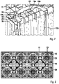
- the insert piece has only a single male profile, which is inserted into the column opening and has cross-shaped arranged male blocks, which are aligned with main ribs of the upper base plate in at least 2 mutually perpendicular directions.
- the aligned arrangement has the advantage that forces introduced into the reinforcing ribs are optimally introduced into the main ribs of the upper base plate. The same applies vice versa. The stability of the trench body is thus improved by the insert.
- the aforementioned aligned Arrangement of the plug-in blocks is also disclosed and claimed in connection with the insert for connecting two trench bodies.
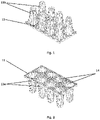
- the in the Figures 1, 2 illustrated base plates 11, 12 form the basic elements of a trench body.
- the trench body is a box-shaped body with grid-like boundary surfaces through which water can flow into the trench body.
- the trench body can be wrapped in a known manner with a geotextile in order to prevent the penetration of sediments into the trench system.
- a trench system composed of such trench bodies serves on the one hand as block storage for rainwater and on the other as block infiltration of rainwater.
- the basis of this system are the Figures 1, 2 illustrated, identical base plates, which can be combined in different ways.
- the upper base plate 11 is arranged at the top and the lower base plate 12 is arranged at the bottom.
- the base plates each have hollow columns 13a, 13b which extend perpendicularly to the base plates 11, 12 and are connected to them.
- the hollow columns 13a, 13b form spacers which determine the spacing of the base plates 11, 12 from one another.
- the hollow columns 13a, 13b are plugged onto one another with their free ends.
- the hollow columns 13a, 13b also called pylons, are cone-shaped, with the smaller cross-sectional opening forming the free end and the larger cross-sectional opening forming the end of the respective hollow column 13a, 13b connected to the respective base plate 11, 12.
- the hollow columns 13a, 13b form column openings 14 in the respective base plate 11, 12, as in FIG 2 good to see.
- trench bodies 10a, 10b In order to increase the height of the trench system, it is common for several layers of trench bodies 10a, 10b to be stacked on top of each other (see Fig. figure 5 ). A lower base plate 12 of the upper trench body 10a comes into contact with an upper base plate 11 of the underlying trench body 10b.
- an insert 15 is provided in the Figures 3, 4 is shown.
- the insert 15 has a bearing surface 16 and two plug-in profiles 17a, 17b.
- the plug-in profiles 17a, 17b are arranged on both sides of the bearing surface 16.
- the bearing surface 16 is located between the upper plug-in profile 17a and the lower plug-in profile 17b.
- the plug-in profiles 17a, 17b are designed to absorb the horizontal loads that occur in the (main) directions parallel to the base surfaces of the base bodies 11, 12.
- they have a cruciform structure with ribs which follows the corresponding ribs of the base plates 11,12.
- the bearing surface 16 extends in the circumferential direction between the plug-in profiles 17a, 17b.
- the bearing surface 16 protrudes radially beyond the plug-in profiles 17a, 17b. This makes it possible for the bearing surface 16 to rest on the upper side of the respective base plate 11, 12 and to be fixed by the weight of the upper trench body.
- the plug-in profiles 17a, 17b are symmetrical and each have a plurality of plug-in blocks 18.
- the plug-in blocks 18 serve to establish the positive connection to the hollow columns 13a, 13b or column openings 14.
- the plug-in blocks 18 each have walls 23 which delimit the plug-in blocks 18 laterally.
- the sub-blocks 18 are arranged in a cross-shape, with four sub-blocks 18 being arranged around a central sub-block 18 .
- Other arrangements of the plug blocks 18 are possible.
- the plug-in blocks 18 are essentially cuboid. Other geometries of the individual plug-in blocks 18 are possible.
- the end faces of the plug-in blocks 18, ie the free ends of the plug-in blocks 18 each have a contact surface 20 which, in the installed state, rests against the inner wall or the inside 21 of the respective hollow column 13a, 13b (see Fig figure 5 ).
- the contact surfaces 20 are formed in a wave shape. Other geometries are also possible here.
- the contact surfaces 20 advantageously extend beyond the plug-in blocks 18 so that a surface pressure in the area between the contact surfaces 20 and the inner sides 21 of the hollow columns 13a, 13b can be reduced. In this way, the horizontal forces that occur can be transferred as a surface load instead of as a line load. Larger forces can be transmitted by transferring the horizontal forces as a distributed load instead of as a line load.
- first and second reinforcing ribs 19a, 19b are arranged in a cross shape.
- the bearing surface 16 is in accordance with the embodiment Figures 3, 4 designed as a ring 22 whose outer diameter is slightly larger than the diameter of the column openings 14. This ensures that the bearing surface 16 can rest on the respective base plate 11, 12 when the insert 15 is inserted into the opening 14.
- the ring-shaped support surface 16 can have one or more recesses in order to provide guides for packaging tapes during packaging, for example on a pallet.
- the ribs of the plug-in profiles have complementary recesses or elevations in order to make it easier for several insert pieces 15 to be stacked.
- the inner diameter of the ring 22 corresponds approximately to the inner diameter of the hollow columns 13a, 13b.
- inserts 15 are combined to form a coherent composite, with the inserts 15 being connected to one another by webs.
- the composite can be mounted uniformly.
- the individual inserts 15 are elastically connected to one another in order to be able to compensate for any tolerances in the base body as such or the base body in the installation situation.
- the inserts 15 are inserted into the column openings 14, so that the plug-in profiles 17a engage with the column openings 14 or the hollow columns 13a (left-hand illustration in 6 ).
- another base plate according to the example 6 the lower base plate 12 of the upper trench body 10a on which the inserts 15 are placed.
- the column openings 14 of the two base plates 11, 12 are aligned concentrically with one another.
- the overall alignment of the two base plates 11, 12 is defined precisely and securely by the position of the inserts 15.
- This insert piece 15 is a cover in which the insert piece 15 has only a single plug-in profile 17a with plug-in blocks 18 on its underside.
- the side walls 23 of the plug-in blocks 18 are flush with the main ribs 24 of the base plate (see Fig 8 ). Specifically, the walls 23 are aligned in two mutually perpendicular directions, resulting in maximum stability in the main load directions.
- the arrangement of the walls 23 is according to both the example 7 as well as according to the example Figures 3 to 6 possible.
- the aligned arrangement is in 8 shown, in which virtual lines along the main ribs 24 are drawn.
- the result of this is that the walls 23 are aligned with the main ribs 24 in both main directions of the base plate 11 .
Landscapes
- Engineering & Computer Science (AREA)
- Life Sciences & Earth Sciences (AREA)
- Hydrology & Water Resources (AREA)
- Public Health (AREA)
- Water Supply & Treatment (AREA)
- Health & Medical Sciences (AREA)
- General Engineering & Computer Science (AREA)
- Mechanical Engineering (AREA)
- Agronomy & Crop Science (AREA)
- Civil Engineering (AREA)
- Structural Engineering (AREA)
- Sewage (AREA)
- Photovoltaic Devices (AREA)
- Mutual Connection Of Rods And Tubes (AREA)
- Conveying And Assembling Of Building Elements In Situ (AREA)
- Joining Of Building Structures In Genera (AREA)
- Floor Finish (AREA)
Description
- Die Erfindung betrifft eine Rigoleneinheit mit den Merkmalen des Oberbegriffs des Anspruchs 1. Eine derartige Rigoleneinheit ist beispielsweise aus
DE 10 2009 044 412 A1 bekannt. - Es ist bekannt, Rigolensysteme zum Entwässern von Oberflächen einzusetzen, wobei das abzuführende Wasser durch die Oberfläche in das Rigolensystem gelangt und von dort abgeführt wird, beispielsweise in eine Kläranlage. Dazu weisen Rigolensysteme Rigolenkörper auf, deren Begrenzungswände wasserdurchlässig sind. Die Stabilität der Rigolensysteme wird durch die im Inneren der Rigolenkörper angeordneten Säulen bzw. Pylonen bestimmt, die die Grundplatten des Rigolenkörpers miteinander verbinden. In der Praxis werden Rigolenkörper übereinandergestapelt, um eine ausreichende Entwässerungstiefe zu erreichen. Dabei kommt es darauf an, dass die übereinander gestapelten Rigolenkörper dem System insgesamt eine ausreichende Stabilität verleihen.
- Rigoleneinheiten mit stapelbaren und steckverbindbaren Rigolenkörpern sind außerdem aus
EP 2 495 373 A2 ,WO 2011/004508 A1 undUS 2015/017384 A1 bekannt. - Der Erfindung liegt die Aufgabe zu Grunde, eine Rigoleneinheit anzugeben, die auch bei größeren Dimensionen der Rigoleneinheit, d.h. bei wenigstens zwei übereinander gestapelten Rigolenkörpern, ausreichend stabil ist.
- Erfindungsgemäß wird diese Aufgabe durch die Rigoleneinheit nach Anspruch 1 gelöst.
- Insbesondere wird die Aufgabe durch eine Rigoleneinheit mit wenigstens zwei Rigolenkörpern gelöst, die jeweils eine obere Grundplatte, eine untere Grundplatte und Hohlsäulen aufweisen. Die Hohlsäulen sind zwischen den Grundplatten senkrecht angeordnet und bilden Säulenöffnungen in den Grundplatten. Die untere Grundplatte des einen Rigolenkörpers und die obere Grundplatte des anderen Rigolenkörpers liegen derart aufeinander auf, dass die Säulenöffnungen der beiden aufliegenden Grundplatten konzentrisch angeordnet sind. Die Rigolenkörper sind durch wenigstens ein Einsatzstück verbunden, das eine Auflagefläche und zwei Einsteckprofile aufweist, die auf beiden Seiten der Auflagefläche angeordnet und mit dieser verbunden sind. Die Auflagefläche ist zwischen den aufliegenden Grundplatten angeordnet. Die Einsteckprofile sind in zwei konzentrisch angeordnete Säulenöffnungen der aufliegenden Grundplatten eingesteckt.
- Die Erfindung hat den Vorteil, dass die Stabilität der Rigoleneinheit verbessert wird. Damit ist es möglich, eine nahezu beliebige Anzahl von Rigolenkörper an übereinander zu stapeln, ohne dass die Gefahr besteht, dass die Rigolenkörper relativ zueinander verrutschen. Die Erfindung bildet eine Verrutschsicherung, sodass die auf die Rigoleneinheit wirkenden Querkräfte sicher abgeleitet werden, ohne dass die Rigolenkörper verrutschen. Es ist damit möglich, die Höhe der Rigoleneinheit zu variieren, um die Entwässerungsleistung der Rigoleneinheit zu erhöhen.
- Bevorzugte Ausführungsformen der Erfindung sind in den Unteransprüchen angegeben.
- So können die Einsteckprofile in die Säulenöffnungen formschlüssig eingesteckt sein.
- Die Einsteckprofile können zumindest teilweise symmetrisch, insbesondere vollständig symmetrisch ausgebildet sein. Dadurch wird einerseits die Herstellung vereinfacht. Andererseits können die Einsteckprofile in beiden Richtungen verwendet werden. Ein fehlerhafter Einbau der Einsteckprofile ist damit praktisch ausgeschlossen, da beide Seiten des Einsatzstückes sowohl in die obere als auch in die untere Grundplatte passen.
- Bei einer bevorzugten Ausführungsform weisen die Einsteckprofile jeweils mehrere Steckblöcke auf. Die Steckblöcke können in unterschiedlichen Richtungen orientiert sein, um eine entsprechende Stützwirkung in diesen Richtungen zu erzielen. Die Anordnung der Steckblöcke ist beliebig, solange sich ein Einsteckprofil ergibt, das formschlüssig mit den konzentrisch angeordneten Säulenöffnungen der aufliegenden Grundplatten verbunden werden kann.
- Vorzugsweise sind die Steckblöcke kreuzförmig angeordnet. Damit wird die Stabilität der Rigoleneinheit in den Hauptbelastungsrichtungen erhöht.
- Die Steckblöcke können jeweils Verstärkungsrippen aufweisen, die kreuzförmig angeordnet sind. Durch die Kombination mit den kreuzförmig angeordneten Steckblöcken ergibt sich eine doppelt kreuzförmige Konfiguration, wodurch die Stabilität der Rigoleneinheit weiter erhöht wird.
- Bei einer bevorzugten Ausführung weisen die Einsteckprofile jeweils Anlageflächen auf, die an die Innenseite der Hohlsäulen zur Bildung der formschlüssigen Verbindung angrenzen, wobei die Kontur der Anlageflächen an die Kontur der Innenseite der Hohlsäulen angepasst ist. Auf diese Weise können über die Einsatzstücke Flächenkräfte auf die Hohlsäulen übertragen werden, wodurch die Krafteinleitung und damit die Stabilität der Rigoleneinheit verbessert wird.
- Vorzugsweise ist die Kontur der Anlageflächen wellenförmig ausgebildet. Es hat sich gezeigt, dass dadurch ein besonders stabiler Halt bei entsprechend wellenförmigen Innenprofil der Hohlsäulen erreicht wird.
- Die Auflagefläche des Einsatzstückes kann im Wesentlichen in der Form eines Ringes ausgebildet sein, dessen Außendurchmesser größer als der Durchmesser der Säulenöffnungen ist. Diese Ausgestaltung hat den Vorteil, dass das Einsatzstück durch die Gewichtskraft des oberen Rigolenkörper fixiert wird.
- Vorzugsweise sind die Steckblöcke mit dem Ring verbunden und damit in radialer Richtung fixiert. Zusätzlich können die Steckblöcke miteinander verbunden sein und zwar sowohl in radialer als auch in axialer Richtung des Einsatzstückes, wodurch die Stabilität des Einsatzstückes erhöht wird.
- Bei einer weiteren bevorzugten Ausführung sind mehrere Einsatzstücke miteinander verbunden, wobei die Position der Einsatzstücke der Lage der Säulenöffnungen entspricht. Diese Ausführung verbessert die Handhabbarkeit der Einsatzstücke, weil mehrere Einzelstücke gleichzeitig mit verschiedenen Säulenöffnungen verbunden werden können. Es ist also nicht notwendig, die einzelnen Einsatzstücke auszurichten und mit einzelnen Säulenöffnungen gesondert zu verbinden.
- Im Rahmen der Erfindung wird das Einsatzstück für die Rigoleneinheit mit wenigstens zwei Rigolenkörper auch für sich genommen, d.h. unabhängig von der Rigoleneinheit offenbart. Außerdem wird im Rahmen einer bevorzugten Ausführungsform der Erfindung eine Rigoleneinheit mit einem Rigolenkörper offenbart und beansprucht, bei dem ein weiteres Einsatzstück wenigstens eine Säulenöffnung in der oberen Grundplatte zur Bildung einer durchgängig begehbaren Fläche abdeckt.
- Im Unterschied zur dem Einsatzstück mit den auf beiden Seiten der Auflagefläche angeordneten Einsteckprofile ist das vorstehend genannte Einsatzstück nicht zum Verbinden zweier Rigolenkörper vorgesehen, sondern zum Abdecken einer Säulenöffnung. Dementsprechend ist die Oberseite des Einsatzstückes flach, um eine ungehinderte Begehung der Oberseite des Rigolenkörper zu ermöglichen. Dazu weist das Einsatzstück nur ein einziges Einsteckprofil auf, das in die Säulenöffnung eingesteckt ist und kreuzförmig angeordnete Steckblöcke aufweist, die mit Hauptrippen der oberen Grundplatte in wenigstens 2 senkrecht zu einander verlaufenden Richtungen fluchten.
- Die fluchtende Anordnung hat den Vorteil, dass in die Verstärkungsrippen eingeleitete Kräfte optimal in die Hauptrippen der oberen Grundplatte eingeleitet werden. Umgekehrt gilt dasselbe. Damit wird die Stabilität des Rigolenkörpers durch das Einsatzstück verbessert. Die vorstehend genannte fluchtende Anordnung der Steckblöcke wird auch im Zusammenhang mit dem Einsatzstück zur Verbindung zweier Rigolenkörper offenbart und beansprucht.
- Die Erfindung wird nachfolgend anhand von Ausführungsbeispielen unter Bezug auf die beigefügten Figuren mit weiteren Einzelheiten näher erläutert.
- In diesen zeigen
- Fig. 1
- eine perspektivische Ansicht einer unteren Grundplatte für einen Rigolenkörper mit mehreren Hohlsäulen;
- Fig. 2
- eine perspektivische Ansicht einer oberen Grundplatte für einen Rigolenkörper mit mehreren Hohlsäulen, die mit der Grundplatte gemäß
Fig. 1 zu einem Rigolenkörper verbindbar ist; - Fig. 3
- eine perspektivische Ansicht mehrerer Einsatzstücke, die zur Verbindung mehrerer, insbesondere zweier Rigolenkörper verwendet wird;
- Fig. 4
- eine Draufsicht auf ein Einsatzstück gemäß
Fig. 3 ; - Fig. 5
- einen Querschnitt durch zwei Rigolenkörper, die an den Grundplatten durch ein Einsatzstück verbunden sind;
- Fig. 6
- die Rigolenkörper nach
Figuren 1, 2 und die Einsatzstücke nachFigur 3 beim Verbinden der Grundplatten; - Fig. 7
- einen Schnitt durch die obere Grundplatte mit nur einem einzigen Einsteckprofil zum Abdecken der Säulenöffnung; und
- Fig. 8
- eine Draufsicht auf die obere Grundplatte eines Rigolenkörper aus mit mehreren Einsatzstücken, bei denen die ein Steckblöcke und die Hauptrippen der Grundplatte fluchten.
- In der nachfolgenden Beschreibung werden für gleiche und gleichwirkende Teile dieselben Bezugszeichen verwendet.
- Die in den
Figuren 1, 2 dargestellten Grundplatten 11, 12 bilden die Basiselemente eines Rigolenkörpers. Bei dem Rigolenkörper handelt es sich um einen kastenförmigen Körper mit gitterartigen Begrenzungsflächen, durch die Wasser in den Rigolenkörper fließen kann. Der Rigolenkörper kann in bekannter Weise mit einem Geotextil umwickelt werden, um das Eindringen von Sedimenten in das Rigolensystem zu verhindern. - Ein aus derartigen Rigolenkörpern zusammengesetztes Rigolensystem dient zum einen als Blockspeicher für Niederschlagswasser und zum anderen als Blockversickerung von Niederschlagswasser. Die Basis dieses Systems sind die
Figuren 1, 2 dargestellten, identischen Grundplatten, die auf unterschiedliche Weise miteinander kombiniert werden können. Die obere Grundplatte 11 ist im verlegten Zustand des Rigolensystems oben und die untere Grundplatte 12 unten angeordnet. Die Grundplatten weisen jeweils Hohlsäulen 13a, 13b auf, die sich senkrecht zu den Grundplatten 11, 12 erstrecken und mit diesen verbunden sind. Die Hohlsäulen 13a, 13b bilden Abstandshalter, die den Abstand der Grundplatten 11, 12 zueinander festlegen. Dazu werden die Hohlsäulen 13a, 13b mit ihren freien Enden aufeinander aufgesteckt. Die Hohlsäulen 13a, 13b, auch Pylonen genannt, sind konusartig ausgebildet, wobei die kleinere Querschnittsöffnung das freie Ende und die größere Querschnittsöffnung das mit der jeweiligen Grundplatte 11, 12 verbundene Ende der jeweiligen Hohlsäule 13a, 13b bilden. Die Hohlsäulen 13a, 13b bilden Säulenöffnungen 14 in der jeweiligen Grundplatte 11, 12, wie inFig. 2 gut zu sehen. - Um die Höhe des Rigolensystem zur vergrößern, ist es üblich, dass mehrere Lagen aus Rigolenkörpern 10a, 10b an aufeinander gestapelt werden (s.
Fig. 5 ). Dabei kommt eine untere Grundplatte 12 des oberen Rigolenkörpers 10a mit einer oberen Grundplatte 11 des darunterliegenden Rigolenkörpers 10b in Anlage. - An dieser Stelle setzt die Erfindung ein, die, wie anhand des Ausführungsbeispiels gemäß
Fig. 3 gezeigt, die Verbindung zwischen den übereinandergestapelten Rigolenkörpern 10a, 10b verbessert. - Dazu ist ein Einsatzstück 15 vorgesehen, das in den
Figuren 3, 4 dargestellt ist. Das Einsatzstück 15 weist eine Auflagefläche 16 und zwei Einsteckprofile 17a, 17b auf. Wie in denFiguren 3 und5 gut zu erkennen, sind die Einsteckprofile 17a, 17b auf beiden Seiten der Auflagefläche 16 angeordnet. Mit anderen Worten befindet sich die Auflagefläche 16 zwischen dem oberen Einsteckprofil 17a und dem unteren Einsteckprofil 17b. Die Einsteckprofile 17a, 17b sind dazu ausgebildet, die auftretenden Horizontallasten in den (Haupt)richtungen parallel zu den Grundflächen der Grundkörpern 11, 12 aufzunehmen. Dazu weisen sie eine kreuzförmige Struktur mit Rippen auf, die den entsprechenden Rippen der Grundplatten 11, 12 folgt. Die Auflagefläche 16 erstreckt sich in Umfangsrichtung zwischen den Einsteckprofilen 17a, 17b. Außerdem ragt die Auflagefläche 16 radial über die Einsteckprofile 17a, 17b vor. Dadurch ist es möglich, dass die Auflagefläche 16 auf der Oberseite der jeweiligen Grundplatte 11, 12 aufliegt und die durch den oberen Rigolenkörper durch dessen Gewicht fixiert wird. - Die Einsteckprofile 17a, 17b sind symmetrisch ausgebildet und weisen jeweils mehrere Steckblöcke 18 auf. Die Steckblöcke 18 dienen dazu, die formschlüssige Verbindung zu den Hohlsäulen 13a, 13b bzw. Säulenöffnungen 14 herzustellen. Die Steckblöcke 18 weisen jeweils Wände 23 auf, die die Steckblöcke 18 seitlich begrenzen. Wie in
Fig. 4 dargestellt, sind die Steckblöcke 18 kreuzförmig angeordnet, wobei vier Steckblöcke 18 um einen mittigen Steckblock 18 herum angeordnet sind. Andere Anordnungen der Steckblöcke 18 sind möglich. Die Steckblöcke 18 sind im wesentlichen quaderförmig ausgebildet. Andere Geometrie der einzelnen Steckblöcke 18 sind möglich. - Die Stirnflächen der Steckblöcke 18, d.h. die freien Enden der Steckblöcke 18 weisen jeweils eine Anlagefläche 20 auf, die im eingebauten Zustand an der Innenwand bzw. an der Innenseite 21 der jeweiligen Hohlsäule 13a, 13b anliegt (siehe
Fig. 5 ). Konkret sind die Anlageflächen 20 wellenförmig ausgebildet. Auch hier sind andere Geometrie möglich. Vorteilhafterweise erstrecken sich die Anlageflächen 20 über die Steckblöcke 18 hinaus, damit eine Flächenpressung im Bereich zwischen den Anlageflächen 20 und der Innenseiten 21 der Hohlsäulen 13a, 13b verringert werden kann. Auf diese Weise können die auftretenden Horizontalkräfte als Flächenlast anstatt als Linienlast übertragen werden. Durch die Übergabe der horiziontalen Kräfte als Flächenlast anstatt als Linienlast können größere Kräfte übertragen werden. - Zwischen den Wänden 23 der Steckblöcke 18 sind erste und zweite Verstärkungsrippen 19a, 19b kreuzförmig angeordnet.
- Die Auflagefläche 16 ist bei dem Ausführungsbeispiel gemäß
Figuren 3, 4 als Ring 22 ausgebildet, dessen Außendurchmesser etwas größer ist als der Durchmesser der Säulenöffnungen 14. Dadurch wird erreicht, dass die Auflagefläche 16 auf der jeweiligen Grundplatte 11, 12 aufliegen kann, wenn das Einsatzstück 15 in die Öffnung 14 eingesteckt ist. Die ringförmige Auflagefläche 16 kann eine oder mehrere Ausnehmungen aufweisen, um beim Verpacken, z.B. auf einer Pallette, Führungen für Verpackungsbänder bereitzustellen. Die Rippen der Einsteckprofile weisen komplementäre Ausnehmungen bzw Erhöhungen auf, um eine vereinfachte Stapelbarkeit mehrerer Einsatzstücke 15 zu ermöglichen. - Der Innendurchmesser des Rings 22 entspricht in etwa dem Innendurchmesser der Hohlsäulen 13a, 13b.
- Wie in
Fig. 3 gezeigt, sind vier identische Einsatzstücke 15 zu einem zusammenhängenden Verbund zusammengefasst, wobei die Einsatzstücke 15 durch Stege miteinander verbunden sind. Der Verbund kann einheitlich montiert werden. Die einzelnen Einsatzstücke 15 sind dabei elastisch miteinander verbunden, um eventuelle Toleranzen der Grundkörper als solche bzw. der Grundkörper in der Einbausituation ausgleichen zu können. - In
Fig. 5 ist gut zu erkennen, dass die untere Grundplatte 12 des oberen Rigolenkörpers 10a mit der oberen Grundplatte 11 des unteren Rigolenkörper 10b verbunden ist. Die Verbindung erfolgt durch das vorstehend beschriebene Einsatzstück 15, das in der Säulenöffnung 14 angeordnet ist. Dabei liegt die Anlagefläche 20 des Steckblocks 18 an der Innenwand 21 der unteren Hohlsäule 13b an. Die beiden Grundplatten 11, 12 sind lagefixiert und können aufgrund des Einsatzstücks 15 nicht verrutschen. Über die Höhe des Einsatzstücks 15 kann der Eingriffsgrad mit den jeweiligen Hohlsäulen 13a, 13b variiert werden, wobei bei zunehmender Höhe der Konizität der Hohlsäulen 13a, 13b Rechnung zu tragen ist. - Wie in
Fig. 6 dargestellt, werden vor dem Verbinden der Rigolenkörper die Einsatzstücke 15 in die Säulenöffnungen 14 eingesteckt, sodass die Einsteckprofile 17a mit den Säulenöffnungen 14 bzw. den Hohlsäulen 13a in Eingriff kommen (linke Darstellung inFig. 6 ). Dann wird eine weitere Grundplatte, im Beispiel gemäßFig. 6 die untere Grundplatte 12 des oberen Rigolenkörpers 10a auf die die Einsatzstücke 15 aufgesetzt. Dazu werden die Säulenöffnungen 14 der beiden Grundplatten 11, 12 konzentrisch zueinander ausgerichtet. Die Gesamtausrichtung der beiden Grundplatten 11, 12 wird durch die Lage der Einsatzstücke 15 präzise und sicher festgelegt. - In
Fig. 7 ist eine Alternative zur dem als Verbindungsstück fungierenden Einsatzstück 15 dargestellt. Bei diesem Einsatzstück 15 handelt es sich um eine Abdeckung, bei der das Einsatzstück 15 nur ein einziges Einsteckprofil 17a mit Steckblöcken 18 auf dessen Unterseite aufweist. Die Seitenwände 23 der Steckblöcke 18 fluchten mit den Hauptrippen 24 der Grundplatte (sieheFig. 8 ). Konkret fluchten die Wände 23 in zwei senkrecht zueinander verlaufenden Richtungen, sodass sich eine maximale Stabilität in den Hauptbelastungsrichtungen ergibt. Die Anordnung der Wände 23 ist sowohl bei dem Beispiel gemäßFig. 7 als auch bei dem Beispiel gemäßFiguren 3 bis 6 möglich. - Die fluchtende Anordnung ist in
Fig. 8 dargestellt, in die virtuelle Linien entlang der Hauptrippen 24 eingezeichnet sind. Daraus ergibt sich, dass die Wände 23 mit den Hauptrippen 24 in beiden Hauptrichtungen der Grundplatte 11 fluchten. -
- 10a
- erster Rigolenkörper
- 10b
- zweiter Rigolenkörper
- 11
- obere Grundplatte
- 12
- untere Grundplatte
- 13a
- obere Hohlsäule
- 13b
- untere Hohlsäule
- 14
- Säulenöffnungen
- 15
- Einsatzstück
- 16
- Auflagefläche
- 17a
- oberes Einsteckprofil
- 17b
- unteres Einsteckprofil
- 18
- Steckblöcke
- 19a
- erste Verstärkungsrippen
- 19b
- zweite Verstärkungsrippen
- 20
- Anlageflächen
- 21
- Innenseite der Hohlsäule
- 22
- Ring
- 23
- Seitenwände der Steckblöcke
- 24
- Hauptrippen
Claims (14)
- Rigoleneinheit mit wenigstens zwei Rigolenkörpern (10a, 10b), die jeweils eine obere Grundplatte (11), eine untere Grundplatte (12) und Hohlsäulen (13a, 13b) aufweisen, die zwischen den Grundplatten (11, 12) senkrecht angeordnet sind und Säulenöffnungen (14) in den Grundplatten (11, 12) bilden, wobei die untere Grundplatte (11) des einen Rigolenkörpers (10a) und die obere Grundplatte (12) des anderen Rigolenkörpers (10b) derart aufeinander aufliegen, dass die Säulenöffnungen (14) der beiden aufliegenden Grundplatten (11, 12) konzentrisch angeordnet sind,wobei die Rigolenkörper (10a, 10b) durch wenigstens ein Einsatzstück (15) verbunden sind, das eine Auflagefläche (16) und zwei Einsteckprofile (17a, 17b) aufweist, die auf beiden Seiten der Auflagefläche (16) angeordnet und mit dieser verbunden sind, wobei die Auflagefläche (16) zwischen den aufliegenden Grundplatten (11, 12) angeordnet istdadurch gekennzeichnet ist, dassdie Einsteckprofile (17a, 17b) in zwei konzentrisch angeordnete Säulenöffnungen (14) der aufliegenden Grundplatten (11, 12) eingesteckt sind.
- Rigoleneinheit nach Anspruch 1,
dadurch gekennzeichnet, dass
die Einsteckprofile (17a, 17b) in die Säulenöffnungen (14) formschlüssig eingesteckt sind. - Rigoleneinheit nach Anspruch 1 oder 2,
dadurch gekennzeichnet, dass
die Einsteckprofile (17a, 17b) zumindest teilweise symmetrisch ausgebildet sind. - Rigoleneinheit nach einem der vorhergehenden Ansprüche,
dadurch gekennzeichnet, dass
die Einsteckprofile (17a, 17b) jeweils mehrere Steckblöcke (18) aufweisen. - Rigoleneinheit nach Anspruch 4,
dadurch gekennzeichnet, dass
die Steckblöcke (18) kreuzförmig angeordnet sind. - Rigoleneinheit nach Anspruch 4 oder 5,
dadurch gekennzeichnet, dass
die Steckblöcke (18) jeweils Verstärkungsrippen (19a, 19b) aufweisen, die kreuzförmig angeordnet sind. - Rigoleneinheit nach einem der vorhergehenden Ansprüche,
dadurch gekennzeichnet, dass
die Einsteckprofile (17a, 17b) jeweils Anlageflächen (20) aufweisen, die an die Innenseite (21) der Hohlsäulen zur Bildung der formschlüssigen Verbindung angrenzen, wobei die Kontur der Anlageflächen (20) an die Kontur der Innenseite (21) der Hohlsäulen (13a, 13b) angepasst ist. - Rigoleneinheit nach Anspruch 7,
dadurch gekennzeichnet, dass
die Kontur der Anlageflächen (20) wellenförmig ausgebildet ist. - Rigoleneinheit nach einem der vorhergehenden Ansprüche,
dadurch gekennzeichnet, dass
die Auflagefläche (16) des Einsatzstückes (15) im Wesentlichen in der Form eines Ringes (22) ausgebildet ist, dessen Außendurchmesser größer als der Durchmesser der Säulenöffnungen (14) ist. - Rigoleneinheit nach Anspruch 9,
dadurch gekennzeichnet, dass
die Steckblöcke (18) mit dem Ring (22) verbunden sind. - Rigoleneinheit nach einem der Ansprüche 4 bis 10,
dadurch gekennzeichnet, dass
die Steckblöcke (18) miteinander verbunden sind. - Rigoleneinheit nach einem der Ansprüche 4 bis 11,
dadurch gekennzeichnet, dass
die kreuzförmig angeordneten Steckblöcke (18) mit Hauptrippen der oberen Grundplatte (12) in wenigstens zwei senkrecht zueinander verlaufenden Richtungen fluchten. - Rigoleneinheit nach einem der vorhergehenden Ansprüche,
dadurch gekennzeichnet, dass
mehrere Einsatzstücke (15) miteinander verbunden sind, wobei die Position der Einsatzstücke (15) der Lage der Säulenöffnungen (14) entspricht. - Rigoleneinheit nach einem der vorhergehenden Ansprüche,
dadurch gekennzeichnet, dass
ein weiteres Einsatzstück (15) wenigstens eine Säulenöffnung (14) in einer oberen Grundplatte (12) eines Rigolenkörpers (10a) zur Bildung einer begehbaren Fläche abdeckt und ein einziges Einsteckprofil (17a) aufweist, das in die Säulenöffnung (14) eingesteckt ist und kreuzförmig angeordnete Steckblöcke (18) aufweist, die mit Hauptrippen der oberen Grundplatte (12) in wenigstens zwei senkrecht zueinander verlaufenden Richtungen fluchten.
Applications Claiming Priority (2)
| Application Number | Priority Date | Filing Date | Title |
|---|---|---|---|
| DE102017105002.7A DE102017105002A1 (de) | 2017-03-09 | 2017-03-09 | Rigoleneinheit, Rigolenkörper und Einsatzstück |
| PCT/EP2018/055557 WO2018162530A2 (de) | 2017-03-09 | 2018-03-07 | Rigoleneinheit, rigolenkörper und einsatzstück |
Publications (2)
| Publication Number | Publication Date |
|---|---|
| EP3592909A2 EP3592909A2 (de) | 2020-01-15 |
| EP3592909B1 true EP3592909B1 (de) | 2023-01-04 |
Family
ID=61965908
Family Applications (1)
| Application Number | Title | Priority Date | Filing Date |
|---|---|---|---|
| EP18717225.9A Active EP3592909B1 (de) | 2017-03-09 | 2018-03-07 | Rigoleneinheit, rigolenkörper und einsatzstück |
Country Status (8)
| Country | Link |
|---|---|
| US (1) | US10808391B2 (de) |
| EP (1) | EP3592909B1 (de) |
| CN (1) | CN110382795A (de) |
| AU (1) | AU2018229753B2 (de) |
| DE (1) | DE102017105002A1 (de) |
| EA (1) | EA201992085A1 (de) |
| PL (1) | PL3592909T3 (de) |
| WO (1) | WO2018162530A2 (de) |
Families Citing this family (4)
| Publication number | Priority date | Publication date | Assignee | Title |
|---|---|---|---|---|
| US11492793B2 (en) * | 2019-03-08 | 2022-11-08 | Brentwood Industries, Inc. | Storm water drain tank and assembly |
| EP4413209A1 (de) | 2021-10-07 | 2024-08-14 | Advanced Drainage Systems, Inc. | Kastenanordnung zur verwaltung von regenwasser |
| US20230243143A1 (en) * | 2021-10-07 | 2023-08-03 | Advanced Drainage Systems, Inc | Stormwater management crate assembly with tapered columns |
| CR20240259A (es) | 2021-12-30 | 2024-08-19 | Advanced Drainage Syst | Caja de aguas pluviales con soportes |
Family Cites Families (13)
| Publication number | Priority date | Publication date | Assignee | Title |
|---|---|---|---|---|
| EP1416099B1 (de) | 2002-10-31 | 2008-09-17 | Polypipe Civils Limited | Grundwasserdrainagesystem |
| CA2576600C (en) * | 2006-02-08 | 2010-05-11 | Brentwood Industries, Inc. | Water drain tank or channel module |
| JP4444366B1 (ja) * | 2009-07-08 | 2010-03-31 | 古河電気工業株式会社 | 水貯留施設、水貯留施設の施工方法、水貯留施設の水平方向耐荷重向上方法および骨格ブロックの水平方向ずれ防止方法 |
| DE102009044412A1 (de) | 2009-10-05 | 2011-04-07 | Aco Severin Ahlmann Gmbh & Co. Kg | Rigolenkörper |
| DE102010045001A1 (de) * | 2010-09-10 | 2012-03-15 | Auer Packaging Gmbh | Entwässerungssystem, Verfahren zu seiner Herstellung und Bauelemente hierfür |
| DE202010016295U1 (de) * | 2010-12-07 | 2012-03-12 | Rehau Ag + Co | Strukturkörper für ein Rigolensystem und Rigolensystem |
| DE102012100555B4 (de) * | 2012-01-24 | 2017-11-09 | Aco Severin Ahlmann Gmbh & Co. Kg | Deckelelement |
| DE102012100552B4 (de) * | 2012-01-24 | 2015-12-31 | Aco Severin Ahlmann Gmbh & Co. Kg | Rigolenkörperflächeneinheit |
| DE102012100560A1 (de) | 2012-01-24 | 2013-07-25 | Aco Severin Ahlmann Gmbh & Co. Kg | Rigolenkörper-Verbindungselement |
| DK2980328T3 (da) * | 2014-08-01 | 2020-04-06 | Otto Graf Gmbh Kunststofferzeugnisse | Nedsivningsblokelement, nedsivningsblok og transportenhed |
| CN104790463A (zh) * | 2015-03-27 | 2015-07-22 | 苏州汇邦环保科技有限公司 | 组合式雨水收集模块 |
| CN304206586S (de) | 2016-08-30 | 2017-07-18 | ||
| CN304151996S (de) | 2016-08-30 | 2017-05-31 |
-
2017
- 2017-03-09 DE DE102017105002.7A patent/DE102017105002A1/de not_active Withdrawn
-
2018
- 2018-03-07 US US16/491,309 patent/US10808391B2/en active Active
- 2018-03-07 PL PL18717225.9T patent/PL3592909T3/pl unknown
- 2018-03-07 EA EA201992085A patent/EA201992085A1/ru unknown
- 2018-03-07 WO PCT/EP2018/055557 patent/WO2018162530A2/de not_active Ceased
- 2018-03-07 AU AU2018229753A patent/AU2018229753B2/en active Active
- 2018-03-07 EP EP18717225.9A patent/EP3592909B1/de active Active
- 2018-03-07 CN CN201880016113.7A patent/CN110382795A/zh active Pending
Also Published As
| Publication number | Publication date |
|---|---|
| DE102017105002A1 (de) | 2018-09-13 |
| US10808391B2 (en) | 2020-10-20 |
| US20200056361A1 (en) | 2020-02-20 |
| WO2018162530A3 (de) | 2018-11-29 |
| EP3592909A2 (de) | 2020-01-15 |
| AU2018229753B2 (en) | 2021-02-18 |
| PL3592909T3 (pl) | 2023-05-08 |
| AU2018229753A1 (en) | 2019-09-26 |
| WO2018162530A2 (de) | 2018-09-13 |
| CN110382795A (zh) | 2019-10-25 |
| EA201992085A1 (ru) | 2020-02-28 |
Similar Documents
| Publication | Publication Date | Title |
|---|---|---|
| EP2980328B1 (de) | Sickerblockelement, Sickerblock und Transporteinheit | |
| EP2470722B1 (de) | Rigolenkörper | |
| EP2463449B1 (de) | Strukturkörper für ein Rigolensystem und Rigolensystem | |
| EP2592194B1 (de) | Rigoleneinheit und aus derartigen Rigoleneinheiten gebildete Transporteinheit | |
| DE602005002871T2 (de) | Versickerungsblock | |
| EP3592908B1 (de) | Rigolenkörper und mittelplatte | |
| EP3592909A2 (de) | Rigoleneinheit, rigolenkörper und einsatzstück | |
| EP2495373A2 (de) | Entwässerungssystem, Verfahren zu seiner Herstellung und Bauelemente hierfür | |
| EP2904162B1 (de) | Entwässerungsrinne mit einem rinnenkörper und einer abdeckung | |
| DE2406106A1 (de) | Isolatoranordnung mit einer die belastung verteilenden traganordnung | |
| DE202008003464U1 (de) | Höhenverstellbare Bodenstütze | |
| WO2011060476A1 (de) | Versickerungsmodul sowie damit gebildetes versickerungssystem | |
| EP3830340B1 (de) | Pflaster mit verbundsystem | |
| EP2148016B1 (de) | Rigolen-Anordnung | |
| DE102011011647A1 (de) | Hochwasserschutzsystem | |
| DE102023126945A1 (de) | Adaptervorrichtung, System und Adapterset | |
| DE202017106750U1 (de) | Vorrichtung zur Bildung von befahrbaren, zu Entwässerungs- und/oder Wasserspeicherzwecken ins Erdreich eingebrachten Hohlräumen | |
| EP1715100B1 (de) | Verlegeplatte | |
| DE19940911C1 (de) | Baumrostsystem | |
| AT512708B1 (de) | Anschlagvorrichtung für eine Absturzsicherung | |
| DE3439777A1 (de) | Kochplatten-stapelvorrichtung | |
| DE102023004452A1 (de) | Betonpflasterstein | |
| DE102011107689B4 (de) | Einbaukörper | |
| DE102023102542A1 (de) | Verbindungsplatte zur Verbindung von zwei Entwässerungsrinnen, Entwässerungsrinne und Rinnensystem | |
| DE29704557U1 (de) | Tablar o.dgl. Tragmittel |
Legal Events
| Date | Code | Title | Description |
|---|---|---|---|
| STAA | Information on the status of an ep patent application or granted ep patent |
Free format text: STATUS: UNKNOWN |
|
| STAA | Information on the status of an ep patent application or granted ep patent |
Free format text: STATUS: THE INTERNATIONAL PUBLICATION HAS BEEN MADE |
|
| PUAI | Public reference made under article 153(3) epc to a published international application that has entered the european phase |
Free format text: ORIGINAL CODE: 0009012 |
|
| STAA | Information on the status of an ep patent application or granted ep patent |
Free format text: STATUS: REQUEST FOR EXAMINATION WAS MADE |
|
| 17P | Request for examination filed |
Effective date: 20190925 |
|
| AK | Designated contracting states |
Kind code of ref document: A2 Designated state(s): AL AT BE BG CH CY CZ DE DK EE ES FI FR GB GR HR HU IE IS IT LI LT LU LV MC MK MT NL NO PL PT RO RS SE SI SK SM TR |
|
| AX | Request for extension of the european patent |
Extension state: BA ME |
|
| DAV | Request for validation of the european patent (deleted) | ||
| DAX | Request for extension of the european patent (deleted) | ||
| STAA | Information on the status of an ep patent application or granted ep patent |
Free format text: STATUS: EXAMINATION IS IN PROGRESS |
|
| 17Q | First examination report despatched |
Effective date: 20210223 |
|
| GRAP | Despatch of communication of intention to grant a patent |
Free format text: ORIGINAL CODE: EPIDOSNIGR1 |
|
| STAA | Information on the status of an ep patent application or granted ep patent |
Free format text: STATUS: GRANT OF PATENT IS INTENDED |
|
| INTG | Intention to grant announced |
Effective date: 20211111 |
|
| RAP3 | Party data changed (applicant data changed or rights of an application transferred) |
Owner name: ACO AHLMANN SE & CO. KG |
|
| GRAJ | Information related to disapproval of communication of intention to grant by the applicant or resumption of examination proceedings by the epo deleted |
Free format text: ORIGINAL CODE: EPIDOSDIGR1 |
|
| STAA | Information on the status of an ep patent application or granted ep patent |
Free format text: STATUS: EXAMINATION IS IN PROGRESS |
|
| INTC | Intention to grant announced (deleted) | ||
| GRAP | Despatch of communication of intention to grant a patent |
Free format text: ORIGINAL CODE: EPIDOSNIGR1 |
|
| STAA | Information on the status of an ep patent application or granted ep patent |
Free format text: STATUS: GRANT OF PATENT IS INTENDED |
|
| INTG | Intention to grant announced |
Effective date: 20220504 |
|
| GRAS | Grant fee paid |
Free format text: ORIGINAL CODE: EPIDOSNIGR3 |
|
| GRAJ | Information related to disapproval of communication of intention to grant by the applicant or resumption of examination proceedings by the epo deleted |
Free format text: ORIGINAL CODE: EPIDOSDIGR1 |
|
| GRAL | Information related to payment of fee for publishing/printing deleted |
Free format text: ORIGINAL CODE: EPIDOSDIGR3 |
|
| STAA | Information on the status of an ep patent application or granted ep patent |
Free format text: STATUS: EXAMINATION IS IN PROGRESS |
|
| INTC | Intention to grant announced (deleted) | ||
| GRAP | Despatch of communication of intention to grant a patent |
Free format text: ORIGINAL CODE: EPIDOSNIGR1 |
|
| STAA | Information on the status of an ep patent application or granted ep patent |
Free format text: STATUS: GRANT OF PATENT IS INTENDED |
|
| INTG | Intention to grant announced |
Effective date: 20221031 |
|
| GRAA | (expected) grant |
Free format text: ORIGINAL CODE: 0009210 |
|
| STAA | Information on the status of an ep patent application or granted ep patent |
Free format text: STATUS: THE PATENT HAS BEEN GRANTED |
|
| AK | Designated contracting states |
Kind code of ref document: B1 Designated state(s): AL AT BE BG CH CY CZ DE DK EE ES FI FR GB GR HR HU IE IS IT LI LT LU LV MC MK MT NL NO PL PT RO RS SE SI SK SM TR |
|
| REG | Reference to a national code |
Ref country code: GB Ref legal event code: FG4D Free format text: NOT ENGLISH |
|
| REG | Reference to a national code |
Ref country code: CH Ref legal event code: EP |
|
| REG | Reference to a national code |
Ref country code: AT Ref legal event code: REF Ref document number: 1542012 Country of ref document: AT Kind code of ref document: T Effective date: 20230115 |
|
| REG | Reference to a national code |
Ref country code: DE Ref legal event code: R096 Ref document number: 502018011359 Country of ref document: DE |
|
| REG | Reference to a national code |
Ref country code: IE Ref legal event code: FG4D Free format text: LANGUAGE OF EP DOCUMENT: GERMAN |
|
| REG | Reference to a national code |
Ref country code: LT Ref legal event code: MG9D |
|
| REG | Reference to a national code |
Ref country code: NL Ref legal event code: MP Effective date: 20230104 |
|
| PG25 | Lapsed in a contracting state [announced via postgrant information from national office to epo] |
Ref country code: NL Free format text: LAPSE BECAUSE OF FAILURE TO SUBMIT A TRANSLATION OF THE DESCRIPTION OR TO PAY THE FEE WITHIN THE PRESCRIBED TIME-LIMIT Effective date: 20230104 |
|
| P01 | Opt-out of the competence of the unified patent court (upc) registered |
Effective date: 20230621 |
|
| PG25 | Lapsed in a contracting state [announced via postgrant information from national office to epo] |
Ref country code: RS Free format text: LAPSE BECAUSE OF FAILURE TO SUBMIT A TRANSLATION OF THE DESCRIPTION OR TO PAY THE FEE WITHIN THE PRESCRIBED TIME-LIMIT Effective date: 20230104 Ref country code: PT Free format text: LAPSE BECAUSE OF FAILURE TO SUBMIT A TRANSLATION OF THE DESCRIPTION OR TO PAY THE FEE WITHIN THE PRESCRIBED TIME-LIMIT Effective date: 20230504 Ref country code: NO Free format text: LAPSE BECAUSE OF FAILURE TO SUBMIT A TRANSLATION OF THE DESCRIPTION OR TO PAY THE FEE WITHIN THE PRESCRIBED TIME-LIMIT Effective date: 20230404 Ref country code: LV Free format text: LAPSE BECAUSE OF FAILURE TO SUBMIT A TRANSLATION OF THE DESCRIPTION OR TO PAY THE FEE WITHIN THE PRESCRIBED TIME-LIMIT Effective date: 20230104 Ref country code: LT Free format text: LAPSE BECAUSE OF FAILURE TO SUBMIT A TRANSLATION OF THE DESCRIPTION OR TO PAY THE FEE WITHIN THE PRESCRIBED TIME-LIMIT Effective date: 20230104 Ref country code: HR Free format text: LAPSE BECAUSE OF FAILURE TO SUBMIT A TRANSLATION OF THE DESCRIPTION OR TO PAY THE FEE WITHIN THE PRESCRIBED TIME-LIMIT Effective date: 20230104 Ref country code: ES Free format text: LAPSE BECAUSE OF FAILURE TO SUBMIT A TRANSLATION OF THE DESCRIPTION OR TO PAY THE FEE WITHIN THE PRESCRIBED TIME-LIMIT Effective date: 20230104 |
|
| PG25 | Lapsed in a contracting state [announced via postgrant information from national office to epo] |
Ref country code: SE Free format text: LAPSE BECAUSE OF FAILURE TO SUBMIT A TRANSLATION OF THE DESCRIPTION OR TO PAY THE FEE WITHIN THE PRESCRIBED TIME-LIMIT Effective date: 20230104 Ref country code: IS Free format text: LAPSE BECAUSE OF FAILURE TO SUBMIT A TRANSLATION OF THE DESCRIPTION OR TO PAY THE FEE WITHIN THE PRESCRIBED TIME-LIMIT Effective date: 20230504 Ref country code: GR Free format text: LAPSE BECAUSE OF FAILURE TO SUBMIT A TRANSLATION OF THE DESCRIPTION OR TO PAY THE FEE WITHIN THE PRESCRIBED TIME-LIMIT Effective date: 20230405 Ref country code: FI Free format text: LAPSE BECAUSE OF FAILURE TO SUBMIT A TRANSLATION OF THE DESCRIPTION OR TO PAY THE FEE WITHIN THE PRESCRIBED TIME-LIMIT Effective date: 20230104 |
|
| REG | Reference to a national code |
Ref country code: DE Ref legal event code: R097 Ref document number: 502018011359 Country of ref document: DE |
|
| PG25 | Lapsed in a contracting state [announced via postgrant information from national office to epo] |
Ref country code: SM Free format text: LAPSE BECAUSE OF FAILURE TO SUBMIT A TRANSLATION OF THE DESCRIPTION OR TO PAY THE FEE WITHIN THE PRESCRIBED TIME-LIMIT Effective date: 20230104 Ref country code: RO Free format text: LAPSE BECAUSE OF FAILURE TO SUBMIT A TRANSLATION OF THE DESCRIPTION OR TO PAY THE FEE WITHIN THE PRESCRIBED TIME-LIMIT Effective date: 20230104 Ref country code: MC Free format text: LAPSE BECAUSE OF FAILURE TO SUBMIT A TRANSLATION OF THE DESCRIPTION OR TO PAY THE FEE WITHIN THE PRESCRIBED TIME-LIMIT Effective date: 20230104 Ref country code: EE Free format text: LAPSE BECAUSE OF FAILURE TO SUBMIT A TRANSLATION OF THE DESCRIPTION OR TO PAY THE FEE WITHIN THE PRESCRIBED TIME-LIMIT Effective date: 20230104 Ref country code: DK Free format text: LAPSE BECAUSE OF FAILURE TO SUBMIT A TRANSLATION OF THE DESCRIPTION OR TO PAY THE FEE WITHIN THE PRESCRIBED TIME-LIMIT Effective date: 20230104 Ref country code: CZ Free format text: LAPSE BECAUSE OF FAILURE TO SUBMIT A TRANSLATION OF THE DESCRIPTION OR TO PAY THE FEE WITHIN THE PRESCRIBED TIME-LIMIT Effective date: 20230104 |
|
| REG | Reference to a national code |
Ref country code: CH Ref legal event code: PL |
|
| PLBE | No opposition filed within time limit |
Free format text: ORIGINAL CODE: 0009261 |
|
| STAA | Information on the status of an ep patent application or granted ep patent |
Free format text: STATUS: NO OPPOSITION FILED WITHIN TIME LIMIT |
|
| PG25 | Lapsed in a contracting state [announced via postgrant information from national office to epo] |
Ref country code: SK Free format text: LAPSE BECAUSE OF FAILURE TO SUBMIT A TRANSLATION OF THE DESCRIPTION OR TO PAY THE FEE WITHIN THE PRESCRIBED TIME-LIMIT Effective date: 20230104 |
|
| REG | Reference to a national code |
Ref country code: BE Ref legal event code: MM Effective date: 20230331 |
|
| 26N | No opposition filed |
Effective date: 20231005 |
|
| PG25 | Lapsed in a contracting state [announced via postgrant information from national office to epo] |
Ref country code: LU Free format text: LAPSE BECAUSE OF NON-PAYMENT OF DUE FEES Effective date: 20230307 |
|
| REG | Reference to a national code |
Ref country code: IE Ref legal event code: MM4A |
|
| PG25 | Lapsed in a contracting state [announced via postgrant information from national office to epo] |
Ref country code: SI Free format text: LAPSE BECAUSE OF FAILURE TO SUBMIT A TRANSLATION OF THE DESCRIPTION OR TO PAY THE FEE WITHIN THE PRESCRIBED TIME-LIMIT Effective date: 20230104 Ref country code: LI Free format text: LAPSE BECAUSE OF NON-PAYMENT OF DUE FEES Effective date: 20230331 Ref country code: IE Free format text: LAPSE BECAUSE OF NON-PAYMENT OF DUE FEES Effective date: 20230307 Ref country code: CH Free format text: LAPSE BECAUSE OF NON-PAYMENT OF DUE FEES Effective date: 20230331 |
|
| PG25 | Lapsed in a contracting state [announced via postgrant information from national office to epo] |
Ref country code: BE Free format text: LAPSE BECAUSE OF NON-PAYMENT OF DUE FEES Effective date: 20230331 |
|
| REG | Reference to a national code |
Ref country code: AT Ref legal event code: MM01 Ref document number: 1542012 Country of ref document: AT Kind code of ref document: T Effective date: 20230307 |
|
| PG25 | Lapsed in a contracting state [announced via postgrant information from national office to epo] |
Ref country code: IT Free format text: LAPSE BECAUSE OF FAILURE TO SUBMIT A TRANSLATION OF THE DESCRIPTION OR TO PAY THE FEE WITHIN THE PRESCRIBED TIME-LIMIT Effective date: 20230104 |
|
| PG25 | Lapsed in a contracting state [announced via postgrant information from national office to epo] |
Ref country code: AT Free format text: LAPSE BECAUSE OF NON-PAYMENT OF DUE FEES Effective date: 20230307 |
|
| PG25 | Lapsed in a contracting state [announced via postgrant information from national office to epo] |
Ref country code: AT Free format text: LAPSE BECAUSE OF NON-PAYMENT OF DUE FEES Effective date: 20230307 |
|
| PG25 | Lapsed in a contracting state [announced via postgrant information from national office to epo] |
Ref country code: BG Free format text: LAPSE BECAUSE OF FAILURE TO SUBMIT A TRANSLATION OF THE DESCRIPTION OR TO PAY THE FEE WITHIN THE PRESCRIBED TIME-LIMIT Effective date: 20230104 |
|
| PG25 | Lapsed in a contracting state [announced via postgrant information from national office to epo] |
Ref country code: BG Free format text: LAPSE BECAUSE OF FAILURE TO SUBMIT A TRANSLATION OF THE DESCRIPTION OR TO PAY THE FEE WITHIN THE PRESCRIBED TIME-LIMIT Effective date: 20230104 |
|
| PG25 | Lapsed in a contracting state [announced via postgrant information from national office to epo] |
Ref country code: CY Free format text: LAPSE BECAUSE OF FAILURE TO SUBMIT A TRANSLATION OF THE DESCRIPTION OR TO PAY THE FEE WITHIN THE PRESCRIBED TIME-LIMIT; INVALID AB INITIO Effective date: 20180307 |
|
| PG25 | Lapsed in a contracting state [announced via postgrant information from national office to epo] |
Ref country code: HU Free format text: LAPSE BECAUSE OF FAILURE TO SUBMIT A TRANSLATION OF THE DESCRIPTION OR TO PAY THE FEE WITHIN THE PRESCRIBED TIME-LIMIT; INVALID AB INITIO Effective date: 20180307 |
|
| PG25 | Lapsed in a contracting state [announced via postgrant information from national office to epo] |
Ref country code: TR Free format text: LAPSE BECAUSE OF FAILURE TO SUBMIT A TRANSLATION OF THE DESCRIPTION OR TO PAY THE FEE WITHIN THE PRESCRIBED TIME-LIMIT Effective date: 20230104 |
|
| PGFP | Annual fee paid to national office [announced via postgrant information from national office to epo] |
Ref country code: GB Payment date: 20260324 Year of fee payment: 9 |
|
| PGFP | Annual fee paid to national office [announced via postgrant information from national office to epo] |
Ref country code: DE Payment date: 20260320 Year of fee payment: 9 |
|
| PGFP | Annual fee paid to national office [announced via postgrant information from national office to epo] |
Ref country code: FR Payment date: 20260325 Year of fee payment: 9 |
|
| PGFP | Annual fee paid to national office [announced via postgrant information from national office to epo] |
Ref country code: PL Payment date: 20260220 Year of fee payment: 9 |