EP3592199B1 - Poignée pour endoscope - Google Patents
Poignée pour endoscope Download PDFInfo
- Publication number
- EP3592199B1 EP3592199B1 EP18716112.0A EP18716112A EP3592199B1 EP 3592199 B1 EP3592199 B1 EP 3592199B1 EP 18716112 A EP18716112 A EP 18716112A EP 3592199 B1 EP3592199 B1 EP 3592199B1
- Authority
- EP
- European Patent Office
- Prior art keywords
- section
- cross
- handle
- length
- gripping
- Prior art date
- Legal status (The legal status is an assumption and is not a legal conclusion. Google has not performed a legal analysis and makes no representation as to the accuracy of the status listed.)
- Active
Links
- 230000007704 transition Effects 0.000 claims description 29
- 210000003811 finger Anatomy 0.000 claims description 10
- 238000007373 indentation Methods 0.000 claims description 5
- 210000003813 thumb Anatomy 0.000 claims description 4
- 238000003780 insertion Methods 0.000 description 14
- 230000037431 insertion Effects 0.000 description 14
- 235000013601 eggs Nutrition 0.000 description 6
- 238000005452 bending Methods 0.000 description 4
- 230000006978 adaptation Effects 0.000 description 2
- 238000004140 cleaning Methods 0.000 description 2
- 239000000356 contaminant Substances 0.000 description 2
- 238000000605 extraction Methods 0.000 description 2
- 230000003213 activating effect Effects 0.000 description 1
- 230000004913 activation Effects 0.000 description 1
- 230000007547 defect Effects 0.000 description 1
- 210000004932 little finger Anatomy 0.000 description 1
- 230000001050 lubricating effect Effects 0.000 description 1
- 238000012806 monitoring device Methods 0.000 description 1
- 230000002265 prevention Effects 0.000 description 1
- 230000001954 sterilising effect Effects 0.000 description 1
- 210000000707 wrist Anatomy 0.000 description 1
Images


Classifications
-
- A—HUMAN NECESSITIES
- A61—MEDICAL OR VETERINARY SCIENCE; HYGIENE
- A61B—DIAGNOSIS; SURGERY; IDENTIFICATION
- A61B1/00—Instruments for performing medical examinations of the interior of cavities or tubes of the body by visual or photographical inspection, e.g. endoscopes; Illuminating arrangements therefor
- A61B1/00064—Constructional details of the endoscope body
- A61B1/00066—Proximal part of endoscope body, e.g. handles
-
- A—HUMAN NECESSITIES
- A61—MEDICAL OR VETERINARY SCIENCE; HYGIENE
- A61B—DIAGNOSIS; SURGERY; IDENTIFICATION
- A61B1/00—Instruments for performing medical examinations of the interior of cavities or tubes of the body by visual or photographical inspection, e.g. endoscopes; Illuminating arrangements therefor
- A61B1/00064—Constructional details of the endoscope body
- A61B1/00105—Constructional details of the endoscope body characterised by modular construction
-
- A—HUMAN NECESSITIES
- A61—MEDICAL OR VETERINARY SCIENCE; HYGIENE
- A61B—DIAGNOSIS; SURGERY; IDENTIFICATION
- A61B1/00—Instruments for performing medical examinations of the interior of cavities or tubes of the body by visual or photographical inspection, e.g. endoscopes; Illuminating arrangements therefor
- A61B1/00112—Connection or coupling means
- A61B1/00114—Electrical cables in or with an endoscope
-
- A—HUMAN NECESSITIES
- A61—MEDICAL OR VETERINARY SCIENCE; HYGIENE
- A61B—DIAGNOSIS; SURGERY; IDENTIFICATION
- A61B1/00—Instruments for performing medical examinations of the interior of cavities or tubes of the body by visual or photographical inspection, e.g. endoscopes; Illuminating arrangements therefor
- A61B1/012—Instruments for performing medical examinations of the interior of cavities or tubes of the body by visual or photographical inspection, e.g. endoscopes; Illuminating arrangements therefor characterised by internal passages or accessories therefor
Definitions
- the present invention relates to an endoscope and more specifically to a handle for an endoscope.
- an endoscope comprises an operating handle at the proximal end and an insertion tube extending from the handle towards the distal end.
- the handle is adapted to be held by an operator and inter alia comprises externally protruding operating members connected to internal control means allowing the operator to control the movement of a bending section at the distal end of the insertion tube, while advancing the distal end of the insertion tube to a desired location e.g. within a body cavity of a person.
- an attached monitoring device such as a monitor with a display screen, the location to which the distal end has been advanced may be inspected using the endoscope. Examples of such endoscopes are inter alia found in WO2013/071938 and WO2010/0696789 .
- Advancing the distal end of the endoscope to a desired location may involve many bends and turns where the operator turns the handle about the general longitudinal axis of the insertion tube to bring the angular orientation of insertion tube, and hence the bending section into a position from which the bending section may be bent to point towards a desired direction of view and/or of further advancement of the insertion tube.
- These many bends and turns requires complicated and often awkward movements of not only the hand or wrist of the operator, but also elbow, arm shoulder, and sometimes even the torso and legs of the operator, inter alia because the operator needs to keep his view on the monitor displaying the images from the camera at the distal tip of the endoscope.
- a handle for an endoscope having a proximal end, a distal end, a front and a back, and the handle comprising a gripping section separated by a transition section from an operation section, where the operating section comprises at least one protruding operating member adapted for operation by the thumb of the hand of the operator, the gripping section is adapted for being gripped by three or four fingers of a hand of an operator, the gripping section has an outer gripping section surface surrounding a longitudinal axis of the handle, where said outer gripping section surface defines a periphery with a predetermined curvature of cross-sectional gripping section shapes in a plane perpendicular to the longitudinal axis at points along the longitudinal axis, where said cross-sectional gripping section shapes vary along the longitudinal axis, and where the cross-sectional gripping section shapes are generally mirror symmetrical about a major axis defined by the intersection of the cross-sectional grip
- the radius of curvature of the periphery of a cross-sectional gripping section shape varies along the length thereof so as to present a maximum value coincident with the major axis at the back of the handle. This further improves the sense of direction to the operator.
- the length of the major axis at an intermediate cross-section taken between a cross-section at the distal end of the handle and a cross-section taken adjacent the transition section is larger than the length of the major axis of the cross-section taken adjacent the transition section.
- the length of the major axis at an intermediate cross-section taken between a cross-section at the distal end of the handle and a cross-section taken adjacent the transition section is larger than the length of the major axis of the cross-section taken at the distal end of the handle.
- the minimum value of the radius of the curvature is less than 10 mm, preferably less than 9 mm. This has been found to be a good compromise between comfort, sense of direction conveyed, and provision of sufficient internal space in the endoscope handle.
- a length l I of the major axis MA at the intermediate cross-section between 37 mm and 41 mm has been found suitable for most people, while still taking into account the above mentioned comfort, sense of direction conveyed, and provision of sufficient internal space in the endoscope handle.
- the length I T of the major axis MA at the cross-section taken adjacent the transition section is between 35 mm and 39 mm, and the length of the major axis MA at cross-section at the distal end is 35 mm or less.
- the length l I of the axis at the intermediate cross-section is larger than the length l T at the cross-section adjacent the transition section.
- the gripping section comprises indentations, preferably a number of grooves, provided in the outer gripping section surface. This further improves the grip of the operator on the handle, in particular when the operator is having gel or the like on the gloves.
- This specific adaptation of the handle is highly advantageous in single-use endoscopes, because they need not be cleaned and sterilized, and having grooves in which gel and other contaminants might accumulate is of less concern.
- the grooves extend in the circumferential direction of the gripping surface. This provides good grip in the insertion direction, where unlike the extraction direction and in the rotary direction the good grip is less supported by the overall shape of the handle.
- this object is achieved by an endoscope with the handle according to the first aspect of the invention.
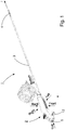
- FIG. 1 an endoscope 1 with a handle 2 according to the present invention is shown. From the handle 2 the insertion tube 3 of the endoscope extends. If not influenced by any external forces the insertion tube 3 can be considered to be an essentially straight cylindrical body, the centre axis of which defines the longitudinal direction of the endoscope 1 and the handle 2 thereof from an articulated tip part 4 at the distal end to the proximal end where the handle 3 has an inlet port 5 for a working channel.
- This definition will be assumed throughout this description. Furthermore, for the definition of directions it will be assumed that the operator is standing in an upright position holding the endoscope in front of him with the distal end, i.e.
- the articulated tip part 4 of the insertion tube pointing downward, gripping the handle with three or four fingers, so that the operating knob 14 to be operated by his thumb protrudes towards him.
- the terms to define the main outer faces will be top, bottom, front, back, left-hand and right-hand as indicated in Fig. 1 .
- the directions away from these faces will be up, down, forward, backward, left and right.
- FIG. 2 the handle of Fig. 1 is shown in greater detail.
- the view corresponds to that of Fig. 1 and accordingly only the top, back and left-hand side of the handle 2 is visible.
- the cable 6 shown in Fig. 1 for connecting the endoscope 1 to external electronics, in particular the monitor on which the images form the camera in the tip of the endoscope 1 are shown, has been omitted for illustration purposes as it is not as such of relevance to the present invention.
- the handle 2 comprises a housing which in the shown preferred embodiment comprises is made of four parts, namely a front shell part 7 a back shell part 8, a top closing part 9 and a bottom closing part 10.
- a front shell part 7 a back shell part 8
- a top closing part 9 a bottom closing part 10.
- a bottom closing part 10 a bottom closing part 10.
- it is generally the shape of the handle housing which is important, rather than the actual number of parts chosen to form the housing.
- minor defects and deviations from an ideal shape such as the groove 11 formed in the transition between the front shell part 7 and the back shell part 8 are joined, are negligible.
- the handle 2 comprises two sections which in the following, without prejudice to actual use, are referred to as gripping section 12 and operating section 13.
- the gripping section 12 is adapted to be gripped and held by three or four fingers, more specifically the third to fifth digit of the hand of the operator, i.e. the operator's middle finger, ring finger, and little finger, and optionally also the second digit, i.e. the index finger.
- Adaptation to three or four fingers should in no way be understood mutually exclusive or even separate embodiment, but should rather be understood as one embodiment allowing for either, so that the operator can chose at will.
- the operating section 13 comprises a protruding operating means such as a knob 14 adapted to be engaged by the thumb of the operator for actuation of the articulated bending section 4 of the endoscope 1 at the distal tip thereof, i.e. at the distal end of the insertion tube 3.
- the operating section 13 may optionally also comprise a push button 15 or the like for activating other functions of the endoscope 1, in particular a push button 15 for activation of suction, through a suction port 16 adapted to connect the endoscope 1 to the wall suction system normally found in hospitals and the like.
- a transition section 17 Between the gripping section 12 and the operation section 13 there is, in the preferred embodiment shown, a transition section 17.
- Fig. 3 The features of the handle 2 mentioned above in conjunction with Fig. 2 may also be seen in Fig. 3 showing the handle from a different perspective view in which the front of the gripping 12 section is better visible.
- the outer surface of the gripping section has been provided with indentations in the form of a number of grooves 18.
- These grooves 18 are approximately 1 ⁇ 2-1 mm wide and about the same in depth.
- the grooves 18 are preferably arranged side by side of each from the right-hand side to the left-hand side of the front shell part 7 (or vice versa), with a spacing from one groove 18 to the next of approximately 2-3 mm.
- the grooves 18 all preferably run transversely to the longitudinal direction of the handle 2, i.e. in the circumferential direction, but other directions are not excluded.
- the grooves 18 could run along the handle in the longitudinal direction, or across in an oblique angle, or combinations thereof. In the latter case forming a pattern of intersecting grooves 18. Grooves 18 running transversely as illustrated is however currently preferred, as they provide the most friction in the insertion direction I of the endoscope, as well as in the extraction direction. The latter is however of lesser importance, as in that case the gripping hand of the operator will normally abut the transition section 17 and thereby be prevented from slipping. This does however not exclude that the transition section may, at least in the abutment area, also be provided with grooves 18.
- the groves 18 are provided in an area with a length corresponding largely to the total width of second to fifth finger of a hand, i.e.
- grooves 18 are preferred over other indentations, e.g. dimples or the like, because the grooves 18 will serve to drain gel or the like between the operator's gloved hand and the gripping section 12 thereby reducing any lubricating effect of the gel or like, that could promote slipping.
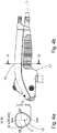
- FIGs. 4b , 5b , 6b identical side views from the left-hand side of the handle 2 for the endoscope 1 are shown.
- the side views differ only in the indication of where the respective cross-sections shown in Figs. 4a , 5a , 6a are taken, i.e. along the lines IV-IV, V-V, VI-VI respectively.
- a cross-section IV-IV through the outer gripping section surface 19 provided by the housing 2 at a location adjacent or close to the transition section 17, is shown.
- the outer gripping section surface 19 surrounds a longitudinal axis L of the handle 2.
- the cross-section IV-IV shown is thus perpendicular to the longitudinal axis L.
- the cross-section IV-IV of the gripping section surface 19 defines a periphery of a generally oval shape, in particular an egg oval shape with a pointed end and a more rounded end, not unlike the shape known from many bird's eggs.
- the periphery thus has a curvature with a varying radius r of curvature.
- the oval shape of the periphery is generally mirror symmetrical about the axis MA, in the following referred to as the major axis of the oval.
- the minimum radius r of curvature coincides with the major axis at the bottom of Fig. 4a , i.e. the front of handle 2. This minimum radius in Fig. 4a could be in the range 9 - 11 mm, preferably 10 mm or approximately 10 mm.
- this mirror symmetry extends along the gripping section 13, so as to define a plane in which both the longitudinal axis L and the major axis MA lie. That is to say a longitudinal symmetry plane intersecting the cross-section IV-IV and coincident with the longitudinal axis L.
- the symmetry allows the operator to use or grip the handle 2 of the endoscope 1 with either the left hand or the right hand as the operator pleases, when using it.
- the length I T of the major axis MA at IV-IV is preferably in the interval between 35 mm and 39 mm preferably approximately 37 mm.
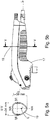
- Fig. 6a shows a cross-section VI-VI through the outer gripping section surface 19 provided by the housing 2 at a location adjacent distal end of the handle 2. Accordingly, also here the outer gripping section surface 19 surrounds the longitudinal axis L of the handle 2 and the cross-section VI-VI shown is perpendicular to the longitudinal axis L.
- the cross-section IV-IV of the gripping section surface 19 defines a periphery of a generally oval shape, in particular an egg oval shape with a pointed end and a more rounded end, although the rounded end is more rounded and the pointed end is less pointed than at the cross-section IV-IV, but still with the minimum radius r of curvature coinciding with the major axis at the front of handle 2.
- This minimum radius in Fig. 6a could be in the range 11 - 13 mm, preferably 12 mm or approximately 12 mm.
- the periphery has a curvature with a varying radius r of curvature, which varies in a manner different from that of the cross-section IV-IV.
- this oval shape of the periphery is generally mirror symmetrical about the major axis MA, i.e. the longitudinal symmetry plane intersecting the cross-sections IV-IV and VI-VI and coincident with the longitudinal axis L.
- the length l D of the major axis MA at VI-VI is preferably 35 mm or less, preferably approximately 33 mm.
- Fig. 5a shows a cross-section V-V through the outer gripping section surface 19 provided by the housing 2 at a location intermediate the transition section 17 and the distal end of the handle 2. Also here, the outer gripping section surface 19 surrounds the longitudinal axis L of the handle 2 and the cross-section V-V shown is perpendicular to the longitudinal axis L.
- the cross-section V-V of the gripping section surface 19 defines a periphery of a generally oval shape, in particular an egg oval shape with a pointed end and a more rounded end, although the rounded end is less rounded and the pointed end is more pointed than at the cross-sections IV-IV and VI-VI, but still with the minimum radius r of curvature coinciding with the major axis at the front of handle 2.
- the periphery has a curvature with a varying radius r of curvature, which varies in a manner different from those of the cross-sections IV-IV and VI-VI, but still the oval shape of the periphery is generally mirror symmetrical about the major axis MA, i.e.
- the length l I of the major axis MA has its maximum value among all cross-sections perpendicular to the longitudinal axis L between the cross-section IV-IV at the transition section 17 and the cross-section VI-VI at the distal end. This provides the gripping surface 19 with the profile readily visibly in any of the figures 4b , 5b or 6b , where a hump or hogback is formed between the distal end and the transition section 17.
- the length I T of the major axis MA at IV-IV is preferably in the interval between 35 mm and 39 mm preferably approximately 37 mm.
- the minimum radius r of curvature at the cross-section V-V is also preferably the minimum value of all radii r of curvature of all cross-sections perpendicular to the axis L between the cross-section VI-VI at the distal end to the cross-section IV-IV at the transition section 17, making the hogback more pronounced and improving the sense of direction to the operator gripping the handle 2 at the gripping section 12 as well as the rotary slippage prevention.
- This minimum value of the radius r is preferably less than 10 mm, more preferred less than 9 mm.
- the minimum radius r of curvature at the cross-section VI-VI is larger than the minimum radius r of curvature at the cross-section IV-IV (see Fig. 4b ).
- the maximum width of the handle 2 varies along the length thereof. Unlike the front-to-back dimensions along the major axes MA, the width varies continuously, increasing constantly from the distal end of endoscope 1 to the transition section 17.
- the location of the maximum width is referred to as the minor axis MI extending orthogonally to the major axis MA, as can be seen in any of Figs. 4a , 5a or 6a .
- the intersections of the major axes MA with the minor axes MI need in no way coincide with the longitudinal axis L.
- the width w T i.e. the length of the minor axis MI is more or less the same as the length of the major axis MA, but as can be seen the cross-section IV-IV is far from circular.
- the length w T of the minor axis MI is between 34 mm and 38 mm, more specifically approximately 36 mm.
- the length of the minor axis w I is preferably between 32 mm and 36 mm, more specifically approximately 34 mm, the egg oval shape thus being more oblong as compared with the one at cross-section IV-IV.
- the width is even smaller.
- the width w D is preferably between 28 mm and 32 mm more specifically approximately 30 mm.
- the width of the handle 2 continues to increase through and past the transitions section 17 into the operating section 13 before it narrows down again towards the proximal end of the endoscope 1 at the top closing part 9. This provides good space for the parts accommodated within the operating section.
- the operator should be able to reach and push the push-button 15 with sufficient force with his index finger the maximum possible width of the operating section is limited.
- the maximum width of the operating section 13 is between 36 mm and 40 mm, more specifically approximately 38 mm.
Claims (12)
- Poignée (2) destinée à un endoscope, la poignée (2) ayant une extrémité proximale, une extrémité distale, un avant et un arrière, et la poignée (2) comprenant une section de préhension (12), une section d'actionnement (13), et une section de transition (17), la section de préhension étant séparée de la section d'actionnement par la section de transition, la section d'actionnement comprenant au moins un élément d'actionnement en saillie (14) adapté pour être actionné par le pouce d'une main d'un opérateur, la section de préhension étant adaptée pour être saisie par trois ou quatre doigts de la main de l'opérateur, la section de préhension (12) ayant une surface de section de préhension externe (19) entourant un axe longitudinal (L) de la poignée, ladite surface de section de préhension externe (19) définissant une périphérie avec une courbure prédéterminée de formes de section de préhension transversale dans un plan perpendiculaire à l'axe longitudinal (L) à des points le long de l'axe longitudinal, lesdites formes de section de préhension transversale variant le long de l'axe longitudinal,
et chaque forme de section de préhension transversale étant généralement symétrique par rapport à un axe principal (MA) défini par l'intersection de la forme de section de préhension transversale avec un plan longitudinal coïncidant avec l'axe longitudinal, la section d'actionnement (13) ayant une surface de section d'actionnement externe entourant l'axe longitudinal de la poignée, ladite surface de section d'actionnement externe définissant une périphérie de formes de section d'actionnement transversale dans un plan perpendiculaire à l'axe longitudinal à des points le long de l'axe longitudinal, la longueur de la périphérie d'une forme de section de préhension transversale adjacente à la section de transition (17) étant inférieure à la longueur de la périphérie d'une forme de section d'actionnement transversale adjacente à la section de transition, chaque forme de section de préhension transversale étant asymétrique par rapport à un axe mineur (MI) définissant une largeur maximale de la forme de section de préhension transversale, caractérisé en ce que le rayon (r) de courbure de la périphérie de chaque forme de section de préhension transversale varie le long de sa longueur de façon à présenter une valeur minimale à un rayon coïncidant avec l'axe principal (MA) à l'avant de la poignée. - Poignée selon la revendication 1, le rayon (r) de courbure de la périphérie de chaque forme de section de préhension transversale variant le long de sa longueur de façon à présenter une valeur maximale coïncidant avec l'axe principal (MA) à l'arrière de la poignée.
- Poignée selon l'une quelconque des revendications précédentes, la longueur de l'axe principal (MA) à une section transversale intermédiaire prise entre une section transversale à l'extrémité distale de la poignée (2) et une section transversale prise de manière adjacente à la section de transition (17) étant plus grande que la longueur de l'axe principal de la section transversale prise de manière adjacente à la section de transition.
- Poignée selon l'une quelconque des revendications précédentes, la longueur de l'axe principal (MA) au niveau d'une section transversale intermédiaire prise entre une section transversale à l'extrémité distale de la poignée (2) et une section transversale prise de manière adjacente à la section de transition (17) étant plus grande que la longueur de l'axe principal de la section transversale prise à l'extrémité distale de la poignée.
- Poignée selon l'une quelconque des revendications précédentes, la valeur minimale du rayon (r) de courbure étant inférieure à 10 mm, de préférence inférieure à 9 mm.
- Poignée selon l'une quelconque des revendications 3 à 5, la longueur de l'axe principal (MA) au niveau de la section intermédiaire étant comprise entre 37 mm et 41 mm.
- Poignée selon l'une quelconque des revendications 3 à 5, la longueur de l'axe principal (MA) au niveau de la section transversale prise de manière adjacente à la section de transition étant comprise entre 35 mm et 39 mm.
- Poignée selon l'une quelconque des revendications 3 à 5, la longueur de l'axe principal (MA) au niveau de la section transversale prise au niveau de l'extrémité distale étant inférieure ou égale à 35 mm.
- Poignée selon l'une quelconque des revendications précédentes, la section de préhension (12) comprenant des indentations prévues dans la surface de section de préhension externe (19).
- Poignée selon l'une quelconque des revendications précédentes, les indentations comprenant un certain nombre de rainures (18).
- Poignée selon la revendication 10, lesdites rainures s'étendant dans la direction circonférentielle de la surface de section de préhension externe (19).
- Endoscope (1) avec une poignée (2) selon l'une quelconque des revendications précédentes.
Priority Applications (1)
| Application Number | Priority Date | Filing Date | Title |
|---|---|---|---|
| EP21178014.3A EP3906837B1 (fr) | 2017-03-08 | 2018-03-07 | Poignée pour endoscope |
Applications Claiming Priority (4)
| Application Number | Priority Date | Filing Date | Title |
|---|---|---|---|
| DKPA201770168 | 2017-03-08 | ||
| DKPA201770167 | 2017-03-08 | ||
| DKPA201770198 | 2017-03-21 | ||
| PCT/EP2018/055611 WO2018162561A1 (fr) | 2017-03-08 | 2018-03-07 | Poignée pour endoscope |
Related Child Applications (1)
| Application Number | Title | Priority Date | Filing Date |
|---|---|---|---|
| EP21178014.3A Division EP3906837B1 (fr) | 2017-03-08 | 2018-03-07 | Poignée pour endoscope |
Publications (2)
| Publication Number | Publication Date |
|---|---|
| EP3592199A1 EP3592199A1 (fr) | 2020-01-15 |
| EP3592199B1 true EP3592199B1 (fr) | 2021-06-09 |
Family
ID=61911519
Family Applications (2)
| Application Number | Title | Priority Date | Filing Date |
|---|---|---|---|
| EP18716112.0A Active EP3592199B1 (fr) | 2017-03-08 | 2018-03-07 | Poignée pour endoscope |
| EP21178014.3A Active EP3906837B1 (fr) | 2017-03-08 | 2018-03-07 | Poignée pour endoscope |
Family Applications After (1)
| Application Number | Title | Priority Date | Filing Date |
|---|---|---|---|
| EP21178014.3A Active EP3906837B1 (fr) | 2017-03-08 | 2018-03-07 | Poignée pour endoscope |
Country Status (4)
| Country | Link |
|---|---|
| US (2) | US11202554B2 (fr) |
| EP (2) | EP3592199B1 (fr) |
| CN (1) | CN110381799B (fr) |
| WO (1) | WO2018162561A1 (fr) |
Families Citing this family (10)
| Publication number | Priority date | Publication date | Assignee | Title |
|---|---|---|---|---|
| CN110381799B (zh) * | 2017-03-08 | 2021-12-10 | 安布股份有限公司 | 用于内窥镜的手柄 |
| JP1612252S (fr) * | 2017-09-08 | 2018-08-27 | ||
| JP1612251S (fr) * | 2017-09-08 | 2018-08-27 | ||
| USD936221S1 (en) | 2018-10-02 | 2021-11-16 | Ambu A/S | Endoscope handle |
| USD945612S1 (en) | 2018-10-02 | 2022-03-08 | Ambu A/S | Endoscope handle |
| USD1001280S1 (en) | 2019-06-18 | 2023-10-10 | Ambu A/S | Endoscope handle |
| USD975275S1 (en) * | 2019-08-15 | 2023-01-10 | Auris Health, Inc. | Handle for a medical instrument |
| CN117320609A (zh) | 2021-05-20 | 2023-12-29 | 安布股份有限公司 | 具有人体工程学手柄的内窥镜 |
| WO2023066917A1 (fr) * | 2021-10-19 | 2023-04-27 | Ambu A/S | Poignée d'endoscope et endoscope doté d'une poignée |
| USD1015535S1 (en) * | 2021-12-03 | 2024-02-20 | Ambu A/S | Endoscope handle |
Family Cites Families (56)
| Publication number | Priority date | Publication date | Assignee | Title |
|---|---|---|---|---|
| US609570A (en) | 1898-08-23 | bowden | ||
| US3897775A (en) | 1973-09-07 | 1975-08-05 | Olympus Optical Co | Endoscope with facile bending operation |
| US4203430A (en) | 1976-12-16 | 1980-05-20 | Nagashige Takahashi | Device for controlling curvature of an end section in an endoscope |
| DE3214615C2 (de) | 1981-04-21 | 1985-04-25 | Kabushiki Kaisha Medos Kenkyusho, Tokio/Tokyo | Krümmungssteuerungsanordnung für ein Endoskop |
| JPS57183822A (en) | 1981-05-01 | 1982-11-12 | Olympus Optical Co | Endoscope |
| US5179934A (en) | 1990-02-20 | 1993-01-19 | Olympus Optical Co., Ltd. | Endoscope |
| JPH03264041A (ja) | 1990-03-14 | 1991-11-25 | Machida Endscope Co Ltd | 湾曲操作装置 |
| JPH0452614A (ja) | 1990-06-20 | 1992-02-20 | Olympus Optical Co Ltd | 内視鏡 |
| US5512035A (en) | 1994-10-27 | 1996-04-30 | Circon Corporation, A Delaware Corporation | Cable compensating mechanism for an endoscope |
| US6210337B1 (en) | 1995-06-07 | 2001-04-03 | Atl Ultrasound Inc. | Ultrasonic endoscopic probe |
| DE19650721C2 (de) | 1996-12-06 | 1999-08-12 | Wolf Gmbh Richard | Steuervorrichtung zum Lenken des distalen Endes eines Endoskops |
| US5976075A (en) * | 1997-12-15 | 1999-11-02 | University Of Massachusetts | Endoscope deployment apparatus |
| JP3729322B2 (ja) * | 2000-02-03 | 2005-12-21 | フジノン株式会社 | 内視鏡の手元操作部 |
| JP3765218B2 (ja) | 2000-02-03 | 2006-04-12 | フジノン株式会社 | 内視鏡の操作ワイヤガイド装置 |
| JP4047563B2 (ja) | 2001-09-05 | 2008-02-13 | オリンパス株式会社 | 内視鏡 |
| US6830545B2 (en) | 2002-05-13 | 2004-12-14 | Everest Vit | Tube gripper integral with controller for endoscope of borescope |
| US7591783B2 (en) | 2003-04-01 | 2009-09-22 | Boston Scientific Scimed, Inc. | Articulation joint for video endoscope |
| US20050192592A1 (en) * | 2004-02-27 | 2005-09-01 | Cook Urological Incorporated | Self-tensioning handle for endoscopic device |
| US7428444B2 (en) | 2006-03-30 | 2008-09-23 | Siemens Product Lifecycle Management Software Inc. | Method for under-sizing electrodes for polygonal orbit electric discharge machining |
| US20070232858A1 (en) | 2006-03-31 | 2007-10-04 | Boston Scientific Scimed, Inc. | Steering system tension control devices |
| WO2007136894A2 (fr) * | 2006-05-19 | 2007-11-29 | Ams Research Corporation | Poignée destinée à un endoscope multifonction |
| EP2604309A1 (fr) | 2006-05-19 | 2013-06-19 | Boston Scientific Limited | Méchanism de commande pour dispositif médical orientable |
| JP4970870B2 (ja) * | 2006-08-10 | 2012-07-11 | オリンパスメディカルシステムズ株式会社 | 内視鏡の操作装置 |
| JP4497379B2 (ja) | 2006-08-23 | 2010-07-07 | 朝日インテック株式会社 | 医療用処置具 |
| JP5139742B2 (ja) * | 2007-08-03 | 2013-02-06 | オリンパスメディカルシステムズ株式会社 | 内視鏡 |
| EP2039931B1 (fr) | 2007-09-18 | 2012-06-06 | Olympus Medical Systems Corp. | Actionneur et dispositif de capture d'image |
| US7922063B2 (en) * | 2007-10-31 | 2011-04-12 | Tyco Healthcare Group, Lp | Powered surgical instrument |
| US20110009694A1 (en) * | 2009-07-10 | 2011-01-13 | Schultz Eric E | Hand-held minimally dimensioned diagnostic device having integrated distal end visualization |
| US8834357B2 (en) | 2008-11-12 | 2014-09-16 | Boston Scientific Scimed, Inc. | Steering mechanism |
| WO2010066787A1 (fr) | 2008-12-10 | 2010-06-17 | Ambu A/S | Système d'imagerie avec partie jetable |
| WO2010066789A1 (fr) * | 2008-12-10 | 2010-06-17 | Ambu A/S | Mécanisme de commande de section de courbure d'endoscope |
| US9986902B2 (en) * | 2009-03-31 | 2018-06-05 | Dilon Technologies, Inc. | Laryngoscope, laryngoscope arm and laryngoscope system |
| JP4709952B2 (ja) * | 2009-07-29 | 2011-06-29 | オリンパスメディカルシステムズ株式会社 | 内視鏡装置 |
| US20110257477A1 (en) | 2010-04-19 | 2011-10-20 | Beacon Endoscopic Corporation | Endoscopic Mucosal Resection (EMR) Over-Sheath and Methods |
| US9636092B2 (en) * | 2010-07-17 | 2017-05-02 | Debra A. KING | Methods and systems for minimally invasive endoscopic surgeries |
| JP5155494B2 (ja) | 2010-11-09 | 2013-03-06 | オリンパスメディカルシステムズ株式会社 | 内視鏡用撮像装置 |
| US8771173B2 (en) * | 2010-12-14 | 2014-07-08 | Saint Joseph's Translational Research Institute, Inc. | Access device for surgery |
| EP2779885B1 (fr) * | 2011-11-16 | 2017-04-19 | Coloplast A/S | Dispositif d'actionnement spécialement conçu pour réaliser une opération à l'intérieur du corps d'un être vivant |
| WO2013099390A1 (fr) | 2011-12-28 | 2013-07-04 | オリンパスメディカルシステムズ株式会社 | Endoscope |
| US20140012075A1 (en) * | 2012-07-09 | 2014-01-09 | Gyrus Acmi, Inc., D.B.A. Olympus Surgical Technologies America | Sinus endoscope |
| USD719651S1 (en) | 2013-01-04 | 2014-12-16 | Ambu A/S | Handle for a medical device |
| EP2958480A1 (fr) | 2013-02-22 | 2015-12-30 | Ambu A/S | Moyen pour maintenir un fil de traction tendu dans un endoscope |
| US9370295B2 (en) | 2014-01-13 | 2016-06-21 | Trice Medical, Inc. | Fully integrated, disposable tissue visualization device |
| US9937323B2 (en) * | 2014-02-28 | 2018-04-10 | Cook Medical Technologies Llc | Deflectable catheters, systems, and methods for the visualization and treatment of bodily passages |
| CN105873494B (zh) * | 2014-05-16 | 2018-04-27 | 奥林巴斯株式会社 | 内窥镜 |
| CN104382551B (zh) * | 2014-11-20 | 2017-01-18 | 江门大诚医疗器械有限公司 | 带图像收集功能的扩阴器及基于该扩阴器的图像收集系统 |
| FR3030023B1 (fr) | 2014-12-15 | 2019-10-25 | Commissariat A L'energie Atomique Et Aux Energies Alternatives | Systeme de mise en mouvement de rotation d'un ensemble de reflecteurs d'une centrale solaire a concentration et centrale solaire a concentration comprenant un tel systeme |
| WO2016188538A1 (fr) | 2015-05-27 | 2016-12-01 | Ambu A/S | Endoscope comprenant un châssis à structure de coque |
| CN107735010B (zh) | 2015-05-27 | 2020-02-18 | 安布股份有限公司 | 内窥镜 |
| JP2017006217A (ja) * | 2015-06-17 | 2017-01-12 | 富士フイルム株式会社 | コネクタ |
| EP3207854A4 (fr) | 2015-06-29 | 2018-08-08 | Olympus Corporation | Endoscope |
| WO2017030036A1 (fr) * | 2015-08-18 | 2017-02-23 | オリンパス株式会社 | Endoscope |
| CN105327443B (zh) * | 2015-11-20 | 2018-06-19 | 宋明全 | 一种消化内科用胃镜上药器 |
| CN205758497U (zh) * | 2016-05-31 | 2016-12-07 | 北京合峰联康投资管理有限公司 | 一种超细内窥镜 |
| US9737203B1 (en) * | 2017-02-22 | 2017-08-22 | Sulang Rosado | Anti-slip speculum grip and methods of using same |
| CN110381799B (zh) * | 2017-03-08 | 2021-12-10 | 安布股份有限公司 | 用于内窥镜的手柄 |
-
2018
- 2018-03-07 CN CN201880014861.1A patent/CN110381799B/zh active Active
- 2018-03-07 EP EP18716112.0A patent/EP3592199B1/fr active Active
- 2018-03-07 US US16/492,064 patent/US11202554B2/en active Active
- 2018-03-07 EP EP21178014.3A patent/EP3906837B1/fr active Active
- 2018-03-07 WO PCT/EP2018/055611 patent/WO2018162561A1/fr unknown
-
2021
- 2021-12-02 US US17/540,647 patent/US20220087506A1/en active Pending
Also Published As
| Publication number | Publication date |
|---|---|
| EP3906837A1 (fr) | 2021-11-10 |
| EP3592199A1 (fr) | 2020-01-15 |
| EP3906837B1 (fr) | 2023-08-09 |
| US20220087506A1 (en) | 2022-03-24 |
| EP3906837C0 (fr) | 2023-08-09 |
| WO2018162561A1 (fr) | 2018-09-13 |
| CN110381799A (zh) | 2019-10-25 |
| US20210275001A1 (en) | 2021-09-09 |
| CN110381799B (zh) | 2021-12-10 |
| US11202554B2 (en) | 2021-12-21 |
Similar Documents
| Publication | Publication Date | Title |
|---|---|---|
| EP3592199B1 (fr) | Poignée pour endoscope | |
| JP6887997B2 (ja) | 無制限ロールを付与するハンドル機構 | |
| EP3310290B1 (fr) | Appareil de préhension manuelle pour recevoir une entrée opérateur dans un système de chirurgie robotique | |
| EP3050488A1 (fr) | Endoscope | |
| EP3078318B1 (fr) | Endoscope | |
| US20190053690A1 (en) | Endoscope | |
| EP3158910A1 (fr) | Dispositif formant endoscope | |
| US10709314B2 (en) | Endoscope tool position holder | |
| US10201362B2 (en) | Contoured surgical forceps | |
| EP3207854A1 (fr) | Endoscope | |
| US20100324577A1 (en) | Scalpel handle | |
| US20170354401A1 (en) | Ergonomic multi-functional handle for use with a medical instrument | |
| US10058311B1 (en) | Ergonomic multi-functional handle for use with a medical instrument | |
| JP6124819B2 (ja) | 内視鏡用操作部及び内視鏡 | |
| CN109715032B (zh) | 插入器械 | |
| EP3199088A1 (fr) | Endoscope | |
| JP6943550B2 (ja) | マウス | |
| JP6219008B1 (ja) | 内視鏡 | |
| WO2011131972A1 (fr) | Poignée et instrument chirurgical | |
| EP3081141A1 (fr) | Section d'actionnement pour un dispositif d'introduction dans une ouverture, et dispositif d'introduction dans une ouverture | |
| JP2000126194A (ja) | 内視鏡用処置具の操作部 | |
| JP6042797B2 (ja) | 孔内導入装置用操作部及び孔内導入装置 | |
| WO2023066917A1 (fr) | Poignée d'endoscope et endoscope doté d'une poignée |
Legal Events
| Date | Code | Title | Description |
|---|---|---|---|
| STAA | Information on the status of an ep patent application or granted ep patent |
Free format text: STATUS: UNKNOWN |
|
| STAA | Information on the status of an ep patent application or granted ep patent |
Free format text: STATUS: THE INTERNATIONAL PUBLICATION HAS BEEN MADE |
|
| PUAI | Public reference made under article 153(3) epc to a published international application that has entered the european phase |
Free format text: ORIGINAL CODE: 0009012 |
|
| STAA | Information on the status of an ep patent application or granted ep patent |
Free format text: STATUS: REQUEST FOR EXAMINATION WAS MADE |
|
| 17P | Request for examination filed |
Effective date: 20190807 |
|
| AK | Designated contracting states |
Kind code of ref document: A1 Designated state(s): AL AT BE BG CH CY CZ DE DK EE ES FI FR GB GR HR HU IE IS IT LI LT LU LV MC MK MT NL NO PL PT RO RS SE SI SK SM TR |
|
| AX | Request for extension of the european patent |
Extension state: BA ME |
|
| RIN1 | Information on inventor provided before grant (corrected) |
Inventor name: HANSEN, MICHAEL KAPPLER Inventor name: LUND, JESPER GROENDAHL |
|
| DAV | Request for validation of the european patent (deleted) | ||
| DAX | Request for extension of the european patent (deleted) | ||
| GRAP | Despatch of communication of intention to grant a patent |
Free format text: ORIGINAL CODE: EPIDOSNIGR1 |
|
| STAA | Information on the status of an ep patent application or granted ep patent |
Free format text: STATUS: GRANT OF PATENT IS INTENDED |
|
| INTG | Intention to grant announced |
Effective date: 20210113 |
|
| GRAS | Grant fee paid |
Free format text: ORIGINAL CODE: EPIDOSNIGR3 |
|
| GRAA | (expected) grant |
Free format text: ORIGINAL CODE: 0009210 |
|
| STAA | Information on the status of an ep patent application or granted ep patent |
Free format text: STATUS: THE PATENT HAS BEEN GRANTED |
|
| AK | Designated contracting states |
Kind code of ref document: B1 Designated state(s): AL AT BE BG CH CY CZ DE DK EE ES FI FR GB GR HR HU IE IS IT LI LT LU LV MC MK MT NL NO PL PT RO RS SE SI SK SM TR |
|
| REG | Reference to a national code |
Ref country code: GB Ref legal event code: FG4D |
|
| REG | Reference to a national code |
Ref country code: CH Ref legal event code: EP Ref country code: AT Ref legal event code: REF Ref document number: 1399799 Country of ref document: AT Kind code of ref document: T Effective date: 20210615 |
|
| REG | Reference to a national code |
Ref country code: DE Ref legal event code: R096 Ref document number: 602018018363 Country of ref document: DE |
|
| REG | Reference to a national code |
Ref country code: IE Ref legal event code: FG4D |
|
| REG | Reference to a national code |
Ref country code: LT Ref legal event code: MG9D |
|
| PG25 | Lapsed in a contracting state [announced via postgrant information from national office to epo] |
Ref country code: HR Free format text: LAPSE BECAUSE OF FAILURE TO SUBMIT A TRANSLATION OF THE DESCRIPTION OR TO PAY THE FEE WITHIN THE PRESCRIBED TIME-LIMIT Effective date: 20210609 Ref country code: LT Free format text: LAPSE BECAUSE OF FAILURE TO SUBMIT A TRANSLATION OF THE DESCRIPTION OR TO PAY THE FEE WITHIN THE PRESCRIBED TIME-LIMIT Effective date: 20210609 Ref country code: FI Free format text: LAPSE BECAUSE OF FAILURE TO SUBMIT A TRANSLATION OF THE DESCRIPTION OR TO PAY THE FEE WITHIN THE PRESCRIBED TIME-LIMIT Effective date: 20210609 Ref country code: BG Free format text: LAPSE BECAUSE OF FAILURE TO SUBMIT A TRANSLATION OF THE DESCRIPTION OR TO PAY THE FEE WITHIN THE PRESCRIBED TIME-LIMIT Effective date: 20210909 |
|
| REG | Reference to a national code |
Ref country code: AT Ref legal event code: MK05 Ref document number: 1399799 Country of ref document: AT Kind code of ref document: T Effective date: 20210609 |
|
| REG | Reference to a national code |
Ref country code: NL Ref legal event code: MP Effective date: 20210609 |
|
| PG25 | Lapsed in a contracting state [announced via postgrant information from national office to epo] |
Ref country code: SE Free format text: LAPSE BECAUSE OF FAILURE TO SUBMIT A TRANSLATION OF THE DESCRIPTION OR TO PAY THE FEE WITHIN THE PRESCRIBED TIME-LIMIT Effective date: 20210609 Ref country code: RS Free format text: LAPSE BECAUSE OF FAILURE TO SUBMIT A TRANSLATION OF THE DESCRIPTION OR TO PAY THE FEE WITHIN THE PRESCRIBED TIME-LIMIT Effective date: 20210609 Ref country code: NO Free format text: LAPSE BECAUSE OF FAILURE TO SUBMIT A TRANSLATION OF THE DESCRIPTION OR TO PAY THE FEE WITHIN THE PRESCRIBED TIME-LIMIT Effective date: 20210909 Ref country code: LV Free format text: LAPSE BECAUSE OF FAILURE TO SUBMIT A TRANSLATION OF THE DESCRIPTION OR TO PAY THE FEE WITHIN THE PRESCRIBED TIME-LIMIT Effective date: 20210609 Ref country code: GR Free format text: LAPSE BECAUSE OF FAILURE TO SUBMIT A TRANSLATION OF THE DESCRIPTION OR TO PAY THE FEE WITHIN THE PRESCRIBED TIME-LIMIT Effective date: 20210910 |
|
| PG25 | Lapsed in a contracting state [announced via postgrant information from national office to epo] |
Ref country code: SK Free format text: LAPSE BECAUSE OF FAILURE TO SUBMIT A TRANSLATION OF THE DESCRIPTION OR TO PAY THE FEE WITHIN THE PRESCRIBED TIME-LIMIT Effective date: 20210609 Ref country code: SM Free format text: LAPSE BECAUSE OF FAILURE TO SUBMIT A TRANSLATION OF THE DESCRIPTION OR TO PAY THE FEE WITHIN THE PRESCRIBED TIME-LIMIT Effective date: 20210609 Ref country code: EE Free format text: LAPSE BECAUSE OF FAILURE TO SUBMIT A TRANSLATION OF THE DESCRIPTION OR TO PAY THE FEE WITHIN THE PRESCRIBED TIME-LIMIT Effective date: 20210609 Ref country code: ES Free format text: LAPSE BECAUSE OF FAILURE TO SUBMIT A TRANSLATION OF THE DESCRIPTION OR TO PAY THE FEE WITHIN THE PRESCRIBED TIME-LIMIT Effective date: 20210609 Ref country code: RO Free format text: LAPSE BECAUSE OF FAILURE TO SUBMIT A TRANSLATION OF THE DESCRIPTION OR TO PAY THE FEE WITHIN THE PRESCRIBED TIME-LIMIT Effective date: 20210609 Ref country code: PT Free format text: LAPSE BECAUSE OF FAILURE TO SUBMIT A TRANSLATION OF THE DESCRIPTION OR TO PAY THE FEE WITHIN THE PRESCRIBED TIME-LIMIT Effective date: 20211011 Ref country code: NL Free format text: LAPSE BECAUSE OF FAILURE TO SUBMIT A TRANSLATION OF THE DESCRIPTION OR TO PAY THE FEE WITHIN THE PRESCRIBED TIME-LIMIT Effective date: 20210609 Ref country code: AT Free format text: LAPSE BECAUSE OF FAILURE TO SUBMIT A TRANSLATION OF THE DESCRIPTION OR TO PAY THE FEE WITHIN THE PRESCRIBED TIME-LIMIT Effective date: 20210609 Ref country code: CZ Free format text: LAPSE BECAUSE OF FAILURE TO SUBMIT A TRANSLATION OF THE DESCRIPTION OR TO PAY THE FEE WITHIN THE PRESCRIBED TIME-LIMIT Effective date: 20210609 |
|
| PG25 | Lapsed in a contracting state [announced via postgrant information from national office to epo] |
Ref country code: PL Free format text: LAPSE BECAUSE OF FAILURE TO SUBMIT A TRANSLATION OF THE DESCRIPTION OR TO PAY THE FEE WITHIN THE PRESCRIBED TIME-LIMIT Effective date: 20210609 |
|
| REG | Reference to a national code |
Ref country code: DE Ref legal event code: R097 Ref document number: 602018018363 Country of ref document: DE |
|
| PLBE | No opposition filed within time limit |
Free format text: ORIGINAL CODE: 0009261 |
|
| STAA | Information on the status of an ep patent application or granted ep patent |
Free format text: STATUS: NO OPPOSITION FILED WITHIN TIME LIMIT |
|
| PG25 | Lapsed in a contracting state [announced via postgrant information from national office to epo] |
Ref country code: DK Free format text: LAPSE BECAUSE OF FAILURE TO SUBMIT A TRANSLATION OF THE DESCRIPTION OR TO PAY THE FEE WITHIN THE PRESCRIBED TIME-LIMIT Effective date: 20210609 |
|
| 26N | No opposition filed |
Effective date: 20220310 |
|
| PG25 | Lapsed in a contracting state [announced via postgrant information from national office to epo] |
Ref country code: AL Free format text: LAPSE BECAUSE OF FAILURE TO SUBMIT A TRANSLATION OF THE DESCRIPTION OR TO PAY THE FEE WITHIN THE PRESCRIBED TIME-LIMIT Effective date: 20210609 |
|
| PG25 | Lapsed in a contracting state [announced via postgrant information from national office to epo] |
Ref country code: IT Free format text: LAPSE BECAUSE OF FAILURE TO SUBMIT A TRANSLATION OF THE DESCRIPTION OR TO PAY THE FEE WITHIN THE PRESCRIBED TIME-LIMIT Effective date: 20210609 |
|
| PG25 | Lapsed in a contracting state [announced via postgrant information from national office to epo] |
Ref country code: MC Free format text: LAPSE BECAUSE OF FAILURE TO SUBMIT A TRANSLATION OF THE DESCRIPTION OR TO PAY THE FEE WITHIN THE PRESCRIBED TIME-LIMIT Effective date: 20210609 |
|
| REG | Reference to a national code |
Ref country code: CH Ref legal event code: PL |
|
| REG | Reference to a national code |
Ref country code: BE Ref legal event code: MM Effective date: 20220331 |
|
| PG25 | Lapsed in a contracting state [announced via postgrant information from national office to epo] |
Ref country code: LU Free format text: LAPSE BECAUSE OF NON-PAYMENT OF DUE FEES Effective date: 20220307 Ref country code: LI Free format text: LAPSE BECAUSE OF NON-PAYMENT OF DUE FEES Effective date: 20220331 Ref country code: IE Free format text: LAPSE BECAUSE OF NON-PAYMENT OF DUE FEES Effective date: 20220307 Ref country code: CH Free format text: LAPSE BECAUSE OF NON-PAYMENT OF DUE FEES Effective date: 20220331 |
|
| PG25 | Lapsed in a contracting state [announced via postgrant information from national office to epo] |
Ref country code: BE Free format text: LAPSE BECAUSE OF NON-PAYMENT OF DUE FEES Effective date: 20220331 |
|
| PGFP | Annual fee paid to national office [announced via postgrant information from national office to epo] |
Ref country code: FR Payment date: 20230217 Year of fee payment: 6 |
|
| PGFP | Annual fee paid to national office [announced via postgrant information from national office to epo] |
Ref country code: GB Payment date: 20230217 Year of fee payment: 6 Ref country code: DE Payment date: 20230220 Year of fee payment: 6 |
|
| PG25 | Lapsed in a contracting state [announced via postgrant information from national office to epo] |
Ref country code: MK Free format text: LAPSE BECAUSE OF FAILURE TO SUBMIT A TRANSLATION OF THE DESCRIPTION OR TO PAY THE FEE WITHIN THE PRESCRIBED TIME-LIMIT Effective date: 20210609 Ref country code: CY Free format text: LAPSE BECAUSE OF FAILURE TO SUBMIT A TRANSLATION OF THE DESCRIPTION OR TO PAY THE FEE WITHIN THE PRESCRIBED TIME-LIMIT Effective date: 20210609 |
|
| PGFP | Annual fee paid to national office [announced via postgrant information from national office to epo] |
Ref country code: DE Payment date: 20240216 Year of fee payment: 7 Ref country code: GB Payment date: 20240215 Year of fee payment: 7 |