EP3591322B1 - Kühl- und/oder gefriergerät - Google Patents
Kühl- und/oder gefriergerät Download PDFInfo
- Publication number
- EP3591322B1 EP3591322B1 EP19183560.2A EP19183560A EP3591322B1 EP 3591322 B1 EP3591322 B1 EP 3591322B1 EP 19183560 A EP19183560 A EP 19183560A EP 3591322 B1 EP3591322 B1 EP 3591322B1
- Authority
- EP
- European Patent Office
- Prior art keywords
- cover plate
- holding part
- illumination assembly
- light
- refrigerator
- Prior art date
- Legal status (The legal status is an assumption and is not a legal conclusion. Google has not performed a legal analysis and makes no representation as to the accuracy of the status listed.)
- Active
Links
Images


Classifications
-
- F—MECHANICAL ENGINEERING; LIGHTING; HEATING; WEAPONS; BLASTING
- F25—REFRIGERATION OR COOLING; COMBINED HEATING AND REFRIGERATION SYSTEMS; HEAT PUMP SYSTEMS; MANUFACTURE OR STORAGE OF ICE; LIQUEFACTION SOLIDIFICATION OF GASES
- F25D—REFRIGERATORS; COLD ROOMS; ICE-BOXES; COOLING OR FREEZING APPARATUS NOT OTHERWISE PROVIDED FOR
- F25D27/00—Lighting arrangements
-
- F—MECHANICAL ENGINEERING; LIGHTING; HEATING; WEAPONS; BLASTING
- F25—REFRIGERATION OR COOLING; COMBINED HEATING AND REFRIGERATION SYSTEMS; HEAT PUMP SYSTEMS; MANUFACTURE OR STORAGE OF ICE; LIQUEFACTION SOLIDIFICATION OF GASES
- F25D—REFRIGERATORS; COLD ROOMS; ICE-BOXES; COOLING OR FREEZING APPARATUS NOT OTHERWISE PROVIDED FOR
- F25D23/00—General constructional features
- F25D23/06—Walls
- F25D23/065—Details
- F25D23/067—Supporting elements
Definitions
- the invention relates to a refrigerator and/or freezer with a device body and an interior space enclosed by this device body, wherein a lighting arrangement with a translucent cover plate is arranged on a vertical wall of the interior space, which has support ribs for fastening a storage element.
- Such a cooling device is, for example, from the DE 10 2012 009 456 A1
- This known solution uses a direct light system, which means that the cover plate is illuminated directly by a light source.
- these direct light systems produce a very directed light, which leads to increased shadows.
- the light sources are directly visible, which means that the user is either blinded or the light is greatly weakened by the cover plate.
- the DE 10 2012 015400 A1 , the DE 10 2010 031696 A1 , the DE 10 2017 001173 A1 , the DE 10 2014 209141 A1 and the DE 10 2013 224261 A1 also reveal refrigerators with lighting.
- the object of the invention is to provide an interior lighting for refrigerators and/or freezers, which combines a holding function for storage elements with the most efficient, uniform and glare-free illumination possible.
- the invention relates to a refrigerator and/or freezer according to claim 1 with a device body and an interior space enclosed by this device body, wherein a lighting arrangement with a translucent cover plate is arranged on a vertical wall of the interior space, which has a contour for fastening a storage element, and wherein the lighting arrangement comprises a light guide plate which is arranged under the translucent cover plate.
- the interior has a front opening which is covered by a door and preferably a swing door.
- the lighting arrangement is preferably arranged on a side wall of the interior. In principle, however, it is also conceivable to attach the lighting device to the rear wall of the interior.
- the lighting arrangement according to the invention combines analogous to that from the DE 10 2012 009 456 A1
- the known solution combines the function of accommodating storage elements with the lighting function, but the light output is more uniform. In addition, it is structurally simpler to vary the dimensions of the lighting arrangement and to install the light sources in a convenient position.
- the light guide plate can be made of plastic glass. Inclusions (e.g. particles, air) can be included to scatter the light and/or surface structures (etching, printing, eroding, molding, embossing) and/or holographic structures can be provided to couple out the light.
- Inclusions e.g. particles, air
- surface structures etching, printing, eroding, molding, embossing
- holographic structures can be provided to couple out the light.
- the lighting arrangement comprises a holding part which is attached to the device body and on which both the light guide plate and the cover plate are held. It is provided that the cover plate is latched onto the holding part, for which purpose the cover plate and the holding part have corresponding latching means.
- the light guide plate can be inserted into a gap formed between the holding part and the cover plate.
- the holding part can be made of plastic, metal or wood, for example. Suitable metals include aluminum or stainless steel. Circumferential seals can preferably be provided at the interfaces between the holding part and the device inner container and/or the cover plate in order to improve the seal against moisture.
- the front of the holding part facing the light guide plate can have a reflective surface. This can increase the efficiency of the lighting arrangement. It is conceivable to make the front mirrored using an appropriate coating.
- the device body comprises an inner container and the lighting arrangement is arranged in a precisely fitting manner in a correspondingly shaped pocket of this inner container.
- the inner container can be made from a plastic plate and the pocket can be incorporated into the inner container by deep drawing.
- the lighting arrangement is positively fixed in the pocket and is locked into the pocket.
- the holding part of the lighting arrangement is positively fixed in the pocket and is locked into the pocket, for which purpose the pocket and the holding part have corresponding locking elements.
- the connection preferably does not require any additional holding parts such as screws, clamps or the like.
- the form fit can be designed in such a way that only an axial movement of the lighting arrangement within the pocket is permitted, thereby enabling direct centering and contacting is made possible during assembly without a mounting device.
- the geometries of the pocket on the one hand and the lighting arrangement or the holding part on the other hand are coordinated in such a way that a watertight installation situation is created during assembly.
- the lighting arrangement has a rectangular shape, with the long side edge extending in the vertical direction. This applies to all elements of the lighting arrangement, in particular to the cover plate, the holding part and the light guide plate.
- the lighting arrangement can have a light source which is arranged in such a way that it introduces light into one or more side edges of the light guide plate.
- a surface coupling of the light i.e. not necessarily via one or more edges, such as the side edge(s), is also conceivable and is included in the invention.
- the light source is preferably arranged so that light is introduced into the short side edge of the preferably rectangular light guide plate. It can be provided that at least one light source is provided through which light is introduced into different and preferably opposite side edges of the light guide plate. In a standing arrangement in the device, light is thus introduced into the light guide plate from above and/or below.
- the light source can be an LED light source and/or a laser diode.
- the light can also be coupled indirectly into the light guide plate through one or more light guides.
- the lighting arrangement can extend to the upper edge of the receiving wall.
- an arch-like appearance can be achieved.
- the contour for fastening a storage element is one or more support ribs. These support ribs are used to fasten storage elements such as shelves or drawers.
- the invention further relates to a refrigerator and/or freezer according to claim 7 with a device body and an interior space enclosed by this device body, wherein a lighting arrangement with a translucent cover plate is arranged on a vertical wall of the interior space, which has a contour for fastening a storage element, and wherein the lighting arrangement comprises a flat OLED light source which is arranged behind the translucent cover plate.
- the light guide plate can therefore be replaced by an OLED light source (organic light-emitting diode), which in itself is a surface-emitting light source.
- OLED organic light-emitting diode
- the OLED can be arranged directly on the back of the cover plate or on a carrier plate.
- the plastic inner container 10 of an embodiment of a refrigerator or freezer according to the invention according to claim 1, which can be seen in the figures, comprises a deep-drawn container pocket 20 on each of its two side walls, which is set back from the wall surface of the inner container 10 and has a base and lateral boundaries.
- the pocket 20 is rectangular in plan view, with the side edge, which is several times longer, running vertically.
- a lighting arrangement 100 is inserted into the pocket 20, which completely fills the volume of the pocket 20.
- the lighting arrangement 100 comprises a holding part 110 made of plastic fastened to the inner container 10, a cover plate 120 made of a translucent plastic material mounted on this holding part 110 and a light guide plate 130 which is inserted into a gap formed between the holding part 110 and the cover plate 120.
- the holding part 110 has several corresponding pairs of corresponding holding formations 111 with locking lugs 112. If the holding formations 111 are inserted into the holding recesses 21, the holding part 110 is held in the pocket 20 in a form-fitting manner by the interaction of the locking projections 22 and the locking lugs 112.
- the shape of the rear surface of the holding part 110 corresponds to the shape of the pocket 20, so that a suitable fit is guaranteed.
- the cover plate 120 is also attached to the front side of the holding part 110 using a locking connection, whereby the cover plate 120 has locking pins 121 on its rear side and the holding part 110 has corresponding receptacles 113.
- the front side of the holding part 110 is set back from the wall surface of the inner container 10 by a distance that corresponds to the thickness of the cover plate 120, so that according to the invention the front side of the cover plate 120 lies in the plane of the wall surface and the wall surface and the cover plate 120 merge into one another.
- a number of holding ribs 122 are formed at regular intervals one below the other, which form a horizontal support surface for shelves 30 in the interior of the refrigerator and/or freezer.
- the light guide plate 130 extends over the full length of the lighting arrangement 100. It consists of a plastic glass that has inclusions for the uniform coupling out of light over the surface of the plate 120.
- the front side of the holding part 110 which in the assembled state behind the light guide plate 130, is mirrored.
- the coupling of light into the light guide plate 130 takes place on its short sides by means of LED modules 140, which are mounted on the upper and lower end faces of the lighting arrangement 100 are inserted into corresponding formations 23 on the pockets 20 by means of separate holding parts 141.
Landscapes
- Engineering & Computer Science (AREA)
- Chemical & Material Sciences (AREA)
- Combustion & Propulsion (AREA)
- Physics & Mathematics (AREA)
- Mechanical Engineering (AREA)
- Thermal Sciences (AREA)
- General Engineering & Computer Science (AREA)
- Devices That Are Associated With Refrigeration Equipment (AREA)
Description
- Die Erfindung betrifft ein Kühl- und/oder Gefriergerät mit einem Gerätekorpus und einem von diesem Gerätekorpus umschlossenen Innenraum, wobei an einer senkrechten Wand des Innenraums eine Beleuchtungsanordnung mit einer lichtdurchlässigen Deckplatte angeordnet ist, welche Auflagerippen zur Befestigung eines Ablageelements aufweist.
- Ein derartiges Kühlgerät ist beispielsweise aus der
DE 10 2012 009 456 A1 bekannt. In dieser bekannten Lösung wird ein Direktlichtsystem verwendet, was bedeutet, dass die Deckplatte direkt von einer Lichtquelle durchleuchtet wird. Diese Direktlichtsysteme erzeugen jedoch ein sehr gerichtetes Licht, was zu einer verstärkten Schattenbildung führt. Ferner sind die Lichtquellen direkt sichtbar, wodurch entweder ein Blenden des Benutzers oder eine starke Schwächung des Lichts durch die Deckplatte in Kauf genommen werden muss. - Die
DE 10 2012 015400 A1 , dieDE 10 2010 031696 A1 , dieDE 10 2017 001173 A1 , dieDE 10 2014 209141 A1 und dieDE 10 2013 224261 A1 offenbaren ebenfalls Kühlgeräte mit einer Beleuchtung. - Aufgabe der Erfindung ist es, eine Innenraumbeleuchtung für Kühl- und/oder Gefriergerät bereitzustellen, welche eine haltende Funktion für Ablageelemente mit einer möglichst effizienten, gleichmäßigen und blendfreien Ausleuchtung verbindet.
- Die vorliegende Erfindung ist in den unabhängigen Ansprüchen 1 und 7 offenbart. Weitere Ausführungsbeispiele sind in den abhängigen Ansprüchen offenbart.
- Vor diesem Hintergrund betrifft die Erfindung ein Kühl- und/oder Gefriergerät nach dem Anspruch 1 mit einem Gerätekorpus und einem von diesem Gerätekorpus umschlossenen Innenraum, wobei an einer senkrechten Wand des Innenraums eine Beleuchtungsanordnung mit einer lichtdurchlässigen Deckplatte angeordnet ist, welche eine Kontur zur Befestigung eines Ablageelements aufweist, und wobei die Beleuchtungsanordnung eine Lichtleitplatte umfasst, welche unter der lichtdurchlässigen Deckplatte angeordnet ist.
- Der Innenraum weist eine frontseitige Öffnung auf, welche von einer Türe und vorzugsweise Schwenktüre abgedeckt ist. Die Beleuchtungsanordnung ist vorzugsweise an einer Seitenwand des Innenraums angeordnet. Grundsätzlich ist es aber auch denkbar, die Beleuchtungsvorrichtung an der Rückwand des Innenraums anzubringen.
- Die erfindungsgemäße Beleuchtungsanordnung vereinigt analog der aus der
DE 10 2012 009 456 A1 bekannten Lösung die Funktion der Aufnahme von Ablageelementen mit der Beleuchtungsfunktion, allerdings ist die Lichtabgabe gleichmäßiger. Zudem ist es baulich einfacher, die Dimensionen der Beleuchtungsanordnung zu variieren und die Lichtquellen an einer günstigen Position anzubringen. - Die Lichtleiterplatte kann aus einem Kunststoffglas bestehen. Zur Auskopplung des Lichts können Einschlüsse (z.B. Partikel, Luft) zur Ausstreuung des Lichts eingeschlossen sein und/oder Oberflächenstrukturen (Ätzen, Bedrucken, Erodieren, Abformen, Prägen) und/oder holographische Strukturen vorgesehen sein.
- Die Beleuchtungsanordnung umfasst erfindungsgemäß ein Halteteil, welches am Gerätekorpus befestigt ist und an dem sowohl die Lichtleiterplatte als auch die Deckplatte gehalten sind. Es ist vorgesehen, dass die Deckplatte auf das Halteteil gerastet ist, wozu die Deckplatte und das Halteteil korrespondierende Rastmittel aufweisen. Die Lichtleiterplatte kann in einen zwischen dem Halteteil und die Deckplatte ausgebildeten Zwischenraum eingesetzt sein. Das Halteteil kann beispielsweise aus Kunststoff, Metall oder Holz gefertigt sein. Geeignete Metalle umfassen Aluminium oder Edelstahl. An den Grenzflächen zwischen dem Halteteil und dem Geräteinnenbehälter und/oder der Deckplatte können vorzugsweise umlaufende Dichtungen vorgesehen sein, um die Abdichtung gegenüber Feuchtigkeit zu verbessern.
- Die der Lichtleiterplatte zugewandte Front des Halteteils kann eine reflektierende Oberfläche aufweisen. Dadurch kann die Effizienz der Beleuchtungsanordnung gesteigert werden. Denkbar ist eine Verspiegelung der Front durch entsprechende Beschichtung.
- Der Gerätekorpus umfasst erfindungsgemäß einen Innenbehälter und die Beleuchtungsanordnung ist passgenau in einer korrespondierend geformten Tasche dieses Innenbehälters angeordnet. Der Innenbehälter kann aus eine Kunststoffplatine gefertigt und die Tasche durch Tiefziehen in den Innenbehälter eingearbeitet sein.
- Die Beleuchtungsanordnung ist formschlüssig in der Tasche fixiert und ist in die Tasche gerastet. Dabei ist das Halteteil der Beleuchtungsanordnung formschlüssig in der Tasche fixiert und in die Tasche gerastet, wozu die Tasche und das Halteteil korrespondierende Rastelemente aufweisen. Vorzugsweise kommt die Verbindung ohne zusätzliche Halteteile wie etwa Schrauben, Klammern, oder dergleichen aus.
- Der Formschluss kann so ausgebildet sein, dass nur eine axiale Bewegung der Beleuchtungsanordnung innerhalb der Tasche erlaubt ist, wodurch eine direkte Zentrierung und Kontaktierung bei der Montage ohne Montagevorrichtung ermöglicht wird. Vorzugsweise sind die Geometrien der Tasche einerseits und der Beleuchtungsanordnung bzw. der Halteteils andererseits so aufeinander abgestimmt, dass bei der Montage eine wasserdichte Einbausituation entsteht.
- In einer Ausführungsform ist vorgesehen, dass die Beleuchtungsanordnung eine rechteckige Gestalt hat, wobei sich die lange Seitenkante in vertikaler Richtung erstreckt. Dies gilt für alle Elemente der Beleuchtungsanordnung, insbesondere für die Deckplatte, das Halteteil und die Lichtleitplatte.
- Die Beleuchtungsanordnung kann eine Lichtquelle aufweisen, welche so angeordnet ist, dass sie Licht in eine oder mehrere Seitenkanten der Lichtleitplatte einleitet. Auch eine flächige Einkopplung des Lichtes, also nicht zwingend über eine oder mehrere Kanten, wie z.B. die Seitenkante(n) ist denkbar und von der Erfindung mit umfasst.
- Vorzugsweise ist die Lichtquelle so angeordnet, dass Licht in die kurze Seitenkante der vorzugsweise rechteckigen Lichtleitplatte eingeleitet wird. Es kann vorgesehen sein, dass wenigstens eine Lichtquelle vorgesehen ist, durch welche Licht in unterschiedliche und vorzugsweise gegenüberliegende Seitenkanten der Lichtleitplatte eingeleitet wird. Bei einer stehenden Anordnung im Gerät wird Licht also von oben und/oder unten in die Lichtleitplatte eingeleitet.
- Bei der Lichtquelle kann es sich um eine LED-Lichtquelle und/oder um eine Laserdiode handeln. Alternativ kann das Licht auch indirekt durch einen oder mehrere Lichtleiter in die Lichtleitplatte eingekoppelt werden.
- Die Beleuchtungsanordnung kann in einer Ausführungsform bis an die Oberkante der aufnehmenden Wand reichen. So kann beispielsweise in Verbindung mit einer an der Decke des Innenbehälters angeordneten Lichtquelle ein Bogenartiges Erscheinungsbild erreicht werden.
- Erfindungsgemäß ist vorgesehen, dass es sich bei der Kontur zur Befestigung eines Ablageelements um eine oder mehrere Auflagerippen handelt. Diese Auflagerippen dienen zu Befestigung von Ablageelementen wie beispielsweise Ablageböden oder Schubladen.
- Vor dem eingangs genannten Hintergrund betrifft die Erfindung ferner ein Kühl- und/oder Gefriergerät nach Anspruch 7 mit einem Gerätekorpus und einem von diesem Gerätekorpus umschlossenen Innenraum, wobei an einer senkrechten Wand des Innenraums eine Beleuchtungsanordnung mit einer lichtdurchlässigen Deckplatte angeordnet ist, welche eine Kontur zur Befestigung eines Ablageelements aufweist, und wobei die Beleuchtungsanordnung eine flächige OLED-Lichtquelle umfasst, welche hinter der lichtdurchlässigen Deckplatte angeordnet ist.
- Die Lichtleitplatte kann also durch eine OLED-Lichtquelle (organische lichtemittierende Dioden) ersetzt werden, welche an sich schon eine flächenemittierende Lichtquelle darstellt. Die OLED kann direkt an der Rückseite der Deckplatte oder an einer Trägerplatte angeordnet werden. Die obenstehende Diskussion bevorzugter Ausgestaltungen der Beleuchtungsanordnung mit Lichtleitplatte gilt für die Beleuchtungsanordnung mit einer OLED-Lichtquelle entsprechend.
- An dieser Stelle wird darauf hingewiesen, dass die Begriffe "ein" und "eine" nicht zwingend auf genau eines der Elemente verweisen, wenngleich dies eine mögliche Ausführung darstellt, sondern auch eine Mehrzahl der Elemente bezeichnen können. Ebenso schließt die Verwendung des Plurals auch das Vorhandensein des fraglichen Elementes in der Einzahl ein und umgekehrt umfasst der Singular auch mehrere der fraglichen Elemente.
- Weitere Einzelheiten und Vorteile der Erfindung ergeben sich aus den nachfolgend anhand der Figuren beschriebenen Ausführungsbeispielen. In den Figuren zeigen:
- Figur 1:
- drei perspektivische Ansichten eines Innenbehälters eines mit einer erfindungsgemäß ausgestalteten Beleuchtungsanordnung ausgestatteten Kühl- oder Gefriergerätes;
- Figur 2:
- eine Ansicht von vorne auf den Innenbehälter;
- Figur 3:
- eine Explosionsdarstellung der Beleuchtungsanordnung; und
- Figur 4:
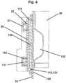
- eine horizontale Schnittansicht entlang der Ebene A-A durch Behälterwand und Beleuchtungsanordnung.
- Der in den Figuren ersichtliche Kunststoff-Innenbehälter 10 einer Ausführungsform eines erfindungsgemäßen Kühl- oder Gefriergerätes nach Anspruch 1 umfasst an seinen beiden Seitenwänden jeweils eine tiefgezogene Behältertasche 20, die gegenüber der Wandfläche des Innenbehälters 10 zurückversetzt ist und einen Boden sowie seitliche Begrenzungen aufweist. Die Tasche 20 ist in der Draufsicht rechteckig, wobei die um ein Mehrfaches längere Seitenkante senkrecht verläuft. In die Tasche 20 ist eine Beleuchtungsanordnung 100 eingesetzt, welche das Volumen der Tasche 20 vollständig ausfüllt.
- Die Beleuchtungsanordnung 100 umfasst ein am Innenbehälter 10 befestigtes Halteteil 110 aus Kunststoff, eine an diesem Halteteil 110 montierte Deckplatte 120 aus einem lichtdurchlässigen Kunststoff-Material sowie eine Lichtleiterplatte 130, die in einen zwischen dem Halteteil 110 und der Deckplatte 120 ausgebildeten Zwischenraum eingesetzt ist.
- Zur Fixierung des Halteteils 110 sind erfindungsgemäß innerhalb der Tasche 20 mehrere Paare an vertikal verlaufenden Haltevertiefungen 21 mit Rastvorsprüngen 22 vorgesehen. Das Halteteil 110 weist erfindungsgemäß mehrere entsprechende Paare an korrespondierenden Halteausformungen 111 mit Rastnasen 112 auf. Sind die Halteausformungen 111 in die Haltevertiefungen 21 eingesetzt, wird das Halteteil 110 erfindungsgemäß durch die Wechselwirkung der Rastvorsprünge 22 und der Rastnasen 112 formschlüssig in der Tasche 20 gehalten. Die Formgebung der rückseitigen Oberfläche des Halteteils 110 entspricht der Formgebung der Tasche 20, sodass ein passender Sitz gewährleistet ist.
- Die Deckplatte 120 ist erfindungsgemäß an der Frontseite des Halteteils 110 ebenfalls anhand einer Rastverbindung befestigt, wobei die Deckplatte 120 hierfür an ihrer Rückseite Rastzapfen 121 und das Halteteil 110 korrespondierende Aufnahmen 113 aufweist. Die Frontseite des Halteteils 110 ist gegenüber der Wandfläche des Innenbehälters 10 um einen Abstand zurückversetzt, welcher der Dicke der Deckplatte 120 entspricht, sodass erfindungsgemäß die Frontseite der Deckplatte 120 in der Ebene der Wandfläche liegt und die Wandfläche und in die Deckplatte 120 eben ineinander übergehen. An der Frontseite der Deckplatte 120 sind in regelmäßigen Abständen untereinander mehrere Halterippen 122 ausgebildet, welche eine horizontale Auflagefläche für Ablageböden 30 im Innenraum des Kühl- und/oder Gefriergeräts ausbilden.
- Zwischen des Halteteils 110 und der Deckplatte 120 ist ein Zwischenraum ausgebildet, in den eine rechteckige Lichtleiterplatte 130 eingesetzt ist. Die Lichtleiterplatte 130 erstreckt sich über die volle Länge der Beleuchtungsanordnung 100. Sie besteht aus einem Kunststoffglas, das Einschlüsse zur gleichmäßigen Auskopplung von Licht über die Fläche der Platte 120 aufweist. Zur Verbesserung der Beleuchtungseffizienz ist die Frontseite des Halteteils 110, welche im montierten Zustand hinter der Lichtleiterplatte 130 liegt, verspiegelt ausgeführt. Die Einkopplung von Licht in die Lichtleiterplatte 130 erfolgt an deren kurzen Seiten anhand von LED-Modulen 140, die an den oberen und unteren Stirnseiten der Beleuchtungsanordnung 100 mittels separater Halteteile 141 in entsprechende Ausformungen 23 an den Taschen 20 eingesetzt sind.
Claims (7)
- Kühl- und/oder Gefriergerät mit einem Gerätekorpus und einem von diesem Gerätekorpus umschlossenen Innenraum, wobei an einer senkrechten Wand des Innenraums eine Beleuchtungsanordnung (100) mit einer lichtdurchlässigen Deckplatte (120) angeordnet ist, welche eine Kontur (122) zur Befestigung eines Ablageelements (30) aufweist,wobei die Beleuchtungsanordnung (100) eine Lichtleitplatte (130) umfasst, welche unter der lichtdurchlässigen Deckplatte (120) angeordnet ist,wobei ferner die Beleuchtungsanordnung (100) ein Halteteil (110) umfasst, welches am Gerätekorpus befestigt ist und an dem sowohl die Lichtleitplatte (130) als auch die Deckplatte (120) angeordnet sind,wobei der Gerätekorpus einen Innenbehälter (10) umfasst und die Beleuchtungsanordnung (100) passgenau in einer korrespondierend geformten Tasche (20) dieses Innenbehälters (10) angeordnet ist,wobei innerhalb der Tasche (20) mehrere Paare an vertikal verlaufenden Haltevertiefungen (21) mit Rastvorsprungen (22) vorgesehen sind,wobei das Halteteil (110) mehrere Paare an Halteausformungen (111) mit Rastnasen (112) aufweist,wobei die Rastnasen (112) und die Rastvorsprungen (22) derart zusammenwirken, dass das Halteteil (110) formschlüssig in die Tasche (20) gerastet ist,dadurch gekennzeichnet, dass
die Frontseite der Deckplatte (120) in der Ebene der Wandfläche des Innenbehälters (10) liegt und die Wandfläche und die Deckplatte (120) eben ineinander übergehen, wobei es sich bei der Kontur (122) zur Befestigung des Ablageelements (30) um eine oder mehrere Auflagerippen handelt, und wobei die Deckplatte (120) an der Frontseite des Halteteils (110) anhand einer Rastverbindung befestigt ist und die Deckplatte (120) hierfür an ihrer Rückseite Rastzapfen (121) und das Halteteil (110) korrespondierende Aufnahmen (113) aufweist. - Kühl- und/oder Gefriergerät nach Anspruch 1, dadurch gekennzeichnet, dass die der Lichtleiterplatte (130) zugewandte Front des Halteteils (110) eine reflektierende Oberfläche aufweist.
- Kühl- und/oder Gefriergerät nach einem der vorhergehenden Ansprüche, dadurch gekennzeichnet, dass die Beleuchtungsanordnung (100) eine rechteckige Gestalt hat, wobei sich die lange Seitenkante in vertikaler Richtung erstreckt.
- Kühl- und/oder Gefriergerät nach einem der vorhergehenden Ansprüche, dadurch gekennzeichnet, dass die Beleuchtungsanordnung (100) eine Lichtquelle aufweist, welche so angeordnet ist, dass sie Licht in mindestens eine Seitenkante der Lichtleitplatte (130) einleitet.
- Kühl- und/oder Gefriergerät nach einem der vorhergehenden Ansprüche, dadurch gekennzeichnet, dass die Beleuchtungsanordnung (100) eine Lichtquelle aufweist, welche so angeordnet ist, dass sie Licht flächig in die Lichtleitplatte (130) einleitet.
- Kühl- und/oder Gefriergerät nach Anspruch 4 oder 5, dadurch gekennzeichnet, dass es sich bei der Lichtquelle um eine LED-Lichtquelle und/oder um eine Laserdiode handelt.
- Kühl- und/oder Gefriergerät mit einem Gerätekorpus und einem von diesem Gerätekorpus umschlossenen Innenraum, wobei an einer senkrechten Wand des Innenraums eine Beleuchtungsanordnung (100) mit einer lichtdurchlässigen Deckplatte (120) angeordnet ist, welche eine Kontur (122) zur Befestigung eines Ablageelements (30) aufweist,wobei die Beleuchtungsanordnung (100) eine flächige OLED-Lichtquelle umfasst, welche hinter der lichtdurchlässigen Deckplatte (120) angeordnet ist, wobei ferner die Beleuchtungsanordnung (100) ein Halteteil (110) umfasst, welches am Gerätekorpus befestigt ist und an dem sowohl die OLED-Lichtquelle als auch die Deckplatte angeordnet sind,wobei der Gerätekorpus einen Innenbehälter (10) umfasst und die Beleuchtungsanordnung (100) passgenau in einer korrespondierend geformten Tasche (20) dieses Innenbehälters (10) angeordnet ist,wobei innerhalb der Tasche (20) mehrere Paare an vertikal verlaufenden Haltevertiefungen (21) mit Rastvorsprungen (22) vorgesehen sind,wobei das Halteteil (110) mehrere Paare an Halteausformungen (111) mit Rastnasen (112) aufweist,wobei die Rastnasen (112) und die Rastvorsprungen (22) derart zusammenwirken, dass das Halteteil (110) formschlüssig in die Tasche (20) gerastet ist,dadurch gekennzeichnet, dass
die Frontseite der Deckplatte (120) in der Ebene der Wandfläche des Innenbehälters (10) liegt und die Wandfläche und die Deckplatte (120) eben ineinander übergehen, wobei es sich bei der Kontur (122) zur Befestigung des Ablageelements (30) um eine oder mehrere Auflagerippen handelt, und wobei die Deckplatte (120) an der Frontseite des Halteteils (110) anhand einer Rastverbindung befestigt ist und die Deckplatte (120) hierfür an ihrer Rückseite Rastzapfen (121) und das Halteteil (110) korrespondierende Aufnahmen (113) aufweist.
Applications Claiming Priority (2)
| Application Number | Priority Date | Filing Date | Title |
|---|---|---|---|
| DE102018116207 | 2018-07-04 | ||
| DE102018118546.4A DE102018118546A1 (de) | 2018-07-04 | 2018-07-31 | Kühl- und/oder Gefriergerät |
Publications (2)
| Publication Number | Publication Date |
|---|---|
| EP3591322A1 EP3591322A1 (de) | 2020-01-08 |
| EP3591322B1 true EP3591322B1 (de) | 2024-10-16 |
Family
ID=67137798
Family Applications (1)
| Application Number | Title | Priority Date | Filing Date |
|---|---|---|---|
| EP19183560.2A Active EP3591322B1 (de) | 2018-07-04 | 2019-07-01 | Kühl- und/oder gefriergerät |
Country Status (2)
| Country | Link |
|---|---|
| EP (1) | EP3591322B1 (de) |
| ES (1) | ES3008282T3 (de) |
Citations (1)
| Publication number | Priority date | Publication date | Assignee | Title |
|---|---|---|---|---|
| DE102013224261A1 (de) * | 2013-11-27 | 2015-05-28 | BSH Hausgeräte GmbH | Haushaltskältegerät mit einer Innenraumbeleuchtung und Verfahren zum Herstellen eines Haushaltskältegerätes |
Family Cites Families (5)
| Publication number | Priority date | Publication date | Assignee | Title |
|---|---|---|---|---|
| DE102010031696C5 (de) * | 2010-06-25 | 2024-10-02 | Liebherr-Hausgeräte Ochsenhausen GmbH | Kühl-und/oder Gefriergerät |
| DE102012009456A1 (de) | 2012-03-26 | 2013-09-26 | Liebherr-Hausgeräte Ochsenhausen GmbH | Kühl- und/oder Gefriergerät |
| DE102012015400A1 (de) * | 2012-05-15 | 2013-11-21 | Liebherr-Hausgeräte Lienz Gmbh | Kühl- und/oder Gefriergerät |
| DE102014209141A1 (de) * | 2014-05-14 | 2015-11-19 | BSH Hausgeräte GmbH | Beleuchtung und Haushaltsgerät mit einer Beleuchtung |
| DE102017001173A1 (de) * | 2016-11-08 | 2018-05-09 | Liebherr-Hausgeräte Ochsenhausen GmbH | Kühl- und/oder Gefriergerät |
-
2019
- 2019-07-01 ES ES19183560T patent/ES3008282T3/es active Active
- 2019-07-01 EP EP19183560.2A patent/EP3591322B1/de active Active
Patent Citations (1)
| Publication number | Priority date | Publication date | Assignee | Title |
|---|---|---|---|---|
| DE102013224261A1 (de) * | 2013-11-27 | 2015-05-28 | BSH Hausgeräte GmbH | Haushaltskältegerät mit einer Innenraumbeleuchtung und Verfahren zum Herstellen eines Haushaltskältegerätes |
Also Published As
| Publication number | Publication date |
|---|---|
| ES3008282T3 (en) | 2025-03-21 |
| EP3591322A1 (de) | 2020-01-08 |
Similar Documents
| Publication | Publication Date | Title |
|---|---|---|
| DE102007010023B4 (de) | Fahrzeugleuchte | |
| EP2180109A2 (de) | Schaumstoffteil sowie hängend befestigter Schallabsorber | |
| EP2247892B1 (de) | Leuchte | |
| DE102015007839A1 (de) | Beleuchtungsvorrichtung für ein elektrisches Haushaltsgerät | |
| DE102017001173A1 (de) | Kühl- und/oder Gefriergerät | |
| DE102018003584A1 (de) | Haushalts-Kühlgerät mit einer Wandleuchte | |
| DE202006003392U1 (de) | Fahrzeugleuchte | |
| DE102018118546A1 (de) | Kühl- und/oder Gefriergerät | |
| DE102021207579A1 (de) | Haushaltskältegerät mit einem Innenbehälter und einem daran angeordneten Lichtquellenmodul, welches eine spezifische Lichtaustrittskante aufweist | |
| EP3591322B1 (de) | Kühl- und/oder gefriergerät | |
| DE19719184C1 (de) | Leuchte | |
| EP2594464B1 (de) | Verbindungsprofil für einen Kofferaufbau eines Fahrzeugs | |
| AT394080B (de) | Einstecktopf fuer ein viergelenk-moebelscharnier | |
| EP2290308B1 (de) | Kältegerät | |
| DE202010000997U1 (de) | Vorrichtung zur Beleuchtung einer Umgebung und/oder eines Innenraums eines beweglichen Möbelteils | |
| EP2393396B1 (de) | AUSSTOßEINHEIT UND MÖBEL | |
| EP3022505B1 (de) | Haushaltskältegerät mit zumindest einer lichtquelle und einer aufnahme für einen auflageboden | |
| EP3052880B1 (de) | Haushaltskältegerät mit einem aufnahmeelement für einen fachboden, welches eine oled-lichtquelle aufweist | |
| DE102018001168B3 (de) | Haushaltskühlgerät mit einem Wand-Leuchtmodul | |
| DE202014100784U1 (de) | Linseneinrichtung mit angeformtem Befestigungsmittel für eine LED-Leuchte | |
| DE102018000304A1 (de) | Beleuchtung für ein Fahrzeug | |
| DE9301542U1 (de) | Lüftergehäuse zur Anordnung in einer Durchlaßöffnung | |
| DE202014000872U1 (de) | Schublade | |
| DE102022205186B3 (de) | Innenverkleidung für ein Haushaltskältegerät mit einem Lichtschacht und einem darin angeordneten multikomponentigen Modul als Lichtbaugruppe, sowie Tür | |
| EP1665954A1 (de) | Präsentationsvorrichtung |
Legal Events
| Date | Code | Title | Description |
|---|---|---|---|
| PUAI | Public reference made under article 153(3) epc to a published international application that has entered the european phase |
Free format text: ORIGINAL CODE: 0009012 |
|
| STAA | Information on the status of an ep patent application or granted ep patent |
Free format text: STATUS: THE APPLICATION HAS BEEN PUBLISHED |
|
| AK | Designated contracting states |
Kind code of ref document: A1 Designated state(s): AL AT BE BG CH CY CZ DE DK EE ES FI FR GB GR HR HU IE IS IT LI LT LU LV MC MK MT NL NO PL PT RO RS SE SI SK SM TR |
|
| AX | Request for extension of the european patent |
Extension state: BA ME |
|
| STAA | Information on the status of an ep patent application or granted ep patent |
Free format text: STATUS: REQUEST FOR EXAMINATION WAS MADE |
|
| 17P | Request for examination filed |
Effective date: 20200708 |
|
| STAA | Information on the status of an ep patent application or granted ep patent |
Free format text: STATUS: EXAMINATION IS IN PROGRESS |
|
| 17Q | First examination report despatched |
Effective date: 20210507 |
|
| GRAP | Despatch of communication of intention to grant a patent |
Free format text: ORIGINAL CODE: EPIDOSNIGR1 |
|
| STAA | Information on the status of an ep patent application or granted ep patent |
Free format text: STATUS: GRANT OF PATENT IS INTENDED |
|
| INTG | Intention to grant announced |
Effective date: 20240510 |
|
| GRAS | Grant fee paid |
Free format text: ORIGINAL CODE: EPIDOSNIGR3 |
|
| GRAA | (expected) grant |
Free format text: ORIGINAL CODE: 0009210 |
|
| STAA | Information on the status of an ep patent application or granted ep patent |
Free format text: STATUS: THE PATENT HAS BEEN GRANTED |
|
| AK | Designated contracting states |
Kind code of ref document: B1 Designated state(s): AL AT BE BG CH CY CZ DE DK EE ES FI FR GB GR HR HU IE IS IT LI LT LU LV MC MK MT NL NO PL PT RO RS SE SI SK SM TR |
|
| REG | Reference to a national code |
Ref country code: GB Ref legal event code: FG4D Free format text: NOT ENGLISH |
|
| REG | Reference to a national code |
Ref country code: CH Ref legal event code: EP Ref country code: DE Ref legal event code: R096 Ref document number: 502019012295 Country of ref document: DE |
|
| REG | Reference to a national code |
Ref country code: IE Ref legal event code: FG4D Free format text: LANGUAGE OF EP DOCUMENT: GERMAN |
|
| REG | Reference to a national code |
Ref country code: LT Ref legal event code: MG9D |
|
| REG | Reference to a national code |
Ref country code: NL Ref legal event code: MP Effective date: 20241016 |
|
| PG25 | Lapsed in a contracting state [announced via postgrant information from national office to epo] |
Ref country code: NL Free format text: LAPSE BECAUSE OF FAILURE TO SUBMIT A TRANSLATION OF THE DESCRIPTION OR TO PAY THE FEE WITHIN THE PRESCRIBED TIME-LIMIT Effective date: 20241016 |
|
| REG | Reference to a national code |
Ref country code: ES Ref legal event code: FG2A Ref document number: 3008282 Country of ref document: ES Kind code of ref document: T3 Effective date: 20250321 |
|
| PG25 | Lapsed in a contracting state [announced via postgrant information from national office to epo] |
Ref country code: NL Free format text: LAPSE BECAUSE OF FAILURE TO SUBMIT A TRANSLATION OF THE DESCRIPTION OR TO PAY THE FEE WITHIN THE PRESCRIBED TIME-LIMIT Effective date: 20241016 |
|
| PG25 | Lapsed in a contracting state [announced via postgrant information from national office to epo] |
Ref country code: PT Free format text: LAPSE BECAUSE OF FAILURE TO SUBMIT A TRANSLATION OF THE DESCRIPTION OR TO PAY THE FEE WITHIN THE PRESCRIBED TIME-LIMIT Effective date: 20250217 Ref country code: IS Free format text: LAPSE BECAUSE OF FAILURE TO SUBMIT A TRANSLATION OF THE DESCRIPTION OR TO PAY THE FEE WITHIN THE PRESCRIBED TIME-LIMIT Effective date: 20250216 Ref country code: HR Free format text: LAPSE BECAUSE OF FAILURE TO SUBMIT A TRANSLATION OF THE DESCRIPTION OR TO PAY THE FEE WITHIN THE PRESCRIBED TIME-LIMIT Effective date: 20241016 |
|
| PG25 | Lapsed in a contracting state [announced via postgrant information from national office to epo] |
Ref country code: FI Free format text: LAPSE BECAUSE OF FAILURE TO SUBMIT A TRANSLATION OF THE DESCRIPTION OR TO PAY THE FEE WITHIN THE PRESCRIBED TIME-LIMIT Effective date: 20241016 |
|
| PG25 | Lapsed in a contracting state [announced via postgrant information from national office to epo] |
Ref country code: BG Free format text: LAPSE BECAUSE OF FAILURE TO SUBMIT A TRANSLATION OF THE DESCRIPTION OR TO PAY THE FEE WITHIN THE PRESCRIBED TIME-LIMIT Effective date: 20241016 |
|
| PG25 | Lapsed in a contracting state [announced via postgrant information from national office to epo] |
Ref country code: NO Free format text: LAPSE BECAUSE OF FAILURE TO SUBMIT A TRANSLATION OF THE DESCRIPTION OR TO PAY THE FEE WITHIN THE PRESCRIBED TIME-LIMIT Effective date: 20250116 |
|
| PG25 | Lapsed in a contracting state [announced via postgrant information from national office to epo] |
Ref country code: LV Free format text: LAPSE BECAUSE OF FAILURE TO SUBMIT A TRANSLATION OF THE DESCRIPTION OR TO PAY THE FEE WITHIN THE PRESCRIBED TIME-LIMIT Effective date: 20241016 Ref country code: GR Free format text: LAPSE BECAUSE OF FAILURE TO SUBMIT A TRANSLATION OF THE DESCRIPTION OR TO PAY THE FEE WITHIN THE PRESCRIBED TIME-LIMIT Effective date: 20250117 |
|
| PG25 | Lapsed in a contracting state [announced via postgrant information from national office to epo] |
Ref country code: PL Free format text: LAPSE BECAUSE OF FAILURE TO SUBMIT A TRANSLATION OF THE DESCRIPTION OR TO PAY THE FEE WITHIN THE PRESCRIBED TIME-LIMIT Effective date: 20241016 |
|
| PG25 | Lapsed in a contracting state [announced via postgrant information from national office to epo] |
Ref country code: RS Free format text: LAPSE BECAUSE OF FAILURE TO SUBMIT A TRANSLATION OF THE DESCRIPTION OR TO PAY THE FEE WITHIN THE PRESCRIBED TIME-LIMIT Effective date: 20250116 |
|
| PG25 | Lapsed in a contracting state [announced via postgrant information from national office to epo] |
Ref country code: SM Free format text: LAPSE BECAUSE OF FAILURE TO SUBMIT A TRANSLATION OF THE DESCRIPTION OR TO PAY THE FEE WITHIN THE PRESCRIBED TIME-LIMIT Effective date: 20241016 |
|
| PG25 | Lapsed in a contracting state [announced via postgrant information from national office to epo] |
Ref country code: DK Free format text: LAPSE BECAUSE OF FAILURE TO SUBMIT A TRANSLATION OF THE DESCRIPTION OR TO PAY THE FEE WITHIN THE PRESCRIBED TIME-LIMIT Effective date: 20241016 |
|
| REG | Reference to a national code |
Ref country code: DE Ref legal event code: R097 Ref document number: 502019012295 Country of ref document: DE |
|
| PG25 | Lapsed in a contracting state [announced via postgrant information from national office to epo] |
Ref country code: EE Free format text: LAPSE BECAUSE OF FAILURE TO SUBMIT A TRANSLATION OF THE DESCRIPTION OR TO PAY THE FEE WITHIN THE PRESCRIBED TIME-LIMIT Effective date: 20241016 |
|
| PG25 | Lapsed in a contracting state [announced via postgrant information from national office to epo] |
Ref country code: RO Free format text: LAPSE BECAUSE OF FAILURE TO SUBMIT A TRANSLATION OF THE DESCRIPTION OR TO PAY THE FEE WITHIN THE PRESCRIBED TIME-LIMIT Effective date: 20241016 |
|
| PG25 | Lapsed in a contracting state [announced via postgrant information from national office to epo] |
Ref country code: SK Free format text: LAPSE BECAUSE OF FAILURE TO SUBMIT A TRANSLATION OF THE DESCRIPTION OR TO PAY THE FEE WITHIN THE PRESCRIBED TIME-LIMIT Effective date: 20241016 |
|
| PG25 | Lapsed in a contracting state [announced via postgrant information from national office to epo] |
Ref country code: CZ Free format text: LAPSE BECAUSE OF FAILURE TO SUBMIT A TRANSLATION OF THE DESCRIPTION OR TO PAY THE FEE WITHIN THE PRESCRIBED TIME-LIMIT Effective date: 20241016 |
|
| PLBE | No opposition filed within time limit |
Free format text: ORIGINAL CODE: 0009261 |
|
| STAA | Information on the status of an ep patent application or granted ep patent |
Free format text: STATUS: NO OPPOSITION FILED WITHIN TIME LIMIT |
|
| PG25 | Lapsed in a contracting state [announced via postgrant information from national office to epo] |
Ref country code: SE Free format text: LAPSE BECAUSE OF FAILURE TO SUBMIT A TRANSLATION OF THE DESCRIPTION OR TO PAY THE FEE WITHIN THE PRESCRIBED TIME-LIMIT Effective date: 20241016 |
|
| 26N | No opposition filed |
Effective date: 20250717 |
|
| PGFP | Annual fee paid to national office [announced via postgrant information from national office to epo] |
Ref country code: ES Payment date: 20250801 Year of fee payment: 7 |
|
| PGFP | Annual fee paid to national office [announced via postgrant information from national office to epo] |
Ref country code: DE Payment date: 20250730 Year of fee payment: 7 |
|
| PGFP | Annual fee paid to national office [announced via postgrant information from national office to epo] |
Ref country code: IT Payment date: 20250729 Year of fee payment: 7 |
|
| PGFP | Annual fee paid to national office [announced via postgrant information from national office to epo] |
Ref country code: FR Payment date: 20250729 Year of fee payment: 7 |
|
| REG | Reference to a national code |
Ref country code: CH Ref legal event code: H13 Free format text: ST27 STATUS EVENT CODE: U-0-0-H10-H13 (AS PROVIDED BY THE NATIONAL OFFICE) Effective date: 20260224 |
|
| PG25 | Lapsed in a contracting state [announced via postgrant information from national office to epo] |
Ref country code: LU Free format text: LAPSE BECAUSE OF NON-PAYMENT OF DUE FEES Effective date: 20250701 |
|
| GBPC | Gb: european patent ceased through non-payment of renewal fee |
Effective date: 20250701 |
|
| REG | Reference to a national code |
Ref country code: BE Ref legal event code: MM Effective date: 20250731 |
|
| PG25 | Lapsed in a contracting state [announced via postgrant information from national office to epo] |
Ref country code: GB Free format text: LAPSE BECAUSE OF NON-PAYMENT OF DUE FEES Effective date: 20250701 |
|
| PG25 | Lapsed in a contracting state [announced via postgrant information from national office to epo] |
Ref country code: BE Free format text: LAPSE BECAUSE OF NON-PAYMENT OF DUE FEES Effective date: 20250731 |
|
| PG25 | Lapsed in a contracting state [announced via postgrant information from national office to epo] |
Ref country code: CH Free format text: LAPSE BECAUSE OF NON-PAYMENT OF DUE FEES Effective date: 20250731 |