EP3587741B1 - Segmentring zur montage in einer strömungsmaschine - Google Patents
Segmentring zur montage in einer strömungsmaschine Download PDFInfo
- Publication number
- EP3587741B1 EP3587741B1 EP19182753.4A EP19182753A EP3587741B1 EP 3587741 B1 EP3587741 B1 EP 3587741B1 EP 19182753 A EP19182753 A EP 19182753A EP 3587741 B1 EP3587741 B1 EP 3587741B1
- Authority
- EP
- European Patent Office
- Prior art keywords
- ring
- segment
- segmented ring
- radially
- joint
- Prior art date
- Legal status (The legal status is an assumption and is not a legal conclusion. Google has not performed a legal analysis and makes no representation as to the accuracy of the status listed.)
- Active
Links
- 238000007789 sealing Methods 0.000 claims description 39
- 239000007789 gas Substances 0.000 description 6
- 238000002485 combustion reaction Methods 0.000 description 5
- 238000003780 insertion Methods 0.000 description 3
- 230000037431 insertion Effects 0.000 description 3
- 230000000295 complement effect Effects 0.000 description 2
- 238000013461 design Methods 0.000 description 2
- 239000003350 kerosene Substances 0.000 description 2
- 239000000463 material Substances 0.000 description 2
- 238000000034 method Methods 0.000 description 2
- 239000000853 adhesive Substances 0.000 description 1
- 230000001070 adhesive effect Effects 0.000 description 1
- 238000013459 approach Methods 0.000 description 1
- 230000000903 blocking effect Effects 0.000 description 1
- 239000011248 coating agent Substances 0.000 description 1
- 238000000576 coating method Methods 0.000 description 1
- 239000000567 combustion gas Substances 0.000 description 1
- 239000012809 cooling fluid Substances 0.000 description 1
- 230000001419 dependent effect Effects 0.000 description 1
- 238000006073 displacement reaction Methods 0.000 description 1
- 238000005553 drilling Methods 0.000 description 1
- 238000009760 electrical discharge machining Methods 0.000 description 1
- 230000003628 erosive effect Effects 0.000 description 1
- 239000004519 grease Substances 0.000 description 1
- 230000012447 hatching Effects 0.000 description 1
- 239000011810 insulating material Substances 0.000 description 1
- 238000004519 manufacturing process Methods 0.000 description 1
- 238000003801 milling Methods 0.000 description 1
- 239000000203 mixture Substances 0.000 description 1
- 230000007935 neutral effect Effects 0.000 description 1
- 238000012805 post-processing Methods 0.000 description 1
- 230000011218 segmentation Effects 0.000 description 1
- 238000007493 shaping process Methods 0.000 description 1
Images


Classifications
-
- F—MECHANICAL ENGINEERING; LIGHTING; HEATING; WEAPONS; BLASTING
- F01—MACHINES OR ENGINES IN GENERAL; ENGINE PLANTS IN GENERAL; STEAM ENGINES
- F01D—NON-POSITIVE DISPLACEMENT MACHINES OR ENGINES, e.g. STEAM TURBINES
- F01D11/00—Preventing or minimising internal leakage of working-fluid, e.g. between stages
- F01D11/001—Preventing or minimising internal leakage of working-fluid, e.g. between stages for sealing space between stator blade and rotor
-
- F—MECHANICAL ENGINEERING; LIGHTING; HEATING; WEAPONS; BLASTING
- F01—MACHINES OR ENGINES IN GENERAL; ENGINE PLANTS IN GENERAL; STEAM ENGINES
- F01D—NON-POSITIVE DISPLACEMENT MACHINES OR ENGINES, e.g. STEAM TURBINES
- F01D11/00—Preventing or minimising internal leakage of working-fluid, e.g. between stages
- F01D11/08—Preventing or minimising internal leakage of working-fluid, e.g. between stages for sealing space between rotor blade tips and stator
-
- F—MECHANICAL ENGINEERING; LIGHTING; HEATING; WEAPONS; BLASTING
- F01—MACHINES OR ENGINES IN GENERAL; ENGINE PLANTS IN GENERAL; STEAM ENGINES
- F01D—NON-POSITIVE DISPLACEMENT MACHINES OR ENGINES, e.g. STEAM TURBINES
- F01D11/00—Preventing or minimising internal leakage of working-fluid, e.g. between stages
- F01D11/003—Preventing or minimising internal leakage of working-fluid, e.g. between stages by packing rings; Mechanical seals
-
- F—MECHANICAL ENGINEERING; LIGHTING; HEATING; WEAPONS; BLASTING
- F01—MACHINES OR ENGINES IN GENERAL; ENGINE PLANTS IN GENERAL; STEAM ENGINES
- F01D—NON-POSITIVE DISPLACEMENT MACHINES OR ENGINES, e.g. STEAM TURBINES
- F01D11/00—Preventing or minimising internal leakage of working-fluid, e.g. between stages
- F01D11/005—Sealing means between non relatively rotating elements
-
- F—MECHANICAL ENGINEERING; LIGHTING; HEATING; WEAPONS; BLASTING
- F01—MACHINES OR ENGINES IN GENERAL; ENGINE PLANTS IN GENERAL; STEAM ENGINES
- F01D—NON-POSITIVE DISPLACEMENT MACHINES OR ENGINES, e.g. STEAM TURBINES
- F01D11/00—Preventing or minimising internal leakage of working-fluid, e.g. between stages
- F01D11/08—Preventing or minimising internal leakage of working-fluid, e.g. between stages for sealing space between rotor blade tips and stator
- F01D11/12—Preventing or minimising internal leakage of working-fluid, e.g. between stages for sealing space between rotor blade tips and stator using a rubstrip, e.g. erodible. deformable or resiliently-biased part
-
- F—MECHANICAL ENGINEERING; LIGHTING; HEATING; WEAPONS; BLASTING
- F01—MACHINES OR ENGINES IN GENERAL; ENGINE PLANTS IN GENERAL; STEAM ENGINES
- F01D—NON-POSITIVE DISPLACEMENT MACHINES OR ENGINES, e.g. STEAM TURBINES
- F01D9/00—Stators
- F01D9/02—Nozzles; Nozzle boxes; Stator blades; Guide conduits, e.g. individual nozzles
- F01D9/04—Nozzles; Nozzle boxes; Stator blades; Guide conduits, e.g. individual nozzles forming ring or sector
-
- F—MECHANICAL ENGINEERING; LIGHTING; HEATING; WEAPONS; BLASTING
- F05—INDEXING SCHEMES RELATING TO ENGINES OR PUMPS IN VARIOUS SUBCLASSES OF CLASSES F01-F04
- F05D—INDEXING SCHEME FOR ASPECTS RELATING TO NON-POSITIVE-DISPLACEMENT MACHINES OR ENGINES, GAS-TURBINES OR JET-PROPULSION PLANTS
- F05D2240/00—Components
- F05D2240/10—Stators
- F05D2240/11—Shroud seal segments
-
- F—MECHANICAL ENGINEERING; LIGHTING; HEATING; WEAPONS; BLASTING
- F05—INDEXING SCHEMES RELATING TO ENGINES OR PUMPS IN VARIOUS SUBCLASSES OF CLASSES F01-F04
- F05D—INDEXING SCHEME FOR ASPECTS RELATING TO NON-POSITIVE-DISPLACEMENT MACHINES OR ENGINES, GAS-TURBINES OR JET-PROPULSION PLANTS
- F05D2240/00—Components
- F05D2240/55—Seals
Definitions
- the present invention relates to a segment ring for mounting in a turbomachine.
- the turbomachine can be, for example, a jet engine, e.g. B. a turbofan engine. Functionally, the turbomachine is divided into a compressor, combustion chamber and turbine. In the case of the jet engine, for example, the air that is sucked in is compressed by the compressor and burned in the downstream combustion chamber with the added kerosene. The resulting hot gas, a mixture of combustion gas and air, flows through the downstream turbine and is expanded in the process.
- the turbine is typically subdivided into several modules, that is to say, for example, it can have a high-pressure and a low-pressure turbine module. Each of the turbine modules then generally comprises a plurality of stages, each stage being composed of a guide vane ring and a rotor blade ring following it downstream.
- the segment ring in question here is intended for assembly in a turbo machine, for example in a turbine module. It can, for example, be attached to a housing part and then carry a casing ring segment arranged radially on the inside of the housing part.
- a shroud segment delimits the gas channel at the axial height of a rotor blade ring to the outside; it can be equipped, for example, with a sealing system or a running-in coating, radially on the inside. This is intended to illustrate the present subject matter or a preferred application thereof, but not initially restrict it in its generality (the segment ring can also take on another assembly function in the turbomachine).
- segment ring is from EP 1431518A2 famous.
- blade ring segment ring is from WO 2012/041651 A1 famous.
- the present invention is based on the technical problem of specifying a particularly advantageous segment ring.
- segment ring according to claim 1.
- This is designed for assembly or assembly from the radial inside to the outside and is therefore divided into segments around the circumference.
- a sealing insert is used to reduce leakage at a joint at which two circumferentially adjacent segments border one another.
- a pocket open towards the joint is formed in each of the two segments, in which the sealing insert sits. It is held axially in the pockets and bridges the joint, thus blocking gap flows and increasing the tightness.
- One of the pockets facing one another is open not only towards the joint, but also in a radial direction.
- This is advantageous with regard to the radial assembly of the segment ring, in particular complete and / or closed segment ring, namely the corresponding segment can be pushed radially onto the sealing insert, in particular without a simultaneous displacement in a non-radial direction and / or for the pushing on would be required in the axial direction and / or in particular to provide the complete and / or closed segment ring.
- the segmentation and the assembly from the radial inside on the one hand open up interesting assembly options, while on the other hand a joint that occurs between two segments is additionally sealed, any leakage can nonetheless be limited. Due to the design of the pockets according to the invention, the joint can be closed with a sealing insert, which offers an efficient seal, but assembly from the radial inside remains possible.
- axial refers to the ring axis of the segment ring.
- the ring axis In the assembled state, that is to say in the turbomachine or a module thereof, the ring axis typically coincides with the longitudinal axis of the turbomachine or the axis of rotation about which the rotor blade rings rotate.
- “Radial” relates to the radial directions perpendicular to the ring or longitudinal axis and pointing away therefrom
- “revolving” or “revolving” or the “revolving direction” relate to the rotation about the axis.
- “Front” and “rear” relate to the axial flow direction component of the hot gas, so this passes through “front” parts axially in front of “rear” parts.
- the segment ring or its segments can be produced from a forged ring, for example, by turning and milling. However, the segments can also be cast parts (in connection with post-processing of the functional surfaces). Finally, generative production is also possible, the segment ring or the Segments are built up layer by layer from a previously shapeless or neutral material. The pockets can already be taken into account in the original shaping, but they can also be introduced in a manner that removes material, for example erosion (spark erosion).
- erosion spark erosion
- the corresponding segment can be pushed radially onto the sealing insert.
- the pocket is aligned in the direction of insertion in which the segment or segments are assembled.
- the direction of insertion can generally also have an axial component (for example, when viewed in an axial section, it cannot be tilted by more than 30 ° to the radial direction); it is preferably perpendicular to the axial direction.
- the radially open pocket can in principle also be opened radially inward (and closed radially outward); During assembly, this segment would then be placed first and then the other segment together with the sealing insert, which in this case would be arranged in its closed pocket and would slide into the pocket which is open radially inward.
- the radially open pocket is open radially outward and closed radially inward.
- the segment with this pocket can accordingly be pushed onto the sealing insert from the radial inside, which is already positioned in the pocket of the other segment.
- the sealing insert is then, in contrast to a pocket that is open radially inward, secured in both pockets against falling out inwards and outwards, since the open pocket is directed against the housing wall.
- the radially closed pocket is closed radially inward and radially outward.
- the radially open pocket is therefore preferably open in precisely one radial direction, preferably radially outward, and the other pocket is closed in both radial directions.
- the sealing insert is thus kept largely secure against loss in the closed pocket even before the segments are assembled.
- a grease can generally be used during assembly, which holds the sealing insert like an adhesive.
- the closed pocket is dimensioned such that its depth taken perpendicular to the joint corresponds to at least 0.1 times its height taken parallel to the joint.
- the pocket is dimensioned so that the sealing insert cannot unscrew before the segments are assembled. Further preferred lower limits of the depth are at least 0.2, 0.3 or 0.4 times the height, with possible (independent) upper limits at z. B. at most 2, 1.5, 1 or 0.8 times the height.
- the sealing insert is a sealing plate.
- the sealing insert in particular the sealing plate, which is, for example, a planar sealing plate, preferably seals the joint and / or a segment gap between the circumferentially next adjacent segments in the axial direction.
- the axial direction is preferably normal to the sheet plane or essentially normal to this, i.e. with a maximum deviation of 10 °, in particular 5 °, from the exactly normal orientation.
- a securing ring is provided on which the segments of the segment ring are supported in a radially inward direction.
- the locking ring can extend without interruption in the direction of rotation.
- the securing ring is preferably pressed axially into a receptacle in the segment ring and held by a press fit.
- the segment ring preferably forms a radially protruding projection on the receptacle, behind which the securing ring is held in an axially form-fitting manner.
- the projection is dimensioned such that the locking ring can be pressed in axially, but is then secured axially in the opposite direction. This is preferably supported by an inclined flank (sawtooth profile) along which the locking ring slides when it is pressed in.
- one of two adjacent segments has abutting edges which are parallel to one another and thus to an insertion direction of this segment (seen in the axial direction). Such a segment can be pushed in radially outward, even if the two circumferentially next adjacent segments are already positioned.
- the mutually parallel abutting edges are preferably oriented in such a way that they or their extensions on the opposite side of the segment ring border its ring axis in the middle.
- such a segment with mutually parallel abutting edges has a pocket on both circumferential sides, each with a sealing insert therein. These two pockets are preferably each open radially outward and closed radially inward.
- each second segment preferably has mutually parallel abutting edges.
- the segments are set in such a way that the segment ring can ideally be constructed from even just one type of segment ring.
- one of the segments adjoining one another at the joint has a joint edge which is inclined in relation to the radial direction.
- Further preferred upper limits are at most 100 ° or 95 °, further preferred lower limits (regardless of this) are at least 88 ° or 90 ° (in each case increasingly preferred in the order in which they are named).
- the segment can also be used when the circumferentially next adjacent segments are already arranged in their assembly position.
- the segment can first be brought into position with the opposite abutment edge and then, as it were, into one System can be turned in with the sloping abutting edge, cf. Figure 4 for illustration.
- the segment on this inclined abutting edge is equipped with the pocket that is open radially outward (and closed radially inward). As described in the previous paragraph, such a segment can first be hung with the opposite abutment edge and then rotated into its assembly position, the sealing insert slipping into the radially outwardly open pocket of the segment. All segments are preferably structurally identical, that is to say rotationally symmetrical about the ring or longitudinal axis. The handling of only a single type of segment ring can simplify assembly and storage.
- the invention also relates to a segment ring arrangement with a segment ring disclosed in the present case and a mounting part, preferably a housing part.
- the segment ring is or is mounted on the mounting part, specifically a form-locking element thereof, in an axially form-locking manner.
- the individual segments are each assembled radially outward with the form-fitting element.
- a casing ring segment is preferably mounted radially on the inside of the housing part, see also the comments at the beginning.
- the segment ring is used to assemble the shroud segment; the segment ring is mounted on the housing part, and the casing ring segment is then supported on it in a radially inward direction.
- This structure can be advantageous with regard to the thermal gradients (in particular in the housing area), and an assembly or disassembly from the axially front is also possible.
- the invention also relates to a turbine module with such a segment ring arrangement, a rotor blade ring being arranged radially inside the casing ring segment.
- the segment ring arrangement is preferably provided at the axially front end of the turbine module.
- the modules can on the one hand be separated from one another comparatively easily, so they are then also accessible axially from the front; on the other hand, the components arranged axially at the front can also be particularly stressed and therefore in need of overhaul.
- the invention also relates to the use of a turbine module or a segment ring or a corresponding segment ring arrangement in a turbomachine, in particular in a jet engine, for example a turbofan engine.
- Fig. 1 shows a turbomachine 1, specifically a turbofan engine, in an axial section.
- the flow machine 1 is functionally divided into compressor 1a, combustion chamber 1b and turbine 1c.
- Both the compressor 1a and the turbine 1c are each made up of several stages, each stage being composed of a guide and a subsequent rotor blade ring.
- the rotor blade rings rotate about the longitudinal axis 2 of the turbomachine 1.
- the air that is sucked in is compressed in the compressor 1a and then burned in the downstream combustion chamber 1b with the added kerosene.
- the hot gas flows through the hot gas duct 3 and thereby drives the rotor blade rings, which rotate about the longitudinal axis 2.
- Fig. 1 shows a turbomachine 1, specifically a turbofan engine, in an axial section.
- the flow machine 1 is functionally divided into compressor 1a, combustion chamber 1b and turbine 1c.
- Both the compressor 1a and the turbine 1c are each made up of several stages, each stage being composed of
- FIG. 2 shows a shroud assembly 20 which is provided as part of a module of the turbine 1c. It has a housing part 21 and a casing ring segment 22 on which a seal 23 is arranged radially on the inside, in the present case a honeycomb seal.
- the shroud segment 22 surrounds the rotor blades 24 radially outward.
- a segment ring 25 is provided, which is subdivided into a plurality of segments in the circumferential direction (cf. Fig. 3 and 4th ).
- the individual segments of the segment ring 25 are assembled from the radially inside with a form-fit element 26 of the housing part 21.
- the form-fit element 26 is provided in the present case as a radially inward protruding housing web, onto which the segments of the segment ring 25 are pushed and are then held in an axially form-fitting manner.
- the segment ring 25 forms a support 27 which supports the casing ring segment 22 radially inward at its axially front end.
- a locking ring 28 is used. This extends circumferentially without interruption and is pressed axially into a receptacle 29 of the segment ring 25. In the receptacle 29 it is held in an axially form-fitting manner behind a projection 30.
- a bore 31 is provided, which can be used (and is optional) to supply a cooling fluid.
- the shielding plates 32 arranged radially between the housing part 21 and the jacket ring segment 22 are optional; the approach according to the invention could also be implemented with an insulating material or the like between the housing part 21 and the jacket ring segment 22.
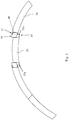
- Fig. 3 shows the segment ring 25 in a section perpendicular to the longitudinal axis 2 (for the sake of clarity without hatching), namely a section of the segment ring 25 with segments 35, 36 Joint 45, a sealing insert 46 is provided, namely a sealing plate. To receive it, a pocket 50, 51 is formed in each of the segments 35, 36 on the joint 45. (The sealing insert 46 is also shown in the section Fig. 2 to recognize.)
- the pocket 51 in the segment 36 is closed radially inwards and outwards, the sealing insert 46 is pushed in in the circumferential direction.
- the pocket 50 in the segment 35 is only closed radially inward, but open radially outward.
- the segment 36 with the sealing insert 46 is first positioned, then the segment 35 with its mutually parallel abutting edges 35a can be pushed in from the radial inside, the sealing insert 46 sliding into the pocket 50 which is open radially outward.
- the segment 35 is constructed symmetrically, that is to say has at the other end on the circumferential side a further pocket which is open radially outward.
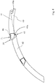
- Fig. 4 shows one to Fig. 3 alternative design of segments 40, in which case the entire segment ring 25 can be constructed from a single segment ring type.
- an abutting edge 40a of the segment 40 is inclined to a connecting line 41 in such a way that the angle ⁇ is around 90 °.
- a sealing insert 46 is arranged in one segment 40 in a radially outwardly open pocket 50 and in the other segment 40 in a radially closed pocket 51 at a respective joint 45 at which two segments 40 adjoin one another. In the latter the sealing insert 46 is positioned, then the other segment 40, as in FIG Fig. 4 shown, rotated into its mounting position.
- Turbo machine 1 compressor 1a Combustion chamber 1b turbine 1c Longitudinal axis 2 Hot gas duct 3 Shroud assembly 20th Housing part 21 Shroud segment 22nd poetry 23 Blades 24 Segment ring 25th Form-fit element 26th Edition 27 Circlip 28 recording 29 head Start 30th drilling 31 Shielding plates 32 segment 35 Abutting edge 35a segment 36 Abutting edge 36a segment 40 Abutting edge 40a Connecting line 41 Push 45 Sealing insert 46 Bags 50, 51
Landscapes
- Engineering & Computer Science (AREA)
- Mechanical Engineering (AREA)
- General Engineering & Computer Science (AREA)
- Structures Of Non-Positive Displacement Pumps (AREA)
- Turbine Rotor Nozzle Sealing (AREA)
Description
- Die vorliegende Erfindung betrifft einen Segmentring zur Montage in einer Strömungsmaschine.
- Bei der Strömungsmaschine kann es sich bspw. um ein Strahltriebwerk handeln, z. B. um ein Mantelstromtriebwerk. Funktional gliedert sich die Strömungsmaschine in Verdichter, Brennkammer und Turbine. Etwa im Falle des Strahltriebwerks wird angesaugte Luft vom Verdichter komprimiert und in der nachgelagerten Brennkammer mit hinzugemischtem Kerosin verbrannt. Das entstehende Heißgas, eine Mischung aus Verbrennungsgas und Luft, durchströmt die nachgelagerte Turbine und wird dabei expandiert. Die Turbine ist typischerweise in mehrere Module untergliedert, kann also bspw. ein Hochdruck- und ein Niederdruckturbinenmodul aufweisen. Jedes der Turbinenmodule umfasst dann in der Regel mehrere Stufen, wobei jede Stufe aus einem Leitschaufelkranz und einem stromab darauffolgenden Laufschaufelkranz aufgebaut ist.
- Der vorliegend in Rede stehende Segmentring ist zur Montage in einer Strömungsmaschine vorgesehen, bspw. in einem Turbinenmodul. Er kann bspw. an einem Gehäuseteil befestigt werden und dann ein radial innen an dem Gehäuseteil angeordnetes Mantelringsegment tragen. Ein solches Mantelringsegment begrenzt den Gaskanal auf axialer Höhe eines Laufschaufelkranzes nach außen, es kann radial innen bspw. mit einem Dichtsystem bzw. einem Einlaufbelag ausgestattet sein. Dies soll den vorliegenden Gegenstand bzw. eine bevorzugte Anwendung davon illustrieren, ihn aber zunächst nicht in seiner Allgemeinheit beschränken (der Segmentring kann in der Strömungsmaschine auch eine anderweitige Montagefunktion übernehmen).
- Ein Beispiel für einen Segmentring ist aus der
EP 1431518A2 bekannt. Ein weiteres Beispiel für einen Schaufelkranzsegmentring ist aus derWO 2012/041651 A1 bekannt. - Der vorliegenden Erfindung liegt das technische Problem zugrunde, einen besonders vorteilhaften Segmentring anzugeben.
- Dies wird erfindungsgemäß mit dem Segmentring gemäß Anspruch 1 gelöst. Dieser ist für eine Montage bzw. ein Zusammensetzen von radial innen nach außen ausgelegt und dazu umlaufend in Segmente unterteilt. An einem Stoß, an dem zwei umlaufend nächstbenachbarte Segmente aneinandergrenzen ist dabei zur Verringerung einer Leckage ein Dichteinsatz eingesetzt. Hierfür ist in den zwei Segmenten jeweils eine zu dem Stoß hin offene Tasche ausgebildet, darin sitzt der Dichteinsatz. Er ist in den Taschen axial gehalten und überbrückt den Stoß, blockiert also Spaltströmungen und erhöht die Dichtigkeit.
- Eine der einander zugewandten Taschen ist dabei ferner nicht nur zum Stoß hin, sondern auch in einer Radialrichtung offen. Dies ist hinsichtlich des radialen Zusammensetzens des Segmentrings, insbesondere vollständigen und/oder geschlossenen Segmentrings, von Vorteil, das entsprechende Segment lässt sich nämlich radial auf den Dichteinsatz aufschieben, insbesondere ohne dass für das Aufschieben eine gleichzeitige Verschiebung in einer nicht-radialen Richtung und/oder in axialer Richtung erforderlich wäre und/oder insbesondere zum Bereitstellen des vollständigen und/oder geschlossenen Segmentrings. Die Segmentierung und der Zusammenbau von radial innen eröffnen einerseits interessante Montagemöglichkeiten, indem dabei andererseits ein sich zwischen zwei Segmenten ergebender Stoß zusätzlich abgedichtet wird, kann eine etwaige Leckage gleichwohl begrenzt werden. Durch die erfindungsgemäße Ausgestaltung der Taschen lässt sich der Stoß mit einem Dichteinsatz verschließen, was eine effiziente Abdichtung bietet, es bleibt jedoch die Montage von radial innen möglich.
- Bevorzugte Ausgestaltungen finden sich in den abhängigen Ansprüchen und der gesamten Offenbarung, wobei in der Darstellung der Merkmale nicht immer im Einzelnen zwischen Vorrichtungs- und Verfahrens- bzw. Verwendungsaspekten unterschieden wird; jedenfalls implizit ist die Offenbarung hinsichtlich sämtlicher Anspruchskategorien zu lesen. Sie ist insbesondere stets auf sowohl den Segmentring als auch eine Anordnung bzw. ein Modul mit einem solchen Segmentring zu lesen, sowie auch auf entsprechende Verwendungen.
- Generell bezieht sich im Rahmen dieser Offenbarung "axial" auf die Ringachse des Segmentrings. In montiertem Zustand, also in der Strömungsmaschine bzw. einem Modul davon, fällt die Ringachse typischerweise mit der Längsachse der Strömungsmaschine bzw. der Drehachse zusammen, um welche die Laufschaufelkränze rotieren. "Radial" betrifft die zu der Ring- bzw. Längsachse senkrechten, davon wegweisenden Radialrichtungen, und ein "Umlauf" bzw. "umlaufend" oder die "Umlaufrichtung" betreffen die Drehung um die Achse. "Vorne" und "hinten" beziehen sich auf die axiale Strömungsrichtungskomponente des Heißgases, dieses passiert also "vordere" Teile axial vor "hinteren" Teilen. "Ein" und "eine" sind im Rahmen dieser Offenbarung ohne ausdrücklich gegenteilige Angabe als unbestimmte Artikel und damit immer auch als "mindestens ein" bzw. "mindestens eine" zu lesen. Es wird vorrangig auf "einen" Stoß und die dort radial geöffnete Tasche Bezug genommen. Insgesamt gibt es umlaufend eine Mehr- bzw. Vielzahl Stöße, wobei bevorzugt an jedem davon ein Dichteinsatz angeordnet ist. Dies ließe sich prinzipiell auch mit Taschen erreichen, die an den übrigen Stößen nur umlaufend geöffnet sind (das Segment mit der radial geöffneten Tasche wird zuletzt platziert), bevorzugt sind jedoch sämtliche Dichteinsätze des Segmentrings jeweils in einer radial geöffneten Tasche angeordnet.
- Der Segmentring bzw. dessen Segmente können bspw. durch Drehen und Fräsen aus einem Schmiedering hergestellt werden. Die Segmente können aber auch Gussteile sein (in Verbindung mit einer Nachbearbeitung der Funktionsflächen). Schließlich ist auch eine generative Herstellung möglich, kann der Segmentring bzw. können die Segmente also additiv Schicht für Schicht aus einem zuvor formlosen bzw. -neutralen Werkstoff aufgebaut werden. Die Taschen können bereits bei der originären Formgebung berücksichtigt werden, sie lassen sich aber ebenso materialabtragend einbringen, bspw. erodieren (Funkenerodieren).
- Aufgrund der radial geöffneten Tasche lässt sich das entsprechende Segment radial auf den Dichteinsatz aufschieben. Die Tasche ist hierfür in der Einsetzrichtung ausgerichtet, in welcher das bzw. die Segmente zusammengesetzt werden. Die Einsetzrichtung kann im Allgemeinen auch einen axialen Anteil haben (bspw. in einem Axialschnitt betrachtet um nicht mehr als 30° zur Radialrichtung verkippt liegen), bevorzugt liegt sie senkrecht zur Axialrichtung. Die radial offene Tasche kann prinzipiell auch nach radial innen geöffnet sein (und nach radial außen geschlossen); bei der Montage würde dann dieses Segment zuerst und anschließend das andere Segment zusammen mit dem Dichteinsatz platziert werden, der hierbei in dessen geschlossener Tasche angeordnet wäre und in die nach radial innen offene Tasche rutschen würde.
- In bevorzugter Ausgestaltung ist die radial offene Tasche jedoch nach radial außen offen und nach radial innen geschlossen. Das Segment mit dieser Tasche kann entsprechend von radial innen auf den Dichteinsatz aufgeschoben werden, der hierbei bereits in der Tasche des anderen Segments positioniert ist. Im montierten Zustand ist der Dichteinsatz dann, im Unterschied zu einer nach radial innen offenen Tasche, in beiden Taschen gegen ein Herausfallen nach innen und außen gesichert, da die offene Tasche gegen die Gehäusewand gerichtet ist.
- Die radial geschlossene Tasche ist in bevorzugter Ausgestaltung nach radial innen und nach radial außen geschlossen. Vorzugsweise ist also die radial offene Tasche in genau einer Radialrichtung geöffnet, bevorzugt nach radial außen, und ist die andere Tasche in beiden Radialrichtungen geschlossen. Der Dichteinsatz ist somit bereits vor dem Zusammensetzen der Segmente in der geschlossenen Tasche weitgehend verliersicher gehalten. Zum Schutz gegen ein Herausfallen kann bei der Montage auch generell ein Fett verwendet werden, das den Dichteinsatz wie ein Klebstoff hält. Auch mit Blick hierauf ist die geschlossene Tasche bei einer bevorzugten Ausführungsform derart bemessen, dass ihre senkrecht zu dem Stoß genommene Tiefe mindestens dem 0,1-fachen ihrer parallel zu dem Stoß genommenen Höhe entspricht. Die Tasche ist dahingehend bemessen, dass sich der Dichteinsatz vor dem Zusammensetzen der Segmente nicht herausdrehen kann. Weitere bevorzugte Untergrenzen der Tiefe liegen bei mindestens dem 0,2-, 0,3- bzw. 0,4-fachen der Höhe, mit möglichen (davon unabhängigen) Obergrenzen bei z. B. höchstens dem 2-, 1,5-, 1- bzw. 0,8-fachen der Höhe.
- In bevorzugter Ausgestaltung ist der Dichteinsatz ein Dichtblech.
- Vorzugsweise dichtet der Dichteinsatz, insbesondere das Dichtblech, das beispielsweise ein planares Dichtblech ist, den Stoß und/oder einen Segmentspalt zwischen den umlaufend nächstbenachbarten Segmenten in axialer Richtung ab. Im Falle eines planaren Dichtblechs liegt die axialer Richtung vorzugsweise normal zur Blechebene oder im Wesentlichen normal zu dieser, d.h. mit einer maximalen Abweichung von 10°, insbesondere 5°, zur exakt normalen Orientierung.
- Bei einer bevorzugten Ausführungsform ist ein Sicherungsring vorgesehen, an dem die Segmente des Segmentrings nach radial innen abgestützt aufsitzen. Dazu kann sich der Sicherungsring in Umlaufrichtung unterbrechungsfrei erstrecken. Bevorzugt ist der Sicherungsring axial in eine Aufnahme in dem Segmentring eingepresst und durch einen Presssitz gehalten. Vorzugsweise bildet der Segmentring an der Aufnahme einen radial hervortretenden Vorsprung, hinter dem der Sicherungsring axial formschlüssig gehalten ist. Der Vorsprung ist derart bemessen, dass der Sicherungsring axial eingepresst werden kann, dann aber axial entgegengesetzt gesichert ist. Bevorzugt wird dies durch eine schräg angestellte Flanke (Sägezahnprofil) unterstützt, entlang welcher der Sicherungsring beim Einpressen rutscht.
- Die im Folgenden geschilderten Ausführungsformen betreffen die Orientierung bzw. Erstreckung der Stoßkanten, mit welchen die Segmente des Segmentrings in einem jeweiligen Stoß aneinandergrenzen. Zwei umlaufend nächstbenachbarte Segmente haben an dem jeweiligen Stoß zueinander komplementäre Stoßkanten.
- Bei einer bevorzugten Ausführungsform hat jeweils eines von zwei aneinandergrenzenden Segmenten Stoßkanten, die zueinander und damit zu einer Einsetzrichtung dieses Segments parallel sind (in axialer Richtung gesehen). Ein solches Segment lässt sich nach radial außen einschieben, auch wenn die beiden umlaufend nächstbenachbarten Segmente bereits positioniert sind. Bezogen auf den Segmentring im Gesamten sind die zueinander parallelen Stoßkanten bevorzugt derart orientiert, dass sie bzw. ihre Verlängerungen zur gegenüberliegenden Seite des Segmentrings hin dessen Ringachse mittig einfassen.
- In bevorzugter Ausgestaltung weist ein solches Segment mit zueinander parallelen Stoßkanten an beiden Umlaufseiten jeweils eine Tasche mit jeweils einem Dichteinsatz darin auf. Bevorzugt sind diese beiden Taschen jeweils nach radial außen offen und nach radial innen geschlossen. Vorzugsweise hat in Umlaufrichtung jedes zweite Segment jeweils für sich zueinander parallele Stoßkanten. Bevorzugt sind diese Segmente untereinander baugleich und sind auch die dazwischen angeordneten, komplementären Segmente untereinander baugleich, sodass der gesamte Segmentring mit nur zwei unterschiedlichen Segmenttypen aufgebaut werden kann.
- Bei einer anderen bevorzugten Ausführungsform ist bzw. sind die Segmente derart gefasst, dass der Segmentring im Idealfall aus sogar nur einem einzigen Segmentringtyp aufgebaut werden kann. Dazu hat eines der an dem Stoß aneinandergrenzenden Segmente dort eine zur Radialrichtung schräge Stoßkante. Konkret schließt die schräge Stoßkante mit einer Verbindungslinie, die sich diagonal durch das Segment zur äußeren Ecke der schrägen Stoßkante erstreckt, einen Winkel α von mindestens 85° und höchstens 110° ein. Weitere bevorzugte Obergrenzen liegen bei höchstens 100° bzw. 95°, weitere bevorzugte Untergrenzen liegen (davon unabhängig) bei mindestens 88° bzw. 90° (jeweils in der Reihenfolge der Nennung zunehmend bevorzugt). Durch eine entsprechende Begrenzung des Winkels α lässt sich das Segment auch dann einsetzen, wenn die umlaufend nächstbenachbarten Segmente bereits in ihrer Montageposition angeordnet sind. Das Segment kann hierbei zunächst mit der entgegengesetzten Stoßkante in Position gebracht und dann gewissermaßen in eine Anlage mit der schrägen Stoßkante hineingedreht werden, vgl.
Figur 4 zur Illustration. - In bevorzugter Ausgestaltung ist das Segment an dieser schrägen Stoßkante mit der nach radial außen offenen (und nach radial innen geschlossenen) Tasche ausgestattet. Ein solches Segment kann, wie im vorherigen Absatz geschildert, zunächst mit der entgegengesetzten Stoßkante eingehängt und dann in seine Montageposition hineingedreht werden, wobei der Dichteinsatz in die nach radial außen offene Tasche des Segments rutscht. Vorzugsweise sind sämtliche Segmente baugleich, also drehsymmetrisch um die Ring- bzw. Längsachse. Die Handhabung von nur einem einzigen Segmentringtyp kann die Montage und die Lagerhaltung vereinfachen.
- Die Erfindung betrifft auch eine Segmentringanordnung mit einem vorliegend offenbarten Segmentring und einem Montageteil, vorzugsweise einem Gehäuseteil. Der Segmentring wird bzw. ist an dem Montageteil, konkret einem Formschlusselement davon, axial formschlüssig montiert. Dazu sind die einzelnen Segmente jeweils nach radial außen mit dem Formschlusselement zusammengesetzt. Vorzugsweise ist radial innen an dem Gehäuseteil ein Mantelringsegment montiert, vergleiche auch die Anmerkungen eingangs. Der Segmentring dient hierbei der Montage des Mantelringsegments; der Segmentring wird an dem Gehäuseteil montiert, und das Mantelringsegment liegt dann nach radial innen abgestützt darauf. Dieser Aufbau kann hinsichtlich der Thermalgradienten von Vorteil sein (insbesondere im Gehäusebereich), und zudem ist eine Montage bzw. Demontage von axial vorne möglich.
- Die Erfindung betrifft auch ein Turbinenmodul mit einer solchen Segmentringanordnung, wobei radial innerhalb des Mantelringsegments ein Laufschaufelkranz angeordnet ist. Bevorzugt ist die Segmentringanordnung am axial vorderen Ende des Turbinenmoduls vorgesehen. Im Zuge einer Überholung lassen sich die Module einerseits vergleichsweise einfach voneinander trennen, sie sind dann also jeweils auch von axial vorne zugänglich; anderseits können die axial vorne angeordneten Bauteile auch besonders belastet und damit überholungsbedürftig sein.
- Die Erfindung betrifft auch die Verwendung eines Turbinenmoduls bzw. eines Segmentrings oder einer entsprechenden Segmentringanordnung in einer Strömungsmaschine, insbesondere in einem Strahltriebwerk, bspw. einem Mantelstromtriebwerk.
- Im Folgenden wird die Erfindung anhand eines Ausführungsbeispiels näher erläutert, wobei die einzelnen Merkmale im Rahmen der nebengeordneten Ansprüche auch in anderer Kombination erfindungswesentlich sein können und auch weiterhin nicht im Einzelnen zwischen den unterschiedlichen Anspruchskategorien unterschieden wird.
- Im Einzelnen zeigt
- Figur 1
- ein Mantelstromtriebwerk in einem Axialschnitt;
- Figur 2
- eine erfindungsgemäße Mantelringanordnung als Teil des Mantelstromtriebwerks gemäß
Figur 1 in einem Axialschnitt; - Figur 3
- einen Ausschnitt eines Segmentrings der Anordnung gemäß
Figur 2 in einem Schnitt senkrecht zur axialen Richtung; - Figur 4
- als Alternative zu
Figur 3 eine weitere Möglichkeit zur Orientierung der Stoßkanten der einzelnen Segmente. -
Fig. 1 zeigt eine Strömungsmaschine 1, konkret ein Mantelstromtriebwerk, in einem Axialschnitt. Die Strömungsmaschine 1 gliedert sich funktional in Verdichter 1a, Brennkammer 1b und Turbine 1c. Sowohl der Verdichter 1a als auch die Turbine 1c sind jeweils aus mehreren Stufen aufgebaut, jede Stufe setzt sich aus einem Leit- und einem darauffolgenden Laufschaufelkranz zusammen. Die Laufschaufelkränze rotieren im Betrieb um die Längsachse 2 der Strömungsmaschine 1. Im Verdichter 1a wird die angesaugte Luft komprimiert, und dann in der nachgelagerten Brennkammer 1b mit hinzugemischtem Kerosin verbrannt. Das Heißgas durchströmt den Heißgaskanal 3 und treibt dabei die Laufschaufelkränze an, die um die Längsachse 2 rotieren.Fig. 2 zeigt eine Mantelringanordnung 20, die als Teil eines Moduls der Turbine 1c vorgesehen ist. Sie weist ein Gehäuseteil 21 und ein Mantelringsegment 22 auf, an dem radial innen eine Dichtung 23 angeordnet ist, vorliegend eine Honigwabendichtung. Das Mantelringsegment 22 fasst die Laufschaufeln 24 nach radial außen ein. - Zur Montage des Mantelringsegments 22 an dem Gehäuseteil 21 ist ein Segmentring 25 vorgesehen, der in Umlaufrichtung in eine Mehrzahl Segmente untergliedert ist (vgl.
Fig. 3 und4 ). Die einzelnen Segmente des Segmentrings 25 werden von radial innen mit einem Formschlusselement 26 des Gehäuseteils 21 zusammengesetzt. Das Formschlusselement 26 ist vorliegend als nach radial innen hervortretender Gehäusesteg vorgesehen, auf den die Segmente des Segmentrings 25 aufgeschoben werden und dann axial formschlüssig gehalten sind. Der Segmentring 25 bildet eine Auflage 27, die das Mantelringsegment 22 an seinem axial vorderen Ende nach radial innen abstützt. Um die Segmente des Segmentrings 25 radial in Position zu halten, ist ein Sicherungsring 28 eingesetzt. Dieser erstreckt sich umlaufend unterbrechungsfrei und wird axial in eine Aufnahme 29 des Segmentrings 25 eingepresst. In der Aufnahme 29 ist er hinter einem Vorsprung 30 axial formschlüssig gehalten. - In dem Formschlusselement 26 bzw. dem Gehäusesteg des Gehäuseteils 21 ist eine Bohrung 31 vorgesehen, die zum Zuführen eines Kühlfluids genutzt werden kann (und optional ist). Ferner sind auch die radial zwischen dem Gehäuseteil 21 und dem Mantelringsegment 22 angeordneten Abschirmbleche 32 optional, der erfindungsgemäße Ansatz ließe sich ebenso mit einem Isoliermaterial oder dergleichen zwischen dem Gehäuseteil 21 und dem Mantelringsegment 22 realisieren.
-
Fig. 3 zeigt den Segmentring 25 in einem zur Längsachse 2 senkrechten Schnitt (der Übersichtlichkeit halber ohne Schraffur), und zwar einen Ausschnitt des Segmentrings 25 mit Segmenten 35, 36. Die zwei umlaufend nächstbenachbarten Segmente 35, 36 grenzen in einem Stoß 45 aneinander, zur Abdichtung des Stoßes 45 ist ein Dichteinsatz 46 vorgesehen, nämlich ein Dichtblech. Für dessen Aufnahme ist in jedem der Segmente 35, 36 an dem Stoß 45 jeweils eine Tasche 50,51 ausgebildet. (Der Dichteinsatz 46 ist auch in dem Schnitt gemäßFig. 2 zu erkennen.) - Die Tasche 51 in dem Segment 36 ist nach radial innen und außen geschlossen, der Dichteinsatz 46 wird in Umlaufrichtung eingeschoben. Die Tasche 50 in dem Segment 35 ist hingegen nur nach radial innen geschlossen, nach radial außen jedoch offen. Bei der Montage wird zunächst das Segment 36 mit dem Dichteinsatz 46 positioniert, anschließend kann das Segment 35 mit seinen zueinander parallelen Stoßkanten 35a von radial innen eingeschoben werden, wobei der Dichteinsatz 46 in die nach radial außen offene Tasche 50 rutscht. Das Segment 35 ist symmetrisch aufgebaut, weist also am anderen umlaufseitigen Ende eine weitere nach radial außen offene Tasche auf.
-
Fig. 4 zeigt eine zuFig. 3 alternative Gestaltung von Segmenten 40, wobei in diesem Fall der gesamte Segmentring 25 aus einem einzigen Segmentringtyp aufgebaut werden kann. Dazu liegt eine Stoßkante 40a des Segments 40 derart schräg zu einer Verbindungslinie 41, dass der Winkel α rund 90° beträgt. Auch in diesem Fall ist an einem jeweiligen Stoß 45, an dem zwei Segmente 40 aneinandergrenzen, ein Dichteinsatz 46 in dem einen Segment 40 in einer nach radial außen offenen Tasche 50 angeordnet und in dem anderen Segment 40 in einer radial geschlossenen Tasche 51. In letzterer wird der Dichteinsatz 46 positioniert, anschließend wird das andere Segment 40, wie inFig. 4 dargestellt, in seine Montageposition hineingedreht. -
Strömungsmaschine 1 Verdichter 1a Brennkammer 1b Turbine 1c Längsachse 2 Heißgaskanal 3 Mantelringanordnung 20 Gehäuseteil 21 Mantelringsegment 22 Dichtung 23 Laufschaufeln 24 Segmentring 25 Formschlusselement 26 Auflage 27 Sicherungsring 28 Aufnahme 29 Vorsprung 30 Bohrung 31 Abschirmbleche 32 Segment 35 Stoßkante 35a Segment 36 Stoßkante 36a Segment 40 Stoßkante 40a Verbindungslinie 41 Stoß 45 Dichteinsatz 46 Taschen 50, 51
Claims (15)
- Segmentring (25) zur Montage in einer Strömungsmaschine (1),
der, bezogen auf eine Ringachse des Segmentrings (25), umlaufend in Segmente (35, 36, 40) unterteilt ist, dadurch gekennzeichnet, dass der Segmentring (25) für eine Montage von radial innen ausgelegt ist, die Segmente (35, 36, 40) also nach radial außen zu dem Segmentring (25) zusammensetzbar sind,
wobei zumindest zwei umlaufend nächstbenachbarte Segmente (35, 36, 40) in einem Stoß (45) aneinandergrenzen, an dem ein Dichteinsatz (46) vorgesehen ist,
wozu in den zumindest zwei umlaufend nächstbenachbarten Segmenten (35, 36, 40) jeweils eine zu dem Stoß (45) hin offene Tasche (50, 51) ausgebildet ist, an dem Stoß (45) also zwei umlaufend einander zugewandte Taschen (50, 51) vorgesehen sind,
wobei der Dichteinsatz (46) in den zwei einander zugewandten Taschen (50, 51) angeordnet und darin axial gehalten ist und sich dabei umlaufend über den Stoß (45) hinweg erstreckt,
und wobei eine (50) der zwei einander zugewandten Taschen (50, 51) zusätzlich auch in einer Radialrichtung derart offen ist, dass dieses Segment (35, 40) radial auf den Dichteinsatz (46) aufgeschoben werden kann. - Segmentring (25) nach Anspruch 1, bei welchem die radial offene Tasche (50) nach radial innen geschlossen und nach radial außen offen ist, dieses Segment (35, 40) also von radial innen auf den Dichteinsatz (46) aufgeschoben werden kann.
- Segmentring (25) nach Anspruch 1 oder 2, bei welchem die andere (51) der zwei einander zugewandten Taschen (50, 51) nach radial innen und radial außen geschlossen ist.
- Segmentring (25) nach Anspruch 3, bei welchem die nach radial innen und radial außen geschlossene Tasche (51) eine senkrecht zu dem Stoß (45) genommene Tiefe hat, die mindestens dem 0,1 -fachen ihrer parallel zu dem Stoß (45) genommen Höhe entspricht.
- Segmentring (25) nach einem der vorstehenden Ansprüche, bei welchem der Dichteinsatz (46) ein Dichtblech ist und/oder bei welchem der Dichteinsatz (46) den Stoß (45) in axialer Richtung abdichtet.
- Segmentring (25) nach einem der vorstehenden Ansprüche mit einem Sicherungsring (28), an dem die Segmente (35, 36, 40) nach radial innen abgestützt aufsitzen.
- Segmentring (25) nach einem der vorstehenden Ansprüche, bei welchem eines (35) der zwei aneinandergrenzenden Segmente (35, 36) an dem Stoß (45) und umlaufend entgegengesetzt jeweils eine Stoßkante (35a) hat und diese Stoßkanten (35a) in axialer Richtung gesehen parallel zueinander liegen.
- Segmentring (25) nach den Ansprüchen 2 und 7, bei welchem die nach radial innen geschlossene und nach radial außen offene Tasche (50) in dem Segment (35) mit den zueinander parallelen Stoßkanten (35a) vorgesehen ist, wobei in diesem Segment (35) auch umlaufend entgegengesetzt eine nach radial innen geschlossene und nach radial außen offene Tasche vorgesehen ist, in welcher ein weiterer Dichteinsatz (46) angeordnet ist.
- Segmentring (25) nach einem der Ansprüche 1 bis 6, bei welchem eines der zwei aneinandergrenzenden Segmente (40) an dem Stoß (45) eine schräge Stoßkante (40a) hat, die in axialer Richtung gesehen mit einer Verbindungslinie (41), die sich zwischen einem Schnittpunkt der schrägen Stoßkante (40a) mit einer Außenumfangslinie des Segmentrings (25) und einem Schnittpunkt einer entgegengesetzten Stoßkante dieses Segments mit einer Innenumfangslinie des Segmentrings (25) erstreckt, einen Winkel α einschließt, der mindestens 85° und höchstens 110° beträgt.
- Segmentring (25) nach den Ansprüchen 2 und 9, bei welchem die Tasche (50), die an dem Stoß (45) der zwei aneinandergrenzenden Segmente (40) nach radial innen geschlossen und nach radial außen offen ist, an der schrägen Stoßkante (40a) angeordnet ist, also in dem Segment (40) mit der an dem Stoß (45) schrägen Stoßkante (40a).
- Segmentring (25) nach Anspruch 9 oder 10, bei welchem sämtliche Segmente (40) des Segmentrings (25) zueinander baugleich sind.
- Segmentringanordnung für eine Strömungsmaschine (1), mit einem Segmentring (25) nach einem der vorstehenden Ansprüche und einem Montageteil mit einem Formschlusselement (26), an dem der Segmentring (25) axial formschlüssig angeordnet ist,
wozu die Segmente (35, 36, 40) des Segmentrings (25) jeweils nach radial außen mit dem Formschlusselement (26) zusammengesetzt sind. - Segmentringanordnung nach Anspruch 12 mit einem Mantelringsegment (22), das dazu vorgesehen ist, einen Laufschaufelkranz der Strömungsmaschine (1) nach radial außen einzufassen, wobei das Montageteil, an dem der Segmentring (25) axial formschlüssig montiert ist, ein Gehäuseteil (21) ist, und wobei das Mantelringsegment (22) radial innerhalb des Gehäuseteils (21) montiert ist, indem der Segmentring (25) eine Auflage (27) bildet, auf welcher das Mantelringsegment (22) mit einem axial vorderen Ende nach radial innen abgestützt aufsitzt.
- Turbinenmodul mit einer Segmentringanordnung nach Anspruch 13 und mit einem Laufschaufelkranz, den das Mantelringsegment (22) nach radial außen einfasst, wobei die Segmentringanordnung und damit der Segmentring (25) bevorzugt an einem axial vorderen Ende des Turbinenmoduls angeordnet sind.
- Verwendung eines Segmentrings (25) nach einem der Ansprüche 1 bis 11, einer Segmentringanordnung nach Anspruch 12 oder 13 oder eines Turbinenmoduls gemäß Anspruch 14 in einer Strömungsmaschine (1), insbesondere in einem Strahltriebwerk.
Applications Claiming Priority (1)
| Application Number | Priority Date | Filing Date | Title |
|---|---|---|---|
| DE102018210601.0A DE102018210601A1 (de) | 2018-06-28 | 2018-06-28 | Segmentring zur montage in einer strömungsmaschine |
Publications (2)
| Publication Number | Publication Date |
|---|---|
| EP3587741A1 EP3587741A1 (de) | 2020-01-01 |
| EP3587741B1 true EP3587741B1 (de) | 2021-08-11 |
Family
ID=67105798
Family Applications (1)
| Application Number | Title | Priority Date | Filing Date |
|---|---|---|---|
| EP19182753.4A Active EP3587741B1 (de) | 2018-06-28 | 2019-06-27 | Segmentring zur montage in einer strömungsmaschine |
Country Status (4)
| Country | Link |
|---|---|
| US (1) | US11125097B2 (de) |
| EP (1) | EP3587741B1 (de) |
| DE (1) | DE102018210601A1 (de) |
| ES (1) | ES2887231T3 (de) |
Families Citing this family (1)
| Publication number | Priority date | Publication date | Assignee | Title |
|---|---|---|---|---|
| CN113898420A (zh) * | 2021-10-10 | 2022-01-07 | 中国航发沈阳发动机研究所 | 一种压气机静子内环及其静子结构 |
Family Cites Families (111)
| Publication number | Priority date | Publication date | Assignee | Title |
|---|---|---|---|---|
| USRE21272E (en) * | 1939-11-21 | hallerberg | ||
| BE514728A (de) * | 1951-10-10 | |||
| GB750397A (en) * | 1951-12-10 | 1956-06-13 | Power Jets Res & Dev Ltd | Damped turbine and dynamic compressor blades |
| US2835515A (en) * | 1955-12-05 | 1958-05-20 | Crane Packing Co | Rotary mechanical seal with self-locking seat |
| US3303992A (en) * | 1965-03-03 | 1967-02-14 | Gen Motors Corp | Variable vane stator ring |
| US3487879A (en) * | 1967-08-02 | 1970-01-06 | Dowty Rotol Ltd | Blades,suitable for propellers,compressors,fans and the like |
| US3728041A (en) * | 1971-10-04 | 1973-04-17 | Gen Electric | Fluidic seal for segmented nozzle diaphragm |
| GB1387866A (en) * | 1972-06-21 | 1975-03-19 | Rolls Royce | Aerofoil members for gas turbine engines |
| JPS5421900B2 (de) * | 1973-02-15 | 1979-08-02 | ||
| US3870434A (en) * | 1973-12-21 | 1975-03-11 | Gen Electric | Gear arrangement for variable pitch fan |
| US3887297A (en) * | 1974-06-25 | 1975-06-03 | United Aircraft Corp | Variable leading edge stator vane assembly |
| US4047840A (en) * | 1975-05-29 | 1977-09-13 | The United States Of America As Represented By The Administrator Of The National Aeronautics And Space Administration | Impact absorbing blade mounts for variable pitch blades |
| US3970318A (en) * | 1975-09-26 | 1976-07-20 | General Electric Company | Sealing means for a segmented ring |
| US4395195A (en) * | 1980-05-16 | 1983-07-26 | United Technologies Corporation | Shroud ring for use in a gas turbine engine |
| US4363600A (en) * | 1981-04-06 | 1982-12-14 | General Motors Corporation | Variable vane mounting |
| FR2524934B1 (fr) * | 1982-04-08 | 1986-12-26 | Snecma | Dispositif de butee de securite pour pivot d'aubes de stator a calage variable |
| US4498790A (en) * | 1983-11-21 | 1985-02-12 | United Technologies Corporation | Bushing securing apparatus |
| FR2556410B1 (fr) * | 1983-12-07 | 1986-09-12 | Snecma | Dispositif de centrage de l'anneau interieur d'un stator a ailettes a calage variable |
| FR2582720B1 (fr) * | 1985-05-29 | 1989-06-02 | Snecma | Procede de realisation de pivot d'aube de turbomachine et aube de stator le comportant |
| DE3718678A1 (de) * | 1987-06-04 | 1988-12-22 | Mtu Muenchen Gmbh | Fasertechnische verdichterschaufel |
| GB2210935B (en) * | 1987-10-10 | 1992-05-27 | Rolls Royce Plc | Variable stator vane assembly |
| US4834613A (en) * | 1988-02-26 | 1989-05-30 | United Technologies Corporation | Radially constrained variable vane shroud |
| US5102302A (en) * | 1988-06-02 | 1992-04-07 | General Electric Company | Fan blade mount |
| US4897021A (en) * | 1988-06-02 | 1990-01-30 | United Technologies Corporation | Stator vane asssembly for an axial flow rotary machine |
| US5165856A (en) * | 1988-06-02 | 1992-11-24 | General Electric Company | Fan blade mount |
| US5022824A (en) * | 1988-10-07 | 1991-06-11 | United Technologies Corporation | Pinned airfoil propeller blade |
| US4990056A (en) * | 1989-11-16 | 1991-02-05 | General Motors Corporation | Stator vane stage in axial flow compressor |
| US5205714A (en) * | 1990-07-30 | 1993-04-27 | General Electric Company | Aircraft fan blade damping apparatus |
| IE67360B1 (en) * | 1990-09-25 | 1996-03-20 | United Technologies Corp | Apparatus and method for a stator assembly of a rotary machine |
| US5259728A (en) * | 1992-05-08 | 1993-11-09 | General Electric Company | Bladed disk assembly |
| FR2691507B1 (fr) * | 1992-05-20 | 1994-07-08 | Snecma | Structure d'etancheite pour une aube pivotante de turbomachine. |
| USD341145S (en) * | 1992-09-14 | 1993-11-09 | Esworthy S James | Bushing |
| DE59205187D1 (de) * | 1992-10-05 | 1996-03-07 | Asea Brown Boveri | Leitschaufeleinhängung für axialdurchströmte Turbomaschine |
| US5517817A (en) * | 1993-10-28 | 1996-05-21 | General Electric Company | Variable area turbine nozzle for turbine engines |
| FR2723614B1 (fr) * | 1994-08-10 | 1996-09-13 | Snecma | Dispositif d'assemblage d'un etage circulaire d'aubes pivotantes. |
| US5653580A (en) * | 1995-03-06 | 1997-08-05 | Solar Turbines Incorporated | Nozzle and shroud assembly mounting structure |
| FR2742799B1 (fr) * | 1995-12-20 | 1998-01-16 | Snecma | Palier d'extremite interne d'aube pivotante |
| US7059827B1 (en) * | 1996-05-31 | 2006-06-13 | Watson Cogeneration Company | Turbine power plant having minimal-contact brush seal augmented labyrinth seal |
| US5664536A (en) * | 1996-08-14 | 1997-09-09 | Brunswick Corporation | Self-locating piston ring for a two-stroke engine |
| US6318728B1 (en) * | 1997-07-11 | 2001-11-20 | Demag Delaval Turbomachinery Corporation | Brush-seal designs for elastic fluid turbines |
| FR2775731B1 (fr) * | 1998-03-05 | 2000-04-07 | Snecma | Etage circulaire d'aubes aux extremites interieures unies par un anneau de liaison |
| US6086327A (en) * | 1999-01-20 | 2000-07-11 | Mack Plastics Corporation | Bushing for a jet engine vane |
| US6257593B1 (en) * | 1999-05-14 | 2001-07-10 | Patrick Michel White | Stress induced interposed connector |
| US6435519B1 (en) * | 1999-05-14 | 2002-08-20 | Patrick Michel White | Stress-induced gasket |
| US6550779B2 (en) * | 1999-07-27 | 2003-04-22 | Northeast Equipment, Inc. | Mechanical split seal |
| US6637995B1 (en) * | 2000-02-09 | 2003-10-28 | Patrick Michel White | Super-elastic rivet assembly |
| US6457721B1 (en) * | 2001-01-26 | 2002-10-01 | White Consolidated Industries, Inc. | Piston ring locator |
| US6481960B2 (en) * | 2001-03-30 | 2002-11-19 | General Electric Co. | Variable gas turbine compressor vane structure with sintered-and-infiltrated bushing and washer bearings |
| US6682299B2 (en) * | 2001-11-15 | 2004-01-27 | General Electric Company | Variable stator vane support arrangement |
| DE10161292A1 (de) * | 2001-12-13 | 2003-06-26 | Rolls Royce Deutschland | Lagerring zur Lagerung von Schaufelfüßen von verstellbaren Statorschaufeln im Hochdruckverdichter einer Gasturbine |
| USD517900S1 (en) * | 2002-04-04 | 2006-03-28 | 420820 Ontario Limited | Bushing |
| US6733233B2 (en) * | 2002-04-26 | 2004-05-11 | Pratt & Whitney Canada Corp. | Attachment of a ceramic shroud in a metal housing |
| US6877952B2 (en) * | 2002-09-09 | 2005-04-12 | Florida Turbine Technologies, Inc | Passive clearance control |
| US6893214B2 (en) | 2002-12-20 | 2005-05-17 | General Electric Company | Shroud segment and assembly with surface recessed seal bridging adjacent members |
| US6808363B2 (en) | 2002-12-20 | 2004-10-26 | General Electric Company | Shroud segment and assembly with circumferential seal at a planar segment surface |
| US7360990B2 (en) * | 2004-10-13 | 2008-04-22 | General Electric Company | Methods and apparatus for assembling gas turbine engines |
| FR2882578B1 (fr) * | 2005-02-25 | 2007-05-25 | Snecma Moteurs Sa | Dispositif de reglage du centrage d'un anneau de synchronisation de commande d'aubes pivotantes de turbomachine |
| US7334980B2 (en) * | 2005-03-28 | 2008-02-26 | United Technologies Corporation | Split ring retainer for turbine outer air seal |
| FR2889242B1 (fr) * | 2005-07-27 | 2007-11-02 | Snecma | Douille pour pivot d'aube a angle de calage variable pour turbomachine |
| US7510369B2 (en) * | 2005-09-02 | 2009-03-31 | United Technologies Corporation | Sacrificial inner shroud liners for gas turbine engines |
| FR2890707B1 (fr) * | 2005-09-14 | 2007-12-14 | Snecma | Douille pour pivot d'aube a angle de calage variable pour turbomachine |
| US7427187B2 (en) * | 2006-01-13 | 2008-09-23 | General Electric Company | Welded nozzle assembly for a steam turbine and methods of assembly |
| FR2902822B1 (fr) * | 2006-06-21 | 2008-08-22 | Snecma Sa | Palier pour aube de stator a calage variable |
| US20080044284A1 (en) * | 2006-08-16 | 2008-02-21 | United Technologies Corporation | Segmented fluid seal assembly |
| US9353643B2 (en) * | 2007-04-10 | 2016-05-31 | United Technologies Corporation | Variable stator vane assembly for a turbine engine |
| USD681512S1 (en) * | 2009-05-19 | 2013-05-07 | Larry John Verbowski | Suspension module |
| US8328512B2 (en) * | 2009-06-05 | 2012-12-11 | United Technologies Corporation | Inner diameter shroud assembly for variable inlet guide vane structure in a gas turbine engine |
| US8448993B2 (en) * | 2009-06-12 | 2013-05-28 | Romac Industries, Inc. | Pipe coupling |
| US8622693B2 (en) * | 2009-08-18 | 2014-01-07 | Pratt & Whitney Canada Corp | Blade outer air seal support cooling air distribution system |
| EP2336572B1 (de) * | 2009-12-14 | 2012-07-25 | Techspace Aero S.A. | Zweiteiliges Gehäuse für einen Stromdiffusor eines Axialkompressors |
| US8491267B2 (en) * | 2010-08-27 | 2013-07-23 | Pratt & Whitney Canada Corp. | Retaining ring arrangement for a rotary assembly |
| DE102010041808B4 (de) * | 2010-09-30 | 2014-10-23 | Siemens Aktiengesellschaft | Schaufelkranzsegment, Strömungsmaschine sowie Verfahren zu deren Herstellung |
| US8770930B2 (en) * | 2011-02-09 | 2014-07-08 | Siemens Energy, Inc. | Joining mechanism and method for interlocking modular turbine engine component with a split ring |
| DE102012005771B4 (de) * | 2011-03-25 | 2022-06-30 | General Electric Technology Gmbh | Dichtvorrichtung für drehende Turbinenschaufeln |
| EP2520769A1 (de) * | 2011-05-02 | 2012-11-07 | MTU Aero Engines GmbH | Innenring zur Bildung eines Leitschaufelkranzes, Leitschaufelkranz und Strömungsmaschine |
| US20120319360A1 (en) * | 2011-06-20 | 2012-12-20 | Blaney Ken F | Plug assembly for blade outer air seal |
| EP2644833A1 (de) * | 2012-03-26 | 2013-10-02 | Alstom Technology Ltd | Trägerring |
| WO2014089642A1 (en) * | 2012-12-11 | 2014-06-19 | Rotacaster Wheel Limited | Axel bush |
| US9932988B2 (en) * | 2013-02-15 | 2018-04-03 | United Technologies Corporation | Bushing arranged between a body and a shaft, and connected to the shaft |
| US9500095B2 (en) * | 2013-03-13 | 2016-11-22 | Pratt & Whitney Canada Corp. | Turbine shroud segment sealing |
| FR3009335B1 (fr) * | 2013-07-30 | 2015-09-04 | Snecma | Dispositif de guidage d'aubes de redresseur a angle de calage variable de turbomachine |
| WO2015031058A1 (en) * | 2013-08-28 | 2015-03-05 | United Technologies Corporation | Variable vane bushing |
| ES2935815T3 (es) * | 2013-09-06 | 2023-03-10 | MTU Aero Engines AG | (Des)montaje de un rotor de una turbina de gas, en particular delantero |
| EP2857639A1 (de) | 2013-10-01 | 2015-04-08 | Siemens Aktiengesellschaft | Dichtungsring |
| US9546559B2 (en) * | 2013-10-08 | 2017-01-17 | General Electric Company | Lock link mechanism for turbine vanes |
| EP3071794B8 (de) * | 2013-11-19 | 2021-04-07 | Raytheon Technologies Corporation | Mehrteilige innendeckbandverlängerung für eine turbomaschine |
| FR3014152B1 (fr) * | 2013-11-29 | 2015-12-25 | Snecma | Dispositif de guidage d'aubes de redresseur a angle de calage variable de turbomachine et procede d'assemblage d'un tel dispositif |
| JP6118721B2 (ja) * | 2013-12-20 | 2017-04-19 | 株式会社Ihi | ファンケース及びファンケースの製造方法 |
| FR3019597B1 (fr) * | 2014-04-08 | 2016-03-25 | Turbomeca | Compresseur de turbomachine a aubes a calage variable |
| US10088049B2 (en) * | 2014-05-06 | 2018-10-02 | United Technologies Corporation | Thermally protected seal assembly |
| DE102014209057A1 (de) * | 2014-05-14 | 2015-11-19 | MTU Aero Engines AG | Gasturbinengehäuseanordnung |
| GB201419965D0 (en) * | 2014-10-06 | 2014-12-24 | Rolls Royce Plc | Fan |
| US10184356B2 (en) * | 2014-11-25 | 2019-01-22 | United Technologies Corporation | Blade outer air seal support structure |
| US10370998B2 (en) * | 2015-05-26 | 2019-08-06 | Rolls-Royce Corporation | Flexibly mounted ceramic matrix composite seal segments |
| US11156117B2 (en) | 2016-04-25 | 2021-10-26 | Raytheon Technologies Corporation | Seal arc segment with sloped circumferential sides |
| FR3051174B1 (fr) * | 2016-05-10 | 2018-06-01 | Safran Aircraft Engines | Partie avant tournante d'un recepteur de turbomachine d'aeronef, a conception amelioree permettant un retrait repete de la pointe de cone |
| US10415415B2 (en) * | 2016-07-22 | 2019-09-17 | Rolls-Royce North American Technologies Inc. | Turbine shroud with forward case and full hoop blade track |
| US9869206B2 (en) * | 2016-06-21 | 2018-01-16 | United Technologies Corporation | Securing a centering spring to a static structure with mounting tabs |
| US10626743B2 (en) * | 2016-06-30 | 2020-04-21 | General Electric Company | Segmented face seal assembly and an associated method thereof |
| US10344622B2 (en) * | 2016-07-22 | 2019-07-09 | United Technologies Corporation | Assembly with mistake proof bayoneted lug |
| US20180045218A1 (en) * | 2016-08-11 | 2018-02-15 | United Technologies Corporation | Shim for gas turbine engine |
| US11181002B2 (en) * | 2016-09-29 | 2021-11-23 | General Electric Company | Turbine systems with sealing components |
| US10344612B2 (en) * | 2017-01-13 | 2019-07-09 | United Technologies Corporation | Compact advanced passive tip clearance control |
| US10428689B2 (en) * | 2017-05-17 | 2019-10-01 | Rolls-Royce Deutschland Ltd & Co Kg | Heat shield for a gas turbine engine |
| US10533441B2 (en) * | 2017-06-02 | 2020-01-14 | Rolls-Royce Corporation | Floating interstage seal assembly |
| US10954809B2 (en) * | 2017-06-26 | 2021-03-23 | Rolls-Royce High Temperature Composites Inc. | Ceramic matrix full hoop blade track |
| US11047481B2 (en) * | 2017-09-06 | 2021-06-29 | General Electric Company | Seal assembly for a rotary machine |
| US10989058B2 (en) * | 2018-04-19 | 2021-04-27 | General Electric Company | Segmented piston seal system |
| DE102018210600A1 (de) * | 2018-06-28 | 2020-01-02 | MTU Aero Engines AG | Mantelringanordnung für eine strömungsmaschine |
| US11131204B2 (en) * | 2018-08-21 | 2021-09-28 | General Electric Company | Additively manufactured nested segment assemblies for turbine engines |
| US10920618B2 (en) * | 2018-11-19 | 2021-02-16 | Raytheon Technologies Corporation | Air seal interface with forward engagement features and active clearance control for a gas turbine engine |
-
2018
- 2018-06-28 DE DE102018210601.0A patent/DE102018210601A1/de active Pending
-
2019
- 2019-06-26 US US16/453,093 patent/US11125097B2/en active Active
- 2019-06-27 EP EP19182753.4A patent/EP3587741B1/de active Active
- 2019-06-27 ES ES19182753T patent/ES2887231T3/es active Active
Non-Patent Citations (1)
| Title |
|---|
| None * |
Also Published As
| Publication number | Publication date |
|---|---|
| ES2887231T3 (es) | 2021-12-22 |
| US20200003067A1 (en) | 2020-01-02 |
| US11125097B2 (en) | 2021-09-21 |
| DE102018210601A1 (de) | 2020-01-02 |
| EP3587741A1 (de) | 2020-01-01 |
Similar Documents
| Publication | Publication Date | Title |
|---|---|---|
| EP3056683B1 (de) | Axial geteilter Innenring für eine Strömungsmaschine und Leitschaufelkranz | |
| EP2647795B1 (de) | Dichtungssystem für eine Strömungsmaschine | |
| EP2132414B1 (de) | Shiplap-anordnung | |
| EP3056813A1 (de) | Abdichtung eines randspalts zwischen effusionsschindeln einer gasturbinenbrennkammer | |
| EP3587739A1 (de) | Mantelringanordnung für eine strömungsmaschine | |
| EP3273001B1 (de) | Verfahren zum herstellen eines tandem-leitschaufelsegments | |
| EP3051068A1 (de) | Leitschaufelring für eine strömungsmaschine und additives herstellungsverfahren | |
| EP3409899B1 (de) | Dichtungsanordnung mit angeschweisstem dichtungsblech, strömungsmaschine und herstellungsverfahren | |
| CH708769A2 (de) | Verriegelnde Abstandshalteranordnung zur Einführung in einen umlaufenden Befestigungsschlitz zwischen Plattformen benachbarter Laufschaufeln. | |
| EP3492704B1 (de) | Modul für eine strömungsmaschine | |
| CH708768A2 (de) | Verriegelnde Abstandshalteranordnung zur Einführung in einen umlaufenden Befestigungsschlitz zwischen Plattformen benachbarter Laufschaufeln. | |
| EP3587741B1 (de) | Segmentring zur montage in einer strömungsmaschine | |
| EP3628030B1 (de) | Verfahren zum instandhalten einer strömungsmaschine | |
| EP3236011A1 (de) | Rotor mit überhang an laufschaufeln für ein sicherungselement | |
| EP2526263B1 (de) | Gehäusesystem für eine axialströmungsmaschine | |
| EP2871418B1 (de) | Gasturbinenbrennkammer sowie Verfahren zu deren Herstellung | |
| EP3517734A1 (de) | Dichtungsmodul für eine strömungsmaschine | |
| EP3514333B1 (de) | Rotorschaufeldeckband für eine strömungsmaschine, rotorschaufel, verfahren zum herstellen eines rotorschaufeldeckbands und einer rotorschaufel | |
| EP4123123B1 (de) | Turbinenschaufel für eine strömungsmaschine | |
| EP3587750B1 (de) | Leitschaufelanordnung für eine strömungsmaschine | |
| EP3536913A1 (de) | Innenring für eine turbomaschine und entsprechendes herstellungsverfahren | |
| EP3587738A2 (de) | Dichtungsanordnung für strömungsmaschinenbauteile | |
| DE102017218159A1 (de) | Modul für eine strömungsmaschine | |
| EP3406860B1 (de) | Turbofantriebwerk | |
| WO2021018333A1 (de) | Modul für eine strömungsmaschine |
Legal Events
| Date | Code | Title | Description |
|---|---|---|---|
| PUAI | Public reference made under article 153(3) epc to a published international application that has entered the european phase |
Free format text: ORIGINAL CODE: 0009012 |
|
| STAA | Information on the status of an ep patent application or granted ep patent |
Free format text: STATUS: THE APPLICATION HAS BEEN PUBLISHED |
|
| AK | Designated contracting states |
Kind code of ref document: A1 Designated state(s): AL AT BE BG CH CY CZ DE DK EE ES FI FR GB GR HR HU IE IS IT LI LT LU LV MC MK MT NL NO PL PT RO RS SE SI SK SM TR |
|
| AX | Request for extension of the european patent |
Extension state: BA ME |
|
| STAA | Information on the status of an ep patent application or granted ep patent |
Free format text: STATUS: REQUEST FOR EXAMINATION WAS MADE |
|
| 17P | Request for examination filed |
Effective date: 20200616 |
|
| RBV | Designated contracting states (corrected) |
Designated state(s): AL AT BE BG CH CY CZ DE DK EE ES FI FR GB GR HR HU IE IS IT LI LT LU LV MC MK MT NL NO PL PT RO RS SE SI SK SM TR |
|
| GRAP | Despatch of communication of intention to grant a patent |
Free format text: ORIGINAL CODE: EPIDOSNIGR1 |
|
| STAA | Information on the status of an ep patent application or granted ep patent |
Free format text: STATUS: GRANT OF PATENT IS INTENDED |
|
| INTG | Intention to grant announced |
Effective date: 20201110 |
|
| GRAJ | Information related to disapproval of communication of intention to grant by the applicant or resumption of examination proceedings by the epo deleted |
Free format text: ORIGINAL CODE: EPIDOSDIGR1 |
|
| STAA | Information on the status of an ep patent application or granted ep patent |
Free format text: STATUS: REQUEST FOR EXAMINATION WAS MADE |
|
| GRAP | Despatch of communication of intention to grant a patent |
Free format text: ORIGINAL CODE: EPIDOSNIGR1 |
|
| STAA | Information on the status of an ep patent application or granted ep patent |
Free format text: STATUS: GRANT OF PATENT IS INTENDED |
|
| INTC | Intention to grant announced (deleted) | ||
| INTG | Intention to grant announced |
Effective date: 20210302 |
|
| GRAS | Grant fee paid |
Free format text: ORIGINAL CODE: EPIDOSNIGR3 |
|
| GRAA | (expected) grant |
Free format text: ORIGINAL CODE: 0009210 |
|
| STAA | Information on the status of an ep patent application or granted ep patent |
Free format text: STATUS: THE PATENT HAS BEEN GRANTED |
|
| AK | Designated contracting states |
Kind code of ref document: B1 Designated state(s): AL AT BE BG CH CY CZ DE DK EE ES FI FR GB GR HR HU IE IS IT LI LT LU LV MC MK MT NL NO PL PT RO RS SE SI SK SM TR |
|
| REG | Reference to a national code |
Ref country code: CH Ref legal event code: EP |
|
| REG | Reference to a national code |
Ref country code: DE Ref legal event code: R096 Ref document number: 502019002013 Country of ref document: DE |
|
| REG | Reference to a national code |
Ref country code: IE Ref legal event code: FG4D Free format text: LANGUAGE OF EP DOCUMENT: GERMAN Ref country code: AT Ref legal event code: REF Ref document number: 1419587 Country of ref document: AT Kind code of ref document: T Effective date: 20210915 |
|
| REG | Reference to a national code |
Ref country code: LT Ref legal event code: MG9D |
|
| REG | Reference to a national code |
Ref country code: NL Ref legal event code: MP Effective date: 20210811 |
|
| REG | Reference to a national code |
Ref country code: ES Ref legal event code: FG2A Ref document number: 2887231 Country of ref document: ES Kind code of ref document: T3 Effective date: 20211222 |
|
| PG25 | Lapsed in a contracting state [announced via postgrant information from national office to epo] |
Ref country code: LT Free format text: LAPSE BECAUSE OF FAILURE TO SUBMIT A TRANSLATION OF THE DESCRIPTION OR TO PAY THE FEE WITHIN THE PRESCRIBED TIME-LIMIT Effective date: 20210811 Ref country code: BG Free format text: LAPSE BECAUSE OF FAILURE TO SUBMIT A TRANSLATION OF THE DESCRIPTION OR TO PAY THE FEE WITHIN THE PRESCRIBED TIME-LIMIT Effective date: 20211111 Ref country code: HR Free format text: LAPSE BECAUSE OF FAILURE TO SUBMIT A TRANSLATION OF THE DESCRIPTION OR TO PAY THE FEE WITHIN THE PRESCRIBED TIME-LIMIT Effective date: 20210811 Ref country code: NO Free format text: LAPSE BECAUSE OF FAILURE TO SUBMIT A TRANSLATION OF THE DESCRIPTION OR TO PAY THE FEE WITHIN THE PRESCRIBED TIME-LIMIT Effective date: 20211111 Ref country code: PT Free format text: LAPSE BECAUSE OF FAILURE TO SUBMIT A TRANSLATION OF THE DESCRIPTION OR TO PAY THE FEE WITHIN THE PRESCRIBED TIME-LIMIT Effective date: 20211213 Ref country code: SE Free format text: LAPSE BECAUSE OF FAILURE TO SUBMIT A TRANSLATION OF THE DESCRIPTION OR TO PAY THE FEE WITHIN THE PRESCRIBED TIME-LIMIT Effective date: 20210811 Ref country code: RS Free format text: LAPSE BECAUSE OF FAILURE TO SUBMIT A TRANSLATION OF THE DESCRIPTION OR TO PAY THE FEE WITHIN THE PRESCRIBED TIME-LIMIT Effective date: 20210811 Ref country code: FI Free format text: LAPSE BECAUSE OF FAILURE TO SUBMIT A TRANSLATION OF THE DESCRIPTION OR TO PAY THE FEE WITHIN THE PRESCRIBED TIME-LIMIT Effective date: 20210811 |
|
| PG25 | Lapsed in a contracting state [announced via postgrant information from national office to epo] |
Ref country code: PL Free format text: LAPSE BECAUSE OF FAILURE TO SUBMIT A TRANSLATION OF THE DESCRIPTION OR TO PAY THE FEE WITHIN THE PRESCRIBED TIME-LIMIT Effective date: 20210811 Ref country code: LV Free format text: LAPSE BECAUSE OF FAILURE TO SUBMIT A TRANSLATION OF THE DESCRIPTION OR TO PAY THE FEE WITHIN THE PRESCRIBED TIME-LIMIT Effective date: 20210811 Ref country code: GR Free format text: LAPSE BECAUSE OF FAILURE TO SUBMIT A TRANSLATION OF THE DESCRIPTION OR TO PAY THE FEE WITHIN THE PRESCRIBED TIME-LIMIT Effective date: 20211112 |
|
| PG25 | Lapsed in a contracting state [announced via postgrant information from national office to epo] |
Ref country code: NL Free format text: LAPSE BECAUSE OF FAILURE TO SUBMIT A TRANSLATION OF THE DESCRIPTION OR TO PAY THE FEE WITHIN THE PRESCRIBED TIME-LIMIT Effective date: 20210811 |
|
| PG25 | Lapsed in a contracting state [announced via postgrant information from national office to epo] |
Ref country code: DK Free format text: LAPSE BECAUSE OF FAILURE TO SUBMIT A TRANSLATION OF THE DESCRIPTION OR TO PAY THE FEE WITHIN THE PRESCRIBED TIME-LIMIT Effective date: 20210811 |
|
| REG | Reference to a national code |
Ref country code: DE Ref legal event code: R097 Ref document number: 502019002013 Country of ref document: DE |
|
| PG25 | Lapsed in a contracting state [announced via postgrant information from national office to epo] |
Ref country code: SM Free format text: LAPSE BECAUSE OF FAILURE TO SUBMIT A TRANSLATION OF THE DESCRIPTION OR TO PAY THE FEE WITHIN THE PRESCRIBED TIME-LIMIT Effective date: 20210811 Ref country code: SK Free format text: LAPSE BECAUSE OF FAILURE TO SUBMIT A TRANSLATION OF THE DESCRIPTION OR TO PAY THE FEE WITHIN THE PRESCRIBED TIME-LIMIT Effective date: 20210811 Ref country code: RO Free format text: LAPSE BECAUSE OF FAILURE TO SUBMIT A TRANSLATION OF THE DESCRIPTION OR TO PAY THE FEE WITHIN THE PRESCRIBED TIME-LIMIT Effective date: 20210811 Ref country code: EE Free format text: LAPSE BECAUSE OF FAILURE TO SUBMIT A TRANSLATION OF THE DESCRIPTION OR TO PAY THE FEE WITHIN THE PRESCRIBED TIME-LIMIT Effective date: 20210811 Ref country code: CZ Free format text: LAPSE BECAUSE OF FAILURE TO SUBMIT A TRANSLATION OF THE DESCRIPTION OR TO PAY THE FEE WITHIN THE PRESCRIBED TIME-LIMIT Effective date: 20210811 Ref country code: AL Free format text: LAPSE BECAUSE OF FAILURE TO SUBMIT A TRANSLATION OF THE DESCRIPTION OR TO PAY THE FEE WITHIN THE PRESCRIBED TIME-LIMIT Effective date: 20210811 |
|
| PLBE | No opposition filed within time limit |
Free format text: ORIGINAL CODE: 0009261 |
|
| STAA | Information on the status of an ep patent application or granted ep patent |
Free format text: STATUS: NO OPPOSITION FILED WITHIN TIME LIMIT |
|
| 26N | No opposition filed |
Effective date: 20220512 |
|
| PG25 | Lapsed in a contracting state [announced via postgrant information from national office to epo] |
Ref country code: IT Free format text: LAPSE BECAUSE OF FAILURE TO SUBMIT A TRANSLATION OF THE DESCRIPTION OR TO PAY THE FEE WITHIN THE PRESCRIBED TIME-LIMIT Effective date: 20210811 |
|
| PG25 | Lapsed in a contracting state [announced via postgrant information from national office to epo] |
Ref country code: SI Free format text: LAPSE BECAUSE OF FAILURE TO SUBMIT A TRANSLATION OF THE DESCRIPTION OR TO PAY THE FEE WITHIN THE PRESCRIBED TIME-LIMIT Effective date: 20210811 |
|
| PG25 | Lapsed in a contracting state [announced via postgrant information from national office to epo] |
Ref country code: MC Free format text: LAPSE BECAUSE OF FAILURE TO SUBMIT A TRANSLATION OF THE DESCRIPTION OR TO PAY THE FEE WITHIN THE PRESCRIBED TIME-LIMIT Effective date: 20210811 |
|
| REG | Reference to a national code |
Ref country code: CH Ref legal event code: PL |
|
| REG | Reference to a national code |
Ref country code: BE Ref legal event code: MM Effective date: 20220630 |
|
| PG25 | Lapsed in a contracting state [announced via postgrant information from national office to epo] |
Ref country code: LU Free format text: LAPSE BECAUSE OF NON-PAYMENT OF DUE FEES Effective date: 20220627 Ref country code: LI Free format text: LAPSE BECAUSE OF NON-PAYMENT OF DUE FEES Effective date: 20220630 Ref country code: IE Free format text: LAPSE BECAUSE OF NON-PAYMENT OF DUE FEES Effective date: 20220627 Ref country code: CH Free format text: LAPSE BECAUSE OF NON-PAYMENT OF DUE FEES Effective date: 20220630 |
|
| PG25 | Lapsed in a contracting state [announced via postgrant information from national office to epo] |
Ref country code: BE Free format text: LAPSE BECAUSE OF NON-PAYMENT OF DUE FEES Effective date: 20220630 |
|
| PGFP | Annual fee paid to national office [announced via postgrant information from national office to epo] |
Ref country code: ES Payment date: 20230719 Year of fee payment: 5 |
|
| PG25 | Lapsed in a contracting state [announced via postgrant information from national office to epo] |
Ref country code: MK Free format text: LAPSE BECAUSE OF FAILURE TO SUBMIT A TRANSLATION OF THE DESCRIPTION OR TO PAY THE FEE WITHIN THE PRESCRIBED TIME-LIMIT Effective date: 20210811 Ref country code: CY Free format text: LAPSE BECAUSE OF FAILURE TO SUBMIT A TRANSLATION OF THE DESCRIPTION OR TO PAY THE FEE WITHIN THE PRESCRIBED TIME-LIMIT Effective date: 20210811 |
|
| PG25 | Lapsed in a contracting state [announced via postgrant information from national office to epo] |
Ref country code: HU Free format text: LAPSE BECAUSE OF FAILURE TO SUBMIT A TRANSLATION OF THE DESCRIPTION OR TO PAY THE FEE WITHIN THE PRESCRIBED TIME-LIMIT; INVALID AB INITIO Effective date: 20190627 |
|
| PGFP | Annual fee paid to national office [announced via postgrant information from national office to epo] |
Ref country code: GB Payment date: 20240620 Year of fee payment: 6 |
|
| PGFP | Annual fee paid to national office [announced via postgrant information from national office to epo] |
Ref country code: DE Payment date: 20240617 Year of fee payment: 6 |
|
| PGFP | Annual fee paid to national office [announced via postgrant information from national office to epo] |
Ref country code: FR Payment date: 20240624 Year of fee payment: 6 |