EP3587717A1 - Drehlager für einen gegen einen rahmen schwenkbaren flügel und verfahren zur montage eines drehlagers - Google Patents
Drehlager für einen gegen einen rahmen schwenkbaren flügel und verfahren zur montage eines drehlagers Download PDFInfo
- Publication number
- EP3587717A1 EP3587717A1 EP19179039.3A EP19179039A EP3587717A1 EP 3587717 A1 EP3587717 A1 EP 3587717A1 EP 19179039 A EP19179039 A EP 19179039A EP 3587717 A1 EP3587717 A1 EP 3587717A1
- Authority
- EP
- European Patent Office
- Prior art keywords
- bearing
- fork
- spring element
- spring
- securing
- Prior art date
- Legal status (The legal status is an assumption and is not a legal conclusion. Google has not performed a legal analysis and makes no representation as to the accuracy of the status listed.)
- Granted
Links
Images


Classifications
-
- E—FIXED CONSTRUCTIONS
- E05—LOCKS; KEYS; WINDOW OR DOOR FITTINGS; SAFES
- E05D—HINGES OR SUSPENSION DEVICES FOR DOORS, WINDOWS OR WINGS
- E05D7/00—Hinges or pivots of special construction
- E05D7/10—Hinges or pivots of special construction to allow easy separation or connection of the parts at the hinge axis
- E05D7/1005—Hinges or pivots of special construction to allow easy separation or connection of the parts at the hinge axis by axially moving free pins, balls or sockets
- E05D7/1022—Hinges or pivots of special construction to allow easy separation or connection of the parts at the hinge axis by axially moving free pins, balls or sockets with snap-fitted pins
-
- E—FIXED CONSTRUCTIONS
- E05—LOCKS; KEYS; WINDOW OR DOOR FITTINGS; SAFES
- E05D—HINGES OR SUSPENSION DEVICES FOR DOORS, WINDOWS OR WINGS
- E05D5/00—Construction of single parts, e.g. the parts for attachment
- E05D5/10—Pins, sockets or sleeves; Removable pins
- E05D5/12—Securing pins in sockets, movably or not
- E05D5/128—Securing pins in sockets, movably or not the pin having a recess or through-hole engaged by a securing member
-
- E—FIXED CONSTRUCTIONS
- E05—LOCKS; KEYS; WINDOW OR DOOR FITTINGS; SAFES
- E05D—HINGES OR SUSPENSION DEVICES FOR DOORS, WINDOWS OR WINGS
- E05D3/00—Hinges with pins
- E05D3/02—Hinges with pins with one pin
- E05D2003/025—Hinges with pins with one pin having three knuckles
- E05D2003/027—Hinges with pins with one pin having three knuckles the end knuckles being mutually connected
-
- E—FIXED CONSTRUCTIONS
- E05—LOCKS; KEYS; WINDOW OR DOOR FITTINGS; SAFES
- E05Y—INDEXING SCHEME ASSOCIATED WITH SUBCLASSES E05D AND E05F, RELATING TO CONSTRUCTION ELEMENTS, ELECTRIC CONTROL, POWER SUPPLY, POWER SIGNAL OR TRANSMISSION, USER INTERFACES, MOUNTING OR COUPLING, DETAILS, ACCESSORIES, AUXILIARY OPERATIONS NOT OTHERWISE PROVIDED FOR, APPLICATION THEREOF
- E05Y2201/00—Constructional elements; Accessories therefor
- E05Y2201/40—Motors; Magnets; Springs; Weights; Accessories therefor
- E05Y2201/47—Springs
- E05Y2201/48—Leaf or leg springs
-
- E—FIXED CONSTRUCTIONS
- E05—LOCKS; KEYS; WINDOW OR DOOR FITTINGS; SAFES
- E05Y—INDEXING SCHEME ASSOCIATED WITH SUBCLASSES E05D AND E05F, RELATING TO CONSTRUCTION ELEMENTS, ELECTRIC CONTROL, POWER SUPPLY, POWER SIGNAL OR TRANSMISSION, USER INTERFACES, MOUNTING OR COUPLING, DETAILS, ACCESSORIES, AUXILIARY OPERATIONS NOT OTHERWISE PROVIDED FOR, APPLICATION THEREOF
- E05Y2600/00—Mounting or coupling arrangements for elements provided for in this subclass
- E05Y2600/50—Mounting methods; Positioning
- E05Y2600/56—Positioning, e.g. re-positioning, or pre-mounting
-
- E—FIXED CONSTRUCTIONS
- E05—LOCKS; KEYS; WINDOW OR DOOR FITTINGS; SAFES
- E05Y—INDEXING SCHEME ASSOCIATED WITH SUBCLASSES E05D AND E05F, RELATING TO CONSTRUCTION ELEMENTS, ELECTRIC CONTROL, POWER SUPPLY, POWER SIGNAL OR TRANSMISSION, USER INTERFACES, MOUNTING OR COUPLING, DETAILS, ACCESSORIES, AUXILIARY OPERATIONS NOT OTHERWISE PROVIDED FOR, APPLICATION THEREOF
- E05Y2900/00—Application of doors, windows, wings or fittings thereof
- E05Y2900/10—Application of doors, windows, wings or fittings thereof for buildings or parts thereof
- E05Y2900/13—Type of wing
- E05Y2900/132—Doors
-
- E—FIXED CONSTRUCTIONS
- E05—LOCKS; KEYS; WINDOW OR DOOR FITTINGS; SAFES
- E05Y—INDEXING SCHEME ASSOCIATED WITH SUBCLASSES E05D AND E05F, RELATING TO CONSTRUCTION ELEMENTS, ELECTRIC CONTROL, POWER SUPPLY, POWER SIGNAL OR TRANSMISSION, USER INTERFACES, MOUNTING OR COUPLING, DETAILS, ACCESSORIES, AUXILIARY OPERATIONS NOT OTHERWISE PROVIDED FOR, APPLICATION THEREOF
- E05Y2900/00—Application of doors, windows, wings or fittings thereof
- E05Y2900/10—Application of doors, windows, wings or fittings thereof for buildings or parts thereof
- E05Y2900/13—Type of wing
- E05Y2900/148—Windows
Definitions
- the invention relates to a pivot bearing for a wing of a window, a French window or the like pivotable against a frame, with a fork leg bearing fork part, with a bearing pin, and with a securing element for axially securing the bearing pin on one of the fork legs. Furthermore, the invention relates to a method for assembling such a pivot bearing for a wing pivotable against a frame.
- Such pivot bearings are used in particular for rotary fittings or turn-tilt fittings and require reliable securing of the bearing pin against falling out.
- the EP 2 636 831 A1 discloses a bearing for sashes of windows with a one-piece bearing fork part, in which a spring element is inserted.
- the spring element engages around a wedge-shaped contour in the interior of the bearing fork part and projects with a bracket into a recess in the bearing pin. This makes the warehouse very inflexible.
- a bearing pin with a larger diameter would require a completely new bearing fork part.
- the invention is based on the problem of designing a rotary bearing of the type mentioned at the outset in such a way that it has high stability and can be easily adapted to various tasks. Furthermore, a method for assembling such a pivot bearing is to be created.
- the securing element has a base element arranged in one of the fork legs and a Has spring element and that the base element and the spring element are designed as separate components.
- the components of the securing element can be easily adapted to the respective tasks of the pivot bearing.
- the basic element can be made from a high-strength material.
- the base element can therefore preferably be made of plastic, for example using the injection molding process, as a result of which the pivot bearing can be designed inexpensively.
- differently designed spring elements can also be used, thereby easily adapting the pivot bearing.
- an intended stability of the pivot bearing can be easily ensured by a suitable choice of the components of the securing element.
- the bearing has a high degree of stability if the fork leg is bow-shaped and extends over the basic element.
- the base element is thus inserted into the fork leg and is supported in the radial direction as seen from the bearing pin. Since the bearing pin is held in the axial direction by the spring element, forces are reliably supported. This contributes to increasing the stability of the pivot bearing.
- the mounting of the wing on the bearing pin is structurally particularly simple if the base element is held in a rotationally fixed manner on at least one of the components of the fork leg or the bearing pin.
- the fork leg can be non-circular.
- the bearing pin can have a flattened portion.
- the basic element has a contour adapted to the fork leg or the bearing pin.
- the rotary bearing can be easily adapted to the intended tasks if the basic element has a shell for the bearing pin.
- the assembly of the components of the rotary bearing is particularly simple if the spring element connects the fork leg to the base element and the bearing pin.
- the bearing has a particularly high stability if the base element has a recess for receiving the spring element.
- the pivot bearing is also particularly simple if the spring element protrudes from the recess in one direction in order to produce a form fit with the fork leg and projects in another direction from the recess to produce a form fit with the bearing pin.
- the positive connection of the securing element to the fork leg is structurally particularly simple if the fork leg has a recess for receiving a partial area of the spring element.
- the spring element thus enables the direct transmission of forces from the bearing pin to the bearing fork part.
- the rotary bearing can be manufactured particularly inexpensively if the spring element is made of spring wire or spring plate.
- the spring element fulfills its function particularly reliably when the partial area of the spring element which is received in the recess is 90 ° with respect to the rest of the spring element.
- the second problem mentioned namely the creation of a method for mounting the pivot bearing is solved according to the invention in that the base element is preassembled with the spring element to form the securing element and that the securing element is inserted into the fork leg or that the fork leg after the pre-assembly of the base element and Spring element pre-assembled securing element is connected to the rest of the bearing fork part.
- Figure 1 shows a partial area of a window with a wing 2 pivotable against a frame 1 and a pivot bearing 3.
- the pivot bearing 3 has a bearing fork part 4 fastened to the frame 1 and a bearing belt 5 articulated on the wing 2 of a turn-tilt fitting or be part of a pure pivot bearing.
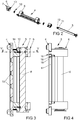
- FIG 2 shows an exploded view of the rotary bearing 3 Figure 1 , To simplify the drawing, the bearing belt 5 is not shown.
- the pivot bearing 3 has two fork legs 6 of the bearing fork part 4 and securing elements 7 inserted into the fork legs 6 to support a bearing bolt 8. This is in the bearing bolt 8 Figure 1 bearing belt 5 shown rotatably.
- the securing elements 7 sit down each composed of a base element 9 and a spring element 10.
- the bearing pin 8 has constrictions 11 for receiving a partial area of the spring elements 10 and at its free end a chamfer 12 for insertion into the securing elements 7.
- the securing elements 7 have shells 13 arranged in the basic elements 9 for the bearing pin.
- Figure 3 shows enlarged a longitudinal section through the rotary bearing 3, in which to simplify the drawing, the bearing band 5 Figure 1 is not shown. It can be seen here that the fork legs 6 overlap the securing elements 7 in a bow-shaped manner.
- the spring element 10 is arranged in a recess 14 in the base element 9 and secures the bearing pin 8 in the axial direction. Furthermore, the bearing fork part has 4 screw recesses 15 for screwing to the in Figure 1 shown frame 1.
- Figure 4 shows the pivot bearing 3 Figure 3 in a side view. It can be seen here that the bow-shaped fork legs 6 penetrate into a recess 16 of a base plate 17 of the bearing fork part 4 and are held there in a form-fitting manner. Furthermore, the bearing fork part 4 each has a recess 18 on the fork legs 6 for receiving a nose 19 of the base element 9 of the securing element 7. The recesses 18 of the two fork legs 6 face each other. The securing elements 7, which are held at a distance from one another by the bearing pin 8, are thus held axially immovably in the bearing fork part 4.
- Figure 5 illustrates the design of the bow-shaped fork leg 6 in a cross section through the bearing fork part 4 Figure 3 along the line V - V.
- the bow-shaped part of the fork leg 6 is angled from the flat base plate 17 of the bearing fork part 4 and inserted with the free end into the recess 16 of the base plate 17.
- the base plate 17 can also have two opposite recesses 16 for the positive reception of both ends of a separate bracket of the fork leg 6.
- the base element 9 and the spring element 10 are preassembled to the securing element 7 and inserted into the fork leg 6 shown.
- the bow-shaped part of the fork leg 6 becomes after the assembly of the securing element 7 the base plate 17 is bent around the preassembled securing element 7 and connected to the base plate 17 of the bearing fork part 4.
- Figure 6 shows the spring element 10 enlarged in a perspective view. It can be seen here that the spring element 10 is bent from a spring wire. According to an embodiment of the invention, but not shown, the holding element 20 of the spring element 10, which is received by the recess 21, can be rotated by 90 ° with respect to the rest of the spring element 10.
- Figure 7 shows a further embodiment of the rotary bearing 3 in a cross section analogous to that of FIG Figure 5 ,
- a fork leg 106 has a recess 121 for receiving a holding element 120 of a spring element 110 of a securing element 107.
- a support edge 122 of the spring element 110 penetrates as in the embodiment Figure 5 into the constriction 11 of the bearing pin 8.
- a base element 109 of the securing element 107 has a recess 114 for receiving the spring element 110.
- Figure 8 shows the spring element 110 Figure 7 in a perspective view.
- the spring element 110 is made of spring plate.
- Spring elements 10, 110 shown have in common that the supporting edge 22, 122 can spring in the direction of the holding element 20, 120.
- This design is advantageous if the fork bearing part 4 with the two securing elements 7, 107 is preassembled and the bearing axis 8 is inserted as the last working step for mounting the pivot bearing 3.
- the support edges 22, 122 are pushed away from the chamfer 12 of the bearing axis 8 and snap into the constrictions 11.
- Figure 9 shows a further embodiment of the rotary bearing 3 in a cross section analogous to that of FIG Figure 5 , This embodiment differs from that Figure 5 above all in that a fork leg 206 has two recesses 221 for receiving holding elements 220 of a spring element 210 of a securing element 207. A base element 209 of the securing element 207 has a recess 214 for receiving the spring element 210.
- Figure 10 shows the spring element 210 of FIG Figure 9 illustrated embodiment.
- the spring element 210 is made of spring sheet metal and has two holding elements 220 designed as holding clamps for holding in the recesses 221 of the fork leg 206 and a web-like support edge 222 with which it fits into the constriction 11 of FIG Figure 9 illustrated bearing pin 8 penetrates.
- the illustrated spring element 210 cannot spring back the support edge 222 when inserted into the fork leg 206, as in the other embodiments.
- the bearing pin 8 with the two securing elements 207 are therefore preassembled and placed on the fork bearing part 4.
- the fork legs 206 are then bent around the securing elements 207.
Landscapes
- Engineering & Computer Science (AREA)
- Mechanical Engineering (AREA)
- Pivots And Pivotal Connections (AREA)
- Hinges (AREA)
Abstract
Description
- Die Erfindung betrifft ein Drehlager für einen gegen einen Rahmen schwenkbaren Flügel eines Fensters, einer Fenstertür oder dergleichen, mit einem Gabelschenkel aufweisenden Lagergabelteil, mit einem Lagerbolzen, und mit einem Sicherungselement zur axialen Sicherung des Lagerbolzens an einem der Gabelschenkel. Weiterhin betrifft die Erfindung ein Verfahren zur Montage eines solchen Drehlagers für einen gegen einen Rahmen schwenkbaren Flügel.
- Solche Drehlager werden insbesondere bei Drehbeschlägen oder Dreh-Kipp-Beschlägen eingesetzt und erfordern eine zuverlässige Sicherung des Lagerbolzens gegen ein Herausfallen.
- Die
EP 2 636 831 A1 offenbart ein Lager für Flügel von Fenstern mit einem einstückigen Lagergabelteil, in das ein Federelement eingesetzt ist. Das Federelement umgreift eine keilförmige Kontur im Inneren des Lagergabelteils und ragt mit einem Bügel in eine Ausnehmung des Lagerbolzens hinein. Hierdurch ist das Lager jedoch sehr unflexibel. Ein Lagerbolzen mit einem größeren Durchmesser würde ein völlig neues Lagergabelteil erfordern. - Aus der
EP 1 180 570 B1 ist ein Lager bekannt geworden, bei dem von einer Befestigungsplatte zwei Schenkel zur Lagerung einer Scharnierspindel abgewinkelt sind. Eine Lageröse sichert die Scharnierspindel an einem der Schenkel. Auch diese Lagerung lässt sich nur mit großem Aufwand an unterschiedliche Aufgaben anpassen. - Der Erfindung liegt das Problem zugrunde, ein Drehlager der eingangs genannten Art so zu gestalten, dass es eine hohe Stabilität hat und einfach auf verschiedene Aufgaben angepasst werden kann. Weiterhin soll ein Verfahren zur Montage eines solchen Drehlagers geschaffen werden.
- Das erstgenannte Problem wird erfindungsgemäß dadurch gelöst, dass das Sicherungselement ein in einem der Gabelschenkel angeordnetes Grundelement und ein Federelement hat und dass das Grundelement und das Federelement als separate Bauteile ausgebildet sind.
- Durch diese Gestaltung lassen sich die Bauteile des Sicherungselementes einfach auf die jeweiligen Aufgaben des Drehlagers anpassen. So kann für besonders schwere Flügel das Grundelement aus einem hochfesten Material gefertigt sein. Mithin kann das Grundelement vorzugsweise aus Kunststoff beispielsweise im Spritzgussverfahren gefertigt werden, wodurch sich das Drehlager kostengünstig gestalten lässt. Ebenfalls lassen sich je nach Aufgabe unterschiedlich gestaltete Federelemente einsetzen und hierdurch das Drehlager einfach anpassen. Zudem lässt sich eine vorgesehene Stabilität des Drehlagers durch eine geeignete Wahl der Bauteile des Sicherungselementes einfach sicherstellen.
- Die Lagerung weist gemäß einer vorteilhaften Weiterbildung der Erfindung eine hohe Stabilität auf, wenn der Gabelschenkel bügelförmig, das Grundelement übergreifend gestaltet ist. Damit ist das Grundelement in den Gabelschenkel eingesetzt und wird von dem Lagerbolzen aus gesehen in radialer Richtung abgestützt. Da der Lagerbolzen in axialer Richtung von dem Federelement gehalten ist, werden Kräfte zuverlässig abgestützt. Dies trägt zur Erhöhung der Stabilität des Drehlagers bei.
- Die Lagerung des Flügels an dem Lagerbolzen gestaltet sich gemäß einer anderen vorteilhaften Weiterbildung der Erfindung konstruktiv besonders einfach, wenn das Grundelement drehfest an zumindest einem der Bauteile des Gabelschenkels oder des Lagerbolzens gehalten ist. Der Gabelschenkel kann hierzu unrund gestaltet sein. Der Lagerbolzen kann hierzu eine Abflachung aufweisen. Das Grundelement hat dabei eine dem Gabelschenkel oder dem Lagerbolzen angepasste Kontur.
- Das Drehlager lässt sich gemäß einer anderen vorteilhaften Weiterbildung der Erfindung einfach auf die vorgesehenen Aufgaben anpassen, wenn das Grundelement eine Schale für den Lagerbolzen aufweist.
- Die Montage der Bauteile des Drehlagers gestaltet sich gemäß einer anderen vorteilhaften Weiterbildung der Erfindung besonders einfach, wenn das Federelement den Gabelschenkel mit dem Grundelement und dem Lagerbolzen verbindet.
- Die Lagerung weist gemäß einer anderen vorteilhaften Weiterbildung der Erfindung eine besonders hohe Stabilität auf, wenn das Grundelement eine Ausnehmung zur Aufnahme des Federelementes hat. Hierdurch gestaltet sich das Drehlager zudem besonders einfach, wenn das Federelement in einer Richtung aus der Ausnehmung herausragt, um einen Formschluss mit dem Gabelschenkel zu erzeugen, und in einer anderen Richtung aus der Ausnehmung herausragt, um einen Formschluss mit dem Lagerbolzen zu erzeugen.
- Die formschlüssige Verbindung des Sicherungselementes mit dem Gabelschenkel gestaltet sich gemäß einer anderen vorteilhaften Weiterbildung der Erfindung konstruktiv besonders einfach, wenn der Gabelschenkel eine Ausnehmung zur Aufnahme eines Teilbereichs des Federelementes hat. Damit ermöglicht das Federelement die direkte Übertragung von Kräften von dem Lagerbolzen auf das Lagergabelteil.
- Das Drehlager lässt sich gemäß einer anderen vorteilhaften Weiterbildung der Erfindung besonders kostengünstig fertigen, wenn das Federelement aus Federdraht oder Federblech gefertigt ist.
- Gemäß einer anderen vorteilhaften Weiterbildung der Erfindung erfüllt das Federelement seine Funktion besonders zuverlässig, wenn der Teilbereich des Federelementes, welcher in der Ausnehmung aufgenommen wird, gegenüber dem restlichen Federelement um 90°.
- Das zweit genannte Problem, nämlich die Schaffung eines Verfahrens zur Montage des Drehlagers wird erfindungsgemäß dadurch gelöst, dass das Grundelement mit dem Federelement zu dem Sicherungselement vormontiert wird und dass das Sicherungselement in den Gabelschenkel eingesetzt wird oder dass der Gabelschenkel nach der Vormontage des aus Grundelement und Federelement vormontierten Sicherungselement mit dem übrigen Bereich des Lagergabelteil verbunden wird.
- Damit lässt sich das Drehlager einfach montieren. Das Drehlager hat daher eine hohe Stabilität.
- Die Erfindung lässt zahlreiche Ausführungsformen zu. Zur weiteren Verdeutlichung ihres Grundprinzips sind mehrere davon in der Zeichnung dargestellt und werden nachfolgend beschrieben. Diese zeigt in
- Fig.1
- einen Teilbereich eines Fensters mit einem Drehlager,
- Fig.2
- eine Explosionsdarstellung des Drehlagers aus
Figur 1 , - Fig.3
- vergrößert eine Schnittdarstellung des Drehlagers aus
Figur 1 , - Fig.4
- eine Seitenansicht des Drehlagers aus
Figur 1 , - Fig.5
- einen Querschnitt durch das Drehlager aus
Figur 3 entlang der Linie III - III, - Fig.6
- perspektivisch ein Federelement des Drehlagers aus
Figur 5 in einer vergrößerten Darstellung, - Fig.7
- einen Querschnitt durch eine weitere Ausführungsform des Drehlagers,
- Fig.8
- perspektivisch ein Federelement des Drehlagers aus
Figur 7 in einer vergrößerten Darstellung, - Fig.9
- einen Querschnitt durch eine weitere Ausführungsform des Drehlagers aus
Figur 8 , - Fig.10
- perspektivisch ein Federelement des Drehlagers aus
Figur 9 in einer vergrößerten Darstellung. -
Figur 1 zeigt einen Teilbereich eines Fensters mit einem gegen einen Rahmen 1 schwenkbaren Flügel 2 und einem Drehlager 3. Das Drehlager 3 hat ein an dem Rahmen 1 befestigtes Lagergabelteil 4 und ein an dem Flügel 2 angelenktes Lagerband 5. Das Lagerband 5 kann beispielsweise ein Bauteil eines Scherenlagers eines Dreh-Kipp-Beschlags sein oder Teil einer reinen Drehlagerung sein. -
Figur 2 zeigt eine Explosionsdarstellung des Drehlagers 3 ausFigur 1 . Zur Vereinfachung der Zeichnung ist das Lagerband 5 nicht dargestellt. Das Drehlager 3 hat zwei Gabelschenkel 6 des Lagergabelteils 4 und in die Gabelschenkel 6 eingesetzte Sicherungselemente 7 zur Abstützung eines Lagerbolzens 8. Auf dem Lagerbolzen 8 ist das inFigur 1 dargestellte Lagerband 5 drehbar gelagert. Die Sicherungselemente 7 setzen sich jeweils aus einem Grundelement 9 und einem Federelement 10 zusammen. Der Lagerbolzen 8 hat Einschnürungen 11 zur Aufnahme eines Teilbereichs der Federelemente 10 und an seinem freien Ende eine Fase 12, zum Einführen in die Sicherungselemente 7. Die Sicherungselemente 7 haben in den Grundelementen 9 angeordnete Schalen 13 für den Lagerbolzen. -
Figur 3 zeigt vergrößert einen Längsschnitt durch das Drehlager 3, bei dem zur Vereinfachung der Zeichnung das Lagerband 5 ausFigur 1 nicht dargestellt ist. Hierbei ist zu erkennen, dass die Gabelschenkel 6 die Sicherungselemente 7 bügelförmig übergreifen. Das Federelement 10 ist in einer Ausnehmung 14 im Grundelement 9 angeordnet und sichert den Lagerbolzen 8 in axialer Richtung. Weiterhin hat das Lagergabelteil 4 Schraubausnehmungen 15 zur Verschraubung mit dem inFigur 1 dargestellten Rahmen 1. -
Figur 4 zeigt das Drehlager 3 ausFigur 3 in einer Seitenansicht. Hierbei ist zu erkennen, dass die bügelförmig gestalteten Gabelschenkel 6 in eine Ausnehmung 16 einer Grundplatte 17 des Lagergabelteils 4 eindringen und dort formschlüssig gehalten sind. Weiterhin hat das Lagergabelteil 4 an den Gabelschenkeln 6 jeweils eine Ausnehmung 18 zur Aufnahme einer Nase 19 des Grundelements 9 des Sicherungselements 7. Die Ausnehmungen 18 der beiden Gabelschenkel 6 sind einander zugewandt. Damit sind die durch den Lagerbolzen 8 auf Abstand zueinander gehaltene Sicherungselemente 7 axial unverschieblich in dem Lagergabelteil 4 gehalten. -
Figur 5 verdeutlicht die Gestaltung des bügelförmigen Gabelschenkels 6 in einem Querschnitt durch das Lagergabelteil 4 ausFigur 3 entlang der Linie V - V. Der bügelförmige Teil des Gabelschenkels 6 ist von der ebenen Grundplatte 17 des Lagergabelteils 4 abgewinkelt und mit dem freien Ende in die Ausnehmung 16 der Grundplatte 17 eingeführt. In einer alternativen, nicht dargestellten Ausführungsform kann auch die Grundplatte 17 zwei gegenüberliegende Ausnehmungen 16 zur formschlüssigen Aufnahme beider Enden eines separaten Bügels des Gabelschenkels 6 aufweisen. - Bei der Montage des Drehlagers 3 werden das Grundelement 9 und das Federelement 10 zu dem Sicherungselement 7 vormontiert und in den dargestellten Gabelschenkel 6 eingesetzt. In einer alternativen Ausführungsform der Montage des Drehlagers 3 wird der bügelförmige Teil des Gabelschenkels 6 nach der Montage des Sicherungselementes 7 an der Grundplatte 17 um das vormontierte Sicherungselement 7 herum gebogen und mit der Grundplatte 17 des Lagergabelteils 4 verbunden.
- Weiterhin zeigt
Figur 5 , dass das Federelement 10 mit einem bogenförmig gestalteten Haltelement 20 in eine weitere Ausnehmung 21 des Lagergabelteils 4 und mit einer Stützkante 22 in die eine Einschnürung 11 des Lagerbolzens 8 eindringt. Damit erzeugt das Federelement 10 einen Formschluss zwischen Lagergabelteil 4 und Lagerbolzen 8. Der Lagerbolzen 8 hat eine Abflachung 23, mit der er in der Schale 13 des Grundelements 9 drehfest gehalten ist. -
Figur 6 zeigt das Federelement 10 vergrößert in einer perspektivischen Darstellung. Hierbei ist zu erkennen, dass das Federelement 10 aus einem Federdraht gebogen ist. Gemäß einer erfindungsgemäßen, aber nicht dargestellten, Weiterbildung der Erfindung kann das Halteelement 20 des Federelementes 10, welches von der Ausnehmung 21 aufgenommen wird, gegenüber dem restlichen Federelement 10 um 90° gedreht verlaufen. -
Figur 7 zeigt eine weitere Ausführungsform des Drehlagers 3 in einem Querschnitt analog zu dem ausFigur 5 . Ein Gabelschenkel 106 hat eine Ausnehmung 121 zur Aufnahme eines Halteelementes 120 eines Federelementes 110 eines Sicherungselementes 107. Eine Stützkante 122 des Federelementes 110 dringt wie bei der Ausführungsform nachFigur 5 in die Einschnürung 11 des Lagerbolzens 8 ein. Ein Grundelement 109 des Sicherungselementes 107 hat eine Ausnehmung 114 zur Aufnahme des Federelementes 110. -
Figur 8 zeigt das Federelement 110 ausFigur 7 in einer perspektivischen Darstellung. Das Federelement 110 ist aus Federblech gefertigt. - Die in den
Figuren 6 und 8 dargestellten Federelemente 10, 110 haben die Gemeinsamkeit, dass die Stützkante 22, 122 in Richtung des Halteelementes 20, 120 federn kann. Diese Gestaltung ist von Vorteil, wenn man zur Montage des Drehlagers 3 das Gabellagerteil 4 mit den beiden Sicherungselementen 7, 107 vormontiert und die Lagerachse 8 als letzten Arbeitsgang einführt. Dabei werden von der Fase 12 der Lagerachse 8 die Stützkanten 22, 122 weggedrückt und schnappen in den Einschnürungen 11 ein. -
Figur 9 zeigt eine weitere Ausführungsform des Drehlagers 3 in einem Querschnitt analog zu dem ausFigur 5 . Diese Ausführungsform unterscheidet sich von der ausFigur 5 vor allem dadurch, dass ein Gabelschenkel 206 zwei Ausnehmungen 221 zur Aufnahme von Halteelementen 220 eines Federelementes 210 eines Sicherungselementes 207 hat. Ein Grundelement 209 des Sicherungselementes 207 hat eine Ausnehmung 214 zur Aufnahme des Federelementes 210. -
Figur 10 zeigt das Federelement 210 der inFigur 9 dargestellten Ausführungsform. Das Federelement 210 ist aus Federblech gefertigt und hat zwei als Halteklammern ausgebildete Halteelemente 220 zur Halterung in den Ausnehmungen 221 des Gabelschenkels 206 und eine stegartige Stützkante 222 mit welcher es in die Einschnürung 11 des inFigur 9 dargestellten Lagerbolzens 8 eindringt. - Bei dem in
Figur 10 dargestellten Federelement 210 kann die Stützkante 222 im in den Gabelschenkel 206 eingesetzten Zustand nicht zurückfedern, wie bei den anderen Ausführungsformen. Zur Montage des Drehlagers 3 werden daher der Lagerbolzen 8 mit den beiden Sicherungselementen 207 vormontiert und auf das Gabellagerteil 4 gesetzt. Anschließend werden die Gabelschenkel 206 um die Sicherungselemente 207 herum gebogen.
Claims (10)
- Drehlager (3) für einen gegen einen Rahmen (1) schwenkbaren Flügel (2) eines Fensters, einer Fenstertür oder dergleichen, mit einem Gabelschenkel (6, 106, 206) aufweisenden Lagergabelteil (4), mit einem Lagerbolzen (8), und mit einem Sicherungselement (7, 107, 207) zur axialen Sicherung des Lagerbolzens (8) an einem der Gabelschenkel (6, 106, 206), dadurch gekennzeichnet, dass das Sicherungselement (7, 107, 207) ein in einem der Gabelschenkel (6, 106, 206) angeordnetes Grundelement (9, 109, 209) und ein Federelement (10, 110, 210) hat und dass das Grundelement (9, 109, 209) und das Federelement (10, 110, 210) als separate Bauteile ausgebildet sind.
- Drehlager nach Anspruch 1, dadurch gekennzeichnet, dass der Gabelschenkel (6, 106, 206) bügelförmig, das Grundelement (9, 109, 209) übergreifend gestaltet ist.
- Drehlager nach Anspruch 1 oder 2, dadurch gekennzeichnet, dass das Grundelement (9, 109, 209) drehfest an zumindest einem der Bauteile des Gabelschenkels (6, 106, 206) oder des Lagerbolzens (8) gehalten ist.
- Drehlager nach zumindest einem der Ansprüche 1 bis 3, dadurch gekennzeichnet, dass das Grundelement (9, 109, 209) eine Schale (13) für den Lagerbolzen (8) aufweist.
- Drehlager nach zumindest einem der Ansprüche 1 bis 4, dadurch gekennzeichnet, dass das Federelement (10, 110, 210) den Gabelschenkel (6, 106, 206) mit dem Grundelement (9, 109, 209) und dem Lagerbolzen (8) verbindet.
- Drehlager nach zumindest einem der Ansprüche 1 bis 5, dadurch gekennzeichnet, dass das Grundelement (9, 109, 209) eine Ausnehmung (14, 114, 214) zur Aufnahme des Federelementes (10, 110, 210) hat.
- Drehlager nach zumindest einem der Ansprüche 1 bis 6, dadurch gekennzeichnet, dass der Gabelschenkel (6, 106, 206) eine Ausnehmung (21, 121, 221) zur Aufnahme eines Teilbereichs des Federelementes (10, 110, 210) hat.
- Drehlager nach zumindest einem der Ansprüche 1 bis 7, dadurch gekennzeichnet, dass das Federelement (10, 110, 210) aus Federdraht oder Federblech gefertigt ist.
- Drehlager nach Anspruch 8, dadurch gekennzeichnet, dass der Teilbereich des Federelementes (10, 110, 210), welcher in der Ausnehmung (21, 121, 221) aufgenommen wird, gegenüber dem restlichen Federelement um 90°.
- Verfahren zur Montage eines Drehlagers für einen gegen einen Rahmen (1) schwenkbaren Flügel (2) nach einem der vorhergehenden Ansprüche, dadurch gekennzeichnet, dass das Grundelement (9, 109, 209) mit dem Federelement (10, 110, 210) zu dem Sicherungselement (7, 107, 207) vormontiert wird und dass das Sicherungselement (7, 107, 207) in den Gabelschenkel (6, 106, 206) eingesetzt wird oder dass der Gabelschenkel (6, 106, 206) nach der Vormontage des aus Grundelement (9, 109, 209) und Federelementes (10, 110, 210) vormontierten Sicherungselement (7, 107, 207) mit dem übrigen Bereich des Lagergabelteils (4) verbunden wird.
Priority Applications (4)
| Application Number | Priority Date | Filing Date | Title |
|---|---|---|---|
| PL19179039T PL3587717T3 (pl) | 2018-06-21 | 2019-06-07 | Łożysko obrotowe do skrzydła przechylnego w stosunku do ramy |
| SI201930041T SI3587717T1 (sl) | 2018-06-21 | 2019-06-07 | Vrtljiv ležaj za krilo, vrtljivo glede na okvir |
| RS20210428A RS61681B1 (sr) | 2018-06-21 | 2019-06-07 | Okretni ležaj za krilo koje se može okrenuti ka ramu |
| HRP20210595TT HRP20210595T1 (hr) | 2018-06-21 | 2021-04-14 | Okretni ležaj za krilo koje se može okrenuti prema okviru |
Applications Claiming Priority (1)
| Application Number | Priority Date | Filing Date | Title |
|---|---|---|---|
| DE102018210102.7A DE102018210102A1 (de) | 2018-06-21 | 2018-06-21 | Drehlager für einen gegen einen Rahmen schwenkbaren Flügel und Verfahren zur Montage eines Drehlagers |
Publications (2)
| Publication Number | Publication Date |
|---|---|
| EP3587717A1 true EP3587717A1 (de) | 2020-01-01 |
| EP3587717B1 EP3587717B1 (de) | 2021-03-03 |
Family
ID=66793854
Family Applications (1)
| Application Number | Title | Priority Date | Filing Date |
|---|---|---|---|
| EP19179039.3A Active EP3587717B1 (de) | 2018-06-21 | 2019-06-07 | Drehlager für einen gegen einen rahmen schwenkbaren flügel |
Country Status (9)
| Country | Link |
|---|---|
| EP (1) | EP3587717B1 (de) |
| DE (1) | DE102018210102A1 (de) |
| DK (1) | DK3587717T3 (de) |
| ES (1) | ES2864424T3 (de) |
| HR (1) | HRP20210595T1 (de) |
| HU (1) | HUE054277T2 (de) |
| PL (1) | PL3587717T3 (de) |
| RS (1) | RS61681B1 (de) |
| SI (1) | SI3587717T1 (de) |
Citations (5)
| Publication number | Priority date | Publication date | Assignee | Title |
|---|---|---|---|---|
| DE19521539A1 (de) * | 1995-06-13 | 1996-12-19 | Winkhaus Fa August | Drehlager, insbesondere Scherenlager eines Drehbeschlags oder Dreh-Kippbeschlags für Fenster, Türen oder dergleichen |
| EP0928871A1 (de) * | 1998-01-07 | 1999-07-14 | Ferco International Ferrures et Serrures de Bâtiment | Verbesserung der gelenkigen Verbindung eines Flügels an einem Rahmen |
| EP1180570A1 (de) | 2000-08-10 | 2002-02-20 | FERCO INTERNATIONAL Ferrures et Serrures de Bâtiment, Société Anonyme | Gelenkbeschlag für Türen, Fenster oder dergleichen |
| DE202009005886U1 (de) * | 2009-04-22 | 2009-07-02 | Siegenia-Aubi Kg | Scharnierbeschlag für Fenster oder Türen |
| EP2636831A1 (de) | 2012-03-07 | 2013-09-11 | Roto Frank AG | Lager für Flügel von Fenstern, Türen oder dergleichen mit einem Federelement |
-
2018
- 2018-06-21 DE DE102018210102.7A patent/DE102018210102A1/de not_active Withdrawn
-
2019
- 2019-06-07 ES ES19179039T patent/ES2864424T3/es active Active
- 2019-06-07 DK DK19179039.3T patent/DK3587717T3/da active
- 2019-06-07 HU HUE19179039A patent/HUE054277T2/hu unknown
- 2019-06-07 SI SI201930041T patent/SI3587717T1/sl unknown
- 2019-06-07 RS RS20210428A patent/RS61681B1/sr unknown
- 2019-06-07 EP EP19179039.3A patent/EP3587717B1/de active Active
- 2019-06-07 PL PL19179039T patent/PL3587717T3/pl unknown
-
2021
- 2021-04-14 HR HRP20210595TT patent/HRP20210595T1/hr unknown
Patent Citations (5)
| Publication number | Priority date | Publication date | Assignee | Title |
|---|---|---|---|---|
| DE19521539A1 (de) * | 1995-06-13 | 1996-12-19 | Winkhaus Fa August | Drehlager, insbesondere Scherenlager eines Drehbeschlags oder Dreh-Kippbeschlags für Fenster, Türen oder dergleichen |
| EP0928871A1 (de) * | 1998-01-07 | 1999-07-14 | Ferco International Ferrures et Serrures de Bâtiment | Verbesserung der gelenkigen Verbindung eines Flügels an einem Rahmen |
| EP1180570A1 (de) | 2000-08-10 | 2002-02-20 | FERCO INTERNATIONAL Ferrures et Serrures de Bâtiment, Société Anonyme | Gelenkbeschlag für Türen, Fenster oder dergleichen |
| DE202009005886U1 (de) * | 2009-04-22 | 2009-07-02 | Siegenia-Aubi Kg | Scharnierbeschlag für Fenster oder Türen |
| EP2636831A1 (de) | 2012-03-07 | 2013-09-11 | Roto Frank AG | Lager für Flügel von Fenstern, Türen oder dergleichen mit einem Federelement |
Also Published As
| Publication number | Publication date |
|---|---|
| SI3587717T1 (sl) | 2021-04-30 |
| HUE054277T2 (hu) | 2021-08-30 |
| PL3587717T3 (pl) | 2021-07-19 |
| HRP20210595T1 (hr) | 2021-05-14 |
| DK3587717T3 (da) | 2021-04-19 |
| RS61681B1 (sr) | 2021-05-31 |
| ES2864424T3 (es) | 2021-10-13 |
| EP3587717B1 (de) | 2021-03-03 |
| DE102018210102A1 (de) | 2019-12-24 |
Similar Documents
| Publication | Publication Date | Title |
|---|---|---|
| EP1375273B1 (de) | Scheibenwischvorrichtung | |
| DE9306387U1 (de) | Federscharnier für Brille | |
| DE102012009173B4 (de) | Toleranzausgleichseinrichtung | |
| DE4112132B4 (de) | Hebelwerk | |
| DE102017109996A1 (de) | Radlenker mit einem ersten und zweiten Profilkörper | |
| EP2546438B1 (de) | Zur verschieblichen Montage in einer einen Hinterschnitt aufweisenden Beschlagnut vorgesehenes Beschlagteil | |
| WO2003004901A1 (de) | Gummilager, vorzugsweise stabilisatorlager, und verfahren zur montage des lagers | |
| DE10312136B4 (de) | Anordnung zur Feststellung und Neigungsverstellung an einem Fahrzeugsitz sowie Montageverfahren für diese Anordnung | |
| DE102012208024B4 (de) | Scharnierlager, insbesondere für eine Tür oder Klappe eines Kraftfahrzeugs | |
| EP2913465B1 (de) | Bandanordnung für türen, fenster oder dergleichen | |
| EP3587717A1 (de) | Drehlager für einen gegen einen rahmen schwenkbaren flügel und verfahren zur montage eines drehlagers | |
| EP2141310B1 (de) | Montageverbindung mit Federelement für Handhabe | |
| EP0672463B1 (de) | Farbroller | |
| EP1936083B1 (de) | Stützvorrichtung für ein Scharnier einer Schließeinheit | |
| WO1999042346A1 (de) | Viergelenkwischarm für eine scheibenwischanlage | |
| EP3574813B1 (de) | Scharnier für eine toilettensitzgarnitur | |
| DE202009008840U1 (de) | Türflügel | |
| DE102006001509B3 (de) | Scharnier für Türen oder Fenster sowie Verfahren zum Einsetzen eines für die Verstellung notwendigen Scharnierzapfens in einen Scharnierkopf bei einem Scharnier | |
| EP2305932B1 (de) | Bandteil mit verdeckter Verschraubung | |
| EP2893110B1 (de) | Anschlaganordnung für ein lageveränderbares element an einer fahrzeugkarosserie | |
| EP3543444B1 (de) | Lager für eine beschlaganordnung eines fensters | |
| DE202007016708U1 (de) | Band für Türen, Fenster o.dgl. | |
| EP3683387B1 (de) | Halteelement eines beschlagteils eines treibstangenbeschlages | |
| EP2636831A1 (de) | Lager für Flügel von Fenstern, Türen oder dergleichen mit einem Federelement | |
| EP4343095A1 (de) | Ecklager für einen dreh-kipp beschlag |
Legal Events
| Date | Code | Title | Description |
|---|---|---|---|
| PUAI | Public reference made under article 153(3) epc to a published international application that has entered the european phase |
Free format text: ORIGINAL CODE: 0009012 |
|
| STAA | Information on the status of an ep patent application or granted ep patent |
Free format text: STATUS: THE APPLICATION HAS BEEN PUBLISHED |
|
| AK | Designated contracting states |
Kind code of ref document: A1 Designated state(s): AL AT BE BG CH CY CZ DE DK EE ES FI FR GB GR HR HU IE IS IT LI LT LU LV MC MK MT NL NO PL PT RO RS SE SI SK SM TR |
|
| AX | Request for extension of the european patent |
Extension state: BA ME |
|
| STAA | Information on the status of an ep patent application or granted ep patent |
Free format text: STATUS: REQUEST FOR EXAMINATION WAS MADE |
|
| 17P | Request for examination filed |
Effective date: 20200605 |
|
| RBV | Designated contracting states (corrected) |
Designated state(s): AL AT BE BG CH CY CZ DE DK EE ES FI FR GB GR HR HU IE IS IT LI LT LU LV MC MK MT NL NO PL PT RO RS SE SI SK SM TR |
|
| GRAP | Despatch of communication of intention to grant a patent |
Free format text: ORIGINAL CODE: EPIDOSNIGR1 |
|
| STAA | Information on the status of an ep patent application or granted ep patent |
Free format text: STATUS: GRANT OF PATENT IS INTENDED |
|
| INTG | Intention to grant announced |
Effective date: 20201020 |
|
| GRAS | Grant fee paid |
Free format text: ORIGINAL CODE: EPIDOSNIGR3 |
|
| GRAA | (expected) grant |
Free format text: ORIGINAL CODE: 0009210 |
|
| STAA | Information on the status of an ep patent application or granted ep patent |
Free format text: STATUS: THE PATENT HAS BEEN GRANTED |
|
| AK | Designated contracting states |
Kind code of ref document: B1 Designated state(s): AL AT BE BG CH CY CZ DE DK EE ES FI FR GB GR HR HU IE IS IT LI LT LU LV MC MK MT NL NO PL PT RO RS SE SI SK SM TR |
|
| REG | Reference to a national code |
Ref country code: GB Ref legal event code: FG4D Free format text: NOT ENGLISH |
|
| REG | Reference to a national code |
Ref country code: CH Ref legal event code: EP Ref country code: AT Ref legal event code: REF Ref document number: 1367365 Country of ref document: AT Kind code of ref document: T Effective date: 20210315 |
|
| REG | Reference to a national code |
Ref country code: DE Ref legal event code: R096 Ref document number: 502019000896 Country of ref document: DE |
|
| REG | Reference to a national code |
Ref country code: IE Ref legal event code: FG4D Free format text: LANGUAGE OF EP DOCUMENT: GERMAN |
|
| REG | Reference to a national code |
Ref country code: RO Ref legal event code: EPE |
|
| REG | Reference to a national code |
Ref country code: HR Ref legal event code: TUEP Ref document number: P20210595T Country of ref document: HR |
|
| REG | Reference to a national code |
Ref country code: DK Ref legal event code: T3 Effective date: 20210412 |
|
| REG | Reference to a national code |
Ref country code: NL Ref legal event code: FP |
|
| REG | Reference to a national code |
Ref country code: HR Ref legal event code: T1PR Ref document number: P20210595 Country of ref document: HR |
|
| REG | Reference to a national code |
Ref country code: GR Ref legal event code: EP Ref document number: 20210400790 Country of ref document: GR Effective date: 20210519 |
|
| REG | Reference to a national code |
Ref country code: SK Ref legal event code: T3 Ref document number: E 37009 Country of ref document: SK |
|
| REG | Reference to a national code |
Ref country code: HR Ref legal event code: ODRP Ref document number: P20210595 Country of ref document: HR Payment date: 20210518 Year of fee payment: 3 |
|
| REG | Reference to a national code |
Ref country code: LT Ref legal event code: MG9D |
|
| PG25 | Lapsed in a contracting state [announced via postgrant information from national office to epo] |
Ref country code: NO Free format text: LAPSE BECAUSE OF FAILURE TO SUBMIT A TRANSLATION OF THE DESCRIPTION OR TO PAY THE FEE WITHIN THE PRESCRIBED TIME-LIMIT Effective date: 20210603 Ref country code: LT Free format text: LAPSE BECAUSE OF FAILURE TO SUBMIT A TRANSLATION OF THE DESCRIPTION OR TO PAY THE FEE WITHIN THE PRESCRIBED TIME-LIMIT Effective date: 20210303 Ref country code: FI Free format text: LAPSE BECAUSE OF FAILURE TO SUBMIT A TRANSLATION OF THE DESCRIPTION OR TO PAY THE FEE WITHIN THE PRESCRIBED TIME-LIMIT Effective date: 20210303 |
|
| REG | Reference to a national code |
Ref country code: HU Ref legal event code: AG4A Ref document number: E054277 Country of ref document: HU |
|
| PG25 | Lapsed in a contracting state [announced via postgrant information from national office to epo] |
Ref country code: LV Free format text: LAPSE BECAUSE OF FAILURE TO SUBMIT A TRANSLATION OF THE DESCRIPTION OR TO PAY THE FEE WITHIN THE PRESCRIBED TIME-LIMIT Effective date: 20210303 Ref country code: SE Free format text: LAPSE BECAUSE OF FAILURE TO SUBMIT A TRANSLATION OF THE DESCRIPTION OR TO PAY THE FEE WITHIN THE PRESCRIBED TIME-LIMIT Effective date: 20210303 |
|
| REG | Reference to a national code |
Ref country code: ES Ref legal event code: FG2A Ref document number: 2864424 Country of ref document: ES Kind code of ref document: T3 Effective date: 20211013 |
|
| PG25 | Lapsed in a contracting state [announced via postgrant information from national office to epo] |
Ref country code: SM Free format text: LAPSE BECAUSE OF FAILURE TO SUBMIT A TRANSLATION OF THE DESCRIPTION OR TO PAY THE FEE WITHIN THE PRESCRIBED TIME-LIMIT Effective date: 20210303 Ref country code: EE Free format text: LAPSE BECAUSE OF FAILURE TO SUBMIT A TRANSLATION OF THE DESCRIPTION OR TO PAY THE FEE WITHIN THE PRESCRIBED TIME-LIMIT Effective date: 20210303 |
|
| PG25 | Lapsed in a contracting state [announced via postgrant information from national office to epo] |
Ref country code: PT Free format text: LAPSE BECAUSE OF FAILURE TO SUBMIT A TRANSLATION OF THE DESCRIPTION OR TO PAY THE FEE WITHIN THE PRESCRIBED TIME-LIMIT Effective date: 20210705 Ref country code: IS Free format text: LAPSE BECAUSE OF FAILURE TO SUBMIT A TRANSLATION OF THE DESCRIPTION OR TO PAY THE FEE WITHIN THE PRESCRIBED TIME-LIMIT Effective date: 20210703 |
|
| REG | Reference to a national code |
Ref country code: DE Ref legal event code: R097 Ref document number: 502019000896 Country of ref document: DE |
|
| PLBE | No opposition filed within time limit |
Free format text: ORIGINAL CODE: 0009261 |
|
| STAA | Information on the status of an ep patent application or granted ep patent |
Free format text: STATUS: NO OPPOSITION FILED WITHIN TIME LIMIT |
|
| PG25 | Lapsed in a contracting state [announced via postgrant information from national office to epo] |
Ref country code: AL Free format text: LAPSE BECAUSE OF FAILURE TO SUBMIT A TRANSLATION OF THE DESCRIPTION OR TO PAY THE FEE WITHIN THE PRESCRIBED TIME-LIMIT Effective date: 20210303 Ref country code: MC Free format text: LAPSE BECAUSE OF FAILURE TO SUBMIT A TRANSLATION OF THE DESCRIPTION OR TO PAY THE FEE WITHIN THE PRESCRIBED TIME-LIMIT Effective date: 20210303 |
|
| 26N | No opposition filed |
Effective date: 20211206 |
|
| PG25 | Lapsed in a contracting state [announced via postgrant information from national office to epo] |
Ref country code: LU Free format text: LAPSE BECAUSE OF NON-PAYMENT OF DUE FEES Effective date: 20210607 |
|
| PG25 | Lapsed in a contracting state [announced via postgrant information from national office to epo] |
Ref country code: IE Free format text: LAPSE BECAUSE OF NON-PAYMENT OF DUE FEES Effective date: 20210607 |
|
| PG25 | Lapsed in a contracting state [announced via postgrant information from national office to epo] |
Ref country code: IS Free format text: LAPSE BECAUSE OF FAILURE TO SUBMIT A TRANSLATION OF THE DESCRIPTION OR TO PAY THE FEE WITHIN THE PRESCRIBED TIME-LIMIT Effective date: 20210703 |
|
| REG | Reference to a national code |
Ref country code: HR Ref legal event code: ODRP Ref document number: P20210595 Country of ref document: HR Payment date: 20220527 Year of fee payment: 4 |
|
| REG | Reference to a national code |
Ref country code: CH Ref legal event code: PL |
|
| PG25 | Lapsed in a contracting state [announced via postgrant information from national office to epo] |
Ref country code: LI Free format text: LAPSE BECAUSE OF NON-PAYMENT OF DUE FEES Effective date: 20220630 Ref country code: CH Free format text: LAPSE BECAUSE OF NON-PAYMENT OF DUE FEES Effective date: 20220630 |
|
| REG | Reference to a national code |
Ref country code: HR Ref legal event code: ODRP Ref document number: P20210595 Country of ref document: HR Payment date: 20230601 Year of fee payment: 5 |
|
| P01 | Opt-out of the competence of the unified patent court (upc) registered |
Effective date: 20230516 |
|
| PG25 | Lapsed in a contracting state [announced via postgrant information from national office to epo] |
Ref country code: CY Free format text: LAPSE BECAUSE OF FAILURE TO SUBMIT A TRANSLATION OF THE DESCRIPTION OR TO PAY THE FEE WITHIN THE PRESCRIBED TIME-LIMIT Effective date: 20210303 |
|
| PG25 | Lapsed in a contracting state [announced via postgrant information from national office to epo] |
Ref country code: MK Free format text: LAPSE BECAUSE OF FAILURE TO SUBMIT A TRANSLATION OF THE DESCRIPTION OR TO PAY THE FEE WITHIN THE PRESCRIBED TIME-LIMIT Effective date: 20210303 |
|
| REG | Reference to a national code |
Ref country code: HR Ref legal event code: ODRP Ref document number: P20210595 Country of ref document: HR Payment date: 20240529 Year of fee payment: 6 |
|
| PG25 | Lapsed in a contracting state [announced via postgrant information from national office to epo] |
Ref country code: MT Free format text: LAPSE BECAUSE OF FAILURE TO SUBMIT A TRANSLATION OF THE DESCRIPTION OR TO PAY THE FEE WITHIN THE PRESCRIBED TIME-LIMIT Effective date: 20210303 |
|
| REG | Reference to a national code |
Ref country code: DE Ref legal event code: R081 Ref document number: 502019000896 Country of ref document: DE Owner name: AUG. WINKHAUS SE & CO. KG, DE Free format text: FORMER OWNER: AUG. WINKHAUS GMBH & CO. KG, 48291 TELGTE, DE Ref country code: DE Ref legal event code: R081 Ref document number: 502019000896 Country of ref document: DE Owner name: AUG. WINKHAUS SE, DE Free format text: FORMER OWNER: AUG. WINKHAUS GMBH & CO. KG, 48291 TELGTE, DE |
|
| REG | Reference to a national code |
Ref country code: HR Ref legal event code: ODRP Ref document number: P20210595 Country of ref document: HR Payment date: 20250527 Year of fee payment: 7 |
|
| PGFP | Annual fee paid to national office [announced via postgrant information from national office to epo] |
Ref country code: PL Payment date: 20250529 Year of fee payment: 7 Ref country code: DE Payment date: 20250618 Year of fee payment: 7 |
|
| PGFP | Annual fee paid to national office [announced via postgrant information from national office to epo] |
Ref country code: GB Payment date: 20250620 Year of fee payment: 7 Ref country code: DK Payment date: 20250618 Year of fee payment: 7 |
|
| PGFP | Annual fee paid to national office [announced via postgrant information from national office to epo] |
Ref country code: RS Payment date: 20250528 Year of fee payment: 7 |
|
| PGFP | Annual fee paid to national office [announced via postgrant information from national office to epo] |
Ref country code: NL Payment date: 20250618 Year of fee payment: 7 Ref country code: BE Payment date: 20250617 Year of fee payment: 7 |
|
| PGFP | Annual fee paid to national office [announced via postgrant information from national office to epo] |
Ref country code: HR Payment date: 20250527 Year of fee payment: 7 |
|
| PGFP | Annual fee paid to national office [announced via postgrant information from national office to epo] |
Ref country code: FR Payment date: 20250618 Year of fee payment: 7 Ref country code: HU Payment date: 20250602 Year of fee payment: 7 |
|
| PGFP | Annual fee paid to national office [announced via postgrant information from national office to epo] |
Ref country code: GR Payment date: 20250616 Year of fee payment: 7 Ref country code: BG Payment date: 20250613 Year of fee payment: 7 |
|
| PGFP | Annual fee paid to national office [announced via postgrant information from national office to epo] |
Ref country code: RO Payment date: 20250603 Year of fee payment: 7 Ref country code: AT Payment date: 20250616 Year of fee payment: 7 |
|
| PGFP | Annual fee paid to national office [announced via postgrant information from national office to epo] |
Ref country code: TR Payment date: 20250530 Year of fee payment: 7 Ref country code: SK Payment date: 20250602 Year of fee payment: 7 |
|
| PGFP | Annual fee paid to national office [announced via postgrant information from national office to epo] |
Ref country code: CZ Payment date: 20250523 Year of fee payment: 7 |
|
| PGFP | Annual fee paid to national office [announced via postgrant information from national office to epo] |
Ref country code: SI Payment date: 20250528 Year of fee payment: 7 |
|
| REG | Reference to a national code |
Ref country code: DE Ref legal event code: R081 Ref document number: 502019000896 Country of ref document: DE Owner name: AUG. WINKHAUS SE, DE Free format text: FORMER OWNER: AUG. WINKHAUS SE & CO. KG, 48291 TELGTE, DE |
|
| PGFP | Annual fee paid to national office [announced via postgrant information from national office to epo] |
Ref country code: ES Payment date: 20250718 Year of fee payment: 7 |
|
| PGFP | Annual fee paid to national office [announced via postgrant information from national office to epo] |
Ref country code: IT Payment date: 20250630 Year of fee payment: 7 |